EP2017070B1 - Maschine zur Kompaktierung von zusammenklappbaren Behältern, insbesondere Flaschen aus Kunststoffmaterial und dergleichen - Google Patents
Maschine zur Kompaktierung von zusammenklappbaren Behältern, insbesondere Flaschen aus Kunststoffmaterial und dergleichen Download PDFInfo
- Publication number
- EP2017070B1 EP2017070B1 EP20080160350 EP08160350A EP2017070B1 EP 2017070 B1 EP2017070 B1 EP 2017070B1 EP 20080160350 EP20080160350 EP 20080160350 EP 08160350 A EP08160350 A EP 08160350A EP 2017070 B1 EP2017070 B1 EP 2017070B1
- Authority
- EP
- European Patent Office
- Prior art keywords
- rollers
- container
- machine according
- machine
- compacting
- Prior art date
- Legal status (The legal status is an assumption and is not a legal conclusion. Google has not performed a legal analysis and makes no representation as to the accuracy of the status listed.)
- Not-in-force
Links
- 239000000463 material Substances 0.000 title claims description 6
- 229920003023 plastic Polymers 0.000 title claims description 6
- 239000004033 plastic Substances 0.000 title claims description 6
- 238000005303 weighing Methods 0.000 claims description 5
- 230000003247 decreasing effect Effects 0.000 claims description 3
- 230000005484 gravity Effects 0.000 claims description 3
- 238000012423 maintenance Methods 0.000 claims description 3
- 230000000750 progressive effect Effects 0.000 claims description 3
- 230000005540 biological transmission Effects 0.000 claims description 2
- 239000004698 Polyethylene Substances 0.000 description 1
- 230000004913 activation Effects 0.000 description 1
- 239000004411 aluminium Substances 0.000 description 1
- 229910052782 aluminium Inorganic materials 0.000 description 1
- XAGFODPZIPBFFR-UHFFFAOYSA-N aluminium Chemical compound [Al] XAGFODPZIPBFFR-UHFFFAOYSA-N 0.000 description 1
- 230000000712 assembly Effects 0.000 description 1
- 238000000429 assembly Methods 0.000 description 1
- 235000013361 beverage Nutrition 0.000 description 1
- 238000010276 construction Methods 0.000 description 1
- 238000000605 extraction Methods 0.000 description 1
- 229910052751 metal Inorganic materials 0.000 description 1
- 239000002184 metal Substances 0.000 description 1
- -1 polyethylene Polymers 0.000 description 1
- 229920000573 polyethylene Polymers 0.000 description 1
- 239000013641 positive control Substances 0.000 description 1
- 230000001737 promoting effect Effects 0.000 description 1
- 238000004064 recycling Methods 0.000 description 1
Images



Classifications
-
- B—PERFORMING OPERATIONS; TRANSPORTING
- B30—PRESSES
- B30B—PRESSES IN GENERAL
- B30B9/00—Presses specially adapted for particular purposes
- B30B9/32—Presses specially adapted for particular purposes for consolidating scrap metal or for compacting used cars
- B30B9/321—Presses specially adapted for particular purposes for consolidating scrap metal or for compacting used cars for consolidating empty containers, e.g. cans
- B30B9/325—Presses specially adapted for particular purposes for consolidating scrap metal or for compacting used cars for consolidating empty containers, e.g. cans between rotary pressing members, e.g. rollers, discs
Definitions
- the present invention relates in general to collection and compacting of empty collapsable containers, particularly bottles made of plastic material (polyethylene), aluminium tins, flasks and the like, in order to reduce their volume with a view to disposal and possible recycling thereof.
- the invention relates to a machine for compacting containers of the sort described above using compacting means acting during translation of the container along a path of advance between an inlet and an outlet of the machine.
- a machine of the above type is known for example from the U.S. patent No. US-A-5,522,311 , in which the compacting means are constituted by a pair of flexible endless belts convergent with respect to one another and provided with projections for gripping and perforating the containers each time introduced between them so as to grip and press them progressively.
- said belts are suitable for squeezing the container effectively, they are not able to guarantee a permanent deformation of the collapsed container, i.e., a deformation without a partial elastic return towards the undeformed condition, in the case where the container is made of a plastic material such as, for example, in the case of bottles for beverages.
- the compacting means include a plurality of opposed counter-rotating rollers arranged in succession in contact with the container in said path of advance and comprising a set of rollers situated near to the inlet and defining a section of progressive squeezing of the container from an undeformed condition to a collapsed condition.
- This set of rollers consists of a cylinder of larger diameter and a series of rollers of smaller diameter facing the periphery of the cylinder at progressively decreasing distances from the latter
- the object of the present invention is to overcome the aforesaid drawback, and to provide a machine for compacting collapsible containers suitable for guaranteeing a complete permanent squeezing not only in the case of tins and similar metal containers, but also and in particular in the case of bottles, flasks, and the like, made of plastic material.
- the above object is achieved thanks to the fact that the plurality of rollers further includes a second set of rollers set between the first set of rollers and the outlet and including a plurality of pairs of contiguous rollers of equal diameter arranged at the same distance from each other and defining a section of maintenance of the collapsed condition of the container.
- the inlet of the machine includes a mouth for introduction of the container associated to which are detector means for its identification and first means for temporary arrest of the container in a position corresponding to the detector means.
- second means for temporary arrest of the container in an area corresponding to a selection unit which advantageously includes at least one mobile hatch for discharge of the container outside the machine, which is controlled by the aforesaid detector means.
- said mobile hatch is also advantageously controlled by a device for weighing the container.
- the machine for compacting collapsible containers includes a cabinet 1, contained within which are the functional components described in what follows and which has on its front side an inlet mouth 2, typically of a circular shape, for the introduction of the container that each time is to be compacted.
- the inlet mouth 2 which, for example, has a length of 380 mm and a diameter of 120 mm, is set at a height from the ground of approximately 1.40 m and is inclined downwards by approximately 45°.
- a "chip card” reader 3 for activation of the machine is set adjacent to the inlet mouth 2, and above it a display 4 of a conventional type may be provided, for example, pre-arranged for indicating the instructions for introduction of the containers to be compacted, or else advertising or promotional messages.
- the dorsal side of the cabinet 1 On the side opposite to the inlet mouth 2, the dorsal side of the cabinet 1 has an opening 5 for outlet of the containers each time compacted.
- the outlet opening 5 which is located in the vicinity of the top of the cabinet 1 and from which the containers that have each time been collapsed in a flattened configuration come out, can be connected to a device for supply of a hydraulic press, designed to reduce into compact blocks groups of containers which have been collapsed in succession.
- compacting of the containers is provided by the machine during their translation along a continuous path of advance between the inlet 2 and the outlet 5, via a plurality of counter-rotating and opposed motor-driven rollers, against which the container each time introduced into the machine sets itself in contact along its path of advance.
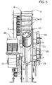
- the machine includes a first set of rollers 7 situated in the proximity of the inlet mouth 2 and in a position underlying it, which defines a section for progressive squeezing of each container from an undeformed condition to a collapsed condition, and a second set of rollers 8 set between the first set of rollers 7 and the outlet 5 and defining a section for maintenance of the collapsed condition of the container.
- the two sets of rollers 7 and 8 are supported in rotation around respective horizontal axes by two sturdy side plates 6 adjacent to the sides of the machine 1 and are driven in rotation via a single electric motor 29 (for example, with a power of 1.5 kW with 4 poles) and respective transmissions, in part with gears and in part with chains.
- a single electric motor 29 for example, with a power of 1.5 kW with 4 poles
- respective transmissions in part with gears and in part with chains.
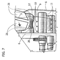
- the first set of rollers 7 includes a cylinder of large diameter 9, from the periphery of which there project series of radial tips 10 ( Figure 7 ), and a series of rollers of smaller diameter facing the periphery of the cylinder 9, in a bottom area of the latter and at distances progressively decreasing in the direction of the second set of rollers 8. Only some of the rollers of the first set 7 are represented in the drawings and designated by 11 in Figures 4 and 7 : in Figure 3 , for simplicity of illustration, only the traces of the corresponding axes thereof are illustrated, which are also designated by the reference 11.
- rollers 11 The arrangement of the above rollers 11 is hence such that the space between said rollers and the cylinder 9 reduces progressively along the path of advance towards the second set of rollers 8 of the container each time introduced into the machine.
- the first set of rollers 7 moreover includes an eccentric roller 12, visible in Figures 4 and 7 , set above the first roller 11 in a position adjacent to the cylinder 9 and having the function of conveying the container each time arriving from the inlet mouth 2 between the cylinder 9 and the rollers 11. Also the eccentric roller 12 is driven in rotation by the same electric motor 29.
- the cylinder 9 is driven in rotation in a counterclockwise direction, whilst the rollers 11 and the eccentric roller 12 rotate in a clockwise direction.
- the rollers 11 can be smooth or else more conveniently be provided at least in part with radial projections shaped like tips, similar to the tips 10 of the cylinder 9, or else with radially projecting axial ribs.
- the second set of rollers 8 includes a plurality of pairs of counter-rotating rollers 13, illustrated in Figure 6 and in Figures 4 and 5 , whilst Figure 3 shows only the traces of the corresponding axes thereof, which are also designated by the reference number 13.
- the rollers 13 of each pair which are all of a relatively small diameter, are arranged substantially at the same distance from one another and are driven in rotation via chains 14 ( Figure 6 ).
- At least some of said rollers 11 are conveniently provided with radial projections in the form of tips similar to those of the cylinder 9, and in this case the opposed rollers may present circumferential grooves, or else may present axial ribs projecting radially.
- an identification and selection assembly designated as a whole by 14.
- a plurality of detector devices 15 is provided, typically bar-code readers, for example, arranged on the five sides of a pentagonal body mounted within the mouth 2, with the median reading axis set at approximately 130 mm from the plane of introduction of the containers.
- the detectors 15 are operatively connected to an actuator 16, either of an electric or hydraulic type, which controls opening and closing of a first mobile arrest gate 17. Downstream of the first mobile arrest gate 17 a second mobile arrest gate 18 is provided, opening/closing of which are controlled via a second actuator 19, which is also of the electric or hydraulic type.
- the gates 16 and 19 intercept the container each time introduced into the inlet mouth 2 through a duct 20, having a length in the region of 400 mm and inclined downwards in the direction of the first set of rollers 7.
- the bottom of the duct 20 is mobile and is, for example, constituted by a pair of mobile gates 21, represented in Figure 7 with a solid line in the closed condition and with a dashed line in the open condition.
- the gates 21 of the mobile bottom of the duct 20 are normally kept in the closed position, and opening thereof is advantageously controlled using two different systems.
- a first system envisages a positive control performed by a third actuator 22, which is also of the electric or hydraulic type, controlled via the bar-code readers 15.
- the second system uses a counterweight, designated by 23 in Figure 7 , which performs in practice the function of a weighing device. If the weight of the container positioned between the two mobile gates 17 and 18 is greater than the closing force exerted by the counterweight 23, the mobile hatches 21 is open.
- the assembly 14 is then pre-arranged for selecting the containers according to the characteristics of the corresponding bar codes conventionally applied on them, as well as on the basis of their weight in order to prevent containers that are full or in any case not completely empty from being subjected to compacting.
- the path of the container to be compacted each time fed into the machine 1 is made up of three successive sections: a first section, comprised between the inlet mouth 2 and the eccentric roller 12, in which the container translates by gravity, a second section corresponding to the first set of rollers 7, in which the container is made to advance whilst it collapses progressively between the cylinder 9 and the rollers 11; and a third section, in which the collapsed container is transferred upwards in direction of the outlet 5 whilst it is kept in the collapsed condition between the rollers 13.
- the container is introduced manually into the inlet mouth 2, and its recognition is performed via reading of the corresponding bar code by the readers 15. If the chip card has been correctly inserted by the user into the reader 3 and recognized, and if the bar code of the container has been detected properly, the actuator 16 causes opening of the first mobile hatch 17, enabling the container to proceed by gravity within the duct 20 until it rests against the second mobile hatch 18. Here it is decided whether the container introduced will have to proceed its path towards the squeezing rollers, or else whether it will instead have to be rejected.
- Rejection performed by opening of the hatches 21 of the openable bottom of the duct 20, as has been said, can be performed by the actuator 22 in the case where the bar-code readers 15 have not identified the container as suitable, or else by the weighing system constituted by the counterweight 23 in the case where the weight of the container is higher than the weight set.
- At least one of the mobile hatches 17 and 18 will in any case be closed before, during, and after introduction of the container so as to ensure the necessary safety against the possibility of the user inserting his hand beyond the selection assembly 14.
- the containers that are not suitable are hence discharged from the machine, whilst the ones that are suitable proceed their advance through the first and second sets of rollers 7, 8 up to the outlet 5.
- the eccentric roller 12 performs proper introduction of the container between the cylinder 9 and the rollers 11 of the first set of rollers 7, and the squeezing performed by the latter rollers occurs progressively so as to prevent any risk of jamming.
- the tips 10 of the cylinder 9, as well as the possible ones of the rollers 11, in addition to favouring advance of the container, enable holes to be made in it for outlet of the air contained therein, typically in the case of bottles made of plastic material, the top of which has not been previously removed.
- the machine is typically controlled by an electronic card interfaced with the chip-card reader 3 as well as the bar-code readers 15, with the motor 29 and with the actuators 16, 19 and 22.
- the electronic card may moreover be interfaced with the display 4, as well as with a possible audio system and with a GSM modem, in order to supply to a remote control station data useful for statistical processing, etc.
Landscapes
- Engineering & Computer Science (AREA)
- Mechanical Engineering (AREA)
- Refuse Collection And Transfer (AREA)
- Processing And Handling Of Plastics And Other Materials For Molding In General (AREA)
Claims (17)
- Kompaktierungsmaschine zum Kompaktieren von zusammenklappbaren Behältern wie insbesondere aus einem Kunststoffmaterial hergestellten Flaschen oder ähnlichem, wobei die Kompatkierungsmaschine Kompaktierungseinrichtungen (7, 8) umfasst, die während einer Translationsbewegung eines Behälters entlang eines kontinuierlichen Vorschubpfads zwischen einem Einlass (2) und einem Auslass (5) der Maschine (1) tätig sind, wobei die Kompaktierungseinrichtungen (7, 8) eine Vielzahl von gegenüberliegenden, gegenläufigen Rollen enthalten, die aufeinander folgend in Kontakt mit dem Behälter in dem Vorschubpfad angeordnet sind und einen ersten Satz von Rollen (7) in der Nähe des Einlasses (2) umfassen und einen Querschnitt zum fortschreitenden Quetschen des Behälters aus einem unverformten Zustand zu einem zusammengeklappten Zustand definieren, wobei der erste Satz von Rollen (7) einen Zylinder (9) mit einem großen Durchmesser und eine dem Umfang des Zylinders (9) zugewandte Reihe von Rollen (11) mit einem kleineren Durchmesser, die mit zunehmend kleineren Abständen zu dem Umfang des Zylinders angeordnet sind, umfasst, dadurch gekennzeichnet, dass die Vielzahl von Rollen weiterhin einen zweiten Satz von Rollen (8) umfasst, die zwischen dem ersten Satz von Rollen (7) und dem Auslass (5) angeordnet sind und eine Vielzahl von Paaren von benachbarten Rollen (13) mit gleichem Durchmesser umfasst, die mit im Wesentlichen gleichen Abständen voneinander angeordnet sind und einen Querschnitt zum Aufrechterhalten des zusammengeklappten Zustands des Behälters definieren.
- Maschine nach Anspruch 1, dadurch gekennzeichnet, dass die Paare von Rollen (13) wenigstens teilweise mit radialen Vorsprüngen versehen sind.
- Maschine nach Anspruch 1, dadurch gekennzeichnet, dass der erste Satz von Rollen (7) weiterhin eine exzentrische Transportrolle (12) umfasst, die in Nachbarschaft zu dem Zylinder (9) zwischen demselben und dem Einlass (5) angeordnet ist.
- Maschine nach Anspruch 1 oder 3, dadurch gekennzeichnet, dass der Zylinder (9) mit von dessen Oberfläche vorstehenden Spitzen (10) versehen ist.
- Maschine nach Anspruch 1 oder 3 oder 4, dadurch gekennzeichnet, dass die Rollen (11) mit dem kleinen Durchmesser wenigstens teilweise mit radialen Vorsprüngen versehen sind.
- Maschine nach Anspruch 1, dadurch gekennzeichnet, dass der erste und der zweite Satz von Rollen (7, 8) durch einen einzelnen Motor (29) angetrieben werden.
- Maschine nach einem der vorstehenden Ansprüche, dadurch gekennzeichnet, dass der Einlass (2) mit einem Durchgang (20) für die Einführung des Behälters verbunden ist, mit dem Einrichtungen (12, 18) zum vorübergehenden Anhalten des Behälters assoziiert sind.
- Maschine nach Anspruch 7, dadurch gekennzeichnet, dass der Durchgang (20) mit einer Detektoreinrichtung (15) zum Identifizieren des Behälters und mit einer ersten Einrichtung (12) zum vorübergehenden Anhalten des Behälters an einer Position in Entsprechung zu der Detektoreinrichtung (15) versehen ist.
- Maschine nach Anspruch 8, dadurch gekennzeichnet, dass die Detektoreinrichtung eine Vielzahl von Barcodelesern (15) enthält.
- Maschine nach einem der Ansprüche 7 bis 9, dadurch gekennzeichnet, dass der Durchgang (20) weiterhin in der Vorschubrichtung hinter der ersten Einrichtung (12) zum vorübergehenden Anhalten mit einer zweiten Einrichtung (18) zum vorübergehenden Anhalten des Behälters an einer Position in Entsprechung zu einer Wahleinheit (14) versehen ist.
- Maschine nach Anspruch 10, dadurch gekennzeichnet, dass die Wahleinheit (14) einen Durchgang (20) enthält, der an seinem Boden eine Öffnungseinrichtung aufweist und eine normalerweise geschlossene, bewegliche Klappe (21) enthält, deren Öffnung über die Detektoreinrichtung (15) gesteuert werden kann.
- Maschine nach Anspruch 11, dadurch gekennzeichnet, dass die bewegliche Klappe (21) weiterhin durch eine Einrichtung zum Wiegen des Behälters gesteuert werden kann.
- Maschine nach Anspruch 12, dadurch gekennzeichnet, dass die Einrichtung zum Wiegen des Behälters ein Gegengewicht (23) verwendet.
- Maschine nach einem oder mehreren der vorstehenden Ansprüche, dadurch gekennzeichnet, dass der Einlass (2) einen Pfad für eine durch die Schwerkraft bewirkte Zufuhr des Behälters zu der Vielzahl von Rollen (7, 8) definiert.
- Maschine nach einem oder mehreren der vorstehenden Ansprüche, dadurch gekennzeichnet, dass der Auslass (5) an dem Ende des nach oben gerichteten Pfads der Behälter angeordnet ist.
- Maschine nach einem oder mehreren der vorstehenden Ansprüche, dadurch gekennzeichnet, dass eine Presse tätig mit dem Auslass (5) assoziiert ist.
- Maschine nach einem oder mehreren der vorstehenden Ansprüche, dadurch gekennzeichnet, dass die Maschine mit einer elektronischen Steuereinheit ausgestattet ist, die auch für eine Datenfernübertragung ausgebildet ist.
Applications Claiming Priority (1)
| Application Number | Priority Date | Filing Date | Title |
|---|---|---|---|
| ITTO20070526 ITTO20070526A1 (it) | 2007-07-16 | 2007-07-16 | Macchina per la compattazione di contenitori collassabili, particolarmente bottiglie di materia plastica e simili |
Publications (3)
| Publication Number | Publication Date |
|---|---|
| EP2017070A2 EP2017070A2 (de) | 2009-01-21 |
| EP2017070A3 EP2017070A3 (de) | 2011-04-06 |
| EP2017070B1 true EP2017070B1 (de) | 2013-05-22 |
Family
ID=39789489
Family Applications (1)
| Application Number | Title | Priority Date | Filing Date |
|---|---|---|---|
| EP20080160350 Not-in-force EP2017070B1 (de) | 2007-07-16 | 2008-07-14 | Maschine zur Kompaktierung von zusammenklappbaren Behältern, insbesondere Flaschen aus Kunststoffmaterial und dergleichen |
Country Status (3)
| Country | Link |
|---|---|
| EP (1) | EP2017070B1 (de) |
| ES (1) | ES2408328T3 (de) |
| IT (1) | ITTO20070526A1 (de) |
Family Cites Families (15)
| Publication number | Priority date | Publication date | Assignee | Title |
|---|---|---|---|---|
| JPS5052773U (de) * | 1973-09-10 | 1975-05-21 | ||
| JPS5841038Y2 (ja) * | 1980-06-02 | 1983-09-16 | 勝郎 永井 | 空缶の圧潰装置 |
| JPS573499A (en) | 1980-06-06 | 1982-01-08 | Mitsubishi Electric Corp | Diaphragm for speaker |
| JPS5914078Y2 (ja) * | 1980-10-03 | 1984-04-25 | 栄 野田 | 空缶圧潰装置 |
| JPS5765798A (en) | 1980-10-08 | 1982-04-21 | Nippon Catalytic Chem Ind | Detergent composition |
| JPS57136596U (de) * | 1981-02-18 | 1982-08-26 | ||
| JPS57136596A (en) | 1981-02-19 | 1982-08-23 | Toyama Chem Co Ltd | Carcinostatic substance tf-240, its preparation, and carcinostatic agent containing the same |
| JPS58157600A (ja) * | 1982-03-12 | 1983-09-19 | Kyokuto Kaihatsu Kogyo Co Ltd | 空罐処理装置 |
| US4432279A (en) * | 1982-09-24 | 1984-02-21 | Reynolds Metals Company | Can flattener |
| JPS5977596A (ja) | 1982-10-27 | 1984-05-04 | ニツタン株式会社 | 環境異常検出警報システム |
| JPS5977596U (ja) * | 1982-11-12 | 1984-05-25 | 飯島機工株式会社 | 空缶の圧潰装置 |
| US5522311A (en) * | 1995-05-12 | 1996-06-04 | Tomra Systems A/S | Beverage container compacting device having endless belts with puncturing members |
| JPH0948504A (ja) * | 1995-08-07 | 1997-02-18 | Sakuraya:Kk | バーコードを備えた空容器及び産業廃棄物等の回収システム |
| JPH11193108A (ja) * | 1998-01-05 | 1999-07-21 | Fuji Electric Co Ltd | 空き容器回収機 |
| US6131509A (en) * | 1999-02-12 | 2000-10-17 | Cp Manufacturing, Inc. | Method and apparatus for perforating and crushing containers |
-
2007
- 2007-07-16 IT ITTO20070526 patent/ITTO20070526A1/it unknown
-
2008
- 2008-07-14 EP EP20080160350 patent/EP2017070B1/de not_active Not-in-force
- 2008-07-14 ES ES08160350T patent/ES2408328T3/es active Active
Also Published As
| Publication number | Publication date |
|---|---|
| ITTO20070526A1 (it) | 2009-01-17 |
| ES2408328T3 (es) | 2013-06-20 |
| EP2017070A2 (de) | 2009-01-21 |
| EP2017070A3 (de) | 2011-04-06 |
Similar Documents
| Publication | Publication Date | Title |
|---|---|---|
| US5111927A (en) | Automated recycling machine | |
| KR940004219B1 (ko) | 물품의 재생을 위한 수집 방법 또는 준비방법 및 그 장치 | |
| AU636960B2 (en) | Compacting and selecting machine for solid and ferrous or non-ferrous metallic refuse such as containers, cans, bottles and similar | |
| FI97202C (fi) | Menetelmä ja laite palautuspakkausten, kuten pullojen ja tölkkien käsittelyssä | |
| US5161661A (en) | Reverse vending apparatus having improved article rotating mechanism | |
| EP2873632A1 (de) | Vorrichtung zum Sammeln und Verdichten von wiederverwertbaren Abfällen | |
| EP1707345A1 (de) | Abfallverdichtungseinheit | |
| KR102142958B1 (ko) | 플라스틱 폐기물의 라벨 분리장치 및 이를 갖는 재활용 폐기물 수거장치 | |
| WO2020089425A1 (en) | A reverse vending machine and a method of operating a reverse vending machine | |
| CN101327879A (zh) | 介质收集送出装置 | |
| EP2017070B1 (de) | Maschine zur Kompaktierung von zusammenklappbaren Behältern, insbesondere Flaschen aus Kunststoffmaterial und dergleichen | |
| KR102318620B1 (ko) | 재활용 폐기물 수거장치 | |
| US20080041996A1 (en) | Methods and apparatus for processing recyclable containers | |
| KR102375299B1 (ko) | 스마트 플라스틱 분리 파쇄봇 | |
| US4987829A (en) | Perforator/crusher for plastic bottles | |
| US6675947B2 (en) | Recycling machine with container compacting system | |
| KR20250000043U (ko) | 음료수 병 선별 장치 | |
| WO2016207714A1 (en) | Waste compacting device | |
| WO2000047398A1 (en) | Machine for perforating and crushing containers | |
| KR102574430B1 (ko) | 재활용 쓰레기 정렬 분류 장치 | |
| US6796225B1 (en) | Apparatus for compacting objects | |
| EP0561468A1 (de) | Vorrichtung zum Öffnen und Entleeren von gefüllten Konservendosen | |
| JP5874065B2 (ja) | 飲料用容器の減容設備および資源回収システム | |
| US5927462A (en) | Recycling machine with container compacting system | |
| KR102839308B1 (ko) | 페트병 수거장치 |
Legal Events
| Date | Code | Title | Description |
|---|---|---|---|
| PUAI | Public reference made under article 153(3) epc to a published international application that has entered the european phase |
Free format text: ORIGINAL CODE: 0009012 |
|
| AK | Designated contracting states |
Kind code of ref document: A2 Designated state(s): AT BE BG CH CY CZ DE DK EE ES FI FR GB GR HR HU IE IS IT LI LT LU LV MC MT NL NO PL PT RO SE SI SK TR |
|
| AX | Request for extension of the european patent |
Extension state: AL BA MK RS |
|
| PUAL | Search report despatched |
Free format text: ORIGINAL CODE: 0009013 |
|
| AK | Designated contracting states |
Kind code of ref document: A3 Designated state(s): AT BE BG CH CY CZ DE DK EE ES FI FR GB GR HR HU IE IS IT LI LT LU LV MC MT NL NO PL PT RO SE SI SK TR |
|
| AX | Request for extension of the european patent |
Extension state: AL BA MK RS |
|
| 17P | Request for examination filed |
Effective date: 20111003 |
|
| AKX | Designation fees paid |
Designated state(s): AT BE BG CH CY CZ DE DK EE ES FI FR GB GR HR HU IE IS IT LI LT LU LV MC MT NL NO PL PT RO SE SI SK TR |
|
| RAP1 | Party data changed (applicant data changed or rights of an application transferred) |
Owner name: LA FABRICA S.R.L. |
|
| GRAP | Despatch of communication of intention to grant a patent |
Free format text: ORIGINAL CODE: EPIDOSNIGR1 |
|
| GRAS | Grant fee paid |
Free format text: ORIGINAL CODE: EPIDOSNIGR3 |
|
| GRAA | (expected) grant |
Free format text: ORIGINAL CODE: 0009210 |
|
| AK | Designated contracting states |
Kind code of ref document: B1 Designated state(s): AT BE BG CH CY CZ DE DK EE ES FI FR GB GR HR HU IE IS IT LI LT LU LV MC MT NL NO PL PT RO SE SI SK TR |
|
| REG | Reference to a national code |
Ref country code: GB Ref legal event code: FG4D |
|
| REG | Reference to a national code |
Ref country code: CH Ref legal event code: EP |
|
| REG | Reference to a national code |
Ref country code: AT Ref legal event code: REF Ref document number: 612981 Country of ref document: AT Kind code of ref document: T Effective date: 20130615 |
|
| REG | Reference to a national code |
Ref country code: IE Ref legal event code: FG4D |
|
| REG | Reference to a national code |
Ref country code: ES Ref legal event code: FG2A Ref document number: 2408328 Country of ref document: ES Kind code of ref document: T3 Effective date: 20130620 |
|
| REG | Reference to a national code |
Ref country code: DE Ref legal event code: R096 Ref document number: 602008024716 Country of ref document: DE Effective date: 20130718 |
|
| REG | Reference to a national code |
Ref country code: AT Ref legal event code: MK05 Ref document number: 612981 Country of ref document: AT Kind code of ref document: T Effective date: 20130522 |
|
| REG | Reference to a national code |
Ref country code: LT Ref legal event code: MG4D |
|
| PG25 | Lapsed in a contracting state [announced via postgrant information from national office to epo] |
Ref country code: AT Free format text: LAPSE BECAUSE OF FAILURE TO SUBMIT A TRANSLATION OF THE DESCRIPTION OR TO PAY THE FEE WITHIN THE PRESCRIBED TIME-LIMIT Effective date: 20130522 Ref country code: SI Free format text: LAPSE BECAUSE OF FAILURE TO SUBMIT A TRANSLATION OF THE DESCRIPTION OR TO PAY THE FEE WITHIN THE PRESCRIBED TIME-LIMIT Effective date: 20130522 Ref country code: FI Free format text: LAPSE BECAUSE OF FAILURE TO SUBMIT A TRANSLATION OF THE DESCRIPTION OR TO PAY THE FEE WITHIN THE PRESCRIBED TIME-LIMIT Effective date: 20130522 Ref country code: GR Free format text: LAPSE BECAUSE OF FAILURE TO SUBMIT A TRANSLATION OF THE DESCRIPTION OR TO PAY THE FEE WITHIN THE PRESCRIBED TIME-LIMIT Effective date: 20130823 Ref country code: LT Free format text: LAPSE BECAUSE OF FAILURE TO SUBMIT A TRANSLATION OF THE DESCRIPTION OR TO PAY THE FEE WITHIN THE PRESCRIBED TIME-LIMIT Effective date: 20130522 Ref country code: NO Free format text: LAPSE BECAUSE OF FAILURE TO SUBMIT A TRANSLATION OF THE DESCRIPTION OR TO PAY THE FEE WITHIN THE PRESCRIBED TIME-LIMIT Effective date: 20130822 Ref country code: SE Free format text: LAPSE BECAUSE OF FAILURE TO SUBMIT A TRANSLATION OF THE DESCRIPTION OR TO PAY THE FEE WITHIN THE PRESCRIBED TIME-LIMIT Effective date: 20130522 Ref country code: PT Free format text: LAPSE BECAUSE OF FAILURE TO SUBMIT A TRANSLATION OF THE DESCRIPTION OR TO PAY THE FEE WITHIN THE PRESCRIBED TIME-LIMIT Effective date: 20130923 Ref country code: IS Free format text: LAPSE BECAUSE OF FAILURE TO SUBMIT A TRANSLATION OF THE DESCRIPTION OR TO PAY THE FEE WITHIN THE PRESCRIBED TIME-LIMIT Effective date: 20130922 |
|
| REG | Reference to a national code |
Ref country code: NL Ref legal event code: VDEP Effective date: 20130522 |
|
| PG25 | Lapsed in a contracting state [announced via postgrant information from national office to epo] |
Ref country code: HR Free format text: LAPSE BECAUSE OF FAILURE TO SUBMIT A TRANSLATION OF THE DESCRIPTION OR TO PAY THE FEE WITHIN THE PRESCRIBED TIME-LIMIT Effective date: 20130522 Ref country code: PL Free format text: LAPSE BECAUSE OF FAILURE TO SUBMIT A TRANSLATION OF THE DESCRIPTION OR TO PAY THE FEE WITHIN THE PRESCRIBED TIME-LIMIT Effective date: 20130522 Ref country code: BG Free format text: LAPSE BECAUSE OF FAILURE TO SUBMIT A TRANSLATION OF THE DESCRIPTION OR TO PAY THE FEE WITHIN THE PRESCRIBED TIME-LIMIT Effective date: 20130822 |
|
| PG25 | Lapsed in a contracting state [announced via postgrant information from national office to epo] |
Ref country code: LV Free format text: LAPSE BECAUSE OF FAILURE TO SUBMIT A TRANSLATION OF THE DESCRIPTION OR TO PAY THE FEE WITHIN THE PRESCRIBED TIME-LIMIT Effective date: 20130522 |
|
| PG25 | Lapsed in a contracting state [announced via postgrant information from national office to epo] |
Ref country code: DK Free format text: LAPSE BECAUSE OF FAILURE TO SUBMIT A TRANSLATION OF THE DESCRIPTION OR TO PAY THE FEE WITHIN THE PRESCRIBED TIME-LIMIT Effective date: 20130522 Ref country code: SK Free format text: LAPSE BECAUSE OF FAILURE TO SUBMIT A TRANSLATION OF THE DESCRIPTION OR TO PAY THE FEE WITHIN THE PRESCRIBED TIME-LIMIT Effective date: 20130522 Ref country code: EE Free format text: LAPSE BECAUSE OF FAILURE TO SUBMIT A TRANSLATION OF THE DESCRIPTION OR TO PAY THE FEE WITHIN THE PRESCRIBED TIME-LIMIT Effective date: 20130522 Ref country code: BE Free format text: LAPSE BECAUSE OF FAILURE TO SUBMIT A TRANSLATION OF THE DESCRIPTION OR TO PAY THE FEE WITHIN THE PRESCRIBED TIME-LIMIT Effective date: 20130522 Ref country code: CZ Free format text: LAPSE BECAUSE OF FAILURE TO SUBMIT A TRANSLATION OF THE DESCRIPTION OR TO PAY THE FEE WITHIN THE PRESCRIBED TIME-LIMIT Effective date: 20130522 |
|
| PG25 | Lapsed in a contracting state [announced via postgrant information from national office to epo] |
Ref country code: MC Free format text: LAPSE BECAUSE OF FAILURE TO SUBMIT A TRANSLATION OF THE DESCRIPTION OR TO PAY THE FEE WITHIN THE PRESCRIBED TIME-LIMIT Effective date: 20130522 Ref country code: RO Free format text: LAPSE BECAUSE OF FAILURE TO SUBMIT A TRANSLATION OF THE DESCRIPTION OR TO PAY THE FEE WITHIN THE PRESCRIBED TIME-LIMIT Effective date: 20130522 Ref country code: NL Free format text: LAPSE BECAUSE OF FAILURE TO SUBMIT A TRANSLATION OF THE DESCRIPTION OR TO PAY THE FEE WITHIN THE PRESCRIBED TIME-LIMIT Effective date: 20130522 |
|
| REG | Reference to a national code |
Ref country code: CH Ref legal event code: PL |
|
| PLBE | No opposition filed within time limit |
Free format text: ORIGINAL CODE: 0009261 |
|
| STAA | Information on the status of an ep patent application or granted ep patent |
Free format text: STATUS: NO OPPOSITION FILED WITHIN TIME LIMIT |
|
| GBPC | Gb: european patent ceased through non-payment of renewal fee |
Effective date: 20130822 |
|
| REG | Reference to a national code |
Ref country code: IE Ref legal event code: MM4A |
|
| REG | Reference to a national code |
Ref country code: DE Ref legal event code: R119 Ref document number: 602008024716 Country of ref document: DE Effective date: 20140201 |
|
| 26N | No opposition filed |
Effective date: 20140225 |
|
| PG25 | Lapsed in a contracting state [announced via postgrant information from national office to epo] |
Ref country code: LI Free format text: LAPSE BECAUSE OF NON-PAYMENT OF DUE FEES Effective date: 20130731 Ref country code: CH Free format text: LAPSE BECAUSE OF NON-PAYMENT OF DUE FEES Effective date: 20130731 Ref country code: DE Free format text: LAPSE BECAUSE OF NON-PAYMENT OF DUE FEES Effective date: 20140201 |
|
| PG25 | Lapsed in a contracting state [announced via postgrant information from national office to epo] |
Ref country code: IE Free format text: LAPSE BECAUSE OF NON-PAYMENT OF DUE FEES Effective date: 20130714 Ref country code: GB Free format text: LAPSE BECAUSE OF NON-PAYMENT OF DUE FEES Effective date: 20130822 |
|
| PG25 | Lapsed in a contracting state [announced via postgrant information from national office to epo] |
Ref country code: MT Free format text: LAPSE BECAUSE OF FAILURE TO SUBMIT A TRANSLATION OF THE DESCRIPTION OR TO PAY THE FEE WITHIN THE PRESCRIBED TIME-LIMIT Effective date: 20130522 Ref country code: CY Free format text: LAPSE BECAUSE OF FAILURE TO SUBMIT A TRANSLATION OF THE DESCRIPTION OR TO PAY THE FEE WITHIN THE PRESCRIBED TIME-LIMIT Effective date: 20130522 Ref country code: TR Free format text: LAPSE BECAUSE OF FAILURE TO SUBMIT A TRANSLATION OF THE DESCRIPTION OR TO PAY THE FEE WITHIN THE PRESCRIBED TIME-LIMIT Effective date: 20130522 |
|
| PG25 | Lapsed in a contracting state [announced via postgrant information from national office to epo] |
Ref country code: HU Free format text: LAPSE BECAUSE OF FAILURE TO SUBMIT A TRANSLATION OF THE DESCRIPTION OR TO PAY THE FEE WITHIN THE PRESCRIBED TIME-LIMIT; INVALID AB INITIO Effective date: 20080714 Ref country code: LU Free format text: LAPSE BECAUSE OF NON-PAYMENT OF DUE FEES Effective date: 20130714 |
|
| REG | Reference to a national code |
Ref country code: FR Ref legal event code: PLFP Year of fee payment: 9 |
|
| REG | Reference to a national code |
Ref country code: FR Ref legal event code: PLFP Year of fee payment: 10 |
|
| REG | Reference to a national code |
Ref country code: FR Ref legal event code: PLFP Year of fee payment: 11 |
|
| PGFP | Annual fee paid to national office [announced via postgrant information from national office to epo] |
Ref country code: FR Payment date: 20200728 Year of fee payment: 13 Ref country code: ES Payment date: 20200807 Year of fee payment: 13 |
|
| PGFP | Annual fee paid to national office [announced via postgrant information from national office to epo] |
Ref country code: IT Payment date: 20200708 Year of fee payment: 13 |
|
| PG25 | Lapsed in a contracting state [announced via postgrant information from national office to epo] |
Ref country code: FR Free format text: LAPSE BECAUSE OF NON-PAYMENT OF DUE FEES Effective date: 20210731 |
|
| PG25 | Lapsed in a contracting state [announced via postgrant information from national office to epo] |
Ref country code: IT Free format text: LAPSE BECAUSE OF NON-PAYMENT OF DUE FEES Effective date: 20210714 |
|
| REG | Reference to a national code |
Ref country code: ES Ref legal event code: FD2A Effective date: 20220906 |
|
| PG25 | Lapsed in a contracting state [announced via postgrant information from national office to epo] |
Ref country code: ES Free format text: LAPSE BECAUSE OF NON-PAYMENT OF DUE FEES Effective date: 20210715 |