EP2016898B1 - Einnehmbare Vorrichtung zur Freisetzung von Substanzen an definierten Orten des Verdauungstraktes - Google Patents
Einnehmbare Vorrichtung zur Freisetzung von Substanzen an definierten Orten des Verdauungstraktes Download PDFInfo
- Publication number
- EP2016898B1 EP2016898B1 EP08075824A EP08075824A EP2016898B1 EP 2016898 B1 EP2016898 B1 EP 2016898B1 EP 08075824 A EP08075824 A EP 08075824A EP 08075824 A EP08075824 A EP 08075824A EP 2016898 B1 EP2016898 B1 EP 2016898B1
- Authority
- EP
- European Patent Office
- Prior art keywords
- switch
- latch
- substance
- reservoir
- receiver
- Prior art date
- Legal status (The legal status is an assumption and is not a legal conclusion. Google has not performed a legal analysis and makes no representation as to the accuracy of the status listed.)
- Expired - Lifetime
Links
Images






Classifications
-
- A—HUMAN NECESSITIES
- A61—MEDICAL OR VETERINARY SCIENCE; HYGIENE
- A61M—DEVICES FOR INTRODUCING MEDIA INTO, OR ONTO, THE BODY; DEVICES FOR TRANSDUCING BODY MEDIA OR FOR TAKING MEDIA FROM THE BODY; DEVICES FOR PRODUCING OR ENDING SLEEP OR STUPOR
- A61M31/00—Devices for introducing or retaining media, e.g. remedies, in cavities of the body
- A61M31/002—Devices for releasing a drug at a continuous and controlled rate for a prolonged period of time
-
- A—HUMAN NECESSITIES
- A61—MEDICAL OR VETERINARY SCIENCE; HYGIENE
- A61M—DEVICES FOR INTRODUCING MEDIA INTO, OR ONTO, THE BODY; DEVICES FOR TRANSDUCING BODY MEDIA OR FOR TAKING MEDIA FROM THE BODY; DEVICES FOR PRODUCING OR ENDING SLEEP OR STUPOR
- A61M25/00—Catheters; Hollow probes
- A61M25/01—Introducing, guiding, advancing, emplacing or holding catheters
-
- A—HUMAN NECESSITIES
- A61—MEDICAL OR VETERINARY SCIENCE; HYGIENE
- A61M—DEVICES FOR INTRODUCING MEDIA INTO, OR ONTO, THE BODY; DEVICES FOR TRANSDUCING BODY MEDIA OR FOR TAKING MEDIA FROM THE BODY; DEVICES FOR PRODUCING OR ENDING SLEEP OR STUPOR
- A61M31/00—Devices for introducing or retaining media, e.g. remedies, in cavities of the body
-
- A—HUMAN NECESSITIES
- A61—MEDICAL OR VETERINARY SCIENCE; HYGIENE
- A61F—FILTERS IMPLANTABLE INTO BLOOD VESSELS; PROSTHESES; DEVICES PROVIDING PATENCY TO, OR PREVENTING COLLAPSING OF, TUBULAR STRUCTURES OF THE BODY, e.g. STENTS; ORTHOPAEDIC, NURSING OR CONTRACEPTIVE DEVICES; FOMENTATION; TREATMENT OR PROTECTION OF EYES OR EARS; BANDAGES, DRESSINGS OR ABSORBENT PADS; FIRST-AID KITS
- A61F2250/00—Special features of prostheses classified in groups A61F2/00 - A61F2/26 or A61F2/82 or A61F9/00 or A61F11/00 or subgroups thereof
- A61F2250/0001—Means for transferring electromagnetic energy to implants
- A61F2250/0002—Means for transferring electromagnetic energy to implants for data transfer
-
- A—HUMAN NECESSITIES
- A61—MEDICAL OR VETERINARY SCIENCE; HYGIENE
- A61J—CONTAINERS SPECIALLY ADAPTED FOR MEDICAL OR PHARMACEUTICAL PURPOSES; DEVICES OR METHODS SPECIALLY ADAPTED FOR BRINGING PHARMACEUTICAL PRODUCTS INTO PARTICULAR PHYSICAL OR ADMINISTERING FORMS; DEVICES FOR ADMINISTERING FOOD OR MEDICINES ORALLY; BABY COMFORTERS; DEVICES FOR RECEIVING SPITTLE
- A61J3/00—Devices or methods specially adapted for bringing pharmaceutical products into particular physical or administering forms
- A61J3/07—Devices or methods specially adapted for bringing pharmaceutical products into particular physical or administering forms into the form of capsules or similar small containers for oral use
-
- A—HUMAN NECESSITIES
- A61—MEDICAL OR VETERINARY SCIENCE; HYGIENE
- A61M—DEVICES FOR INTRODUCING MEDIA INTO, OR ONTO, THE BODY; DEVICES FOR TRANSDUCING BODY MEDIA OR FOR TAKING MEDIA FROM THE BODY; DEVICES FOR PRODUCING OR ENDING SLEEP OR STUPOR
- A61M2205/00—General characteristics of the apparatus
- A61M2205/35—Communication
- A61M2205/3507—Communication with implanted devices, e.g. external control
- A61M2205/3523—Communication with implanted devices, e.g. external control using telemetric means
-
- A—HUMAN NECESSITIES
- A61—MEDICAL OR VETERINARY SCIENCE; HYGIENE
- A61M—DEVICES FOR INTRODUCING MEDIA INTO, OR ONTO, THE BODY; DEVICES FOR TRANSDUCING BODY MEDIA OR FOR TAKING MEDIA FROM THE BODY; DEVICES FOR PRODUCING OR ENDING SLEEP OR STUPOR
- A61M2210/00—Anatomical parts of the body
- A61M2210/10—Trunk
- A61M2210/1042—Alimentary tract
Definitions
- This invention relates to an ingestible device.
- the invention relates to such a device in the form of a capsule that is intended to release a controlled quantity of a substance, such as a pharmaceutically active compound, foodstuff, dye, radiolabelled marker, vaccine, physiological marker or diagnostic agent at a chosen location in the gastrointestinal (GI) tract of a mammal.
- a substance such as a pharmaceutically active compound, foodstuff, dye, radiolabelled marker, vaccine, physiological marker or diagnostic agent
- GI gastrointestinal
- Such a capsule is sometimes referred to as a "Site-Specific Delivery Capsule", or SSDC.
- SSDC's have numerous uses.
- One use of particular interest to the pharmaceutical industry involves assessing the absorption rate and/or efficacy of a compound under investigation, at various locations in the GI tract.
- Pharmaceutical companies can use data obtained from such investigations, eg. to improve commercially produced products.
- SSDC Simple Telemetric Capsule to Explore the Small Bowel
- Lambert et al Medical & Biological Engineering and Computing, March 1991 .
- the capsule shown therein exhibits several features usually found in such devices, namely:
- the dimensions of the capsule are such as to permit its ingestion via the oesophagus; and the external components of the capsule are such as to be biocompatible for the residence time of the capsule within the body.
- the capsule disclosed by Lambert et al suffers several disadvantages. Principal amongst these is the complexity of the device. This means that the capsule is expensive to manufacture. Also the complexity means that the capsule is prone to malfunction.
- the capsule disclosed by Lambert et al includes a telemetry device that is initially retracted within a smooth outer housing, to permit swallowing of the capsule via the oesophagus. Once the capsule reaches the stomach, gastric juice destroys a gelatin seal retaining the telemetry device within the housing. The telemetry device then extends from the housing and presents a rotatable star wheel that engages the wall of the GI tract. Rotations of the star wheel generate signals that are transmitted externally of the capsule by means of an on-board RF transmitter powered by a battery within the capsule housing.
- This arrangement may become unreliable when used in mammals whose GI motility is poor or whose gastric juice composition is abnormal.
- the space needed to house the telemetry device within the capsule during swallowing/ingestion is unusable for any other purpose when the telemetry device is extended. Therefore the Lambert et al capsule is not space-efficient. This is a serious drawback when considering the requirement for the capsule to be as small as possible to aid ingestion.
- the Lambert et al disclosure details the use of a high frequency (>100 MHz) radio transmitter for remotely triggering the release of the substance from the capsule into the GI tract.
- the use of such high frequencies is associated with disadvantages, as follows:
- an ingestible device for delivering a substance to a chosen or identifiable location in the alimentary canal of a human or animal, comprising an openable reservoir, for the substance, that is sealable against leakage of the substance; an actuator mechanism for opening the reservoir; an energy source, operatively connected for powering the actuator mechanism; a releasable latch for controllably switching the application of power to the actuator mechanism from the energy source; a receiver of electromagnetic radiation, for operating the latch when the receiver detects radiation within a predetermined characteristic range; and a transmitter of electromagnetic radiation for transmitting a signal indicative of operation of the device, the said reservoir including an exit aperture, for the substance, closed by a closure member that is sealingly retained relative to the aperture, the exit aperture being openable on operation of the actuator mechanism; wherein:
- a restraint advantageously permits limiting of the movement or extent of operation of the actuator mechanism.
- the switch may be located conveniently close to a transmitter circuit even if the latter is remote from the actuation mechanism.
- the actuator mechanism includes a moveable member moveable under power of kinetic energy from the energy source to promote expulsion of the substance from the reservoir;
- the restraint includes a flexible member interconnecting the moveable member and an anchorage fixed relative to the remainder of the device; and
- the switch includes a breakable, electrically conductive member, the flexible member and the breakable member being mutually engageable whereby on movement of the moveable member sufficiently partly or completely to expel or initiate expulsion of the substance from the reservoir the flexible member engages and breaks the breakable member to operate the switch.
- the actuator mechanism includes a piston moveable under power from the energy source for compressing the substance in the reservoir to promote its expulsion therefrom.
- the transmitter includes a resonant circuit connectable to draw power from the receiver; and the breakable member is an electrical short that electrically isolates the resonant circuit from the receiver until the flexible member breaks the breakable member.
- the length of the flexible member is such as to limit the travel of the moveable member to a chosen maximum.
- the restraint and the switch are so dimensioned and/or located that the restraint operates the switch at a time corresponding to a predetermined amount of movement of the moveable member.
- an ingestible device for delivering a substance to a chosen or identifiable location in the alimentary canal of a human or animal, comprising:
- the actuator mechanism includes a moveable member and the switch member includes a lost motion arrangement whereby the moveable member moves before the switch member operates the switch.
- the switch member interconnects the moveable member and the switch; and includes a slack, flexible member the slackness of which provides the said lost motion arrangement.
- the device of the invention preferably includes a pcb having a breakable wire secured at spaced locations thereon to define the switch, the pcb being perforated and the said switch and the said moveable member lying respectively at opposite sides of the pcb; and the switch member including a slack, flexible filament that passes through a perforation in the pcb and including a loop that encloses the breakable wire, the filament being secured to the moveable member whereby when the moveable member moves the filament tightens such that the loop breaks the breakable wire.
- the device includes a pcb supporting the receiver and the transmitter, the receiver and the transmitter each including a resistor track secured on the pcb, the resistor tracks of the transmitter arid receiver lying respectively on opposite sides of the pcb.
- the pcb includes one or more perforations in the vicinity of each said resistor track.
- a projection protrudes from an edge of a perforation through the pcb; and the latch includes a sharp melting point filament interconnecting the actuator member and the said projection.
- the heater is secured to the projection in heat transmitting proximity to the sharp melting point filament.
- the reservoir of the device of the invention includes a charge of liquid, powdered or solid non-therapeutic, non-diagnostic substance or a non-therapeutic, non-diagnostic suspension or non-therapeutic, non-diagnostic solution for discharge into the GI tract of a mammal.
- the device includes a radioisotope tag generating radiation that is detectable for indicating the location of the device in the GI tract of a mammal.
- an ingestible device 10 according to the invention.
- the overall envelope of the device 10 has been designed to be compatible with swallowing and smooth passage through the GI tract.
- the outer housing 11 of device 10 is smooth with no sharp edges and preferably has at least one end rounded as shown at 11 a to facilitate swallowing.
- the diameter of the capsule preferably does not exceed 12mm and the length preferably does not exceed 35mm.
- the precise dimensions represent an optimisation between overall capsule size and the volume of a non-therapeutic, non-diagnostic substance containing reservoir 12.
- the reservoir 12 has a diameter of 11 mm and length 32mm.
- the rounded end 11 a can within the scope of the invention range between a hemispherical profile and a flat end with a 2mm radius corner.
- Reservoir 12 has a cylindrical interior and is open at one end 13 located at the opposite end of device 10 to rounded end 11 a. Before use of the device 10 open end 13 of reservoir 12 is sealed against leakage of the contents of the hollow interior of reservoir by a closure member in the form of bung 14. Bung 14 is removable from open end 13, in a manner described below, to permit expulsion of the contents from the interior of reservoir 12. Thus if reservoir 12 is charged, before insertion of bung 14 with a substance which may be eg. in liquid or powder form, the substance may be released into the GI tract on operation of the device as described below.
- an actuator mechanism in the form of a cylindrical piston 16 that is sealingly slideable along the interior of reservoir 12 under power from an energy source (eg. a stored energy device that is, for clarity, omitted from Figure 1 ).
- an energy source eg. a stored energy device that is, for clarity, omitted from Figure 1 .
- the interior of device 10 on the side of piston 16 remote from reservoir 12 is generally hollow.
- the energy source may in preferred embodiments take the form of a compressed spring whose spring force acts between eg. the rear face of piston 16 and a shoulder defined by an annular or part-annular rib 17 that is integral with and hence fixed relative to the housing 11.
- the hollow interior of device 10 includes a shaped space or recess 22 for receiving a radioisotope tag (not visible in the drawings) that may be used for tracking progress of the device 10 along the GI tract, eg. using per se known Gamma scintigraphy techniques.
- the device 10 includes a releasable latch that operates to latch the energy source in a potential energy state until a chosen time.
- the latch is in the form of an anchor 18, secured relative to piston 16, for a thread 19 made of or at least including a sharp melting point material; and a heater 20 whose function is to heat the thread and melt it or at least cause a dramatic increase in its ductility at a chosen time.
- anchor 18 includes a tubular sleeve 21 one end face of which is rigidly secured to the rear face 16a of piston 16, such that the elongate axis of sleeve 21 is generally perpendicular to rear face 16a.
- the hollow interior of sleeve 21 opens at the end of sleeve 21 remote from piston 16.
- Sleeve 21 includes an elongate perforation 23, whose elongate axis is generally parallel to the elongate axis of sleeve 21, passing through the wall of sleeve 21 as shown. A similar perforation passes through the wall of sleeve 21 on the opposite side thereof.
- An elongate cylindrical anchor member 24 is slideably received at either end in the respective perforations, whereby the elongate axis of the anchor member is generally perpendicular to the elongate axis of the sleeve 21.
- the diameter of anchor member 24 is less than the width of each perforation, whereby anchor member may be slid into place as shown, during assembly of device 10.
- Anchor member 24 has firmly secured thereto one end of thread 19.
- Thread 19 passes through the hollow interior of sleeve 21 and emerges at the free end thereof, from where it passes through an aperture 25b in a printed circuit board (pcb) 25.
- Pcb 25 is in the form of a disc secured against the side of annular rib 17 remote from reservoir 12.
- Thread 19 is firmly secured to the surface 25a of pcb that is remote from reservoir 12.
- Surface 25a also mounts heater 20 in the form of a resistor. Thread 19 passes over heater 20 between the aperture and the attachment point of thread 19 to the pcb 25a.
- a compression spring acts between the rib 17 and piston 16, on assembly of device 10 sleeve 21 will be forced, by virtue of its attachment to piston 16, towards reservoir 12 until anchor member 18 engages the end of each perforation 23 remote from piston 16, causing thread 19 to become taut and thereby preventing the further travel of piston 16 towards bung 14 while thread 19 is intact.
- the tension in thread 19 draws pcb 25 hard against rib 17, thereby optionally obviating the need for further restraint of pcb 25.
- Pcb 25 includes a tuned receiver of externally applied radiation whereby on the device passing through an electromagnetic field of the frequency to which the receiver is tuned, a current is induced that is fed to resistor heater 20.
- the heat from the heater 20 melts or renders highly ductile the thread 19, whereby piston 16 becomes free to move towards bung 14 powered by the energy stored in the spring.
- the action of piston 16 pressurises the interior of reservoir 12 until bung 14 is forced partly or completely out of open end 13 of reservoir 13.
- the substance when in solid form may include, but is not limited to, mini-tablets, pellets and cyclodextrin complexes, especially cyclodextrin complexes supporting further substances.
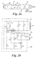
- FIGS. 2a and 2b show the receiver and transmitter circuits 27, 28 of device 10 in more detail.
- the receiver includes a coupling coil 29, described in more detail below, designed to couple as much energy as possible from a magnetic field incident on the device 10 while it is in the GI tract.
- Coil 29 is connected to a tuner 30, that tunes the resonant frequency of the receiver and includes one or more tuning capacitors C1, C2 connected in parallel in a per se known manner.
- Tuner 30 is connected in series with resistor R1 defining heater 20 that is mounted on the surface 25a of pcb 25, in contact with thread 19.
- resistor R1 is connected in series with the remainder of receiver circuit 27 by means of a short circuit line 32 including a breakable link 31.
- Pcb 25 also includes a transmitter 28.
- Transmitter 28 includes a rectifier 33 that rectifies the oscillating currents in receiver 27 when the transmitter becomes operational.
- Transmitter 28 includes a per se known Hartly oscillator including oscillator feedback capacitor C3; transmitter frequency determining capacitors C4 and C6; d.c. supply capacitor C5; biasing resistors R2, R3 and R4; and switching transistor Q1.
- the outputs of the frequency determining parts C4, C6 of the oscillator are transmitted externally of the mammal by series antennae 34, 35.
- Transmitter 28 may optionally include a transmitter coil similar to or constituted by coil 29.
- Line 32 initially isolates transmitter 28 from any current induced in receiver 27, until breakable line 31 is broken in a manner described below. At that point direct current, rectified by rectifier 33, flows in transmitter 28 and produces an oscillating output by virtue of the presence of the Hartly oscillator circuit.
- receiver tuning capacitors C1 and C2 and the oscillator frequency determining capacitors C4 and C6 are chosen so that the resonant frequency of receiver circuit 30 is distinct from the output frequency of the transmitter 28, thereby avoiding confusion between the fields input to and output by the device 10.
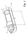
- FIG. 3 one arrangement of the receiver coupling coil 29 is shown, in which the coiled antenna wire 29 is embedded in the cylindrical outer wall of the housing 11 of the device 10. This arrangement is advantageously space-efficient and provides an air core for the wire 29.
- the diameter of the coil defined by wire 29 is 8-12mm; and the length I from one end to the other of the coil is 10-20mm.
- the preferred wire diameter is 0.1mm-0.3mm and the antenna coil preferably has 60-100 turns.
- the ferrite core and coil form a central axial rod rigidly connecting the two discs 16a, 16b to define a bobbin-like member.
- the discs 16a, 16b have sliding seals 16c that slide along the hollow interior of the capsule body.
- the space between the discs 16a, 16b forms the reservoir 12 for the substance 12a to be dispensed.
- the disc 16a adjacent to the pcb 25 acts as the piston and the disc 16b at the other end acts as a cap.
- a compression spring 50 acts between pcb 25 and disc 16a and tends to drive the bobbin-like structure out of the openable end 11a of the housing 11.
- a latch and actuator mechanism similar to those of Figure 1 temporarily prevent expulsion of the bobbin-like structure and hence the substance 12a, in a manner similar to that described hereinabove in relation to Figure 1 .
- the tuning components and the latch mechanism are mounted on the bobbin separated from the substance to be released by the lower disc and seal or may be on the capsule body 11 and connected to the bobbin by fine wires. After the latch is activated and the spring 50 is released the whole of the bobbin is slid out of the open capsule end. This avoids the need to pressurise the capsule to push off the cap.
- the coil 29a in Figure 4 can be made of smaller diameter than the Figure 3 coil. Consequently the ferrite-cored coil 29a may be located as a discrete component within housing 11, as shown.
- the loops thereof preferably are spaced from any fluid within or surrounding the device by a distance of 0.1mm to 1mm. This minimises the capacitance effects of neighbouring fluids while maintaining compactness of the device 10.
- the ferrite core (when present) may be similarly isolated from fluids. The isolation may arise because of a coating on the outer surface of the coil/core combination 29a, 36 of Figure 4 .
- the ferrite core 36 includes an axial bore.
- the thread 19 extends along the bore and is anchored as shown to disc 16b.
- Figures 5a and 5b show a simplified form of an external field generator 40 according to the invention for transmitting power to a device such as, but not limited to, device 10 of Figure 1 .
- the field generator 40 includes a support in the form of a box-like housing 41 for each of a pair of field coils 42.
- the pair of coils 42 are in juxtaposition to one another and preferably but not essentially are dimensioned to define a Helmholtz pair.
- the location of and the spacing between the coils are such that, on positioning of a mammal between the coils, the coils lie on opposite sides of the abdomen of the mammal.
- the coils 42 are each connected to a source of oscillating electrical energy in the form of oscillator 43.
- a device 10 in the GI tract can be activated by the field generator 40 when the abdomen of the mammal is between the juxtaposed coils 42 and the oscillator switched on.
- the field generator 43 preferably generates a field that oscillates in the frequency range 1MHz-14MHz, and more preferably in the range 1MHz-3MHz.
- the field coils generate, inter alia, a near field magnetic field. This has a large energy content which is continually being exchanged between the field and the current in the coils. However, apart from resistive losses, no power is used to maintain this field until the receiver coil interacts with the field to extract energy. In this way the system is more like an air cored transformer rather than a radio transmitter.
- the housings 41 for the coils 42 optionally' include shielding.
- the function of the shielding is to provide a primary safety earth screen around the field coils to protect persons touching any exposed conductors resulting from mechanical damage to the insulation.
- the shielding is such as to avoid forming closed loops through which the field passes since these will induce current flow and reduce the field levels generated by the coils.
- the shielding may also be used to reduce the magnitude of the electric field outside the shielding generated by the coils and also the radio wave that is generated along with the magnetic field. This is advantageous in reducing any effect on other electronic equipment in the vicinity of the device. Should additional shielding be required then the coils, the oscillator and the user of the capsule could all be contained within an earthed mesh containment room or cubicle.
- the driver circuit for the coils 42 may include a capacitor oscillator that is separately connectable to each of the coils when the current supply to it is switched off. The inclusion of such an oscillator changes the resonant frequency of the said coil, thereby reducing or preventing resonance coupling from a further said coil when the generator is active to energise the further coil.
- FIG. 6 there is shown a further, and presently more preferred, embodiment of field generator 40 in which there are three pairs of the field coils 42.
- the pairs are arranged to generate three mutually skewed, and, more particularly, mutually orthogonal, oscillating magnetic fields, by virtue of arrangement of the coils as faces of a cube.
- the respective coils 42 may if desired be secured in a framework, that may also if desired support the shielding visible in Figure 5 , whereby a mammal may stand, sit or lie in the region between the coils.
- the framework may support at least one of the coils in a moveable fashion (eg. in a removable or hinged door or panel). This facilitates access to the inter-coil space, and in some embodiments permits adjustment of the spacing between the coils 42.
- FIG 7 there is shown another arrangement of the coils 42.
- the components are functionally similar to their counterparts in Figure 6 , but the coils of pair Cz1, Cz2 are formed as flat circular coils, whereas the coils Cx1, Cx2, Cy1 and Cy2 define arcuate planes that confer on the coil array as a whole a hollow cylindrical shape.
- This arrangement of coils may be supported on a frame as in the Figure 6 embodiment; or may if desired be supported on a wearable garment 41a schematically illustrated by dotted lines in Figure 7 .
- the embodiments of Figures 6 and 7 generate three mutually orthogonal, oscillating magnetic fields the flux lines at least one of which will intersect the antenna 29 of the device 10, regardless of the orientation of the device 10 in the GI tract.
- the energy in the magnetic field is efficiently transmitted to the device 10 to power its operation.
- the field generators of Figures 6 and 7 may of course include one or more of the aforesaid capacitor oscillators each connectable to a respective said coil 42 to prevent resonance coupling when the field generator is switched off.
- the coils 42 in the preferred embodiments each include eg. 1-4 turns of a large diameter (6mm diameter) hollow copper conductor with a wall thickness of 1 mm.
- Figures 8 and 9 show a mechanism, in accordance with the invention, for initiating transmission of a signal, by transmitter 28, indicative of discharge of the substance from reservoir 12 into the GI tract.
- Figures 8 and 9 show some of the components of device 10 (with others removed for clarity) in the vicinity of piston 16 and pcb 25.
- Figures 8 and 9 schematically show the spring 50 (not visible in Figures 1 and 2 ), that acts between rib 17 and the rear face 16a of piston 16 to provide an on-board energy source for powering movement of piston 16, in respectively its compressed ( Figure 8 ) and uncompressed ( Figure 9 ) conditions.
- Non-fusible thread 51 on exiting aperture 25b on rear face 25, is looped through the wire defining breakable link 31 shown schematically in Figure 2 .
- Non-fusible thread 51 is firmly anchored to rear face 25a at a location 52 spaced laterally from breakable link 31.
- the amount of slack in thread 51 in the pre-expulsion condition ( Figure 8 ) is adjustable by choosing the length of thread 51.
- the precise moment of rupturing of link 31, corresponding to a chosen point in the travel of piston 16, is adjustable.
- the thread 51 may also serve as a limit or restraint to movement of the piston 16, in the sense that when thread 51 tightens as shown in Figure 9 it prevents further movement of piston 16. This ensures that piston 16 and spring 50 are retained within device 10 even after expulsion of the substance.
- thread 51 is used both to rupture the link and restrain the piston a means is required to set the amount of movement of the piston which causes the link to rupture. This may be achieved by positioning the link so that as the thread tightens the force is applied at the appropriate time; or by attaching the thread to the link with adhesive at the appropriate location. It may also be preferable to use a restraining thread which has a higher temperature tolerance than the latch thread to ensure that even if the device is kept in a high field environment for a long time after operating there is no possibility that the restraining thread could be broken by the temperatures reached.
- a suitable thread could be made from materials such as kevlar, tungsten or carbon fibre.
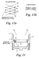
- Figure 13 shows a portion of the housing 11 of the Figure 3 device 10 (having an air cored coil).
- the piston 16 is visible at the end of its travel, following expulsion of the substance 12a from within the reservoir 12.
- a restraining ring 75 is secured on an inwardly directed shoulder 76 formed in the inner wall of housing 11 a short distance from the open end 13 of device 10. Ring 75 effectively reduces the diameter of the interior of housing 11, near to open end 13, to the extent that piston 16 is retained within reservoir 12 after use of the device 10.
- the edge 75a of ring 75 facing piston 16 is chamfered to reduce the impact force arising from contact of the piston 16 and ring 75.
- the chamfer shown at 75a also applies both axial and radial forces to the piston 16.
- the ring 75 may be manufactured from the same material as housing 11, in which case ring 75 may be welded, eg. using a solvent welding technique, to the housing 11.
- glue bonding may be used instead to secure the ring in place.
- the energy source when configured as a spring, it is desirable that the spring force is linear for as much of its travel as possible.
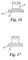
- Figures 16 and 17 show embodiments of the piston 16 used to expel the contents of reservoir 12 of capsule 10.
- the piston 16 of Figure 16 is intended for use when the reservoir 12 is charged with a substance in liquid form.
- piston 16 of Figure 16 includes an annular lip 160 that is upstanding from the periphery of end 161.
- Lip 160 tapers in the direction leading away from piston 16. At least lip 160, and in practice other parts of piston 16, are formed from a flexible material whereby in use of the piston 16 the outer periphery of lip 160 slidingly sealingly engages the inner, cylindrical surface of the reservoir 12.
- the tapered shape of lip 160 has been found to be particularly suited to the expulsion of liquid substances, since the lip is comparatively rigid. This confers good sealing properties, that prevent leakage of the liquid substance behind the piston.
- Figure 17 shows a similar piston 16 including a lip 162 that is parallel sided.
- a lip 162 is particularly suited to the expulsion of powdered or granular substances, that require higher expulsion forces.
- the parallel sided lip 162 that is more flexible than the tapered lip 160, reduces friction between the piston 16 and the reservoir 12 and hence assists expulsion of the powered substance.
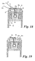
- Figures 18 and 19 show a device, such as device 10 of Figure 1 , in a state of partial assembly in order to illustrate a lost motion arrangement for breaking the breakable link 31 of pcb 25.
- device 10 has inserted in reservoir 12 a piston 16 that typically is as shown in Figure 16 or Figure 17 .
- anchor member 24 Extending transversely through the aperture in piston 16, anchor member 24 has secured thereto the thread 19 that passes through an aperture in pcb 25 to contact heater resistor 20 on the opposite side of pcb 25 to that of piston 16.
- a non-fusible thread 51 that in the preferred embodiment is made of silk, is looped around the anchor pin 24 and protrudes through the aperture in the rear face of piston 16 remote from face 161.
- Both the free ends 51 a, 51 b of the flexible thread 51 pass through the aperture in pcb 25; and one, 51 a of the ends passes under link 31 that forms a bridge interconnecting two parts of the surface of pcb 25.
- ends 51a, 51 b are tied together, as shown in Figure 19 , in a firm knot 51 c so that thread 51 forms a loop that is interlooped with link 31.
- Knot 51 c is sealed with eg. cyanoacrylate or another biocompatible adhesive.
- thread 51 in its looped form is such that, before expulsion of the substance, the looped thread lies slack. Consequently it allows eg. 5mm of movement of piston 16 away from pcb on melting of thread 19.
- thread 51 and link 31 constitute a switch for switching the transmitter 28.
- the thread 51 is a switch member that interconnects the actuator mechanism and the switch, such that operation of the actuator mechanism causes the switch member to operate the switch.
- heater resistor 20 is secured on projection 180. This arrangement facilitates assembly of the device 10 since it is an easy matter, on compression of springs 50a and 50b, to pass thread 19 over projection 180 to engage resistor 20.
- the resistors of the receiver and transmitter lie respectively on opposite surfaces 25a and 25b of pcb 25. This assists in dissipation of heat from the pcb. Of further assistance in dissipating heat is the perforating of the pcb 25 in the vicinity of each resistor.
- the reservoir 12 is charged with a non-therapeutic, non-diagnostic substance to be released and the latch set. These steps can take place during or after manufacture of the device 10, depending on the precise design of the device and its intended use.
- the device 10 is (optionally within the scope of the invention as claimed) ingested by a mammal under investigation. Its progress along the GI tract is monitored, eg. using a tracking technique as disclosed herein. When the device 10 reaches a chosen location in the GI tract an apparatus such as that shown in Figures 5 , 6 or 7 is operated to activate the device 10. The device 10 expels the substance 12a from reservoir 12 and the transmitter sends a signal that may be detected and processed as desired by external circuitry.
- the substance 12a typically may be a non-therapeutic, non-diagnostic substance whose efficacy at the chosen GI tract site is under investigation.
- the substance 12a may be a therapeutic or diagnostic agent.
Landscapes
- Health & Medical Sciences (AREA)
- Life Sciences & Earth Sciences (AREA)
- Engineering & Computer Science (AREA)
- Public Health (AREA)
- Veterinary Medicine (AREA)
- Anesthesiology (AREA)
- Biomedical Technology (AREA)
- Heart & Thoracic Surgery (AREA)
- Hematology (AREA)
- Animal Behavior & Ethology (AREA)
- General Health & Medical Sciences (AREA)
- Bioinformatics & Cheminformatics (AREA)
- Pulmonology (AREA)
- Chemical & Material Sciences (AREA)
- Biophysics (AREA)
- Medicinal Chemistry (AREA)
- Infusion, Injection, And Reservoir Apparatuses (AREA)
- Radiation-Therapy Devices (AREA)
- Measurement Of The Respiration, Hearing Ability, Form, And Blood Characteristics Of Living Organisms (AREA)
- Medicines Containing Material From Animals Or Micro-Organisms (AREA)
- Medicinal Preparation (AREA)
- Seal Device For Vehicle (AREA)
- Eye Examination Apparatus (AREA)
- Coloring Foods And Improving Nutritive Qualities (AREA)
- Surgical Instruments (AREA)
- Medicines Containing Plant Substances (AREA)
- Medicines That Contain Protein Lipid Enzymes And Other Medicines (AREA)
- Control Of Vending Devices And Auxiliary Devices For Vending Devices (AREA)
- Thermotherapy And Cooling Therapy Devices (AREA)
- Confectionery (AREA)
Claims (16)
- Einnehmbare Vorrichtung zum Verabreichen einer Substanz an einen gewählten oder identifizierbaren Ort in dem Verdauungstrakt eines Menschen oder Tiers, mit
einem öffenbaren Behälter für die Substanz, der gegen ein Austreten der Substanz abdichtbar ist;
einem Aktuatormechanismus zum Öffnen des Behälters,
einer Energiequelle, die derart wirkend angeschlossen ist, dass sie den Aktuatormechanismus mit Energie versorgt;
einer lösbaren Klinke zum kontrollierbaren Schalten der Anwendung von Leistung von der Energiequelle auf den Aktuator; und
einem Empfänger für elektromagnetische Strahlung zum Betätigen der Klinke, wenn der Empfänger Strahlung innerhalb eines vorgegebenen charakteristischen Bereichs detektiert; und einem Sender für elektromagnetische Strahlung zum Senden eines Signals, das den Betrieb der Vorrichtung anzeigt,
wobei der Behälter eine Austrittsöffnung für die Substanz umfasst, die von einem Verschlusselement verschlossen ist, das relativ zu der Öffnung abdichtend gehalten wird, wobei die Austrittsöffnung durch Betrieb des Aktuatormechanismus öffenbar ist; wobei(i) die Klinke thermisch betätigt wird;(ii) die Energiequelle durch die Klinke in einem Zustand potentieller Energie gehalten wird, bis die Klinke arbeitet; und(iii) die Vorrichtung eine Heizung zum Erhitzen der Klinke umfasst, wodurch, wenn der Empfänger die Strahlung detektiert, der Empfänger arbeitet, um die Heizung zu betreiben und dadurch die Klinke freizugeben, wodurch das Austreiben der Substanz aus dem Behälter erlaubt wird; dadurch gekennzeichnet, dass:die Vorrichtung auch eine Rückhaltung umfasst, die verwendbar ist, um den Betrieb des Aktuatormechanismus zu begrenzen; und dass beim Freigeben der Klinke die Rückhaltung einen Schalter betätigt, um den Sender für die Übermittlung des Signals zu aktivieren. - Vorrichtung nach Anspruch 1, wobei:der Aktuartormechanismus ein bewegliches Element umfasst, das unter Antrieb durch elektrische Energie von der Energiequelle beweglich ist, um das Ausstoßen der Substanz aus dem Behälter zu fördern;die Rückhaltung ein flexibles Element umfasst, dass das bewegliche Element und einen Anker verbindet, der relativ zu dem Rest der Vorrichtung festliegt; undder Schalter ein zerbrechliches elektrisch leitfähiges Element umfasst, wobei das flexible Element und das zerbrechliche Element wechselseitig in Angriff bringbar sind, wobei bei Bewegung des beweglichen Elements, die ausreichend ist, um die Substanz teilweise oder vollständig auszutreiben oder ihre Austreibung aus dem Reservoir zu initiieren, das flexible Element an dem zerbrechlichen Element angreift und dieses zerbricht, um den Schalter zu betätigen.
- Vorrichtung nach Anspruch 1 oder 2, wobei der Aktuatormechanismus einen Kolben umfasst, der unter Antrieb durch die Energiequelle beweglich ist, um die Substanz in dem Reservoir zusammenzudrücken, um ihr Austreiben daraus zu fördern.
- Vorrichtung nach einem der Ansprüche 1 bis 3, wobei der Sender einen Resonanzkreis umfasst, der anschließbar ist, um Energie von dem Empfänger zu ziehen; und das zerbrechliche Element ein Kurzschlusskontakt ist, der den Resonanzkreis elektrisch von dem Empfänger isoliert, bis das flexible Element das zerbrechliche Element bricht.
- Vorrichtung nach einem der Ansprüche 1 bis 4, wobei die Länge des flexiblen Elements derart ist, dass sie den Weg des beweglichen Elements auf ein gewähltes Maximum beschränkt.
- Vorrichtung nach einem der Ansprüche 1 bis 5, wobei die Rückhaltung und der Schalter so dimensioniert und/oder angeordnet sind, dass die Rückhaltung den Schalter zu einem Zeitpunkt bestätigt, der einem vorgegebenen Maß an Bewegung des beweglichen Elements entspricht.
- Einnehmbare Vorrichtung zum Verabreichen einer Substanz an einen gewählten oder identifizierbaren Ort in dem Verdauungstrakt eines Menschen oder Tiers, mit
einem öffenbaren Behälter für die Substanz, der gegen ein Austreten der Substanz abdichtbar ist;
einem Aktuatormechanismus zum Öffnen des Behälters,
einer Energiequelle, die derart wirkend angeschlossen ist, dass sie den Aktuatormechanismus mit Energie versorgt;
einer lösbaren Klinke zum kontrollierbaren Schalten der Anwendung von Leistung von der Energiequelle auf den Aktuator; und
einem Empfänger für elektromagnetische Strahlung zum Betätigen der Klinke, wenn der Empfänger Strahlung innerhalb eines vorgegebenen charakteristischen Bereichs detektiert; und einem Sender für elektromagnetische Strahlung zum Senden eines Signals, das den Betrieb der Vorrichtung anzeigt,
wobei der Behälter eine Austrittsöffnung für die Substanz umfasst, die von einem Verschlusselement verschlossen ist, das relativ zu der Öffnung abdichtend gehalten wird, wobei die Austrittsöffnung durch Betrieb des Aktuatormechanismus öffenbar ist; wobei(i) die Klinke thermisch betätigt wird;(ii) die Energiequelle durch die Klinke in einem Zustand potentieller Energie gehalten wird, bis die Klinke arbeitet; und(iii) die Vorrichtung eine Heizung zum Erhitzen der Klinke umfasst, wodurch, wenn der Empfänger die Strahlung detektiert, der Empfänger arbeitet, um die Heizung zu betreiben und dadurch die Klinke freizugeben, wodurch das Austreiben der Substanz aus dem Behälter erlaubt wird; durch gekennzeichnet, dass die Vorrichtung weiterhin umfasst(a) eine Rückhaltung, die betätigbar ist, um den Betrieb des Aktuatormechanismus zu begrenzen;(b) einen Schalter zum schaltenden Betätigen des Senders; und(c) ein Schaltelement, das den Aktuatormechanismus und den Schalter derart wirkend miteinander verbindet, dass der Betrieb des Aktuatormechanismus dazu führt, dass das Schaltelement den Schalter betätigt. - Vorrichtung nach Anspruch 7, wobei der Aktuatormechanismus ein bewegliches Element und das Schaltelement eine Totganganordnung umfasst, wodurch sich das bewegliche Element bewegt, bevor das Schaltelement den Schalter betätigt.
- Vorrichtung nach Anspruch 8, wobei das Schaltelement das bewegliche Element und den Schalter verbindet und ein schlaffes flexibles Element umfasst, dessen Schlaffheit die Totganganordnung bereitstellt.
- Vorrichtung nach Anspruch 9, die eine Leiterplatte mit einem an voneinander beabstandeten Orten daran gesichert zerbrechlichen Draht aufweist, um den Schalter zu definieren, wobei die Leiterplatte mit Löchern versehen ist und der Schalter und das bewegliche Element jeweils auf einander gegenüberliegenden Seiten der Leiterplatte liegen; und wobei das Schaltelement einen schlaffen flexiblen Faden umfasst, der durch ein Loch in der Leiterplatte hindurch tritt und eine Schlaufe umfasst, die den brechbaren Draht umschließt, wobei der Faden an dem beweglichen Element gesichert ist, wodurch der Faden gespannt wird, so dass die Schlaufe den zerbrechlichen Draht bricht, wenn sich das bewegliche Element bewegt.
- Vorrichtung nach Anspruch 7 oder einem der davon abhängigen Ansprüche, die eine Leiterplatte umfasst, die den Empfänger und den Sender trägt, wobei der Empfänger und Sender jeweils eine an der Leiterplatte gesicherte Widerstandsspur umfassen, wobei die Widerstandsspur des Senders und des Empfängers jeweils auf einander gegenüberliegenden Seiten der Leiterplatte liegen.
- Vorrichtung nach Anspruch 11, wobei die Leiterplatte ein oder mehrere Löcher in der Nähe jeder der Widerstandsspuren umfasst.
- Vorrichtung nach Anspruch 10 oder einem der davon abhängigen Ansprüche, wobei ein Vorsprung von einer Kante eines Lochs durch die Leiterplatte vorsteht und wobei die Klinke einen Faden mit genau bestimmtem Schmelzpunkt umfasst, dass das Aktuatorelement und den Vorsprung verbindet.
- Vorrichtung nach Anspruch 13, wobei die Heizung in Wärme übertragender Nähe zu dem Filament mit genau bestimmtem Schmelzpunkt an dem Vorsprung gesichert ist.
- Vorrichtung nach einem der Ansprüche 1 bis 14, wobei der Behälter derselben eine Ladung flüssiger, pulverförmiger oder fester, nicht-therapeutischer nicht-diagnostischer Substanz oder eine nicht-therapeutische nicht-diagnostische Suspension oder nicht-therapeutische nicht-diagnostische Lösung zum Freigeben in den Magen-Darm-Trakt eines Säugetiers umfasst.
- Vorrichtung nach einem der Ansprüche 1 bis 15, die eine Radioisotopmarkierung umfasst, die Strahlung erzeugt, welche detektierbar ist, um den Ort der Vorrichtung in dem Magen-Darm-Trakt eines Säugetiers anzuzeigen.
Applications Claiming Priority (3)
| Application Number | Priority Date | Filing Date | Title |
|---|---|---|---|
| GBGB9930000.6A GB9930000D0 (en) | 1999-12-21 | 1999-12-21 | An ingestible device |
| EP00985571A EP1239769A2 (de) | 1999-12-21 | 2000-12-14 | Einnehmbare vorrichtung zur freisetzung von substanzen an definierten orten des verdauungstraktes |
| EP03078778A EP1398052B1 (de) | 1999-12-21 | 2000-12-14 | Einnehmbare vorrichtung zur freisetzung von substanzen an definierten orten des verdauungstraktes |
Related Parent Applications (3)
| Application Number | Title | Priority Date | Filing Date |
|---|---|---|---|
| EP03078778A Division EP1398052B1 (de) | 1999-12-21 | 2000-12-14 | Einnehmbare vorrichtung zur freisetzung von substanzen an definierten orten des verdauungstraktes |
| EP00985571.9 Division | 2000-12-14 | ||
| EP03078778.2 Division | 2003-12-01 |
Publications (3)
| Publication Number | Publication Date |
|---|---|
| EP2016898A2 EP2016898A2 (de) | 2009-01-21 |
| EP2016898A3 EP2016898A3 (de) | 2009-04-08 |
| EP2016898B1 true EP2016898B1 (de) | 2010-07-07 |
Family
ID=10866613
Family Applications (3)
| Application Number | Title | Priority Date | Filing Date |
|---|---|---|---|
| EP03078778A Expired - Lifetime EP1398052B1 (de) | 1999-12-21 | 2000-12-14 | Einnehmbare vorrichtung zur freisetzung von substanzen an definierten orten des verdauungstraktes |
| EP08075824A Expired - Lifetime EP2016898B1 (de) | 1999-12-21 | 2000-12-14 | Einnehmbare Vorrichtung zur Freisetzung von Substanzen an definierten Orten des Verdauungstraktes |
| EP00985571A Withdrawn EP1239769A2 (de) | 1999-12-21 | 2000-12-14 | Einnehmbare vorrichtung zur freisetzung von substanzen an definierten orten des verdauungstraktes |
Family Applications Before (1)
| Application Number | Title | Priority Date | Filing Date |
|---|---|---|---|
| EP03078778A Expired - Lifetime EP1398052B1 (de) | 1999-12-21 | 2000-12-14 | Einnehmbare vorrichtung zur freisetzung von substanzen an definierten orten des verdauungstraktes |
Family Applications After (1)
| Application Number | Title | Priority Date | Filing Date |
|---|---|---|---|
| EP00985571A Withdrawn EP1239769A2 (de) | 1999-12-21 | 2000-12-14 | Einnehmbare vorrichtung zur freisetzung von substanzen an definierten orten des verdauungstraktes |
Country Status (10)
| Country | Link |
|---|---|
| US (3) | US6632216B2 (de) |
| EP (3) | EP1398052B1 (de) |
| JP (1) | JP2003517902A (de) |
| AT (2) | ATE423506T1 (de) |
| AU (1) | AU2198201A (de) |
| CA (1) | CA2390032C (de) |
| DE (2) | DE60044656D1 (de) |
| DK (2) | DK1398052T3 (de) |
| GB (1) | GB9930000D0 (de) |
| WO (1) | WO2001045789A2 (de) |
Families Citing this family (301)
| Publication number | Priority date | Publication date | Assignee | Title |
|---|---|---|---|---|
| US8636648B2 (en) * | 1999-03-01 | 2014-01-28 | West View Research, Llc | Endoscopic smart probe |
| US10973397B2 (en) | 1999-03-01 | 2021-04-13 | West View Research, Llc | Computerized information collection and processing apparatus |
| GB9930000D0 (en) * | 1999-12-21 | 2000-02-09 | Phaeton Research Ltd | An ingestible device |
| GB9930001D0 (en) * | 1999-12-21 | 2000-02-09 | Phaeton Research Ltd | An ingestible device |
| US8909325B2 (en) | 2000-08-21 | 2014-12-09 | Biosensors International Group, Ltd. | Radioactive emission detector equipped with a position tracking system and utilization thereof with medical systems and in medical procedures |
| US7826889B2 (en) | 2000-08-21 | 2010-11-02 | Spectrum Dynamics Llc | Radioactive emission detector equipped with a position tracking system and utilization thereof with medical systems and in medical procedures |
| US8055329B2 (en) | 2001-01-22 | 2011-11-08 | Spectrum Dynamics Llc | Ingestible device for radioimaging of the gastrointestinal tract |
| US8489176B1 (en) | 2000-08-21 | 2013-07-16 | Spectrum Dynamics Llc | Radioactive emission detector equipped with a position tracking system and utilization thereof with medical systems and in medical procedures |
| US8565860B2 (en) | 2000-08-21 | 2013-10-22 | Biosensors International Group, Ltd. | Radioactive emission detector equipped with a position tracking system |
| WO2005119025A2 (en) | 2004-06-01 | 2005-12-15 | Spectrum Dynamics Llc | Radioactive-emission-measurement optimization to specific body structures |
| US8036731B2 (en) * | 2001-01-22 | 2011-10-11 | Spectrum Dynamics Llc | Ingestible pill for diagnosing a gastrointestinal tract |
| WO2002102224A2 (en) * | 2001-06-18 | 2002-12-27 | Given Imaging Ltd. | In vivo sensing device with a circuit board having rigid sections and flexible sections |
| US7160258B2 (en) | 2001-06-26 | 2007-01-09 | Entrack, Inc. | Capsule and method for treating or diagnosing the intestinal tract |
| US6958767B2 (en) * | 2002-01-31 | 2005-10-25 | Deepsea Power & Light Company | Video pipe inspection system employing non-rotating cable storage drum |
| US7797033B2 (en) * | 2002-04-08 | 2010-09-14 | Smart Pill Corporation | Method of using, and determining location of, an ingestible capsule |
| US20040193229A1 (en) * | 2002-05-17 | 2004-09-30 | Medtronic, Inc. | Gastric electrical stimulation for treatment of gastro-esophageal reflux disease |
| US7001329B2 (en) * | 2002-07-23 | 2006-02-21 | Pentax Corporation | Capsule endoscope guidance system, capsule endoscope holder, and capsule endoscope |
| AU2003287392A1 (en) * | 2002-10-31 | 2004-06-07 | Kamran Mohseni | Guided capsule for wireless endoscopy, biopsy, and drug delivery |
| EP1573495B1 (de) * | 2002-11-04 | 2009-11-04 | Spectrum Dynamics LLC | Vorrichtungen und verfahren zur abbildungund dämpfungskorrektur |
| WO2004045374A2 (en) * | 2002-11-14 | 2004-06-03 | Ethicon Endo-Surgery, Inc. | Methods and devices for detecting tissue cells |
| US7833151B2 (en) * | 2002-12-26 | 2010-11-16 | Given Imaging Ltd. | In vivo imaging device with two imagers |
| CN100438937C (zh) * | 2002-12-30 | 2008-12-03 | 重庆大学 | 一种微型药物释放装置 |
| US20040267240A1 (en) * | 2003-01-29 | 2004-12-30 | Yossi Gross | Active drug delivery in the gastrointestinal tract |
| CA2514392A1 (en) * | 2003-01-29 | 2004-08-12 | E-Pill Pharma Ltd. | Active drug delivery in the gastrointestinal tract |
| DE10310825B3 (de) * | 2003-03-07 | 2004-08-19 | Fachhochschule Jena | Anordnung zur ferngesteuerten Freisetzung von Wirkstoffen |
| US7476224B2 (en) * | 2003-03-17 | 2009-01-13 | Petrakis Dennis N | Temperature responsive systems |
| US20070043263A1 (en) * | 2003-04-03 | 2007-02-22 | Wakefield Glenn M | Simultaneous magnetic control of multiple objects |
| US20040199054A1 (en) * | 2003-04-03 | 2004-10-07 | Wakefield Glenn Mark | Magnetically propelled capsule endoscopy |
| US7620454B2 (en) * | 2003-05-19 | 2009-11-17 | Medtronic, Inc. | Gastro-electric stimulation for reducing the acidity of gastric secretions or reducing the amounts thereof |
| US7742818B2 (en) * | 2003-05-19 | 2010-06-22 | Medtronic, Inc. | Gastro-electric stimulation for increasing the acidity of gastric secretions or increasing the amounts thereof |
| JP2005074031A (ja) * | 2003-09-01 | 2005-03-24 | Pentax Corp | カプセル内視鏡 |
| KR20140134338A (ko) | 2003-09-11 | 2014-11-21 | 테라노스, 인코포레이티드 | 피분석물의 모니터링 및 약물 전달을 위한 의료 기기 |
| EP1681010B1 (de) * | 2003-10-27 | 2012-10-10 | Olympus Corporation | Kapselartiges medizinprodukt |
| DE10359981A1 (de) * | 2003-12-19 | 2005-07-21 | Siemens Ag | System und Verfahren zur In Vivo Positions- und Orientierungsbestimmung einer Endoskopie-Kapsel bzw. eines Endoroboters im Rahmen einer kabellosen Endoskopie |
| US7968851B2 (en) | 2004-01-13 | 2011-06-28 | Spectrum Dynamics Llc | Dynamic spect camera |
| US8586932B2 (en) | 2004-11-09 | 2013-11-19 | Spectrum Dynamics Llc | System and method for radioactive emission measurement |
| US8571881B2 (en) | 2004-11-09 | 2013-10-29 | Spectrum Dynamics, Llc | Radiopharmaceutical dispensing, administration, and imaging |
| WO2005067383A2 (en) | 2004-01-13 | 2005-07-28 | Spectrum Dynamics Llc | Multi-dimensional image reconstruction |
| US9470801B2 (en) | 2004-01-13 | 2016-10-18 | Spectrum Dynamics Llc | Gating with anatomically varying durations |
| US10964075B2 (en) | 2004-01-13 | 2021-03-30 | Spectrum Dynamics Llc | Gating with anatomically varying durations |
| US9040016B2 (en) | 2004-01-13 | 2015-05-26 | Biosensors International Group, Ltd. | Diagnostic kit and methods for radioimaging myocardial perfusion |
| JP2005245937A (ja) * | 2004-03-08 | 2005-09-15 | Pentax Corp | 通信機能付き着衣、及び内視鏡システム |
| US20050195785A1 (en) * | 2004-03-08 | 2005-09-08 | Pentax Corporation | Image signal processing device |
| JP2005245938A (ja) * | 2004-03-08 | 2005-09-15 | Pentax Corp | 診断用着衣、診断用着衣システム、及び内視鏡システム |
| US7751866B2 (en) * | 2004-03-08 | 2010-07-06 | Olympus Corporation | Detecting system of position and posture of capsule medical device |
| JP4054319B2 (ja) * | 2004-03-29 | 2008-02-27 | オリンパス株式会社 | 電力供給装置 |
| US8361013B2 (en) | 2004-04-19 | 2013-01-29 | The Invention Science Fund I, Llc | Telescoping perfusion management system |
| US8337482B2 (en) | 2004-04-19 | 2012-12-25 | The Invention Science Fund I, Llc | System for perfusion management |
| US9011329B2 (en) | 2004-04-19 | 2015-04-21 | Searete Llc | Lumenally-active device |
| US7857767B2 (en) | 2004-04-19 | 2010-12-28 | Invention Science Fund I, Llc | Lumen-traveling device |
| US8024036B2 (en) | 2007-03-19 | 2011-09-20 | The Invention Science Fund I, Llc | Lumen-traveling biological interface device and method of use |
| US8353896B2 (en) | 2004-04-19 | 2013-01-15 | The Invention Science Fund I, Llc | Controllable release nasal system |
| US7850676B2 (en) | 2004-04-19 | 2010-12-14 | The Invention Science Fund I, Llc | System with a reservoir for perfusion management |
| US8512219B2 (en) | 2004-04-19 | 2013-08-20 | The Invention Science Fund I, Llc | Bioelectromagnetic interface system |
| US7998060B2 (en) | 2004-04-19 | 2011-08-16 | The Invention Science Fund I, Llc | Lumen-traveling delivery device |
| US8092549B2 (en) | 2004-09-24 | 2012-01-10 | The Invention Science Fund I, Llc | Ciliated stent-like-system |
| EP1766550A2 (de) | 2004-06-01 | 2007-03-28 | Spectrum Dynamics LLC | Verfahren zur ansichtsauswahl für messungen radioaktiver emission |
| US8518022B2 (en) | 2004-08-27 | 2013-08-27 | Medimetrics Personalized Drug Delivery, Inc. | Electronically and remotely controlled pill and system for delivering at least one medicament |
| AU2005301058A1 (en) * | 2004-11-05 | 2006-05-11 | Electronic Dietary Foods Inc. | Controlled degradation of expandable polymers in gastric volume reduction treatment |
| US8615405B2 (en) | 2004-11-09 | 2013-12-24 | Biosensors International Group, Ltd. | Imaging system customization using data from radiopharmaceutical-associated data carrier |
| US8606349B2 (en) | 2004-11-09 | 2013-12-10 | Biosensors International Group, Ltd. | Radioimaging using low dose isotope |
| US9316743B2 (en) | 2004-11-09 | 2016-04-19 | Biosensors International Group, Ltd. | System and method for radioactive emission measurement |
| US8423125B2 (en) | 2004-11-09 | 2013-04-16 | Spectrum Dynamics Llc | Radioimaging |
| US10136865B2 (en) | 2004-11-09 | 2018-11-27 | Spectrum Dynamics Medical Limited | Radioimaging using low dose isotope |
| WO2008059489A2 (en) | 2006-11-13 | 2008-05-22 | Spectrum Dynamics Llc | Radioimaging applications of and novel formulations of teboroxime |
| EP1827388A2 (de) * | 2004-12-14 | 2007-09-05 | E-Pill Pharma Ltd. | Lokale abgabe von arzneimitteln oder substanzen unter verwendung von elektronischer permeabilitätserhöhung |
| US7872235B2 (en) * | 2005-01-13 | 2011-01-18 | Spectrum Dynamics Llc | Multi-dimensional image reconstruction and analysis for expert-system diagnosis |
| US7585275B2 (en) * | 2005-01-18 | 2009-09-08 | Hoya Corporation | Capsule endoscope |
| US8836513B2 (en) | 2006-04-28 | 2014-09-16 | Proteus Digital Health, Inc. | Communication system incorporated in an ingestible product |
| US8802183B2 (en) | 2005-04-28 | 2014-08-12 | Proteus Digital Health, Inc. | Communication system with enhanced partial power source and method of manufacturing same |
| US8730031B2 (en) | 2005-04-28 | 2014-05-20 | Proteus Digital Health, Inc. | Communication system using an implantable device |
| US9198608B2 (en) | 2005-04-28 | 2015-12-01 | Proteus Digital Health, Inc. | Communication system incorporated in a container |
| CN102379684B (zh) * | 2005-04-28 | 2014-11-19 | 普罗透斯数字保健公司 | 药物信息系统 |
| US8912908B2 (en) | 2005-04-28 | 2014-12-16 | Proteus Digital Health, Inc. | Communication system with remote activation |
| KR101381331B1 (ko) | 2005-05-09 | 2014-04-04 | 테라노스, 인코포레이티드 | 현장진료 유체 시스템 및 그 용도 |
| RU2007146596A (ru) * | 2005-05-19 | 2009-06-27 | И-Пилл Фарма, Лтд. (Il) | Проглатываемое устройство для образования окиси азота в тканях |
| CN101217945B (zh) * | 2005-05-20 | 2012-07-11 | 陶氏环球技术有限责任公司 | 使用射频识别标签的口服用药依从性监视 |
| US8837793B2 (en) | 2005-07-19 | 2014-09-16 | Biosensors International Group, Ltd. | Reconstruction stabilizer and active vision |
| EP1908011B1 (de) | 2005-07-19 | 2013-09-04 | Spectrum Dynamics LLC | Rekonstruktionsstabilisierer und aktiv-vision |
| US9047746B1 (en) | 2005-07-20 | 2015-06-02 | Neil Euliano | Electronic medication compliance monitoring system and associated methods |
| CA2616010C (en) * | 2005-07-20 | 2013-11-05 | Neil R. Euliano | Medication compliance system and associated methods |
| EP1920418A4 (de) | 2005-09-01 | 2010-12-29 | Proteus Biomedical Inc | Implantierbare drahtlose kommunikationssysteme |
| US8273071B2 (en) | 2006-01-18 | 2012-09-25 | The Invention Science Fund I, Llc | Remote controller for substance delivery system |
| US8083710B2 (en) | 2006-03-09 | 2011-12-27 | The Invention Science Fund I, Llc | Acoustically controlled substance delivery device |
| US20070106271A1 (en) | 2005-11-09 | 2007-05-10 | Searete Llc, A Limited Liability Corporation | Remote control of substance delivery system |
| US7699834B2 (en) | 2005-11-09 | 2010-04-20 | Searete Llc | Method and system for control of osmotic pump device |
| US8617141B2 (en) | 2005-11-09 | 2013-12-31 | The Invention Science Fund I, Llc | Remote controlled in situ reaction device |
| US8936590B2 (en) | 2005-11-09 | 2015-01-20 | The Invention Science Fund I, Llc | Acoustically controlled reaction device |
| US8992511B2 (en) | 2005-11-09 | 2015-03-31 | The Invention Science Fund I, Llc | Acoustically controlled substance delivery device |
| US8062287B2 (en) * | 2005-12-22 | 2011-11-22 | Koninklijke Philips Electronics N V | Device for controlled release of chemical molecules |
| US8204500B2 (en) | 2005-12-28 | 2012-06-19 | Starhome Gmbh | Optimal voicemail deposit for roaming cellular telephony |
| US11287421B2 (en) | 2006-03-24 | 2022-03-29 | Labrador Diagnostics Llc | Systems and methods of sample processing and fluid control in a fluidic system |
| US8741230B2 (en) | 2006-03-24 | 2014-06-03 | Theranos, Inc. | Systems and methods of sample processing and fluid control in a fluidic system |
| US20120035437A1 (en) | 2006-04-12 | 2012-02-09 | Searete Llc, A Limited Liability Corporation Of The State Of Delaware | Navigation of a lumen traveling device toward a target |
| US8180436B2 (en) | 2006-04-12 | 2012-05-15 | The Invention Science Fund I, Llc | Systems for autofluorescent imaging and target ablation |
| DE102006019419B4 (de) * | 2006-04-26 | 2008-02-14 | Siemens Ag | Aktuator insbesondere eines Endoroboters |
| CA2650920C (en) | 2006-05-02 | 2016-10-18 | Proteus Biomedical, Inc. | Patient customized therapeutic regimens |
| US20070260174A1 (en) * | 2006-05-05 | 2007-11-08 | Searete Llc | Detecting a failure to maintain a regimen |
| US8007999B2 (en) | 2006-05-10 | 2011-08-30 | Theranos, Inc. | Real-time detection of influenza virus |
| US8894974B2 (en) | 2006-05-11 | 2014-11-25 | Spectrum Dynamics Llc | Radiopharmaceuticals for diagnosis and therapy |
| WO2007148238A1 (en) * | 2006-06-20 | 2007-12-27 | Koninklijke Philips Electronics, N.V. | Electronic capsule for treating gastrointestinal disease |
| US8597278B2 (en) * | 2006-06-23 | 2013-12-03 | MEDIMETRICS Personalized Drug Delivery B.V. | Medicament delivery system and process |
| US7601966B2 (en) | 2006-06-28 | 2009-10-13 | Spectrum Dynamics Llc | Imaging techniques for reducing blind spots |
| US8172762B2 (en) * | 2006-09-01 | 2012-05-08 | Proteus Biomedical, Inc. | Simultaneous blood flow and hematocrit sensor |
| US8588887B2 (en) * | 2006-09-06 | 2013-11-19 | Innurvation, Inc. | Ingestible low power sensor device and system for communicating with same |
| US20080064938A1 (en) * | 2006-09-08 | 2008-03-13 | Semler John R | Method of determining location of an ingested capsule |
| WO2008038199A1 (en) * | 2006-09-25 | 2008-04-03 | Koninklijke Philips Electronics, N.V. | Medicament delivery apparatus |
| US8012744B2 (en) | 2006-10-13 | 2011-09-06 | Theranos, Inc. | Reducing optical interference in a fluidic device |
| US8054140B2 (en) | 2006-10-17 | 2011-11-08 | Proteus Biomedical, Inc. | Low voltage oscillator for medical devices |
| MY158019A (en) | 2006-10-25 | 2016-08-30 | Proteus Digital Health Inc | Controlled activation ingestible identifier |
| WO2008053396A2 (en) * | 2006-10-31 | 2008-05-08 | Koninklijke Philips Electronics N.V. | Design of swallowable multi-nozzle, dosing device for releasing medicines in the gastrointesinal tract |
| US20080113391A1 (en) | 2006-11-14 | 2008-05-15 | Ian Gibbons | Detection and quantification of analytes in bodily fluids |
| US8718193B2 (en) | 2006-11-20 | 2014-05-06 | Proteus Digital Health, Inc. | Active signal processing personal health signal receivers |
| EP2086611B1 (de) * | 2006-11-21 | 2016-08-03 | Medimetrics Personalized Drug Delivery B.V. | Medikamentenabgabevorrichtung, kapsel und in vivo medikamentenabgabe oder diagnosesystem |
| RU2009123434A (ru) | 2006-11-21 | 2010-12-27 | Конинклейке Филипс Электроникс Н.В. (Nl) | Желудочная электронная капсула и система диагностики или доставки лекарственного средства внутрь живого организма |
| WO2008075362A2 (en) | 2006-12-20 | 2008-06-26 | Spectrum Dynamics Llc | A method, a system, and an apparatus for using and processing multidimensional data |
| PT3785599T (pt) | 2007-02-01 | 2022-10-21 | Otsuka Pharma Co Ltd | Sistemas de marcadores de eventos ingeríveis |
| CA2676280C (en) | 2007-02-14 | 2018-05-22 | Proteus Biomedical, Inc. | In-body power source having high surface area electrode |
| EP2119025A1 (de) | 2007-02-28 | 2009-11-18 | Rf Surgical Systems, Inc. | Verfahren, vorrichtung und artikel für den nachweis von transponder-markierten objekten, etwa bei chirurgischen eingriffen |
| WO2008112577A1 (en) | 2007-03-09 | 2008-09-18 | Proteus Biomedical, Inc. | In-body device having a multi-directional transmitter |
| US9270025B2 (en) | 2007-03-09 | 2016-02-23 | Proteus Digital Health, Inc. | In-body device having deployable antenna |
| US7696877B2 (en) | 2007-05-01 | 2010-04-13 | Rf Surgical Systems, Inc. | Method, apparatus and article for detection of transponder tagged objects, for example during surgery |
| US20080287833A1 (en) * | 2007-05-16 | 2008-11-20 | Semler John R | Method of evaluating gastroparesis using an ingestible capsule |
| US8115618B2 (en) | 2007-05-24 | 2012-02-14 | Proteus Biomedical, Inc. | RFID antenna for in-body device |
| US8158430B1 (en) | 2007-08-06 | 2012-04-17 | Theranos, Inc. | Systems and methods of fluidic sample processing |
| DK2192946T3 (da) | 2007-09-25 | 2022-11-21 | Otsuka Pharma Co Ltd | Kropsintern anordning med virtuel dipol signalforstærkning |
| US8088593B2 (en) | 2007-10-02 | 2012-01-03 | Theranos, Inc. | Modular point-of-care devices, systems, and uses thereof |
| US8303573B2 (en) * | 2007-10-17 | 2012-11-06 | The Invention Science Fund I, Llc | Medical or veterinary digestive tract utilization systems and methods |
| US20090105561A1 (en) * | 2007-10-17 | 2009-04-23 | Searete Llc, A Limited Liability Corporation Of The State Of Delaware | Medical or veterinary digestive tract utilization systems and methods |
| US8789536B2 (en) * | 2007-10-17 | 2014-07-29 | The Invention Science Fund I, Llc | Medical or veterinary digestive tract utilization systems and methods |
| US8707964B2 (en) * | 2007-10-31 | 2014-04-29 | The Invention Science Fund I, Llc | Medical or veterinary digestive tract utilization systems and methods |
| US8808276B2 (en) * | 2007-10-23 | 2014-08-19 | The Invention Science Fund I, Llc | Adaptive dispensation in a digestive tract |
| US8521253B2 (en) | 2007-10-29 | 2013-08-27 | Spectrum Dynamics Llc | Prostate imaging |
| US8109920B2 (en) * | 2007-10-31 | 2012-02-07 | The Invention Science Fund I, Llc | Medical or veterinary digestive tract utilization systems and methods |
| US8333754B2 (en) * | 2007-10-31 | 2012-12-18 | The Invention Science Fund I, Llc | Medical or veterinary digestive tract utilization systems and methods |
| US8808271B2 (en) * | 2007-10-31 | 2014-08-19 | The Invention Science Fund I, Llc | Medical or veterinary digestive tract utilization systems and methods |
| US20090163894A1 (en) * | 2007-10-31 | 2009-06-25 | Searete Llc, A Limited Liability Corporation Of The State Of Delaware | Medical or veterinary digestive tract utilization systems and methods |
| WO2009070773A1 (en) | 2007-11-27 | 2009-06-04 | Proteus Biomedical, Inc. | Transbody communication systems employing communication channels |
| US20090137866A1 (en) * | 2007-11-28 | 2009-05-28 | Searete Llc, A Limited Liability Corporation Of The State Delaware | Medical or veterinary digestive tract utilization systems and methods |
| US20090149839A1 (en) * | 2007-12-11 | 2009-06-11 | Hyde Roderick A | Treatment techniques using ingestible device |
| CN101945613B (zh) * | 2008-02-18 | 2014-08-13 | 皇家飞利浦电子股份有限公司 | 为患者用药 |
| US8258962B2 (en) | 2008-03-05 | 2012-09-04 | Proteus Biomedical, Inc. | Multi-mode communication ingestible event markers and systems, and methods of using the same |
| WO2009151946A2 (en) | 2008-05-27 | 2009-12-17 | Rf Surgical Systems, Inc. | Multi-modal transponder and method and apparatus to detect same |
| US8111162B2 (en) * | 2008-05-28 | 2012-02-07 | Rf Surgical Systems, Inc. | Method, apparatus and article for detection of transponder tagged objects, for example during surgery |
| CN102065930B (zh) * | 2008-06-19 | 2013-05-22 | 皇家飞利浦电子股份有限公司 | 用于在潮湿环境下传递粉末状药物的装置 |
| CN107049928A (zh) * | 2008-07-07 | 2017-08-18 | 皇家飞利浦电子股份有限公司 | 包括储药器的电子药丸 |
| CA3039236C (en) | 2008-07-08 | 2022-05-17 | Proteus Digital Health, Inc. | Ingestible event marker data framework |
| US8423122B2 (en) * | 2008-07-10 | 2013-04-16 | Given Imaging Ltd. | Localization of capsule with a synthetic source of quadrupoles and dipoles |
| CN104382598A (zh) | 2008-08-13 | 2015-03-04 | 普罗透斯数字保健公司 | 一种产生识别器的方法 |
| DE102008044994A1 (de) | 2008-08-29 | 2010-03-04 | Hochschule Offenburg | Elektronische Pille zur steuerbaren Abgabe einer Substanz, insbesondere eines Medikaments, in einem menschlichen oder tierischen Körper |
| US8264342B2 (en) | 2008-10-28 | 2012-09-11 | RF Surgical Systems, Inc | Method and apparatus to detect transponder tagged objects, for example during medical procedures |
| US8726911B2 (en) | 2008-10-28 | 2014-05-20 | Rf Surgical Systems, Inc. | Wirelessly detectable objects for use in medical procedures and methods of making same |
| KR101192690B1 (ko) | 2008-11-13 | 2012-10-19 | 프로테우스 디지털 헬스, 인코포레이티드 | 섭취 가능한 치료 활성화 시스템, 치료 장치 및 방법 |
| US8055334B2 (en) | 2008-12-11 | 2011-11-08 | Proteus Biomedical, Inc. | Evaluation of gastrointestinal function using portable electroviscerography systems and methods of using the same |
| US9659423B2 (en) | 2008-12-15 | 2017-05-23 | Proteus Digital Health, Inc. | Personal authentication apparatus system and method |
| TWI424832B (zh) | 2008-12-15 | 2014-02-01 | 波提亞斯數位康健公司 | 與身體有關的接收器及其方法 |
| US9439566B2 (en) | 2008-12-15 | 2016-09-13 | Proteus Digital Health, Inc. | Re-wearable wireless device |
| EP3395333A1 (de) | 2009-01-06 | 2018-10-31 | Proteus Digital Health, Inc. | System zur dosierten verabreichung von arzneimitteln |
| SG172846A1 (en) | 2009-01-06 | 2011-08-29 | Proteus Biomedical Inc | Ingestion-related biofeedback and personalized medical therapy method and system |
| WO2010111403A2 (en) | 2009-03-25 | 2010-09-30 | Proteus Biomedical, Inc. | Probablistic pharmacokinetic and pharmacodynamic modeling |
| CA2761033A1 (en) * | 2009-03-31 | 2010-10-14 | The Smartpill Corporation | Method of determining body exit of an ingested capsule |
| WO2010116312A1 (en) | 2009-04-07 | 2010-10-14 | Koninklijke Philips Electronics N.V. | Modular ingestible drug delivery capsule |
| DE102009017662B4 (de) | 2009-04-16 | 2016-11-10 | Hochschule Offenburg | Elektronische Pille zur steuerbaren Abgabe einer Substanz, insbesondere eines Medikaments, in einem menschlichen oder tierischen Körper |
| NZ596292A (en) * | 2009-04-28 | 2014-04-30 | Proteus Digital Health Inc | Highly reliable ingestible event markers and methods for using the same |
| US8414559B2 (en) | 2009-05-07 | 2013-04-09 | Rainbow Medical Ltd. | Gastroretentive duodenal pill |
| US20100286587A1 (en) * | 2009-05-07 | 2010-11-11 | Yossi Gross | Sublingual electrical drug delivery |
| US9149423B2 (en) | 2009-05-12 | 2015-10-06 | Proteus Digital Health, Inc. | Ingestible event markers comprising an ingestible component |
| US9457150B2 (en) * | 2009-06-01 | 2016-10-04 | Sanofi-Aventis Deutschland Gmbh | Biasing mechanism for a drug delivery device |
| DE102009024949B3 (de) | 2009-06-11 | 2011-02-24 | Andrä, Wilfried, Prof. Dr. | Anordnung zur ferngesteuerten Wirkstoff-Freisetzung |
| US8338788B2 (en) | 2009-07-29 | 2012-12-25 | Spectrum Dynamics Llc | Method and system of optimized volumetric imaging |
| AU2010279575B2 (en) | 2009-08-03 | 2016-05-05 | Incube Labs, Llc | Swallowable capsule and method for stimulating incretin production within the intestinal tract |
| JP5497176B2 (ja) | 2009-08-12 | 2014-05-21 | コーニンクレッカ フィリップス エヌ ヴェ | 圧縮可能な薬品貯槽を備える薬品送出装置 |
| WO2011022732A2 (en) | 2009-08-21 | 2011-02-24 | Proteus Biomedical, Inc. | Apparatus and method for measuring biochemical parameters |
| CN105808956A (zh) | 2009-10-19 | 2016-07-27 | 提拉诺斯公司 | 集成的健康数据采集和分析系统 |
| TWI517050B (zh) | 2009-11-04 | 2016-01-11 | 普羅托斯數位健康公司 | 供應鏈管理之系統 |
| US9226686B2 (en) | 2009-11-23 | 2016-01-05 | Rf Surgical Systems, Inc. | Method and apparatus to account for transponder tagged objects used during medical procedures |
| UA109424C2 (uk) | 2009-12-02 | 2015-08-25 | Фармацевтичний продукт, фармацевтична таблетка з електронним маркером і спосіб виготовлення фармацевтичної таблетки | |
| US8562589B2 (en) | 2009-12-24 | 2013-10-22 | Rani Therapeutics, Llc | Swallowable drug delivery device and method of delivery |
| BR112012019212A2 (pt) | 2010-02-01 | 2017-06-13 | Proteus Digital Health Inc | sistema de coleta de dados |
| EP2555737A4 (de) | 2010-04-07 | 2013-09-18 | Proteus Digital Health Inc | Verzehrbare miniaturvorrichtung |
| US9462962B2 (en) * | 2010-04-13 | 2016-10-11 | Biotronik Se & Co. Kg | Implant and applicator |
| TWI557672B (zh) | 2010-05-19 | 2016-11-11 | 波提亞斯數位康健公司 | 用於從製造商跟蹤藥物直到患者之電腦系統及電腦實施之方法、用於確認將藥物給予患者的設備及方法、患者介面裝置 |
| JP2014504902A (ja) | 2010-11-22 | 2014-02-27 | プロテウス デジタル ヘルス, インコーポレイテッド | 医薬品を有する摂取可能なデバイス |
| US9629799B2 (en) | 2010-12-23 | 2017-04-25 | Rani Therapeutics, Llc | Therapeutic agent preparations for delivery into a lumen of the intestinal tract using a swallowable drug delivery device |
| US9283179B2 (en) | 2010-12-23 | 2016-03-15 | Rani Therapeutics, Llc | GnRH preparations for delivery into a lumen of the intestinal tract using a swallowable drug delivery device |
| US9402807B2 (en) | 2010-12-23 | 2016-08-02 | Rani Therapeutics, Llc | Therapeutic agent preparations for delivery into a lumen of the intestinal tract using a swallowable drug delivery device |
| US9861683B2 (en) | 2010-12-23 | 2018-01-09 | Rani Therapeutics, Llc | Therapeutic agent preparations for delivery into a lumen of the intestinal tract using a swallowable drug delivery device |
| US8846040B2 (en) | 2010-12-23 | 2014-09-30 | Rani Therapeutics, Llc | Therapeutic agent preparations comprising etanercept for delivery into a lumen of the intestinal tract using a swallowable drug delivery device |
| US8980822B2 (en) | 2010-12-23 | 2015-03-17 | Rani Therapeutics, Llc | Therapeutic agent preparations comprising pramlintide for delivery into a lumen of the intestinal tract using a swallowable drug delivery device |
| US8969293B2 (en) | 2010-12-23 | 2015-03-03 | Rani Therapeutics, Llc | Therapeutic agent preparations comprising exenatide for delivery into a lumen of the intestinal tract using a swallowable drug delivery device |
| US8809271B2 (en) | 2010-12-23 | 2014-08-19 | Rani Therapeutics, Llc | Therapeutic agent preparations comprising liraglutide for delivery into a lumen of the intestinal tract using a swallowable drug delivery device |
| US8734429B2 (en) | 2010-12-23 | 2014-05-27 | Rani Therapeutics, Llc | Device, system and methods for the oral delivery of therapeutic compounds |
| US9415004B2 (en) | 2010-12-23 | 2016-08-16 | Rani Therapeutics, Llc | Therapeutic agent preparations for delivery into a lumen of the intestinal tract using a swallowable drug delivery device |
| US9402806B2 (en) | 2010-12-23 | 2016-08-02 | Rani Therapeutics, Llc | Therapeutic agent preparations for delivery into a lumen of the intestinal tract using a swallowable drug delivery device |
| US8809269B2 (en) | 2010-12-23 | 2014-08-19 | Rani Therapeutics, Llc | Therapeutic agent preparations comprising insulin for delivery into a lumen of the intestinal tract using a swallowable drug delivery device |
| US10639272B2 (en) | 2010-12-23 | 2020-05-05 | Rani Therapeutics, Llc | Methods for delivering etanercept preparations into a lumen of the intestinal tract using a swallowable drug delivery device |
| US8764733B2 (en) | 2010-12-23 | 2014-07-01 | Rani Therapeutics, Llc | Therapeutic agent preparations for delivery into a lumen of the intestinal tract using a swallowable drug delivery device |
| US9259386B2 (en) | 2010-12-23 | 2016-02-16 | Rani Therapeutics, Llc | Therapeutic preparation comprising somatostatin or somatostatin analogoue for delivery into a lumen of the intestinal tract using a swallowable drug delivery device |
| US9149617B2 (en) | 2010-12-23 | 2015-10-06 | Rani Therapeutics, Llc | Device, system and methods for the oral delivery of therapeutic compounds |
| US9284367B2 (en) | 2010-12-23 | 2016-03-15 | Rani Therapeutics, Llc | Therapeutic agent preparations for delivery into a lumen of the intestinal tract using a swallowable drug delivery device |
| CN106323875B (zh) | 2011-01-21 | 2019-07-09 | 西拉诺斯知识产权有限责任公司 | 样品使用最大化的系统和方法 |
| WO2012125425A2 (en) | 2011-03-11 | 2012-09-20 | Proteus Biomedical, Inc. | Wearable personal body associated device with various physical configurations |
| US9370628B2 (en) | 2011-06-05 | 2016-06-21 | University Of British Columbia | Wireless microactuators and control methods |
| US9756874B2 (en) | 2011-07-11 | 2017-09-12 | Proteus Digital Health, Inc. | Masticable ingestible product and communication system therefor |
| WO2015112603A1 (en) | 2014-01-21 | 2015-07-30 | Proteus Digital Health, Inc. | Masticable ingestible product and communication system therefor |
| CA2842952C (en) | 2011-07-21 | 2019-01-08 | Proteus Digital Health, Inc. | Mobile communication device, system, and method |
| US8816814B2 (en) | 2011-08-16 | 2014-08-26 | Elwha Llc | Systematic distillation of status data responsive to whether or not a wireless signal has been received and relating to regimen compliance |
| ITFI20110185A1 (it) | 2011-08-23 | 2013-02-24 | Fond Istituto Italiano Di Tecnologia | Capsula per terapia localizzata tramite cerotto endoluminale nel sistema gastrointestinale |
| JP5916031B2 (ja) * | 2011-09-05 | 2016-05-11 | 株式会社ミュー | 医療装置 |
| US9235683B2 (en) | 2011-11-09 | 2016-01-12 | Proteus Digital Health, Inc. | Apparatus, system, and method for managing adherence to a regimen |
| EP3725234A1 (de) | 2012-02-17 | 2020-10-21 | Progenity, Inc. | Einnehmbare medizinische vorrichtung |
| WO2013126178A1 (en) * | 2012-02-24 | 2013-08-29 | Capso Vision Inc | Power source control for medical capsules |
| US10264972B2 (en) * | 2012-05-21 | 2019-04-23 | International Business Machines Corporation | Dispensing drugs from a companion diagnostic linked smart pill |
| AU2013293234B2 (en) | 2012-07-23 | 2017-08-31 | Otsuka Pharmaceutical Co., Ltd. | Techniques for manufacturing ingestible event markers comprising an ingestible component |
| WO2014053352A1 (en) | 2012-10-03 | 2014-04-10 | Danmarks Tekniske Universitet | Ingestible capsule for remote controlled release of a substance |
| DK2910013T3 (en) | 2012-10-18 | 2018-08-06 | Proteus Digital Health Inc | Apparatus, system and method for adaptive optimization for power output and transmit power in a power source for a communication device |
| WO2014120669A1 (en) | 2013-01-29 | 2014-08-07 | Proteus Digital Health, Inc. | Highly-swellable polymeric films and compositions comprising the same |
| US10175376B2 (en) | 2013-03-15 | 2019-01-08 | Proteus Digital Health, Inc. | Metal detector apparatus, system, and method |
| PL2968071T3 (pl) * | 2013-03-15 | 2021-12-20 | Rani Therapeutics, Llc | Urządzenie do doustnego dostarczania związków leczniczych |
| WO2014151929A1 (en) | 2013-03-15 | 2014-09-25 | Proteus Digital Health, Inc. | Personal authentication apparatus system and method |
| GB201304738D0 (en) * | 2013-03-15 | 2013-05-01 | Mars Inc | Sampling Device |
| JP6511439B2 (ja) | 2013-06-04 | 2019-05-15 | プロテウス デジタル ヘルス, インコーポレイテッド | データ収集および転帰の査定のためのシステム、装置、および方法 |
| US9796576B2 (en) | 2013-08-30 | 2017-10-24 | Proteus Digital Health, Inc. | Container with electronically controlled interlock |
| CA2924815C (en) | 2013-09-20 | 2017-06-20 | Proteus Digital Health, Inc. | Methods, devices and systems for receiving and decoding a signal in the presence of noise using slices and warping |
| JP2016537924A (ja) | 2013-09-24 | 2016-12-01 | プロテウス デジタル ヘルス, インコーポレイテッド | 事前に正確に把握されていない周波数において受信された電磁信号に関する使用のための方法および装置 |
| US10084880B2 (en) | 2013-11-04 | 2018-09-25 | Proteus Digital Health, Inc. | Social media networking based on physiologic information |
| US10521561B1 (en) | 2013-12-17 | 2019-12-31 | Etectrx, Inc. | Electronic compliance system and associated methods |
| AU2014389444B2 (en) | 2014-03-31 | 2019-07-25 | Covidien Lp | Method, apparatus and article for detection of transponder tagged objects, for example during surgery |
| CN110680516A (zh) | 2014-03-31 | 2020-01-14 | 柯惠Lp公司 | 一种应答器检测装置 |
| US9662392B2 (en) | 2014-06-03 | 2017-05-30 | Pop Test Abuse Deterrent Technology Llc | Drug device configured for wireless communication |
| RU2711434C2 (ru) | 2014-09-17 | 2020-01-17 | Марс, Инкорпорейтед | Устройство для отбора проб и способ его использования |
| JP6740218B2 (ja) | 2014-09-17 | 2020-08-12 | マース インコーポレーテッドMars Incorporated | 装置 |
| EP3799776B1 (de) | 2014-09-25 | 2025-11-26 | BT Bidco, Inc. | Elektromechanische pillenvorrichtung mit lokalisationsfähigkeit |
| DE102014116537B4 (de) * | 2014-11-12 | 2024-05-29 | Infineon Technologies Ag | Funktionales Hautpflaster sowie System zum Überwachen eines Körpergesundheitsparameters |
| US9750923B2 (en) | 2014-11-19 | 2017-09-05 | Velóce Corporation | Wireless communications system integrating electronics into orally ingestible products for controlled release of active ingredients |
| US10912515B2 (en) * | 2014-11-19 | 2021-02-09 | Veloce Corporation | Wireless communications system integrating electronics into orally ingestible products for controlled release of active ingredients |
| US10660726B2 (en) | 2015-01-21 | 2020-05-26 | Covidien Lp | Sterilizable wirelessly detectable objects for use in medical procedures and methods of making same |
| WO2016118749A1 (en) | 2015-01-21 | 2016-07-28 | Covidien Lp | Detectable sponges for use in medical procedures and methods of making, packaging, and accounting for same |
| AU2016200113B2 (en) | 2015-01-21 | 2019-10-31 | Covidien Lp | Wirelessly detectable objects for use in medical procedures and methods of making same |
| AU2016200928B2 (en) | 2015-02-26 | 2020-11-12 | Covidien Lp | Apparatuses to physically couple transponder to objects, such as surgical objects, and methods of using same |
| US9690963B2 (en) | 2015-03-02 | 2017-06-27 | Covidien Lp | Hand-held dual spherical antenna system |
| USD775331S1 (en) | 2015-03-02 | 2016-12-27 | Covidien Lp | Hand-held antenna system |
| US10193209B2 (en) | 2015-04-06 | 2019-01-29 | Covidien Lp | Mat based antenna and heater system, for use during medical procedures |
| US11051543B2 (en) | 2015-07-21 | 2021-07-06 | Otsuka Pharmaceutical Co. Ltd. | Alginate on adhesive bilayer laminate film |
| AU2016365123B2 (en) | 2015-11-30 | 2020-11-19 | Jvd, Inc. | Medicine delivery and animal management systems |
| MX2019000888A (es) | 2016-07-22 | 2019-06-03 | Proteus Digital Health Inc | Percepcion y deteccion electromagnetica de marcadores de evento ingeribles. |
| EP4467182A3 (de) * | 2016-09-09 | 2025-01-15 | Biora Therapeutics, Inc. | Elektromechanische einnehmbare vorrichtung zur abgabe einer dispensierbaren substanz |
| WO2019186445A1 (en) | 2018-03-30 | 2019-10-03 | Vibrant Ltd. | Gastrointestinal treatment system including a vibrating capsule, and method of use thereof |
| GB2554354B (en) | 2016-09-21 | 2021-06-02 | Vibrant Ltd | Systems for adaptive treatment of disorders in the gastrointestinal tract |
| US11504024B2 (en) | 2018-03-30 | 2022-11-22 | Vibrant Ltd. | Gastrointestinal treatment system including a vibrating capsule, and method of use thereof |
| TWI735689B (zh) | 2016-10-26 | 2021-08-11 | 日商大塚製藥股份有限公司 | 製造含有可攝食性事件標記之膠囊之方法 |
| EP3551034A1 (de) | 2016-12-07 | 2019-10-16 | Progenity, Inc. | Verfahren, vorrichtungen und systeme zur detektion des magen-darm-trakts |
| WO2018111322A1 (en) * | 2016-12-14 | 2018-06-21 | Progenity Inc. | Methods and ingestible devices for the regio-specific release of integrin inhibitors at the site of gastrointestinal tract disease |
| CA3046019A1 (en) | 2016-12-14 | 2018-06-21 | Progenity Inc. | Treatment of a disease of the gastrointestinal tract with a tlr modulator |
| WO2018111324A1 (en) * | 2016-12-14 | 2018-06-21 | Progenity Inc. | Methods and ingestible devices for the regio-specific release of tlr agonists at the site of gastrointestinal tract disease |
| CN110072519A (zh) | 2016-12-14 | 2019-07-30 | 普罗根尼蒂公司 | 使用jak抑制剂治疗胃肠道疾病及装置 |
| US11134889B2 (en) | 2016-12-14 | 2021-10-05 | Progenity, Inc. | Treatment of a disease of the gastrointestinal tract with a SMAD7 inhibitor |
| WO2018111325A1 (en) * | 2016-12-14 | 2018-06-21 | Progenity Inc. | Methods and ingestible devices for the regio-specific release of il-6r inhibitors at the site of gastrointestinal tract disease |
| WO2018112255A1 (en) | 2016-12-14 | 2018-06-21 | Progenity Inc. | Treatment of a disease of the gastrointestinal tract with an immunosuppressant |
| CN110072551B (zh) | 2016-12-14 | 2023-05-23 | 比奥拉治疗股份有限公司 | 使用利用可摄入装置释放的il-12/il-23抑制剂治疗胃肠道疾病 |
| WO2018111326A1 (en) * | 2016-12-14 | 2018-06-21 | Progenity Inc. | Methods and ingestible devices for the regio-specific release of immunosuppressants at the site of gastrointestinal tract disease |
| WO2018111327A1 (en) * | 2016-12-14 | 2018-06-21 | Progenity Inc. | Methods and ingestible devices for the regio-specific release of jak inhibitors at the site of gastrointestinal tract disease |
| WO2018111328A1 (en) * | 2016-12-14 | 2018-06-21 | Progenity Inc. | Methods and ingestible devices for the regio-specific release of tnf inhibitors at the site of gastrointestinal tract disease |
| WO2018111323A1 (en) * | 2016-12-14 | 2018-06-21 | Progenity Inc. | Methods and ingestible devices for the regio-specific release of smad7 inhibitors at the site of gastrointestinal tract disease |
| WO2018111321A1 (en) * | 2016-12-14 | 2018-06-21 | Progenity Inc. | Methods and ingestible devices for the regio-specific release of il-12/il-23 inhibitors at the site of gastrointestinal tract disease |
| CN106823113A (zh) * | 2017-01-24 | 2017-06-13 | 武汉市瑞达源科技有限公司 | 一种医用胶囊装置 |
| US10905378B1 (en) | 2017-01-30 | 2021-02-02 | Vibrant Ltd | Method for treating gastroparesis using a vibrating ingestible capsule |
| US10888277B1 (en) | 2017-01-30 | 2021-01-12 | Vibrant Ltd | Method for treating diarrhea and reducing Bristol stool scores using a vibrating ingestible capsule |
| WO2018182641A1 (en) * | 2017-03-30 | 2018-10-04 | Progenity Inc. | Methods and ingestible devices for the regio-specific release of il-13 inhibitors at the site of gastrointestinal tract disease |
| WO2018182623A1 (en) * | 2017-03-30 | 2018-10-04 | Progenity Inc. | Methods and ingestible devices for the regio-specific release of chst15 inhibitors at the site of gastrointestinal tract disease |
| WO2018182612A1 (en) * | 2017-03-30 | 2018-10-04 | Progenity Inc. | Methods and ingestible devices for the regio-specific release of stem cells at the site of gastrointestinal tract disease |
| IL268900B2 (en) | 2017-03-31 | 2023-11-01 | Biora Therapeutics Inc | Localization systems and methods for an ingestible device |
| US11541015B2 (en) | 2017-05-17 | 2023-01-03 | Massachusetts Institute Of Technology | Self-righting systems, methods, and related components |
| EP3624892B1 (de) | 2017-05-17 | 2021-11-03 | Medtronic, Inc. | Antenne für implantierbare medizinvorrichtungen |
| CA3063711A1 (en) | 2017-05-17 | 2018-11-22 | Massachusetts Institute Of Technology | Self-righting systems, methods, and related components |
| US11439747B2 (en) * | 2017-10-04 | 2022-09-13 | Purdue Research Foundation | Drug delivery device and method |
| WO2019178071A1 (en) * | 2018-03-13 | 2019-09-19 | Progenity, Inc. | Ingestible device with relatively large payload volume |
| US12083303B2 (en) | 2019-01-21 | 2024-09-10 | Vibrant Ltd. | Device and method for delivering a flowable ingestible medicament into the gastrointestinal tract of a user |
| US11638678B1 (en) | 2018-04-09 | 2023-05-02 | Vibrant Ltd. | Vibrating capsule system and treatment method |
| US10537720B2 (en) | 2018-04-09 | 2020-01-21 | Vibrant Ltd. | Method of enhancing absorption of ingested medicaments for treatment of parkinsonism |
| US11020576B2 (en) | 2018-04-11 | 2021-06-01 | Jvd, Inc. | Medicine delivery and animal management systems |
| US11510590B1 (en) | 2018-05-07 | 2022-11-29 | Vibrant Ltd. | Methods and systems for treating gastrointestinal disorders |
| EP3793667A1 (de) | 2018-05-17 | 2021-03-24 | Massachusetts Institute of Technology | Systeme zur elektrischen stimulation |
| US10675248B2 (en) | 2018-08-14 | 2020-06-09 | Alma Therapeutics Ltd. | Expandable pill |
| US10928465B2 (en) * | 2018-11-02 | 2021-02-23 | Biosense Webster (Israel) Ltd. | Magnetic transmitters for a magnetic tracking system |
| WO2020106757A1 (en) * | 2018-11-19 | 2020-05-28 | Progenity, Inc. | Ingestible device for delivery of therapeutic agent to the gastrointestinal tract |
| CA3125091A1 (en) | 2019-01-03 | 2020-07-09 | Vibrant Ltd. | Device and method for delivering an ingestible medicament into the gastrointestinal tract of a user |
| US11786142B2 (en) * | 2019-01-11 | 2023-10-17 | Tokitae Llc | Ingestible RFID tag and reader system |
| GB201900780D0 (en) | 2019-01-21 | 2019-03-06 | Vibrant Ltd | Device and method for delivering a flowable ingestible medicament into the gastrointestinal tract of a user |
| WO2020160399A1 (en) | 2019-02-01 | 2020-08-06 | Massachusetts Institute Of Technology | Systems and methods for liquid injection |
| CN113329777B (zh) | 2019-02-01 | 2024-01-09 | 诺和诺德股份有限公司 | 具有致动机构的医疗装置 |
| GB201901470D0 (en) | 2019-02-04 | 2019-03-27 | Vibrant Ltd | Vibrating capsule for gastrointestinal treatment, and method of use thereof |
| KR102225352B1 (ko) * | 2019-02-19 | 2021-03-09 | 주식회사 인트로메딕 | 캡슐 내시경 |
| US11541216B2 (en) | 2019-11-21 | 2023-01-03 | Massachusetts Institute Of Technology | Methods for manufacturing tissue interfacing components |
| CN121197633A (zh) | 2019-12-13 | 2025-12-26 | 比特比德科有限责任公司 | 用于将治疗剂递送至胃肠道的可摄取装置 |
| US11620464B2 (en) | 2020-03-31 | 2023-04-04 | Covidien Lp | In-vivo introducible antenna for detection of RF tags |
| CN112516450A (zh) * | 2020-12-17 | 2021-03-19 | 曹飞东 | 一种新型触摸感应纳米晶头及使用方法 |
| US12626809B2 (en) | 2021-08-09 | 2026-05-12 | Covidien Lp | Inventory systems and methods for detecting and counting potentially retained surgical items |
| CN118632725A (zh) * | 2022-01-31 | 2024-09-10 | 诺和诺德股份有限公司 | 具有可分离的组织穿透构件的可摄取装置 |
| WO2023154257A1 (en) * | 2022-02-08 | 2023-08-17 | Trustees Of Tufts College | Ingestible capsule with beads for sampling content of the gastrointestinal tract |
| WO2025235985A1 (en) * | 2024-05-10 | 2025-11-13 | University Of Southern California | Ingestible sensor or treatment system and method with localization from magnetic-field generating wearable device |
Family Cites Families (23)
| Publication number | Priority date | Publication date | Assignee | Title |
|---|---|---|---|---|
| CH337989A (fr) * | 1957-04-09 | 1959-04-30 | Perrenoud Jean Pierre Dr | Capsule |
| US3485235A (en) * | 1967-12-04 | 1969-12-23 | Ronald Felson | Capsule for the study and treatment of the digestive tract |
| US3659600A (en) * | 1970-02-24 | 1972-05-02 | Estin Hans H | Magnetically operated capsule for administering drugs |
| US4239040A (en) * | 1976-10-19 | 1980-12-16 | Kabushiki Kaisha Daini Seikosha | Capsule for medical use |
| DE2928477C3 (de) * | 1979-07-14 | 1982-04-15 | Battelle-Institut E.V., 6000 Frankfurt | Vorrichtung zur Freisetzung von Substanzen an definierten Orten des Verdauungstraktes |
| JPS57156736A (en) * | 1981-03-23 | 1982-09-28 | Olympus Optical Co | Therapeutic capsule apparatus |
| JPS57163309A (en) * | 1981-04-01 | 1982-10-07 | Olympus Optical Co Ltd | Capsule apparatus for medical use |
| JPS58121938A (ja) * | 1982-01-14 | 1983-07-20 | 舟久保 煕康 | 試料採取カプセル |
| DE3339323C2 (de) * | 1983-10-29 | 1986-01-30 | Busch, Ulrich, 2000 Hamburg | Transportkapsel für Rohrleitungssysteme |
| DE3737104A1 (de) | 1987-11-02 | 1989-05-11 | Altenkirchener Kunststoff | Schlauchstueck aus elastischem, gut rueckstellbarem kunststoff und verfahren zu seiner herstellung |
| DE3820795A1 (de) * | 1988-06-20 | 1989-12-21 | Ingun Pruefmittelbau Gmbh | Gefederter kontaktstift zum pruefen von prueflingen |
| US4844076A (en) * | 1988-08-26 | 1989-07-04 | The Johns Hopkins University | Ingestible size continuously transmitting temperature monitoring pill |
| DE69009045T2 (de) | 1990-07-06 | 1994-10-06 | Miyarisan Pharma | Kapsel für medizinische Zwecke und Vorrichtung zu deren Aktivierung. |
| US5167626A (en) * | 1990-10-02 | 1992-12-01 | Glaxo Inc. | Medical capsule device actuated by radio-frequency (RF) signal |
| US5170801A (en) * | 1990-10-02 | 1992-12-15 | Glaxo Inc. | Medical capsule device actuated by radio-frequency (rf) signal |
| US5196002A (en) * | 1990-10-09 | 1993-03-23 | University Of Utah Research Foundation | Implantable drug delivery system with piston acutation |
| DE4037043A1 (de) * | 1990-11-19 | 1992-05-21 | Ulrich Dr Med Hanack | In lebewesen implantierbarer bimetallenergiewandler |
| US5217449A (en) * | 1990-12-11 | 1993-06-08 | Miyarisan Kabushiki Kaisha | Medical capsule and apparatus for activating the same |
| AU650113B2 (en) | 1991-04-05 | 1994-06-09 | Eli Lilly And Company | Sustained release capsule and formulations |
| US5279607A (en) | 1991-05-30 | 1994-01-18 | The State University Of New York | Telemetry capsule and process |
| US5639074A (en) * | 1996-03-05 | 1997-06-17 | Smalley Steel Ring Co. | Interlaced wave spring |
| US5951594A (en) * | 1998-04-28 | 1999-09-14 | Vitatron Medical B.V. | Air core antenna for implantable device and method of production |
| GB9930000D0 (en) * | 1999-12-21 | 2000-02-09 | Phaeton Research Ltd | An ingestible device |
-
1999
- 1999-12-21 GB GBGB9930000.6A patent/GB9930000D0/en not_active Ceased
-
2000
- 2000-12-14 EP EP03078778A patent/EP1398052B1/de not_active Expired - Lifetime
- 2000-12-14 AT AT03078778T patent/ATE423506T1/de not_active IP Right Cessation
- 2000-12-14 DE DE60044656T patent/DE60044656D1/de not_active Expired - Lifetime
- 2000-12-14 WO PCT/GB2000/004814 patent/WO2001045789A2/en not_active Ceased
- 2000-12-14 DK DK03078778T patent/DK1398052T3/da active
- 2000-12-14 CA CA2390032A patent/CA2390032C/en not_active Expired - Fee Related
- 2000-12-14 AU AU21982/01A patent/AU2198201A/en not_active Abandoned
- 2000-12-14 DE DE60041666T patent/DE60041666D1/de not_active Expired - Lifetime
- 2000-12-14 AT AT08075824T patent/ATE472970T1/de not_active IP Right Cessation
- 2000-12-14 EP EP08075824A patent/EP2016898B1/de not_active Expired - Lifetime
- 2000-12-14 EP EP00985571A patent/EP1239769A2/de not_active Withdrawn
- 2000-12-14 DK DK08075824.6T patent/DK2016898T3/da active
- 2000-12-14 JP JP2001546727A patent/JP2003517902A/ja active Pending
- 2000-12-20 US US09/742,936 patent/US6632216B2/en not_active Expired - Fee Related
-
2003
- 2003-06-27 US US10/607,721 patent/US7282045B2/en not_active Expired - Fee Related
-
2007
- 2007-07-30 US US11/830,689 patent/US7763014B2/en not_active Expired - Fee Related
Also Published As
| Publication number | Publication date |
|---|---|
| US20020055734A1 (en) | 2002-05-09 |
| AU2198201A (en) | 2001-07-03 |
| DE60041666D1 (de) | 2009-04-09 |
| WO2001045789A2 (en) | 2001-06-28 |
| US7282045B2 (en) | 2007-10-16 |
| US6632216B2 (en) | 2003-10-14 |
| JP2003517902A (ja) | 2003-06-03 |
| DK1398052T3 (da) | 2009-06-15 |
| DE60044656D1 (de) | 2010-08-19 |
| CA2390032A1 (en) | 2001-06-28 |
| EP2016898A3 (de) | 2009-04-08 |
| WO2001045789A3 (en) | 2001-11-08 |
| CA2390032C (en) | 2011-08-23 |
| EP1398052A2 (de) | 2004-03-17 |
| GB9930000D0 (en) | 2000-02-09 |
| EP1398052B1 (de) | 2009-02-25 |
| ATE472970T1 (de) | 2010-07-15 |
| EP1239769A2 (de) | 2002-09-18 |
| EP2016898A2 (de) | 2009-01-21 |
| US20050075559A1 (en) | 2005-04-07 |
| EP1398052A3 (de) | 2006-06-07 |
| US20070270630A1 (en) | 2007-11-22 |
| ATE423506T1 (de) | 2009-03-15 |
| DK2016898T3 (da) | 2010-10-25 |
| US7763014B2 (en) | 2010-07-27 |
Similar Documents
| Publication | Publication Date | Title |
|---|---|---|
| EP1398052B1 (de) | Einnehmbare vorrichtung zur freisetzung von substanzen an definierten orten des verdauungstraktes | |
| US5170801A (en) | Medical capsule device actuated by radio-frequency (rf) signal | |
| US10300259B2 (en) | Smart capsule with GI-tract-location-specific payload release | |
| US10098568B2 (en) | Computerized apparatus with ingestible probe | |
| US3485235A (en) | Capsule for the study and treatment of the digestive tract | |
| DE3065279D1 (en) | Swallowable capsule for the liberation of substances at distinct locations in the digestive tract | |
| US5882338A (en) | Syringes and syringe pumps | |
| CN102596081B (zh) | 射频消融导管和磁共振成像系统 | |
| JP6283677B2 (ja) | 外部知能を備える医薬給送カプセル | |
| EP1374933A1 (de) | Spritzen und Spritzenpumpen | |
| US6884239B2 (en) | Ingestible device for the release of substances at distinct locations in alimentary canal | |
| CN1304070C (zh) | 一种消化道药物定点释放装置 | |
| WO2012087668A1 (en) | Pill catchers | |
| WO2012087669A1 (en) | Pill catchers | |
| CN100588378C (zh) | 消化道遥控释药胶囊系统 | |
| CN200984246Y (zh) | 消化道遥控释药装置 | |
| US4796608A (en) | Shock wave generator for an apparatus for non-contacting disintegration of calculi in the body of a life form | |
| US4920955A (en) | Shock wave source | |
| RU2761368C2 (ru) | Устройство управления для электрохирургического инструмента | |
| CN106823113A (zh) | 一种医用胶囊装置 | |
| JPH0137613Y2 (de) | ||
| CA3039806C (en) | Single and multilayer bands and related methods | |
| EP3528884A1 (de) | Ein- und mehrschichtige bänder und zugehörige verfahren | |
| JP2004344550A (ja) | 殺菌装置 | |
| JPS63291343A (ja) | X線管冷却油収納装置 |
Legal Events
| Date | Code | Title | Description |
|---|---|---|---|
| PUAI | Public reference made under article 153(3) epc to a published international application that has entered the european phase |
Free format text: ORIGINAL CODE: 0009012 |
|
| 17P | Request for examination filed |
Effective date: 20081106 |
|
| AC | Divisional application: reference to earlier application |
Ref document number: 1239769 Country of ref document: EP Kind code of ref document: P Ref document number: 1398052 Country of ref document: EP Kind code of ref document: P |
|
| AK | Designated contracting states |
Kind code of ref document: A2 Designated state(s): AT BE CH CY DE DK ES FI FR GB GR IE IT LI LU MC NL PT SE TR |
|
| PUAL | Search report despatched |
Free format text: ORIGINAL CODE: 0009013 |
|
| AK | Designated contracting states |
Kind code of ref document: A3 Designated state(s): AT BE CH CY DE DK ES FI FR GB GR IE IT LI LU MC NL PT SE TR |
|
| RIN1 | Information on inventor provided before grant (corrected) |
Inventor name: HOUZEGO, PETER JOHN Inventor name: HIRST, PETER HANSON Inventor name: WILDING, IAN ROBERT Inventor name: WESTLAND, DUNCAN JAMES Inventor name: MORGAN, PETER NEIL |
|
| AKX | Designation fees paid |
Designated state(s): AT BE CH CY DE DK ES FI FR GB GR IE IT LI LU MC NL PT SE TR |
|
| GRAP | Despatch of communication of intention to grant a patent |
Free format text: ORIGINAL CODE: EPIDOSNIGR1 |
|
| GRAS | Grant fee paid |
Free format text: ORIGINAL CODE: EPIDOSNIGR3 |
|
| GRAA | (expected) grant |
Free format text: ORIGINAL CODE: 0009210 |
|
| AC | Divisional application: reference to earlier application |
Ref document number: 1239769 Country of ref document: EP Kind code of ref document: P Ref document number: 1398052 Country of ref document: EP Kind code of ref document: P |
|
| AK | Designated contracting states |
Kind code of ref document: B1 Designated state(s): AT BE CH CY DE DK ES FI FR GB GR IE IT LI LU MC NL PT SE TR |
|
| REG | Reference to a national code |
Ref country code: GB Ref legal event code: FG4D |
|
| REG | Reference to a national code |
Ref country code: CH Ref legal event code: EP Ref country code: CH Ref legal event code: NV Representative=s name: KIRKER & CIE S.A. |
|
| REG | Reference to a national code |
Ref country code: IE Ref legal event code: FG4D |
|
| REF | Corresponds to: |
Ref document number: 60044656 Country of ref document: DE Date of ref document: 20100819 Kind code of ref document: P |
|
| REG | Reference to a national code |
Ref country code: NL Ref legal event code: T3 |
|
| REG | Reference to a national code |
Ref country code: SE Ref legal event code: TRGR |
|
| REG | Reference to a national code |
Ref country code: DK Ref legal event code: T3 |
|
| PG25 | Lapsed in a contracting state [announced via postgrant information from national office to epo] |
Ref country code: AT Free format text: LAPSE BECAUSE OF FAILURE TO SUBMIT A TRANSLATION OF THE DESCRIPTION OR TO PAY THE FEE WITHIN THE PRESCRIBED TIME-LIMIT Effective date: 20100707 Ref country code: FI Free format text: LAPSE BECAUSE OF FAILURE TO SUBMIT A TRANSLATION OF THE DESCRIPTION OR TO PAY THE FEE WITHIN THE PRESCRIBED TIME-LIMIT Effective date: 20100707 |
|
| PG25 | Lapsed in a contracting state [announced via postgrant information from national office to epo] |
Ref country code: PT Free format text: LAPSE BECAUSE OF FAILURE TO SUBMIT A TRANSLATION OF THE DESCRIPTION OR TO PAY THE FEE WITHIN THE PRESCRIBED TIME-LIMIT Effective date: 20101108 Ref country code: CY Free format text: LAPSE BECAUSE OF FAILURE TO SUBMIT A TRANSLATION OF THE DESCRIPTION OR TO PAY THE FEE WITHIN THE PRESCRIBED TIME-LIMIT Effective date: 20100707 |
|
| PG25 | Lapsed in a contracting state [announced via postgrant information from national office to epo] |
Ref country code: GR Free format text: LAPSE BECAUSE OF FAILURE TO SUBMIT A TRANSLATION OF THE DESCRIPTION OR TO PAY THE FEE WITHIN THE PRESCRIBED TIME-LIMIT Effective date: 20101008 Ref country code: BE Free format text: LAPSE BECAUSE OF FAILURE TO SUBMIT A TRANSLATION OF THE DESCRIPTION OR TO PAY THE FEE WITHIN THE PRESCRIBED TIME-LIMIT Effective date: 20100707 |
|
| PLBE | No opposition filed within time limit |
Free format text: ORIGINAL CODE: 0009261 |
|
| STAA | Information on the status of an ep patent application or granted ep patent |
Free format text: STATUS: NO OPPOSITION FILED WITHIN TIME LIMIT |
|
| PG25 | Lapsed in a contracting state [announced via postgrant information from national office to epo] |
Ref country code: IT Free format text: LAPSE BECAUSE OF FAILURE TO SUBMIT A TRANSLATION OF THE DESCRIPTION OR TO PAY THE FEE WITHIN THE PRESCRIBED TIME-LIMIT Effective date: 20100707 |
|
| 26N | No opposition filed |
Effective date: 20110408 |
|
| PG25 | Lapsed in a contracting state [announced via postgrant information from national office to epo] |
Ref country code: ES Free format text: LAPSE BECAUSE OF FAILURE TO SUBMIT A TRANSLATION OF THE DESCRIPTION OR TO PAY THE FEE WITHIN THE PRESCRIBED TIME-LIMIT Effective date: 20101018 |
|
| REG | Reference to a national code |
Ref country code: DE Ref legal event code: R097 Ref document number: 60044656 Country of ref document: DE Effective date: 20110408 |
|
| PG25 | Lapsed in a contracting state [announced via postgrant information from national office to epo] |
Ref country code: MC Free format text: LAPSE BECAUSE OF NON-PAYMENT OF DUE FEES Effective date: 20101231 |
|
| PG25 | Lapsed in a contracting state [announced via postgrant information from national office to epo] |
Ref country code: LU Free format text: LAPSE BECAUSE OF NON-PAYMENT OF DUE FEES Effective date: 20101214 |
|
| PG25 | Lapsed in a contracting state [announced via postgrant information from national office to epo] |
Ref country code: TR Free format text: LAPSE BECAUSE OF FAILURE TO SUBMIT A TRANSLATION OF THE DESCRIPTION OR TO PAY THE FEE WITHIN THE PRESCRIBED TIME-LIMIT Effective date: 20100707 |
|
| PGFP | Annual fee paid to national office [announced via postgrant information from national office to epo] |
Ref country code: DK Payment date: 20131210 Year of fee payment: 14 |
|
| PGFP | Annual fee paid to national office [announced via postgrant information from national office to epo] |
Ref country code: IE Payment date: 20131210 Year of fee payment: 14 Ref country code: SE Payment date: 20131211 Year of fee payment: 14 Ref country code: DE Payment date: 20131211 Year of fee payment: 14 Ref country code: GB Payment date: 20131211 Year of fee payment: 14 Ref country code: CH Payment date: 20131212 Year of fee payment: 14 |
|
| PGFP | Annual fee paid to national office [announced via postgrant information from national office to epo] |
Ref country code: FR Payment date: 20131209 Year of fee payment: 14 Ref country code: NL Payment date: 20131210 Year of fee payment: 14 |
|
| REG | Reference to a national code |
Ref country code: DE Ref legal event code: R119 Ref document number: 60044656 Country of ref document: DE |
|
| REG | Reference to a national code |
Ref country code: DK Ref legal event code: EBP Effective date: 20141231 |
|
| REG | Reference to a national code |
Ref country code: NL Ref legal event code: V1 Effective date: 20150701 |
|
| REG | Reference to a national code |
Ref country code: NL Ref legal event code: V1 Effective date: 20150701 |
|
| PG25 | Lapsed in a contracting state [announced via postgrant information from national office to epo] |
Ref country code: SE Free format text: LAPSE BECAUSE OF NON-PAYMENT OF DUE FEES Effective date: 20141215 |
|
| REG | Reference to a national code |
Ref country code: CH Ref legal event code: PL |
|
| REG | Reference to a national code |
Ref country code: SE Ref legal event code: EUG |
|
| GBPC | Gb: european patent ceased through non-payment of renewal fee |
Effective date: 20141214 |
|
| REG | Reference to a national code |
Ref country code: IE Ref legal event code: MM4A |
|
| REG | Reference to a national code |
Ref country code: FR Ref legal event code: ST Effective date: 20150831 |
|
| PG25 | Lapsed in a contracting state [announced via postgrant information from national office to epo] |
Ref country code: NL Free format text: LAPSE BECAUSE OF NON-PAYMENT OF DUE FEES Effective date: 20150701 |
|
| PG25 | Lapsed in a contracting state [announced via postgrant information from national office to epo] |
Ref country code: CH Free format text: LAPSE BECAUSE OF NON-PAYMENT OF DUE FEES Effective date: 20141231 Ref country code: LI Free format text: LAPSE BECAUSE OF NON-PAYMENT OF DUE FEES Effective date: 20141231 Ref country code: DE Free format text: LAPSE BECAUSE OF NON-PAYMENT OF DUE FEES Effective date: 20150701 Ref country code: IE Free format text: LAPSE BECAUSE OF NON-PAYMENT OF DUE FEES Effective date: 20141214 Ref country code: GB Free format text: LAPSE BECAUSE OF NON-PAYMENT OF DUE FEES Effective date: 20141214 |
|
| PG25 | Lapsed in a contracting state [announced via postgrant information from national office to epo] |
Ref country code: FR Free format text: LAPSE BECAUSE OF NON-PAYMENT OF DUE FEES Effective date: 20141231 |
|
| PG25 | Lapsed in a contracting state [announced via postgrant information from national office to epo] |
Ref country code: DK Free format text: LAPSE BECAUSE OF NON-PAYMENT OF DUE FEES Effective date: 20141231 |