EP2016866A1 - Chair-type massage machine - Google Patents
Chair-type massage machine Download PDFInfo
- Publication number
- EP2016866A1 EP2016866A1 EP08012969A EP08012969A EP2016866A1 EP 2016866 A1 EP2016866 A1 EP 2016866A1 EP 08012969 A EP08012969 A EP 08012969A EP 08012969 A EP08012969 A EP 08012969A EP 2016866 A1 EP2016866 A1 EP 2016866A1
- Authority
- EP
- European Patent Office
- Prior art keywords
- backrest
- seat
- drive source
- link
- massage machine
- Prior art date
- Legal status (The legal status is an assumption and is not a legal conclusion. Google has not performed a legal analysis and makes no representation as to the accuracy of the status listed.)
- Granted
Links
- 230000002040 relaxant effect Effects 0.000 description 19
- 238000010276 construction Methods 0.000 description 6
- 230000000694 effects Effects 0.000 description 4
- 210000003489 abdominal muscle Anatomy 0.000 description 2
- 244000309466 calf Species 0.000 description 2
- 230000005484 gravity Effects 0.000 description 2
- 238000012986 modification Methods 0.000 description 2
- 230000004048 modification Effects 0.000 description 2
- 230000008602 contraction Effects 0.000 description 1
- 230000007423 decrease Effects 0.000 description 1
- 230000003292 diminished effect Effects 0.000 description 1
- 239000011347 resin Substances 0.000 description 1
- 229920005989 resin Polymers 0.000 description 1
Images


Classifications
-
- A—HUMAN NECESSITIES
- A47—FURNITURE; DOMESTIC ARTICLES OR APPLIANCES; COFFEE MILLS; SPICE MILLS; SUCTION CLEANERS IN GENERAL
- A47C—CHAIRS; SOFAS; BEDS
- A47C1/00—Chairs adapted for special purposes
- A47C1/02—Reclining or easy chairs
Definitions
- the present invention relates to massage machines of the chair type having a backrest and a seat which can be reclined. More particularly, the invention relates to chair-type massage machines comprising a backrest and a seat which can be reclined by a single drive source while permitting the person to be treated to hold a relaxed posture.
- chair-type massage machines are known in which a backrest and a seat have massage means and can be reclined.
- JP2003-289975A discloses such a massage machine comprising a reclining mechanism having independent drive sources provided for the respective backrest and seat so as to render each of the backrest and the seat reclinable independently of the other.
- the independent drive sources for the respective backrest and seat makes the reclining mechanism large-sized and complex to consequently make the chair-type massage machine greater in size and complex in the mode of control. Furthermore, the reclining mechanism comprising a plurality of drive sources encounters difficulty in positioning the backrest and the seat at a target angle in synchronism due, for example, to anomalies in the individual drive sources and variations in the load to be applied to the respective drive sources. The massage machine will then involve such an unnatural movement that one of the backrest and seat reaches the target angle with a delay after the other component has reached the target angle.
- An object of the present invention is to provide a chair-type massage machine comprising a backrest and a seat which can be reclined by a single drive source while permitting the user to hold a relaxed posture.
- the present invention provides a chair-type massage machine comprising a backrest for the back of the user to bear on, a seat for the user to sit in, and a reclining mechanism for pivotally moving the backrest and the seat.
- the reclining mechanism comprises a single drive source, and the drive source is coupled to the backrest and the seat by a link assembly.
- the link assembly is operable to pivotally move the backrest from a raised position to a reclined position via an intermediate position by operating the drive source, the seat being tiltable to raise a front end thereof when the backrest is pivotally moved from the raised position to the intermediate position, the seat being tiltable to lower the raised lower end thereof when the backrest is pivotally moved from the intermediate position to the reclined position.
- the present invention also provides a chair-type massage machine comprising a backrest for the back of the user to bear on, a seat for the user to sit in, and a reclining mechanism for pivotally moving the backrest and the seat.
- the reclining mechanism comprises a single drive source, the drive source being coupled to one of the backrest and the seat, the backrest or the seat having the drive source coupled thereto being pivotally movably supported.
- the backrest is connected to the seat by a link assembly having a joint portion, which is movable along a guide rail.
- the drive source is operable to move the joint portion of the link assembly along the guide rail, as coupled to the pivotal movement of the backrest or the seat, and to pivotally move the backrest from a raised position to a reclined position via an intermediate position, the guide rail having a curved guide face for tilting the seat to raise a front end thereof when the backrest is pivotally moved from the raised position to the intermediate position and for tilting the seat to lower the raised front end thereof when the backrest is pivotally moved from the intermediate position to the reclined position.
- the present invention further provides a chair-type massage machine wherein a base is provided with a backrest for the back of the user to bear on, a seat for the user to sit in, and a reclining mechanism for pivotally moving the backrest and the seat.
- the reclining mechanism comprises a single drive source, which is coupled to one of the backrest and the seat.
- the backrest or the seat having the drive source coupled thereto is pivotally movably supported.
- a link is pivoted at one end thereof to the backrest or the seat having the drive source coupled thereto, the link having the other end pivoted to a cam member supported by the base, the cam member being provided at a portion thereof with a cam face in bearing contact with the backrest or the seat not coupled to the drive source,
- the drive source is operable to cause the link to rotate the cam member and to pivotally move the backrest from a raised position to a reclined position via an intermediate position, the cam face being so shaped as to tilt the seat to raise a front end thereof when the backrest is pivotally moved from the raised position to the intermediate position and as to tilt the seat to lower the raised front end thereof when the backrest is pivotally moved from the intermediate position to the reclined position.
- any one of the forgoing chair-type massage machines a single drive source is provided for the reclining mechanism, which is therefore unlikely to become large-sized or complex. Furthermore, the use of the link assembly or the like assures a stabilized reclining movement free of variations.
- the present invention provides chair-type massage machines 10, which will be descried below with reference to the drawings.
- the massage machine 10 has a base 12 to be placed on the floor.
- the base 12 has supported thereon a seat 30 for the user to sit in and a backrest 20 for the back of the user to bear on.
- the seat and the backrest are pivotally movable by the reclining mechanism 40 to be described below.
- the backrest 20 comprises a backrest frame 22 and a cushion 23 or the like provided around the frame 22 and is provided in its interior with massage means 24 movable upward and downward by a lift unit 25 for massaging the shoulders, back, waist, etc. of the user.
- the seat 30 comprises a cushion 33 or the like provided around a seat frame 32 and is provided in its interior with an air bag or like massage means (not shown) as required.
- a leg portion 38 for placing thereon the legs of the user can be provided at the front end of the seat 30.
- the leg portion 38 shown in FIG. 1 is made integral with the seat 30, whereas the leg portion 38 may be adapted to accommodate therein the calves and the feet for a massage unit (not shown) to give a massage to the calves as shown in FIG. 6 or the like to be described later.
- the leg portion 38 may be made pivotally movable relative to the seat 30.
- the reclining mechanism 40 comprises a drive source 42 and a link assembly 50.
- the reclining mechanism 40 of the present invention is characterized in that both the backrest 20 and the seat 30 can be reclined by the single drive source 42. Furthermore, the backrest 20 and the seat 30 can be reclined while permitting the user to hold a relaxed posture.
- the expression that the user as positioned in a relaxed posture refers to such a state of the user that he or she is not particularly burdened on his body, or is not locally subjected to a force, or will not assume any objectionable posture when the backrest 20 is reclined with the user seated in the seat 30 with his back bearing on the backrest 20. If the backrest 20 only is merely reclined without tilting the seat 30, an objectionable force is likely to act on the abdominal muscle or waist to reduce the massage effect.
- the backrest 20 and the seat 30 can be reclined so as to retain the following "relax angle" in accordance with the reclining angle of the backrest 20, so that the machine can be reclined while permitting the user to hold a relaxed state.
- the seat 30 is so tilted that the front end of the seat 30 is positioned at a slightly higher level above the floor than the rear end thereof. This enables the user to seat deep in the seat 30 and feel relaxed.
- the seat 30 is tilted with its front end moved up. This enables the user to follow the reclining movement of the backrest 20 and feel at ease without applying any force to the abdominal muscle.
- the backrest 20 is reclined to an intermediate value of the greatest reclining angle (hereinafter referred to as an "intermediate position"), the seat 30 is inclined greatest with its front end raised to the highest level.
- the seat 30 When the backrest 20 is reclined further from the intermediate position, the seat 30 is inclined with its front end moved down, and the seat 30 returns to the same angle as in the raised position upon the backrest 20 reaching the greatest reclining angle (hereinafter referred to as a "reclined position"), whereby the backrest 20 and the seat 30 are brought to a nearly flat state.
- the backrest 20 After the backrest 20 has moved past the intermediate position, the back of the body of the user is held fully in intimate contact with the backrest 20, with the center of gravity shifted toward the backrest 20.
- the massage operation to be subsequently performed can produce the greatest possible effect.
- the backrest 20 and the seat 30 can be returned from the flat state to the raised position through a movement reverse to the foregoing movement while permitting the user to remain relaxed, with the result that the massage effect given will not be nullified or diminished.
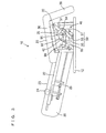
- FIG. 1 shows a single actuator serving as the single drive source 42 for the reclining mechanism 40.
- the actuator has one end connected to the upper end of a fixed frame 51 extending forwardly upward approximately from the center of the base 12. The other end of the actuator is connected to the lower end of the backrest 20.
- the contraction of the actuator in the chair-type massage machine 10 pulls the lower end of the backrest 20 as supported by the pivots 90, whereby the backrest 20 itself is reclined as shown, for example, in FIGS. 2 and 3 .
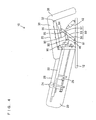
- the link assembly 50 can be composed of a plurality of links 53, 55 and 57 in combination.
- the link assembly 50 comprises a first link 53 pivoted as at 91 approximately to the center of the base 12, a second link 55 pivoted to a portion of the first link 53 close to the free end thereof and to the lower end of the backrest 20, respectively, as at 92, 93 for interconnecting the link 53 and the backrest 20, and a third link 57 pivoted to the free end extremity of the first link 53 and to a bracket 35 projecting from the bottom of the seat 30, respectively, as at 94, 95 for interconnecting the link 53 and the bracket 35.
- the present embodiment reclines with the backrest 20 and the seat 30 held at a relaxing angle, and the seat 30 is held approximately at the same level in the raised position of FIG. 1 and in the reclined position of FIG. 3 .
- the first link 53 and the third link 57 move symmetrically about a vertical line in FIG. 1 and FIG. 3 .
- the stroke length of the second link 55 operatively connected to the backrest 20 is so determined as to effect this movement. If the actuator serving as the drive source 42 has a sufficiently large stroke length, the pivot 92 between the second link 55 and the first link 53 can be positioned closer to the pivot 94 connecting the third link 57 to the first link 53, such that in an extreme case, pivots 92, 94 can be a common pivot.
- the highest level of the front end of the seat 30 is adjustable by shifting the position of the pivot 95 for connecting the third link 57 to the seat 30. (As the pivot 95 is positioned closer to the pivot 90, the level can be higher.)
- the drive source 42 is operated, starting to recline the backrest 20 from the raised position of FIG. 1 , whereby the second link 55 is pushed forward, and the first link 53 inclines forward about the pivoted point 91 on the base 12 to push out the third link 57 forward.
- the link assembly 50 becomes so shaped that the first link 53 and the third link 57 are arranged along a straight line, bringing the front end of the seat 30 to the highest level.
- the backrest 20 reclines from the intermediate position of FIG. 2 , the second link 55 is pushed forward, and the first link 53 further inclines forward about the pivoted point 91 on the base 12. This reclines the third link 57, pulling down the raised front end of the seat 30 and consequently bringing the backrest 20 and the seat 30 to a flat state as shown in FIG. 3 .
- the backrest 20 is reclined by operating the drive source 42, whereby the seat 30 is also tilted, with the backrest 20 and the seat 30 held at a relaxing angle, so that the user as seated in the seat 30 can be moved to a lying position without permitting any disagreeable force acting on the body of the user.
- various modes of massage can be given by the massage means to massage the body effectively.
- the backrest 20 and the seat 30 can be operated in a manner reverse to the above by operating the drive source in a direction opposite to the above, i.e., by extending the actuator in the illustrated embodiment, whereby the machine can be returned to the raised position while holding the relaxing angle.
- the backrest 20 and the seat 30 can be inclined at different relaxing angles by varying the length of the links 53, 55, 57 of the link assembly 50 and shafting the position of the pivoted points 91, 92, 93, 94, 95.
- an actuator may be provided between the first link 53 and the base 12 as shown in FIG. 4 to move the first link 53 about the pivot 91.
- an actuator may be provided between the pivot 94 for connecting the first link 53 to the third link 57 and the base 12 as shown in FIG. 5 for moving the first link 53 about the pivot 91.
- FIGS. 6 to 9 show another chair-type massage machine 10 wherein a reclining mechanism 40 comprises a link assembly 50.
- a reclining mechanism 40 comprises a link assembly 50.
- the drive source 42 is not shown, whereas an actuator or the like is provided for reclining the backrest 20.
- cushions are not shown.
- the backrest 20 and the seat 30 are held at a relaxing angle, for example, of 109 degree when the chair-type massage machine 10 is in a raised position.
- the seat 30 is so tilted as to raise its front end. This decreases the angle between the backrest 20 and the seat 30 to 106 degree in FIG. 7 , shifting the center of gravity of the user toward the backrest 20. Accordingly no objectionable force will act on the body of the user when the backrest 20 is reclined.
- the first link 53 of the link assembly 50 is nearly aligned with the third link 57 thereof as seen in FIG.
- the seat 30 has its front end raised to the highest level.
- the third link 57 is reclined about the pivot 94, pulling down the seat 30 as shown in FIG. 9 .
- the backrest 20 and the seat 30 can be moved to a nearly flat state (the backrest 20 and the seat 30 shown are at a relaxing angle of 160 degree).
- the reclining mechanism 40 comprises a link assembly 50 for reclining the backrest 20 and the seat 30, whereas according to the present embodiment, the first link 53 is replaced by a guide rail 60 for realizing the same operation as above.
- the drive source 42 is not shown for a better understanding, an actuator or the like is provided for reclining the backrest 20 as in Embodiment 1. Furthermore, cushions and the like are not shown.
- Embodiments 1 and 2 are connected together by a pivot 74, which has a roller 72.
- the roller 72 is supported by a flexible joint portion 70 and is movable on a guide rail 60 provided on the base 12.
- the roller 72 and the guide rail 60 are so designed that one of them is shaped to have a recess, i.e., a groove, and the other thereof has a projection fittable in the groove.
- Each of the second link 55 and the third link 57 has a length, which can be determined suitably, for example, in accordance with the position of the guide rail 60 and the level of the front end of the seat 30.
- the roller 72 provided on the joint portion 70 can be prepared from a resin.
- the guide rail 60 has a curved guide face 62 for contact with the roller 72 so as to recline the backrest 20 and the seat 30 having the relaxing angle therebetween.
- the guide face 62 has a forwardly upward slope so as to make the seat 30 pivotally movable with its front end moving upward during the movement from a raised position to an intermediate position.
- the roller 72 is pushed by the second link 55 to move forwardly upward along the guide face 62, causing the third link 57 to push the front portion of the seat 30 upward as shown in FIGS. 11 and 12 .
- the curve of the guide face 62 has a recessed circular-arc form 64 which is centered about the pivot 90 serving as the center of pivotal movement of the seat 30 and the backrest 20.
- the guide face 62 changes from the recessed circular-arc form 64 to a projecting circular-arc form 65 at a position where the backrest 20 and the seat 30 reach the vicinity of the intermediate position.
- the guide face 62 extends forward, the guide face has a downward slope 66.
- the seat 30 having its front end raised is pulled down by the reclining of the third link 57, with the result that the backrest 20 and the seat 30 can be moved until they assume a flat state as seen in FIG. 14 .
- the relaxing angle between the backrest 20 and the seat 30 is made adjustable so that the user can hold a relaxed posture.
- the form of the guide face 62 need not be limited to that of the present embodiment.
- the guide face can be so shaped as in Embodiment 4 given below, or can be modified suitably in accordance with the desired relaxing angle.
- FIGS. 15 to 19 show another embodiment comprising a guide rail 60 which is different from the one included in Embodiment 3. This embodiment is the same as Embodiment 3 with the exception of the form of the guide face 62.
- This embodiment is so designed that the relaxing angle increases as the backrest 20 is reclined by a recessed circular-arc form 64 when the machine is brought from the raised position to the intermediate position.
- the relaxing angle is 106 degree in the raised position as shown in FIG. 15 .
- the angle increases to 109 degree, 111 degree or 120 degree as shown in FIGS. 16 to 18 . Accordingly, the body of the user as seated in the seat 30 can be reclined in a natural state, with his waist stretched gradually.
- the guide face 62 extends forward substantially horizontally as indicated at 67. This causes the third link 57 to rotate in the reclining direction, pulling the raised front end of the seat 30 down, whereby the backrest 20 and the seat 30 are brought to a nearly flat state as shown in FIG. 19 (at 160 degree as illustrated).
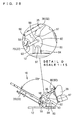
- FIGS. 20 to 24 show an embodiment wherein another different guide rail 60 is used.
- the guide face 62 has a recessed circular-arc form 64 centered about the pivot 95 for the third link 57, whereby the seat 30 can be held at rest (at a constant angle of 11 degree with the floor) until the backrest 20 is reclined from the raised position to 120 degree.
- the seat 30 thereafter rises and moves up to the highest level through 30 degree in FIG. 22 .
- the seat then lowers to form an increased angle with the backrest 20.
- the guide face 62 extends forward substantially horizontally as indicated at 67.
- the third link 57 rotates in the reclining direction, pulling the raised front end of the seat 30 down, whereby the backrest 20 and the seat 30 are brought to a nearly flat state as shown in FIG. 24 (at 160 degree as illustrated).
- varying relaxing angles can be realized merely by modifying the form of the guide face 62.
- the roller 72 serves as a pivot 74 for the joint portion 70, whereas the pivot 74 can be made movable on the guide face 62, with the roller 73 dispensed with.
- This embodiment uses a cam 80 for giving an adjustable relaxing angle.
- the drive source 42 is not shown, whereas an actuator or the like is provided for reclining the backrest 20 as in Embodiment 1. Cushions are not shown.
- the cam 80 is pivoted at an eccentric position to a support bracket 84 projecting from the base 12 to provide a reclining mechanism 40.
- the cam 80 is coupled to the backrest 20 by a second link 55.
- the cam 80 has an approximately elliptical cam face 82 on its outer periphery.
- the support bracket 84 and the second link 55 are pivoted respectively as at 97 and 98 to the cam at different positions on the major axis of the cam face 82.
- a roller 87 is supported by a bracket 35 projecting from the bottom wall of the seat 30 so as to be in bearing contact with the cam face 82.
- the roller 97 rolls along the cam face 82.
- modifications of the form of the cam face 82 provide varying relaxing angles.
- the backrest 20 is reclined by the drive source 42, and this movement is delivered through the link assembly 50, guide rail 60 or cam 80 to pivotally move the seat 30, whereas an actuator serving as the drive source 42 may be interposed between the base 12 and the third link 57 in Embodiments 3 to 5 so as to move the third link 57 about the pivot 95.
- the cam 80 may be made rotatable by a drive source.
- the present invention provide useful chair-type massage machines comprising a backrest and a seat which can be reclined by a single drive source while permitting the user to hold a relaxed posture.
Abstract
Description
- The present invention relates to massage machines of the chair type having a backrest and a seat which can be reclined. More particularly, the invention relates to chair-type massage machines comprising a backrest and a seat which can be reclined by a single drive source while permitting the person to be treated to hold a relaxed posture.
- Chair-type massage machines are known in which a backrest and a seat have massage means and can be reclined. For example,
JP2003-289975A - The provision of the independent drive sources for the respective backrest and seat makes the reclining mechanism large-sized and complex to consequently make the chair-type massage machine greater in size and complex in the mode of control.
Furthermore, the reclining mechanism comprising a plurality of drive sources encounters difficulty in positioning the backrest and the seat at a target angle in synchronism due, for example, to anomalies in the individual drive sources and variations in the load to be applied to the respective drive sources. The massage machine will then involve such an unnatural movement that one of the backrest and seat reaches the target angle with a delay after the other component has reached the target angle. - An object of the present invention is to provide a chair-type massage machine comprising a backrest and a seat which can be reclined by a single drive source while permitting the user to hold a relaxed posture.
- To fulfill the foregoing object, the present invention provides a chair-type massage machine comprising a backrest for the back of the user to bear on, a seat for the user to sit in, and a reclining mechanism for pivotally moving the backrest and the seat.
The reclining mechanism comprises a single drive source, and the drive source is coupled to the backrest and the seat by a link assembly.
The link assembly is operable to pivotally move the backrest from a raised position to a reclined position via an intermediate position by operating the drive source, the seat being tiltable to raise a front end thereof when the backrest is pivotally moved from the raised position to the intermediate position, the seat being tiltable to lower the raised lower end thereof when the backrest is pivotally moved from the intermediate position to the reclined position.
By virtue of this construction, the backrest and the seat can be reclined while permitting the user to hold a relaxed posture. - The present invention also provides a chair-type massage machine comprising a backrest for the back of the user to bear on, a seat for the user to sit in, and a reclining mechanism for pivotally moving the backrest and the seat.
The reclining mechanism comprises a single drive source, the drive source being coupled to one of the backrest and the seat, the backrest or the seat having the drive source coupled thereto being pivotally movably supported.
The backrest is connected to the seat by a link assembly having a joint portion, which is movable along a guide rail.
The drive source is operable to move the joint portion of the link assembly along the guide rail, as coupled to the pivotal movement of the backrest or the seat, and to pivotally move the backrest from a raised position to a reclined position via an intermediate position, the guide rail having a curved guide face for tilting the seat to raise a front end thereof when the backrest is pivotally moved from the raised position to the intermediate position and for tilting the seat to lower the raised front end thereof when the backrest is pivotally moved from the intermediate position to the reclined position.
By virtue of this construction, the backrest and the seat can be reclined while permitting the user to hold a relaxed posture. - The present invention further provides a chair-type massage machine wherein a base is provided with a backrest for the back of the user to bear on, a seat for the user to sit in, and a reclining mechanism for pivotally moving the backrest and the seat.
The reclining mechanism comprises a single drive source, which is coupled to one of the backrest and the seat. The backrest or the seat having the drive source coupled thereto is pivotally movably supported.
A link is pivoted at one end thereof to the backrest or the seat having the drive source coupled thereto, the link having the other end pivoted to a cam member supported by the base, the cam member being provided at a portion thereof with a cam face in bearing contact with the backrest or the seat not coupled to the drive source,
The drive source is operable to cause the link to rotate the cam member and to pivotally move the backrest from a raised position to a reclined position via an intermediate position, the cam face being so shaped as to tilt the seat to raise a front end thereof when the backrest is pivotally moved from the raised position to the intermediate position and as to tilt the seat to lower the raised front end thereof when the backrest is pivotally moved from the intermediate position to the reclined position.
By virtue of this construction, the backrest and the seat can be reclined while permitting the user to hold a relaxed posture. - In any one of the forgoing chair-type massage machines, a single drive source is provided for the reclining mechanism, which is therefore unlikely to become large-sized or complex. Furthermore, the use of the link assembly or the like assures a stabilized reclining movement free of variations.
-
-
FIG. 1 is shows a chair-type massage machine of first embodiment of the invention in a raised position; -
FIG. 2 is shows the chair-type massage machine of the first embodiment of the invention in an intermediate position; -
FIG. 3 is shows the chair-type massage machine of the first embodiment of the invention as reclined; -
FIG. 4 is a view showing a chair-type massage machine in a reclined position and having a link assembly of different embodiment; -
FIG. 5 is a view showing a chair-type massage machine in a reclined position and having a link assembly of another different embodiment; -
FIG. 6 includes a side elevation of a chair-type massage machine of second embodiment of the invention and an enlarged fragmentary view; -
FIG. 7 includes a side elevation of the chair-type massage machine of the second embodiment of the invention and an enlarged fragmentary view; -
FIG. 8 includes a side elevation of the chair-type massage machine of the second embodiment of the invention and an enlarged fragmentary view; -
FIG. 9 includes a side elevation of the chair-type massage machine of second embodiment of the invention and an enlarged fragmentary view; -
FIG. 10 includes a side elevation of a chair-type massage machine of third embodiment of the invention and an enlarged fragmentary view; -
FIG. 11 includes a side elevation of the chair-type massage machine of the third embodiment of the invention and an enlarged fragmentary view; -
FIG. 12 includes a side elevation of the chair-type massage machine of the third embodiment of the invention and an enlarged fragmentary view; -
FIG. 13 includes a side elevation of the chair-type massage machine of the third embodiment of the invention and an enlarged fragmentary view; -
FIG. 14 includes a side elevation of the chair-type massage machine of the third embodiment of the invention and an enlarged fragmentary view; -
FIG. 15 includes a side elevation of a chair-type massage machine of fourth embodiment of the invention and an enlarged fragmentary view; -
FIG. 16 includes a side elevation of the chair-type massage machine of the fourth embodiment of the invention and an enlarged fragmentary view; -
FIG. 17 includes a side elevation of the chair-type massage machine of the fourth embodiment of the invention and an enlarged fragmentary view; -
FIG. 18 includes a side elevation of the chair-type massage machine of the fourth embodiment of the invention and an enlarged fragmentary view; -
FIG. 19 includes a side elevation of the chair-type massage machine of the fourth embodiment of the invention and an enlarged fragmentary view; -
FIG. 20 includes a side elevation of a chair-type massage machine of fifth embodiment of the invention and an enlarged fragmentary view; -
FIG. 21 includes a side elevation of the chair-type massage machine of the fifth embodiment of the invention and an enlarged fragmentary view; -
FIG. 22 includes a side elevation of the chair-type massage machine of the fifth embodiment of the invention and an enlarged fragmentary view; -
FIG. 23 includes a side elevation of the chair-type massage machine of the fifth embodiment of the invention and an enlarged fragmentary view; -
FIG. 24 includes a side elevation of the chair-type massage machine of the fifth embodiment of the invention and an enlarged fragmentary view; -
FIG. 25 includes a side elevation of a chair-type massage machine of sixth embodiment of the invention and an enlarged fragmentary view; -
FIG. 26 includes a side elevation of the chair-type massage machine of the sixth embodiment of the invention and an enlarged fragmentary view; -
FIG. 27 includes a side elevation of the chair-type massage machine of the sixth embodiment of the invention and an enlarged fragmentary view; -
FIG. 28 includes a side elevation of the chair-type massage machine of the sixth embodiment of the invention and an enlarged fragmentary view; and -
FIG. 29 includes a side elevation of the chair-type massage machine of the sixth embodiment of the invention and an enlarged fragmentary view; - The present invention provides chair-
type massage machines 10, which will be descried below with reference to the drawings.
First, the overall construction of the chair-type massage machine 10 will be described generally. As shown inFIG. 1 , themassage machine 10 has abase 12 to be placed on the floor. Usingpivots 90, thebase 12 has supported thereon aseat 30 for the user to sit in and abackrest 20 for the back of the user to bear on. The seat and the backrest are pivotally movable by the recliningmechanism 40 to be described below.
Thebackrest 20 comprises abackrest frame 22 and acushion 23 or the like provided around theframe 22 and is provided in its interior with massage means 24 movable upward and downward by alift unit 25 for massaging the shoulders, back, waist, etc. of the user.
Theseat 30 comprises acushion 33 or the like provided around aseat frame 32 and is provided in its interior with an air bag or like massage means (not shown) as required. Aleg portion 38 for placing thereon the legs of the user can be provided at the front end of theseat 30. Theleg portion 38 shown inFIG. 1 is made integral with theseat 30, whereas theleg portion 38 may be adapted to accommodate therein the calves and the feet for a massage unit (not shown) to give a massage to the calves as shown inFIG. 6 or the like to be described later. Theleg portion 38 may be made pivotally movable relative to theseat 30. - The
reclining mechanism 40 comprises adrive source 42 and alink assembly 50. Thereclining mechanism 40 of the present invention is characterized in that both thebackrest 20 and theseat 30 can be reclined by thesingle drive source 42. Furthermore, thebackrest 20 and theseat 30 can be reclined while permitting the user to hold a relaxed posture. - The expression that the user as positioned in a relaxed posture refers to such a state of the user that he or she is not particularly burdened on his body, or is not locally subjected to a force, or will not assume any objectionable posture when the
backrest 20 is reclined with the user seated in theseat 30 with his back bearing on thebackrest 20.
If thebackrest 20 only is merely reclined without tilting theseat 30, an objectionable force is likely to act on the abdominal muscle or waist to reduce the massage effect. - According to the present invention, therefore, the
backrest 20 and theseat 30 can be reclined so as to retain the following "relax angle" in accordance with the reclining angle of thebackrest 20, so that the machine can be reclined while permitting the user to hold a relaxed state. - First, when the
backrest 20 is in a raised position (hereinafter referred to as the "raised position"), theseat 30 is so tilted that the front end of theseat 30 is positioned at a slightly higher level above the floor than the rear end thereof. This enables the user to seat deep in theseat 30 and feel relaxed. - As the
backrest 20 is inclined backward from this raised position, theseat 30 is tilted with its front end moved up. This enables the user to follow the reclining movement of thebackrest 20 and feel at ease without applying any force to the abdominal muscle. When thebackrest 20 is reclined to an intermediate value of the greatest reclining angle (hereinafter referred to as an "intermediate position"), theseat 30 is inclined greatest with its front end raised to the highest level. - When the
backrest 20 is reclined further from the intermediate position, theseat 30 is inclined with its front end moved down, and theseat 30 returns to the same angle as in the raised position upon thebackrest 20 reaching the greatest reclining angle (hereinafter referred to as a "reclined position"), whereby thebackrest 20 and theseat 30 are brought to a nearly flat state. After thebackrest 20 has moved past the intermediate position, the back of the body of the user is held fully in intimate contact with thebackrest 20, with the center of gravity shifted toward thebackrest 20. Accordingly, even if theseat 30 resumes such an angle that it is positioned nearly in parallel with the floor, thebackrest 20 and theseat 30 can be brought to the flat state while permitting the user to remain relaxed with no objectionable force acting on the body of the user. Such angles enabling the user to feel relaxed will be referred to as "relaxing angles." - Since the user can be held in a relaxed posture free of any unnatural force acting on his body by adjusting the angle of inclination of the
seat 30 in accordance with the reclining angle of thebackrest 20, the massage operation to be subsequently performed can produce the greatest possible effect. Thebackrest 20 and theseat 30 can be returned from the flat state to the raised position through a movement reverse to the foregoing movement while permitting the user to remain relaxed, with the result that the massage effect given will not be nullified or diminished. - For example,
FIG. 1 shows a single actuator serving as thesingle drive source 42 for thereclining mechanism 40. The actuator has one end connected to the upper end of a fixedframe 51 extending forwardly upward approximately from the center of thebase 12. The other end of the actuator is connected to the lower end of thebackrest 20.
The contraction of the actuator in the chair-type massage machine 10 pulls the lower end of thebackrest 20 as supported by thepivots 90, whereby thebackrest 20 itself is reclined as shown, for example, inFIGS. 2 and3 . - The
link assembly 50 can be composed of a plurality oflinks FIG. 1 , thelink assembly 50 comprises afirst link 53 pivoted as at 91 approximately to the center of thebase 12, asecond link 55 pivoted to a portion of thefirst link 53 close to the free end thereof and to the lower end of thebackrest 20, respectively, as at 92, 93 for interconnecting thelink 53 and thebackrest 20, and athird link 57 pivoted to the free end extremity of thefirst link 53 and to abracket 35 projecting from the bottom of theseat 30, respectively, as at 94, 95 for interconnecting thelink 53 and thebracket 35.
The present embodiment reclines with thebackrest 20 and theseat 30 held at a relaxing angle, and theseat 30 is held approximately at the same level in the raised position ofFIG. 1 and in the reclined position ofFIG. 3 . For this reason, thefirst link 53 and thethird link 57 move symmetrically about a vertical line inFIG. 1 andFIG. 3 . The stroke length of thesecond link 55 operatively connected to thebackrest 20 is so determined as to effect this movement. If the actuator serving as thedrive source 42 has a sufficiently large stroke length, thepivot 92 between thesecond link 55 and thefirst link 53 can be positioned closer to thepivot 94 connecting thethird link 57 to thefirst link 53, such that in an extreme case, pivots 92, 94 can be a common pivot.
Furthermore, the highest level of the front end of theseat 30 is adjustable by shifting the position of thepivot 95 for connecting thethird link 57 to theseat 30. (As thepivot 95 is positioned closer to thepivot 90, the level can be higher.) - With the
reclining mechanism 40 of the foregoing construction, thedrive source 42 is operated, starting to recline thebackrest 20 from the raised position ofFIG. 1 , whereby thesecond link 55 is pushed forward, and thefirst link 53 inclines forward about the pivotedpoint 91 on the base 12 to push out thethird link 57 forward. This pivotally moves theseat 30, moving the front end thereof upward about thepivot 90.
When thebackrest 20 reclines from the raised position to an intermediate position (an approximately intermediate position between the raised position ofFIG. 1 and the reclined position ofFIG. 3 ) as shown inFIG. 2 , thelink assembly 50 becomes so shaped that thefirst link 53 and thethird link 57 are arranged along a straight line, bringing the front end of theseat 30 to the highest level.
Accordingly, if thedrive source 42 is further operated, thebackrest 20 reclines from the intermediate position ofFIG. 2 , thesecond link 55 is pushed forward, and thefirst link 53 further inclines forward about the pivotedpoint 91 on thebase 12. This reclines thethird link 57, pulling down the raised front end of theseat 30 and consequently bringing thebackrest 20 and theseat 30 to a flat state as shown inFIG. 3 . - Thus, the
backrest 20 is reclined by operating thedrive source 42, whereby theseat 30 is also tilted, with thebackrest 20 and theseat 30 held at a relaxing angle, so that the user as seated in theseat 30 can be moved to a lying position without permitting any disagreeable force acting on the body of the user.
With thebackrest 20 and theseat 30 positioned flat, various modes of massage can be given by the massage means to massage the body effectively. - The
backrest 20 and theseat 30 can be operated in a manner reverse to the above by operating the drive source in a direction opposite to the above, i.e., by extending the actuator in the illustrated embodiment, whereby the machine can be returned to the raised position while holding the relaxing angle. - The
backrest 20 and theseat 30 can be inclined at different relaxing angles by varying the length of thelinks link assembly 50 and shafting the position of the pivoted points 91, 92, 93, 94, 95. - Although the drive source 42 (actuator) is used for reclining the
backrest 20 according to the foregoing description, an actuator may be provided between thefirst link 53 and the base 12 as shown inFIG. 4 to move thefirst link 53 about thepivot 91. Alternatively, an actuator may be provided between thepivot 94 for connecting thefirst link 53 to thethird link 57 and the base 12 as shown inFIG. 5 for moving thefirst link 53 about thepivot 91. -
FIGS. 6 to 9 show another chair-type massage machine 10 wherein areclining mechanism 40 comprises alink assembly 50. A further detailed description is given of the relaxing angle between thebackrest 20 and theseat 30. For a better understanding, thedrive source 42 is not shown, whereas an actuator or the like is provided for reclining thebackrest 20. Furthermore, cushions are not shown. - With reference to
FIG. 6 , thebackrest 20 and theseat 30 are held at a relaxing angle, for example, of 109 degree when the chair-type massage machine 10 is in a raised position. As thebackrest 20 is reclined to an intermediate position in this state as shown inFIGS. 7 and8 , theseat 30 is so tilted as to raise its front end. This decreases the angle between thebackrest 20 and theseat 30 to 106 degree inFIG. 7 , shifting the center of gravity of the user toward thebackrest 20. Accordingly no objectionable force will act on the body of the user when thebackrest 20 is reclined. When thefirst link 53 of thelink assembly 50 is nearly aligned with thethird link 57 thereof as seen inFIG. 8 , theseat 30 has its front end raised to the highest level. When thebackrest 20 is further reclined, thethird link 57 is reclined about thepivot 94, pulling down theseat 30 as shown inFIG. 9 . Thus, thebackrest 20 and theseat 30 can be moved to a nearly flat state (thebackrest 20 and theseat 30 shown are at a relaxing angle of 160 degree). - With Embodiments 1 and 2, the
reclining mechanism 40 comprises alink assembly 50 for reclining thebackrest 20 and theseat 30, whereas according to the present embodiment, thefirst link 53 is replaced by aguide rail 60 for realizing the same operation as above. Although thedrive source 42 is not shown for a better understanding, an actuator or the like is provided for reclining thebackrest 20 as in Embodiment 1. Furthermore, cushions and the like are not shown. - The same
second link 55 andthird link 57 of Embodiments 1 and 2 are connected together by apivot 74, which has aroller 72. Theroller 72 is supported by a flexiblejoint portion 70 and is movable on aguide rail 60 provided on thebase 12. Preferably, theroller 72 and theguide rail 60 are so designed that one of them is shaped to have a recess, i.e., a groove, and the other thereof has a projection fittable in the groove. - Each of the
second link 55 and thethird link 57 has a length, which can be determined suitably, for example, in accordance with the position of theguide rail 60 and the level of the front end of theseat 30.
Theroller 72 provided on thejoint portion 70 can be prepared from a resin. - The
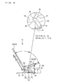
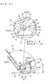
guide rail 60 has acurved guide face 62 for contact with theroller 72 so as to recline thebackrest 20 and theseat 30 having the relaxing angle therebetween. - With reference to Detail Drawing A of
FIG. 10 , theguide face 62 has a forwardly upward slope so as to make theseat 30 pivotally movable with its front end moving upward during the movement from a raised position to an intermediate position. When thebackrest 20 is reclined from the raised position, theroller 72 is pushed by thesecond link 55 to move forwardly upward along theguide face 62, causing thethird link 57 to push the front portion of theseat 30 upward as shown inFIGS. 11 and12 .
The curve of theguide face 62 has a recessed circular-arc form 64 which is centered about thepivot 90 serving as the center of pivotal movement of theseat 30 and thebackrest 20. Thebackrest 20 and theseat 30, while holding a relaxing angle of 106 degree therebetween, can therefore recline until theseat 30 inclines through about 30 degree with respect to a horizontal plane. This is suitable in the case where the user reads books with thebackrest 20 reclined at a desired angle. - With reference to
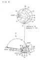
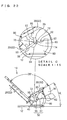
FIG. 13 , the guide face 62 changes from the recessed circular-arc form 64 to a projecting circular-arc form 65 at a position where thebackrest 20 and theseat 30 reach the vicinity of the intermediate position. As theguide face 62 extends forward, the guide face has adownward slope 66. When thebackrest 20 is further reclined from the intermediate position, theseat 30 having its front end raised is pulled down by the reclining of thethird link 57, with the result that thebackrest 20 and theseat 30 can be moved until they assume a flat state as seen inFIG. 14 . - Thus, with the use of the
guide rail 60, the relaxing angle between thebackrest 20 and theseat 30 is made adjustable so that the user can hold a relaxed posture. The form of theguide face 62 need not be limited to that of the present embodiment. The guide face can be so shaped as in Embodiment 4 given below, or can be modified suitably in accordance with the desired relaxing angle. -
FIGS. 15 to 19 show another embodiment comprising aguide rail 60 which is different from the one included in Embodiment 3. This embodiment is the same as Embodiment 3 with the exception of the form of theguide face 62. - This embodiment is so designed that the relaxing angle increases as the
backrest 20 is reclined by a recessed circular-arc form 64 when the machine is brought from the raised position to the intermediate position. Stated more specifically, the relaxing angle is 106 degree in the raised position as shown inFIG. 15 . The angle increases to 109 degree, 111 degree or 120 degree as shown inFIGS. 16 to 18 . Accordingly, the body of the user as seated in theseat 30 can be reclined in a natural state, with his waist stretched gradually. - After the intermediate position shown in
FIG. 18 has been reached, theguide face 62 extends forward substantially horizontally as indicated at 67. This causes thethird link 57 to rotate in the reclining direction, pulling the raised front end of theseat 30 down, whereby thebackrest 20 and theseat 30 are brought to a nearly flat state as shown inFIG. 19 (at 160 degree as illustrated). -
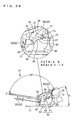
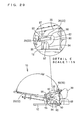
FIGS. 20 to 24 show an embodiment wherein anotherdifferent guide rail 60 is used. - With this embodiment, the
guide face 62 has a recessed circular-arc form 64 centered about thepivot 95 for thethird link 57, whereby theseat 30 can be held at rest (at a constant angle of 11 degree with the floor) until thebackrest 20 is reclined from the raised position to 120 degree. Theseat 30 thereafter rises and moves up to the highest level through 30 degree inFIG. 22 . The seat then lowers to form an increased angle with thebackrest 20. - After the intermediate position shown in
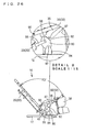
FIG. 22 has been reached, theguide face 62 extends forward substantially horizontally as indicated at 67. Thethird link 57 rotates in the reclining direction, pulling the raised front end of theseat 30 down, whereby thebackrest 20 and theseat 30 are brought to a nearly flat state as shown inFIG. 24 (at 160 degree as illustrated).
Thus, varying relaxing angles can be realized merely by modifying the form of theguide face 62. - According to Embodiments 3 to 5, the
roller 72 serves as apivot 74 for thejoint portion 70, whereas thepivot 74 can be made movable on theguide face 62, with the roller 73 dispensed with. - This embodiment uses a
cam 80 for giving an adjustable relaxing angle. For a better understanding, thedrive source 42 is not shown, whereas an actuator or the like is provided for reclining thebackrest 20 as in Embodiment 1. Cushions are not shown. - The
cam 80 is pivoted at an eccentric position to asupport bracket 84 projecting from the base 12 to provide areclining mechanism 40. Thecam 80 is coupled to thebackrest 20 by asecond link 55.
For example as shown inFIG. 25 , thecam 80 has an approximatelyelliptical cam face 82 on its outer periphery. Thesupport bracket 84 and thesecond link 55 are pivoted respectively as at 97 and 98 to the cam at different positions on the major axis of thecam face 82. - A
roller 87 is supported by abracket 35 projecting from the bottom wall of theseat 30 so as to be in bearing contact with thecam face 82. Theroller 97 rolls along thecam face 82. - When the
backrest 20 is reclined from the raised position (FIG. 25 ) in the chair-type massage machine 10 of the above construction, thesecond link 55 is pushed out forward, rotating thecam 80 clockwise inFIG. 25 . Since thecam 80 is generally elliptical, theroller 87 in bearing contact with thecam face 82 moves upward along thecam face 82, moving the front end of theseat 30 upward. While the relaxing angle was 109 degree relative to thebackrest 20 in the raised position, theseat 30 consequently inclines with increases in the relaxing angle to 113 degree, 116 degree, and 120 degree with an approach to the intermediate position as shown inFIGS. 26 to 28 , - When the
backrest 20 is brought to the intermediate position, theroller 87 reaches the top of thecam face 82 on the major axis, moving the front end of theseat 30 to the highest level.
Thebackrest 20 further reclines from this state, rotating thecam 82 to cause theroller 87 to move over the top of thecam face 82 on the major axis. This brings the raised front end of theseat 30 into a downward movement, and when thebackrest 20 reclines most greatly, thebackrest 20 and theseat 30 are brought to a flat state (at 160 degree as illustrated)as shown inFIG. 29 . - According to the present embodiment, modifications of the form of the
cam face 82 provide varying relaxing angles. - According to Embodiments 3 to 6, the
backrest 20 is reclined by thedrive source 42, and this movement is delivered through thelink assembly 50,guide rail 60 orcam 80 to pivotally move theseat 30, whereas an actuator serving as thedrive source 42 may be interposed between the base 12 and thethird link 57 in Embodiments 3 to 5 so as to move thethird link 57 about thepivot 95. In Embodiment 6, thecam 80 may be made rotatable by a drive source. - The present invention provide useful chair-type massage machines comprising a backrest and a seat which can be reclined by a single drive source while permitting the user to hold a relaxed posture.
- Apparently the present invention can be altered or modified by one skilled in the art without departing from the spirit of the invention. Such modifications are included within the scope of the invention as defined in the appended claims.
Claims (3)
- A chair-type massage machine comprising a backrest (20) for the back of the user to bear on, a seat (30) for the user to sit in, and a reclining mechanism (40) for pivotally moving the backrest (20) and the seat (30), the massage machine being characterized in that:the reclining mechanism (40) comprises a single drive source (42), the drive source (42) being coupled to the backrest (20) and the seat (30) by a link assembly (50),the link assembly (50) being operable to pivotally move the backrest (20) from a raised position to a reclined position via an intermediate position by operating the drive source (42), the seat (30) being tiltable to raise a front end thereof when the backrest (20)is pivotally moved from the raised position to the intermediate position, the seat (30) being tiltable to lower the raised front end thereof when the backrest (20) is pivotally moved from the intermediate position to the reclined position.
- A chair-type massage machine comprising a backrest (20) for the back of the user to bear on, a seat (30) for the user to sit in, and a reclining mechanism (40) for pivotally moving the backrest (20) and the seat (30), the massage machine being characterized in that:the reclining mechanism (40) comprises a single drive source (42), the drive source (42) being coupled to one of the backrest (20) and the seat (30), the backrest (20) or the seat (30) having the drive source (42) coupled thereto being pivotally movably supported,the backrest (20) being connected to the seat (30) by a link assembly (50) having a joint portion (70), the joint portion (70) of the link assembly being movable along a guide rail (60),the drive source (42) being operable to move the joint portion (70) of the link assembly (50) along the guide rail (60), as coupled to the pivotal movement of the backrest (20) or the seat (30), and to pivotally move the backrest (20) from a raised position to a reclined position via an intermediate position, the guide rail (60) having a curved guide face (62) for tilting the seat (30) to raise a front end thereof when the backrest (20) is pivotally moved from the raised position to the intermediate position and for tilting the seat (30) to lower the raised front end thereof when the backrest (20) is pivotally moved from the intermediate position to the reclined position.
- A chair-type massage machine wherein a base (12) is provided with a backrest (20) for the back of the user to bear on, a seat (30) for the user to sit in, and a reclining mechanism (40) for pivotally moving the backrest (20) and the seat (30), the massage machine being characterized in that:the reclining mechanism (40) comprises a single drive source (42), the drive source (42) being coupled to one of the backrest (20) and the seat (30), the backrest (20) or the seat (30) having the drive source (42) coupled thereto being pivotally movably supported,a link (55) being pivoted at one end thereof to the backrest (20) or the seat (30) having the drive source (42) coupled thereto, the link (55) having the other end pivoted to a cam member (80) supported by the base (12), the cam member (80) being provided at a portion thereof with a cam face (82) in bearing contact with the backrest (20) or the seat (30) not coupled to the drive source,the drive source (42) being operable to cause the link (55) to rotate the cam member (80) and to pivotally move the backrest (20) from a raised position to a reclined position via an intermediate position, the cam face (82) being so shaped as to tilt the seat (30) to raise a front end thereof when the backrest (20) is pivotally moved from the raised position to the intermediate position and as to tilt the seat (30) to lower the raised front end thereof when the backrest (20) is pivotally moved from the intermediate position to the reclined position.
Applications Claiming Priority (1)
| Application Number | Priority Date | Filing Date | Title |
|---|---|---|---|
| JP2007187887A JP4435215B2 (en) | 2007-07-19 | 2007-07-19 | Chair type massage machine |
Publications (2)
| Publication Number | Publication Date |
|---|---|
| EP2016866A1 true EP2016866A1 (en) | 2009-01-21 |
| EP2016866B1 EP2016866B1 (en) | 2010-09-15 |
Family
ID=39790114
Family Applications (1)
| Application Number | Title | Priority Date | Filing Date |
|---|---|---|---|
| EP08012969A Expired - Fee Related EP2016866B1 (en) | 2007-07-19 | 2008-07-17 | Chair-type massage machine |
Country Status (6)
| Country | Link |
|---|---|
| US (2) | US20090021063A1 (en) |
| EP (1) | EP2016866B1 (en) |
| JP (1) | JP4435215B2 (en) |
| CN (1) | CN101347381B (en) |
| DE (1) | DE602008002488D1 (en) |
| TW (1) | TW200916085A (en) |
Families Citing this family (18)
| Publication number | Priority date | Publication date | Assignee | Title |
|---|---|---|---|---|
| JP5433832B2 (en) * | 2008-11-25 | 2014-03-05 | 有限会社ビューティフルライフ | Chair |
| JP5274325B2 (en) * | 2009-03-23 | 2013-08-28 | 三洋電機株式会社 | Massage machine |
| JP5350961B2 (en) * | 2009-09-30 | 2013-11-27 | ファミリーイナダ株式会社 | Chair type massage machine |
| SG2014005904A (en) * | 2011-02-18 | 2014-03-28 | Daito Electric Machine Ind | Chair-type massage apparatus |
| CN102293704B (en) * | 2011-07-11 | 2013-03-20 | 宁波康福特健身器械有限公司 | Chair type massager |
| CN102415933B (en) * | 2011-08-29 | 2013-06-05 | 宁波康福特健身器械有限公司 | Massage chair capable of simulating zero gravity state |
| CN102375882B (en) * | 2011-09-19 | 2014-10-15 | 奇智软件(北京)有限公司 | Method, device and browser for rapidly accessing webpage |
| CN103536082A (en) * | 2012-07-16 | 2014-01-29 | 王万强 | Body building chair |
| CN103230172B (en) * | 2013-04-27 | 2015-07-29 | 常州工学院 | Multi-function ofice chair |
| CN105581541B (en) * | 2014-10-20 | 2018-10-02 | 乔山健身器材(上海)有限公司 | With the electrically propelled chair for facing upward function of lying |
| JP6436387B2 (en) * | 2014-12-26 | 2018-12-12 | 株式会社フジ医療器 | Chair massage machine |
| JP6632812B2 (en) * | 2015-04-28 | 2020-01-22 | 株式会社フジ医療器 | Chair type massage machine |
| FR3066896B1 (en) * | 2017-06-05 | 2021-01-29 | Etablissements Lebrun | ARTICULATED SEAT SYSTEM. |
| CN108670783B (en) * | 2018-05-17 | 2019-11-26 | 王文霞 | A kind of comfort type medical treatment and nursing back hammers chair |
| JP6624752B1 (en) | 2018-11-02 | 2019-12-25 | 忠寛 奥平 | Examination table |
| WO2022015095A1 (en) * | 2020-07-17 | 2022-01-20 | 주식회사 바디프랜드 | Reclining chair |
| TWI768520B (en) * | 2020-10-28 | 2022-06-21 | 名一生物科技股份有限公司 | Wheel chair |
| CN113509361B (en) * | 2021-06-03 | 2022-06-28 | 吉林大学 | Multifunctional massage equipment for patient nursing |
Citations (5)
| Publication number | Priority date | Publication date | Assignee | Title |
|---|---|---|---|---|
| EP0361302A2 (en) | 1988-09-28 | 1990-04-04 | WHITESUN S.p.A. | Tanning chair |
| DE19926011A1 (en) * | 1999-06-08 | 2000-12-14 | Fuji Iryoki Osaka Kk | Armchair massaging device has reclinable back and footrest which can be raised and lowered which are connected so that backrest can be inclined when footrest is raised |
| US6390546B1 (en) * | 2000-07-06 | 2002-05-21 | Liao Tsung Ming | Massaging chair |
| US6974186B1 (en) | 2004-07-03 | 2005-12-13 | Horng Jiun Chang | Chair |
| US20070120408A1 (en) * | 2005-11-29 | 2007-05-31 | Kuang Yu Metal Working Co., Ltd. | Backrest and armrest synchronous adjustment device for a massage chair |
Family Cites Families (15)
| Publication number | Priority date | Publication date | Assignee | Title |
|---|---|---|---|---|
| US1028548A (en) * | 1911-12-01 | 1912-06-04 | Martin L Cromer | Adjustable-chair. |
| US2016133A (en) * | 1932-01-11 | 1935-10-01 | Heywood Wakefield Co | Reclining chair |
| JPS5229554B2 (en) * | 1973-04-17 | 1977-08-02 | ||
| US3934929A (en) * | 1974-09-03 | 1976-01-27 | Sybron Corporation | Adjustable dental chair |
| US4492407A (en) * | 1982-07-19 | 1985-01-08 | Syntex (U.S.A.) Inc. | Patient support and transverse motion linkage therefor |
| CH668541A5 (en) * | 1986-01-07 | 1989-01-13 | Provenda Marketing Ag | WORK CHAIR, ESPECIALLY FOR USE AS OFFICE CHAIR. |
| CN2145545Y (en) * | 1993-01-01 | 1993-11-10 | 丁建新 | Multifunctional chair |
| CA2122294A1 (en) * | 1994-04-27 | 1995-10-28 | Peter C. Boetzkes | Dental patient's chair |
| US5826940A (en) * | 1995-11-27 | 1998-10-27 | Hodgdon; Dewey | Reactive multi-position chair |
| GB9918263D0 (en) * | 1999-08-04 | 1999-10-06 | Britax Rumbold Ltd | Seating unit of a passenger vehicle |
| EP1116652B1 (en) * | 2000-01-14 | 2006-03-15 | Be Aerospace, Inc. | Passenger seat with variable length seat bottom |
| DE10019484A1 (en) * | 2000-04-19 | 2001-10-31 | Recaro Aircraft Seating Gmbh | Vehicle seat, in particular passenger seat |
| US6439636B1 (en) * | 2001-02-07 | 2002-08-27 | Ming C. Kuo | Vehicle electric reclining seats |
| DE102005016943B4 (en) * | 2005-04-12 | 2006-11-30 | Stanzwerk Wetter Sichelschmidt Gmbh & Co. Kg | Ottoman |
| JP4715636B2 (en) * | 2006-05-26 | 2011-07-06 | パナソニック電工株式会社 | Chair massage machine |
-
2007
- 2007-07-19 JP JP2007187887A patent/JP4435215B2/en active Active
-
2008
- 2008-06-17 TW TW097122510A patent/TW200916085A/en unknown
- 2008-07-15 CN CN2008101360954A patent/CN101347381B/en active Active
- 2008-07-16 US US12/173,987 patent/US20090021063A1/en not_active Abandoned
- 2008-07-17 DE DE602008002488T patent/DE602008002488D1/en active Active
- 2008-07-17 EP EP08012969A patent/EP2016866B1/en not_active Expired - Fee Related
-
2011
- 2011-03-08 US US13/042,639 patent/US20110156458A1/en not_active Abandoned
Patent Citations (5)
| Publication number | Priority date | Publication date | Assignee | Title |
|---|---|---|---|---|
| EP0361302A2 (en) | 1988-09-28 | 1990-04-04 | WHITESUN S.p.A. | Tanning chair |
| DE19926011A1 (en) * | 1999-06-08 | 2000-12-14 | Fuji Iryoki Osaka Kk | Armchair massaging device has reclinable back and footrest which can be raised and lowered which are connected so that backrest can be inclined when footrest is raised |
| US6390546B1 (en) * | 2000-07-06 | 2002-05-21 | Liao Tsung Ming | Massaging chair |
| US6974186B1 (en) | 2004-07-03 | 2005-12-13 | Horng Jiun Chang | Chair |
| US20070120408A1 (en) * | 2005-11-29 | 2007-05-31 | Kuang Yu Metal Working Co., Ltd. | Backrest and armrest synchronous adjustment device for a massage chair |
Also Published As
| Publication number | Publication date |
|---|---|
| US20110156458A1 (en) | 2011-06-30 |
| JP2009022485A (en) | 2009-02-05 |
| CN101347381A (en) | 2009-01-21 |
| CN101347381B (en) | 2011-08-31 |
| JP4435215B2 (en) | 2010-03-17 |
| US20090021063A1 (en) | 2009-01-22 |
| EP2016866B1 (en) | 2010-09-15 |
| DE602008002488D1 (en) | 2010-10-28 |
| TW200916085A (en) | 2009-04-16 |
Similar Documents
| Publication | Publication Date | Title |
|---|---|---|
| EP2016866B1 (en) | Chair-type massage machine | |
| TWI484950B (en) | Chair-type massage apparatus | |
| JP5654871B2 (en) | Chairs, especially dentist chairs with seats with tiltable legrests | |
| US20030006639A1 (en) | Legrest-carrying chair | |
| US20080129099A1 (en) | Seat reclining mechanism for power wheelchair | |
| JP2014042812A (en) | Chair type massage machine | |
| JP4037674B2 (en) | Chair | |
| JP5733889B2 (en) | Chair type massage machine | |
| JP2000107241A (en) | Chair for drip and artificial dialysis | |
| CN108835989B (en) | Sofa chair capable of lying flat | |
| CN108523495B (en) | Multi-pose adjusting seat | |
| JP2005218511A (en) | Chair | |
| JP6302180B2 (en) | Chair massage machine | |
| CN108294515A (en) | A kind of seat of double acting power drive | |
| JP2006095144A (en) | Chair, wheelchair and massage seat | |
| JP4843809B2 (en) | IV chair | |
| JP2009153744A (en) | Chair type massage machine | |
| JP2001299499A (en) | Backrest structure of chair | |
| WO2014006768A1 (en) | Chair-type massage machine | |
| JP2002078743A (en) | Standing up motion supporting device | |
| JP2018047298A (en) | Chair type massage machine | |
| JPS6223479Y2 (en) | ||
| JP2004016370A (en) | Bed for nursing care | |
| TWI548372B (en) | An electric chair with a supine function | |
| WO2015166690A1 (en) | Chair type massage machine |
Legal Events
| Date | Code | Title | Description |
|---|---|---|---|
| PUAI | Public reference made under article 153(3) epc to a published international application that has entered the european phase |
Free format text: ORIGINAL CODE: 0009012 |
|
| AK | Designated contracting states |
Kind code of ref document: A1 Designated state(s): AT BE BG CH CY CZ DE DK EE ES FI FR GB GR HR HU IE IS IT LI LT LU LV MC MT NL NO PL PT RO SE SI SK TR |
|
| AX | Request for extension of the european patent |
Extension state: AL BA MK RS |
|
| 17P | Request for examination filed |
Effective date: 20090716 |
|
| 17Q | First examination report despatched |
Effective date: 20090818 |
|
| AKX | Designation fees paid |
Designated state(s): DE ES FR GB IT |
|
| GRAP | Despatch of communication of intention to grant a patent |
Free format text: ORIGINAL CODE: EPIDOSNIGR1 |
|
| GRAS | Grant fee paid |
Free format text: ORIGINAL CODE: EPIDOSNIGR3 |
|
| GRAA | (expected) grant |
Free format text: ORIGINAL CODE: 0009210 |
|
| AK | Designated contracting states |
Kind code of ref document: B1 Designated state(s): DE ES FR GB IT |
|
| REG | Reference to a national code |
Ref country code: GB Ref legal event code: FG4D |
|
| REF | Corresponds to: |
Ref document number: 602008002488 Country of ref document: DE Date of ref document: 20101028 Kind code of ref document: P |
|
| PG25 | Lapsed in a contracting state [announced via postgrant information from national office to epo] |
Ref country code: IT Free format text: LAPSE BECAUSE OF FAILURE TO SUBMIT A TRANSLATION OF THE DESCRIPTION OR TO PAY THE FEE WITHIN THE PRESCRIBED TIME-LIMIT Effective date: 20100915 |
|
| PG25 | Lapsed in a contracting state [announced via postgrant information from national office to epo] |
Ref country code: ES Free format text: LAPSE BECAUSE OF FAILURE TO SUBMIT A TRANSLATION OF THE DESCRIPTION OR TO PAY THE FEE WITHIN THE PRESCRIBED TIME-LIMIT Effective date: 20101226 |
|
| PLBE | No opposition filed within time limit |
Free format text: ORIGINAL CODE: 0009261 |
|
| STAA | Information on the status of an ep patent application or granted ep patent |
Free format text: STATUS: NO OPPOSITION FILED WITHIN TIME LIMIT |
|
| 26N | No opposition filed |
Effective date: 20110616 |
|
| REG | Reference to a national code |
Ref country code: DE Ref legal event code: R097 Ref document number: 602008002488 Country of ref document: DE Effective date: 20110616 |
|
| PGFP | Annual fee paid to national office [announced via postgrant information from national office to epo] |
Ref country code: FR Payment date: 20130724 Year of fee payment: 6 Ref country code: GB Payment date: 20130717 Year of fee payment: 6 |
|
| GBPC | Gb: european patent ceased through non-payment of renewal fee |
Effective date: 20140717 |
|
| REG | Reference to a national code |
Ref country code: FR Ref legal event code: ST Effective date: 20150331 |
|
| PG25 | Lapsed in a contracting state [announced via postgrant information from national office to epo] |
Ref country code: GB Free format text: LAPSE BECAUSE OF NON-PAYMENT OF DUE FEES Effective date: 20140717 Ref country code: FR Free format text: LAPSE BECAUSE OF NON-PAYMENT OF DUE FEES Effective date: 20140731 |
|
| PGFP | Annual fee paid to national office [announced via postgrant information from national office to epo] |
Ref country code: DE Payment date: 20200304 Year of fee payment: 13 |
|
| REG | Reference to a national code |
Ref country code: DE Ref legal event code: R119 Ref document number: 602008002488 Country of ref document: DE |
|
| PG25 | Lapsed in a contracting state [announced via postgrant information from national office to epo] |
Ref country code: DE Free format text: LAPSE BECAUSE OF NON-PAYMENT OF DUE FEES Effective date: 20220201 |