JP4037674B2 - Chair - Google Patents
Chair Download PDFInfo
- Publication number
- JP4037674B2 JP4037674B2 JP2002098411A JP2002098411A JP4037674B2 JP 4037674 B2 JP4037674 B2 JP 4037674B2 JP 2002098411 A JP2002098411 A JP 2002098411A JP 2002098411 A JP2002098411 A JP 2002098411A JP 4037674 B2 JP4037674 B2 JP 4037674B2
- Authority
- JP
- Japan
- Prior art keywords
- seat
- backrest
- footrest
- posture
- chair
- Prior art date
- Legal status (The legal status is an assumption and is not a legal conclusion. Google has not performed a legal analysis and makes no representation as to the accuracy of the status listed.)
- Expired - Fee Related
Links
Images


Description
【0001】
【発明の属する技術分野】
本発明は、座部の前・後端部に足載部と背もたれ部をそれぞれ連設した椅子に関するものである。
【0002】
【従来の技術】
従来、図6に示すように、座部100と背もたれ部200とを備え、同背もたれ部200をリクライニング可能とした椅子Xはよく知られている。
【0003】
また、図示するように、前記座部100の前端部に足載部300を連設し、同足載部300の座部に対する取付角度が可変となるように、変動可能とした構造についても、例えば椅子型のマッサージ機や理美容と特殊椅子などにおいてよく知られている。
【0004】
さらに、座部100の後部を前部に比べて下げた構造のものもあり、かかる構造では、腰掛けたときにゆったりとしたリラックス感が味わえる。
【0005】
しかも、図6(b)に示すように足載部300を上方へ回動した場合、腰掛けている使用者の大腿部や脚部が臀部に比べて上方に位置するので、疲労回復に効果があるとされ、そのような姿勢をとって休息をとる者も多い。
【0006】
【発明が解決しようとする課題】
ところが、上記した従来の構成の椅子は、足載部300の動きが独立した単独の出没動作となるために、例えば背もたれ部200が垂直に近い状態で足載部300が出ると背中が立った状態のまま足を伸ばす姿勢となるため、身体が窮屈感を受ける。
【0007】
上記身体の窮屈感を解消するために、足載部300と背もたれ部200とが連動する椅子も存在するが、これは背もたれ部200の傾動により使用者の腰と背もたれ部200の相対位置がずれてしまうので、使用者は腰を動かして着座姿勢を整えねばならなかった。これは、特に背もたれ部200にマッサージ機能を付加したものでは、肩位置のずれが起こるので着座姿勢のずれは大きな問題となる。しかも、その際に足載部200が出ている状態であれば、使用者の足が宙に浮いた状態となるので着座姿勢を整えることが難しい。特に、足載部が使用者の両足を包み込むように凹部形状となっているものでは不便さが顕著になっていた。
【0008】
また、上述の図6(a)のように、上記身体の窮屈感を解消するために予め座面を前高に形成すれば、足載部が出た状態でも身体が窮屈にならないようにすることも可能だが、この場合、常に座面が前高になっている為、このままの姿勢から立ち上がろうとした場合、立ち上がりにくい欠点がある。
【0009】
本発明は、上記課題を解決することのできる椅子を提供することを目的としている。
【0010】
【課題を解決するための手段】
(1)請求項1記載の本発明では、座部の前・後端部に足載部と背もたれ部をそれぞれ連設し、前記背もたれ部をリクライニング自在に構成するとともに、前記座部を、水平面に対する傾斜角度が変化するように可動とし、前記足載部の前記座部に対する上下方向への回動動作に連動して前記座部を変動可能とした椅子であって、前記足載部、座部、及び背もたれ部の保持姿勢を変更可能な姿勢変位機構と、この姿勢変位機構を制御する制御部と、を備え、前記制御部は、前記足載部が上方回動する場合、座部を前高後低方向に変動させる一方、足載部が下方回動する場合は、座部を前低後高方向に変動させ、しかも、前記座部が前高後低方向に変動する際には、前記背もたれ部と前記座部との間の角度αを維持したまま一体的に後方へ変動するように制御することとした。
【0011】
(2)請求項2記載の本発明では、請求項1記載の椅子において、操作によって前記制御部を介して前記姿勢変更機構を駆動させることのできる操作パネルを備え、前記制御部は、前記座部が前高後低方向に変動する際に、前記背もたれ部と前記座部との間の角度αを維持するように制御した後、前記操作パネルの操作によって前記姿勢変更機構を制御して、使用者を仰向け状態となるように前記背もたれ部のみを更に所定角度βだけ単独にリクライニング可能とした。
【0012】
(3)請求項3記載の本発明では、施療子を備えるマッサージユニットを具備し、マッサージ機能を有することとした。
【0015】
【発明の実施の形態】
本実施形態に係る椅子は、座部の前・後端部に足載部と背もたれ部をそれぞれ連設し、前記背もたれ部をリクライニング自在に構成するとともに、前記座部を、水平面に対する傾斜角度が変化するように可動とし、前記足載部の前記座部に対する上下方向への回動動作に連動して前記座部を変動可能とした椅子であって、前記足載部、座部、及び背もたれ部の保持姿勢を変更可能な姿勢変位機構と、この姿勢変位機構を制御する制御部と、を備え、前記制御部は、前記制御部は、前記足載部が上方回動する場合、座部を前高後低方向に変動させる一方、足載部が下方回動する場合は、座部を前低後高方向に変動させ、しかも、前記座部が前高後低方向に変動する際には、前記背もたれ部と前記座部との間の角度αを維持したまま一体的に後方へ変動するように制御するようにしたものである。
【0016】
足載部が座部に対して上下方向へ回動するという動作は、足載部の好ましくは上側近傍に設けられた枢軸を中心に回動する動作、さらには軸回動以外の出没動作により上側に出る動作をも含む概念であり、使用者が座部を動かして、同座部の水平面に対する傾斜角度を変更した際に、足載部も前記座部の動きに連動して上下方向に変動するようにして、いちいち足載部を個別に動かす必要をなくしている。
【0017】
また、前記足載部が上方回動する場合、座部が前高後低方向に変動する一方、足載部が下方回動する場合は、座部が前低後高方向に変動するように構成することが好ましい。
【0018】
例えば足載部が座部との間をなす角度が拡開する方向へ回動した場合(上方回動)、座部は背もたれ部に対して座部と背もたれ部との間をなす角度が縮閉する方向に変動するように(前高後低方向)、また、足載部が座部との間をなす角度が縮閉する方向へ回動した場合(下方回動)、座部は背もたれ部との間をなす角度が拡開する方向に変動する(前低後高方向)ように構成することが望ましい。
【0019】
かかる構成とすることにより、例えば通常の基本姿勢を、使用者が座部に腰掛けたり座部から立ち上がったりすることが容易な姿勢とすると、足載部を上方回動すれば座部が前高後低方向に変動するので、大腿部、脚部が臀部よりも上方に位置することになって血流が良くなり疲労回復に効果のある楽な姿勢をとれる一方、足載部を下方回動して前記基本姿勢に近づけると、座部が前低後高方向に変動して大腿部、脚部が臀部よりも下方に位置することになるのでそのまま立ち上がることも容易となる。
【0020】
特に、前記座部が前高後低方向に変動する際に、背もたれ部は前記座部との相対角度を維持するようにするとよい。
【0021】
すなわち、使用者が腰深く腰掛けた状態となるように座部が動いいた場合、座部と背もたれ部とが相対角度を維持したままなので、使用者は窮屈感がなく、なおかつ身体のずれも生じることがなくなる。これは、たとえば後述するように、椅子にマッサージ機能を付加した場合、特に背もたれ部にマッサージ手段を設けた場合などは、肩位置がずれないので着座姿勢を前述のように変更しても心地よいマッサージが行える。
【0022】
また、背もたれ部をリクライニング自在に構成し、座部の前高後低方向への変動に連動して、背もたれ部は後方へリクライニング動作し、座部の前低後高方向への変動に連動して、背もたれ部は前方へリクライニング動作するように構成している。
【0023】
この場合、座部を大きく前高後低方向に変動させると、この動きに連動して背もたれ部が後方へリクライニグ動作し、さらに、座部が前高後低方向に変動するということは、足載部は上方回動することになる。したがって、使用者は足を上に上げて寝た状態となって疲労回復に都合の良い姿勢でリラックスすることができる。
【0024】
ところで、上述してきた構成の椅子は、椅子型マッサージ機の椅子として好適に用いることができる。
【0025】
すなわち、例えば前記背もたれ部に施療子を備えるマッサージユニットを配設し、マッサージ機能を備えるようにするものである。
【0026】
かかる椅子をマッサージ機として使用することにより、足の血流が良好でマッサージ効果をより向上させることができる。また、本実施形態の椅子であれば、前述したように、座部を動かしても肩位置がずれないので背もたれ部にマッサージユニットを設けるのに好適となる。なお、マッサージ機能は背もたれ部以外の他の個所に設けることもできることは当然である。
【0027】
【実施例】
以下、本発明の実施例を図面を参照しながら説明する。なお、本実施例では本発明に係る椅子をマッサージ機能を有するマッサージ椅子Aとして説明する。
【0028】
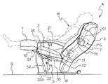
図1は本実施例に係るマッサージ椅子Aの側面視による説明図であり、図示する状態を本マッサージ椅子Aの基本姿勢とする。
【0029】
マッサージ椅子Aは、図示するように、座部2の前・後端部に足載部1と背もたれ部3をそれぞれ連設した構成であり、座部2の下部には同座部2を支持する基台部4を設けている。21は座部2の両側に設けた肘掛、41は基台部4の下部に設けた脚座である。
【0030】
そして、基台部4内において、前記座部2の裏面から下方向けて支持アーム22を突設し、同支持アーム22の先端部に設けた座部用枢支部22aを中心に前後方向へ動かすことができるようにしている。すなわち、水平面に対する傾斜角度が変化するように前記座部2を可動とするものであり、座部2は前高後低方向あるいは前低後高方向にその姿勢を変動することができる。
【0031】
かかる座部2に連設された前記足載部1及び背もたれ部3については、それぞれ水平面(椅子設置面G)に対する角度が可変となるように動かすことが可能となっている。すなわち、背もたれ部3は所謂リクライニング自在に構成されている。
【0032】
かかる動きを実現するために、本実施例では、前記基台部4内に足載部1、座部2、背もたれ部3の保持姿勢を変更可能な姿勢変位機構5を配設し、図示しない操作パネルの操作によって同姿勢変位機構5をこれも図示しない制御部を介して駆動して、足載部1、座部2、背もたれ部3を所望する姿勢に動かせるようにしている。
【0033】
姿勢変位機構5は、図示するように、座部2と脚座41との間を座部用アクチュエータ52により連結するとともに、前記支持アーム22の中央近傍には、先端を足載部1に連結した足載部用アクチュエータ51と、先端を背もたれ部3に連結した背もたれ部用アクチュエータ53の各基端部を枢着している。10は足載部用アクチュエータ51の先端部と足載部1との連結部、24は座部用アクチュエータ52と座部2との枢支連結部、31は背もたれ部3と座部2との枢支連結部、32は背もたれ部用アクチュエータ53の先端部と背もたれ部3との連結部、54は両アクチュエータ51,53の共通枢支部である。
【0034】
各アクチュエータ51,52,53は空気圧や油圧によるシリンダ機構、あるいはモータとラックアンドピ二オンなどからなる機構など適宜採用することができる。
【0035】
また、背もたれ部3には、主なるマッサージ動作を実行するマッサージユニット6を図示しない昇降用モータにより上下昇降自在に設けるとともに、これも図示しないが複数のエアセルを配設し、エアの給排により膨縮してエアマッサージを行えるようにしている。61はマッサージユニット6の昇降を案内するガイドレールである。なお、前記エアセルは、背もたれ部3のほか、前記足載部1や座部2に設けることもできる。
【0036】
マッサージユニット6内には、使用者Mに直接当接して多彩なマッサージ動作を行う揉み玉駆動ユニット7を収納配設しており、同揉み玉駆動ユニット7は、左右一対の施療子である揉み玉71,71を図示しない叩きモータにより前後方向に揺動させることによって行う叩き機能と、前記揉み玉71,71をこれも図示しない揉み用モータによって偏心回動させることによって行う揉み機能とを実行可能としている。しかも、同揉み玉駆動ユニット7は、同じく図示しない進退用モータにより、背もたれ部3の表側(使用者と接する側)に向けて進退移動可能に構成され、強力な指圧動作、複雑な3D揉み動作を実行可能としている。
【0037】
なお、かかるマッサージユニット6の昇降量、揉み玉駆動ユニット7の進退量及び揉み玉71,71の回動量は前記した操作パネルを介して制御可能としている。
【0038】
上記構成のマッサージ椅子Aにおいて、本発明の要旨となるのは、前記足載部1、座部2、及び背もたれ部3の保持姿勢を変更可能な姿勢変位機構5を制御する制御部を備え、前記制御部は、前記足載部が上方回動する場合、座部を前高後低方向に変動させる一方、足載部が下方回動する場合は、座部を前低後高方向に変動させ、しかも、前記座部が前高後低方向に変動する際には、前記背もたれ部と前記座部との間の角度αを維持したまま一体的に後方へ変動するように制御したことにある。
【0039】
本実施例では、前記した足載部用アクチュエータ51の先端部と足載部1との連結部10を枢支部として、この枢支部である連結部10を中心にして座部2を上下回動するように構成している。なお、枢支部を介して回動するものみならず上下方向へ出没自在とする構成とすることもできる。
【0040】
さらに、背もたれ部3に関しても、前述したようにリクライニング自在に構成するとともに、前記座部2の前高後低方向への変動に連動して、背もたれ部3が後方へリクライニング動作し、座部2の前低後高方向への変動に連動して、背もたれ部3が前方へリクライニング動作するように構成している。
【0041】
しかも、本実施例においては、前記座部2が前高後低方向に変動する際に、背もたれ部3は前記座部2との相対角度を維持するようにしている。
【0042】
ここで、図2を参照しながら本実施例に係るマッサージ椅子Aの動きについて説明する。
【0043】
図2は本実施例に係るマッサージ椅子Aの足載部1、座部2及び背もたれ部3の動きを示す説明図であり、図2(a)がマッサージ椅子Aの図1に示した基本姿勢と対応している。
【0044】
本実施例に係るマッサージ椅子Aは、前述したようにリクライニング自在であり、なおかつ座部2が前高後低方向に変動する際に、背もたれ部3は前記座部2との相対角度を維持するようにしている。
【0045】
上記マッサージ椅子Aにおいて、図2(b)に示すように、足載部1を座部2に対して連結部10を中心に上方回動すると(図2(b)の矢印f2)、座部2が連動して座部用枢支部22aを中心に前高後低方向へ回動する(図2(b)の矢印f1)。かかる図2(b)に対応するのが図3である。
【0046】
一方、背もたれ3についても座部2との相対角度を維持したまま一体的に動くので、図示するように、使用者Mは何ら窮屈感を受けることなく姿勢を後方傾斜するように変更することができる。
【0047】
すなわち、図3に示すように、この場合における背もたれ部用アクチュエータ53は固定状態であり(図1の状態と同じ)、座部用アクチュエータ52が伸延して、図2(b)に示すように、座部2と背もたれ部3との間の角度αを維持したまま座部2と背もたれ部3とが一体的に後方へ変動するのである。
【0048】
このように、足載部1を上方回動すると、背もたれ部3が自動的に後方へリクライニグすることになり、しかもこの背もたれ部3と座部2とは一体的に動くので、使用者Mは自然に腰深く腰掛けた状態となる。このように、本実施例においては、座部2の動きと背もたれ部3とが一体的に動くので、座部2を前高後低状態に動かす場合などは特にリクライニング機構はなくてもよいことになる。
【0049】
またこのときには、大腿部や脚部が臀部よりも自然に自動的に上方に位置することになるので、リラックスした姿勢で休みながら下肢の血流をよくして疲労回復を図ることができ、さらに、かかる状態でマッサージ機能をはたらかせることでマッサージ効果が著しく向上する。
【0050】
また、図2(b)に示した姿勢から、背もたれ部3のみを時計方向へ所定角度βだけ単独にリクライニングして、図2(c)に示すように、使用者Mが仰向け状態とすることもできる。
【0051】
かかる姿勢では、自然に足を上に上げて寝た状態となるので、疲労回復に都合の良い姿勢となりリラックスすることができ、さらにこの状態でマッサージを行えばマッサージ効果をより向上させることができる。
【0052】
この後、使用者Mが例えばこのマッサージ椅子Aから離れようとして、座部2を元の基本姿勢に戻すように操作パネルを操作して座部2を前低後高方向に変動すると、足載部1は下方回動して図1及び図2(a)に示した基本姿勢に復帰する。
【0053】
そして、図1及び図2(a)の状態からであれば、足載部1は邪魔になることがないので使用者Mは難なく立ち上がることができる。
【0054】
(他の実施例)
また、他の実施例として、マッサージ椅子Aは図2(d)に示すような動作が行える。この図2(d)に対応するのが図4である。
【0055】
すなわち、図4に示すように、通常のリクライニング動作で背もたれ部3を大きく後方へ倒して、使用者Mが略仰向け状態となる場合の動作である。
【0056】
使用者Mが操作パネルを操作して、背もたれ用アクチュエータ53を収縮させて背もたれ部3を枢支連結部31を中心に回動させて後方へ倒し、図2(d)に示すように座部2との間の角度αが開くように大きくリクライニグ動作させた場合、同時に座部用アクチュエータ52が進出動作して座部用枢支部22aを中心に座部2を動かし、座部2が連動して前低後高方向へ変動する(図2(c)の矢印f1参照)。そして、上述してきたように、足載部1は相対的に座部2と連動しているので、同足載部1についても連動して連結部10を中心に上方回動する(図2(d)の矢印f2)。
【0057】
このように、使用者Mが仰向け姿勢をとるように背もたれ部3をリクライニング動作させると(図4)、先の実施例における図2(c)で示した状態と同様な姿勢、すなわち、使用者Mは自然に足を上に上げて寝た状態となるので、この場合においても疲労回復に都合の良い姿勢となってリラックスすることができ、さらにこの状態でマッサージを行えばマッサージ効果をより向上させることができる。
【0058】
ところで、上述してきた各実施例(図2(b)〜(d))においては、足載部1の基本回動量としては使用者Mの膝が若干屈曲する程度までに抑えているが、使用者Mの好みに応じて操作パネルを操作することで、例えば、図5に示すように、膝が略直線状に伸びる程度までを上限として回動させることができる。かかる位置を上限として、足載部1の基本回動量については適宜設定してよい。
【0059】
また、図2(c),(d)のいずれの姿勢からであっても、座部2を前低後高方向に動かせば、これに連動して足載部1は下方へ回動して図1及び図2(a)に示す状態となるので、使用者Mはマッサージ椅子Aからの立ち上がりなどに何ら支障をきたすことがない。
【0060】
以上、本発明に係る椅子を本実施例においてはマッサージ機能を有するマッサージ椅子Aとして説明したが、通常の椅子として例えばソファのような用い方をしてもよい。その場合、足載部の姿勢をいちいち手作業で変える必要のない、足載部を備える使い勝手の良好な椅子となる。
【0061】
あるいは理美容用椅子などの業務用の特殊な椅子として使用することもでき、下肢を臀部よりも上方に位置させたリラックス姿勢を自然にとれる椅子となり、使用者Mにとって座りごこちがよく疲労回復の図れる椅子として有用となる。
【0062】
また、上記してきた実施例においては、足載部1を使用者Mの足を包み込むような凹形状のものとしたが(図1、図3、図4、図5参照)、例えば上述の理美容椅子に設けられたもののように、フラットな板状のものであってもよい。
【0063】
【発明の効果】
本発明は、以上に説明したような形態で実施され、以下に記載されるような効果を奏する。
【0064】
(1)請求項1記載の本発明では、足載部を使用時に窮屈感がなく、座部を変動しても身体のずれが生じないので心地よく、しかも、足の血流が向上して疲労回復が図れる。また、足載部と座部との姿勢を、それぞれ個別に手作業で変える必要がなく、足載部を備える使い勝手の良好な椅子となる。また、椅子から離れるときなどに、座部を元に戻せば相対的に足載部も連動することになるので、立ち上がりが楽になる。また、例えば通常の基本姿勢を、使用者が座部に腰掛けたり座部から立ち上がったりすることが容易な姿勢とすると、足載部を上方回動すると、座部が前高後低方向に変動するので、大腿部、脚部が臀部よりも上方に位置して血流が良くなり疲労回復に効果のある楽な姿勢をとれる一方、足載部を下方回動すると、座部が前低後高方向に変動するので前記基本姿勢に近くなり、大腿部、脚部が臀部よりも下方に位置することになるのでそのまま立ち上がることも容易となる。
【0065】
(2)請求項2記載の本発明では、自然に足を上げて寝た状態とすること、疲労回復に都合の良い姿勢とすなりリラックスすることができる。
【0066】
(3)請求項3記載の本発明では、上記(1)、(2)の効果に加え、下肢の血流を良好にしてマッサージ効果をより向上させることができる。特に、背もたれ部にマッサージ機能を設けた場合で座部が前高後低方向に変動する際に、背もたれ部は前記座部との相対角度を維持する場合は、肩位置のずれがないのでマッサージ時に違和感などがなく快適なマッサージとなる。
【図面の簡単な説明】
【図1】本実施例に係るマッサージ椅子の側面視による説明図である。
【図2】同マッサージ椅子における座部、足載部及び背もたれ部の動きを示す説明図である。
【図3】リクライニング状態を側面視により示す説明図である。
【図4】座部と背もたれ部とが一体的にリクライニング動作した状態を側面視により示す説明図である。
【図5】足載部の回動限界を側面視により示す説明図である。
【図6】足載部を具備する従来の椅子の説明図である。
【符号の説明】
A マッサージ椅子
1 足載部
2 座部
3 背もたれ部
4 基台部
5 姿勢変位機構
10 連結部
31 枢支連結部[0001]
BACKGROUND OF THE INVENTION
The present invention relates to a chair in which a footrest portion and a backrest portion are connected to the front and rear end portions of a seat portion, respectively.
[0002]
[Prior art]
Conventionally, as shown in FIG. 6, a chair X that includes a
[0003]
Also, as shown in the figure, a structure in which a
[0004]
Furthermore, there is a structure in which the rear part of the
[0005]
In addition, as shown in FIG. 6 (b), when the
[0006]
[Problems to be solved by the invention]
However, since the chair having the conventional configuration described above is a single in / out operation in which the movement of the
[0007]
In order to eliminate the above-mentioned cramped feeling of the body, there is a chair in which the
[0008]
In addition, as shown in FIG. 6A described above, if the seating surface is formed in advance in order to eliminate the feeling of cramping of the body, the body will not be cramped even when the footrest portion is out. However, in this case, since the seating surface is always at the front height, there is a drawback that it is difficult to stand up when trying to stand up from this posture.
[0009]
An object of this invention is to provide the chair which can solve the said subject.
[0010]
[Means for Solving the Problems]
(1) In the present invention according to
[0011]
(2) In the present invention described in
[0012]
(3) In the present invention described in
[0015]
DETAILED DESCRIPTION OF THE INVENTION
The chair according to the present embodiment includes a footrest portion and a backrest portion connected to the front and rear end portions of the seat portion, respectively, and the backrest portion is configured to be reclining freely, and the seat portion has an inclination angle with respect to a horizontal plane. and I urchin movable to vary, a chair element which enables variation of the seat portion in interlock with the rotation of the vertical direction with respect to the seat portion of the footrest portion, the footrest portion, the seat portion, and A posture displacement mechanism capable of changing a holding posture of the backrest portion, and a control unit that controls the posture displacement mechanism, wherein the control unit is configured to be seated when the footrest portion rotates upward. When the foot part is rotated downward, the seat part is changed in the front low rear high direction, and the seat part is changed in the front high rear low direction. In the rear while maintaining the angle α between the backrest and the seat. It is obtained so as to control to vary.
[0016]
The movement of the footrest portion rotating in the vertical direction with respect to the seat portion is preferably an operation of pivoting around a pivot provided in the vicinity of the upper side of the footrest portion, and further by an appearance operation other than the pivoting motion. It is a concept that includes an upward movement, and when the user moves the seat and changes the inclination angle of the seat with respect to the horizontal plane, the footrest also moves in the vertical direction in conjunction with the movement of the seat. This eliminates the need to move the footrest individually.
[0017]
In addition, when the footrest portion is rotated upward, the seat portion is changed in the front-rear and lower direction, while when the footrest portion is rotated downward, the seat portion is changed in the front-rear and rear-high direction. It is preferable to configure.
[0018]
For example, when the angle between the footrest and the seat is rotated in the direction of widening (upward rotation), the angle between the seat and the backrest is reduced with respect to the backrest. The seat is backrested so that it changes in the closing direction (front high, low, low), and when the angle between the footrest and the seat rotates in the direction of closing (downward rotation) It is desirable to configure so that the angle between the two parts changes in the direction of expansion (front low, high rear).
[0019]
By adopting such a configuration, for example, if the normal basic posture is a posture in which the user can easily sit on the seat or stand up from the seat, the seat can be moved forward by rotating the footrest upward. Since the thigh and legs are positioned higher than the buttocks, the blood flow is improved and an easy posture that is effective for recovery from fatigue can be taken. When it moves close to the basic posture, the seat part changes in the front-rear and rear-high directions, and the thigh and legs are positioned below the buttocks, so that it is easy to stand up as it is.
[0020]
In particular, when the seat portion fluctuates in the front and rear and lower directions, the backrest portion may maintain a relative angle with the seat portion.
[0021]
That is, when the seat moves so that the user sits deeply, the seat and the backrest remain at a relative angle, so the user does not feel cramped and the body is displaced. Nothing will happen. For example, as will be described later, when a massage function is added to the chair, especially when a massage means is provided on the backrest portion, the shoulder position does not shift, so the comfortable posture can be changed even if the sitting posture is changed as described above. Can be done.
[0022]
Further, backrest portion reclines freely configure, in conjunction with the variation of the previous high after low direction of the seat portion, the backrest portion is reclined rearward, in conjunction with the variation in the height direction after the low front of the seat to, backrest it is configured to reclining movement forward.
[0023]
In this case, if the seat part is greatly changed in the front high and low direction, the backrest part will recline in conjunction with this movement, and the seat part will change in the front high and low direction. The mounting portion rotates upward. Therefore, the user can relax in a posture that is convenient for recovery from fatigue, with the feet raised to sleep.
[0024]
By the way, the chair of the structure mentioned above can be used suitably as a chair of a chair type massage machine.
[0025]
That is, for example, a massage unit including a treatment element is disposed on the backrest portion to provide a massage function.
[0026]
By using such a chair as a massage machine, the blood flow of the foot is good and the massage effect can be further improved. Moreover, if it is a chair of this embodiment, since a shoulder position does not shift | deviate even if it moves a seat part as mentioned above, it will become suitable for providing a massage unit in a backrest part. Of course, the massage function can be provided at a location other than the backrest.
[0027]
【Example】
Embodiments of the present invention will be described below with reference to the drawings. In the present embodiment, the chair according to the present invention will be described as a massage chair A having a massage function.
[0028]
FIG. 1 is an explanatory diagram of the massage chair A according to the present embodiment as viewed from the side, and the illustrated state is the basic posture of the massage chair A.
[0029]
As shown in the figure, the massage chair A has a structure in which a
[0030]
Then, in the
[0031]
The
[0032]
In order to realize such movement, in this embodiment, a
[0033]
As shown in the figure, the
[0034]
Each of the
[0035]
The
[0036]
In the
[0037]
In addition, the raising / lowering amount of the
[0038]
In the massage chair A configured as described above, the gist of the present invention includes a control unit that controls the
[0039]
In the present embodiment, the connecting
[0040]
Further, as described above, the
[0041]
Moreover, in the present embodiment, the
[0042]
Here, the movement of the massage chair A according to the present embodiment will be described with reference to FIG.
[0043]
FIG. 2 is an explanatory view showing the movement of the
[0044]
The massage chair A according to the present embodiment is reclining as described above, and the
[0045]
In the massage chair A, as shown in FIG. 2 (b), when the
[0046]
On the other hand, since the
[0047]
That is, as shown in FIG. 3, the
[0048]
Thus, when the
[0049]
Also, at this time, the thighs and legs are automatically positioned above the buttocks automatically, so you can improve your blood flow in the lower limbs while resting in a relaxed posture, and you can recover from fatigue. Furthermore, a massage effect improves remarkably by making a massage function work in this state.
[0050]
Further, from the posture shown in FIG. 2 (b), only the
[0051]
In such a posture, since it naturally goes to sleep with its feet raised, it can be relaxed with a posture that is convenient for recovery from fatigue, and if massage is performed in this state, the massage effect can be further improved. .
[0052]
Thereafter, going to leave the user M, for example, from the massage chair A, the variation before the high direction after low a
[0053]
And if it is from the state of FIG.1 and FIG.2 (a), since the
[0054]
(Other examples)
As another embodiment, the massage chair A can operate as shown in FIG. FIG. 4 corresponds to FIG. 2 (d).
[0055]
That is, as shown in FIG. 4, this is an operation in the case where the user M is in a substantially supine position by largely tilting the
[0056]
The user M operates the operation panel to contract the
[0057]
In this way, when the
[0058]
Incidentally, in each of the above-described embodiments (FIGS. 2B to 2D), the basic rotation amount of the
[0059]
Moreover, even if it is from any attitude | position of FIG.2 (c), (d), if the
[0060]
As mentioned above, although the chair concerning the present invention was explained as massage chair A which has a massage function in this example, it may be used like a sofa as a normal chair. In that case, it is a user-friendly chair having a footrest portion that does not require manual changes in the posture of the footrest portion.
[0061]
Or it can be used as a special chair for business use such as a barber / beauty chair, and it becomes a chair that can take a relaxed posture with the lower limbs positioned above the buttocks, so that the user M can sit comfortably and recover from fatigue. It becomes useful as a chair that can be planned.
[0062]
In the embodiment described above, the
[0063]
【The invention's effect】
The present invention is implemented in the form described above, and has the following effects.
[0064]
(1) In the present invention according to
[0065]
(2) In the present invention according to
[0066]
(3) In the present invention according to
[Brief description of the drawings]
FIG. 1 is an explanatory view of a massage chair according to an embodiment as viewed from the side.
FIG. 2 is an explanatory view showing movements of a seat part, a footrest part and a backrest part in the massage chair.
FIG. 3 is an explanatory diagram showing a reclining state in a side view.
FIG. 4 is an explanatory view showing a state in which the seat portion and the backrest portion are integrally reclined as viewed from the side.
FIG. 5 is an explanatory diagram showing a rotation limit of the footrest part in a side view.
FIG. 6 is an explanatory diagram of a conventional chair provided with a footrest portion.
[Explanation of symbols]
A
Claims (3)
前記足載部、座部、及び背もたれ部の保持姿勢を変更可能な姿勢変位機構と、
この姿勢変位機構を制御する制御部と、
を備え、
前記制御部は、
前記足載部が上方回動する場合、座部を前高後低方向に変動させる一方、足載部が下方回動する場合は、座部を前低後高方向に変動させ、しかも、前記座部が前高後低方向に変動する際には、前記背もたれ部と前記座部との間の角度αを維持したまま一体的に後方へ変動するように制御することを特徴とする椅子。 Respectively continuously arranged the footrest portion and the backrest portion in the front and rear ends of the seat, as well as constituting the backrest freely reclined, the seat, and by Uni movable to vary the inclination angle with respect to the horizontal plane, the a chair child which enables variation of the seat portion in interlock with the rotation of the vertical direction with respect to the seat portion of the footrest portion,
A posture displacement mechanism capable of changing a holding posture of the footrest portion, the seat portion, and the backrest portion;
A control unit for controlling the posture displacement mechanism;
With
The controller is
When the footrest portion is rotated upward, the seat portion is changed in the front high and low direction, while when the footrest portion is rotated downward, the seat portion is changed in the front low and rear high direction, A chair that is controlled to integrally move backward while maintaining the angle α between the backrest portion and the seat portion when the seat portion changes in the low direction from front to back .
前記制御部は、
前記座部が前高後低方向に変動する際に、前記背もたれ部と前記座部との間の角度αを維持するように制御した後、前記操作パネルの操作によって前記姿勢変更機構を制御して、使用者を仰向け状態となるように前記背もたれ部のみを更に所定角度βだけ単独にリクライニング可能としたことを特徴とする請求項1記載の椅子。 An operation panel capable of driving the posture changing mechanism via the control unit by an operation;
The controller is
When the seat changes in the low direction from front to back, control is performed to maintain the angle α between the backrest and the seat, and then the posture changing mechanism is controlled by operating the operation panel. The chair according to claim 1 , wherein only the backrest portion can be further reclined by a predetermined angle β so that the user is in a supine state .
Priority Applications (1)
| Application Number | Priority Date | Filing Date | Title |
|---|---|---|---|
| JP2002098411A JP4037674B2 (en) | 2002-04-01 | 2002-04-01 | Chair |
Applications Claiming Priority (1)
| Application Number | Priority Date | Filing Date | Title |
|---|---|---|---|
| JP2002098411A JP4037674B2 (en) | 2002-04-01 | 2002-04-01 | Chair |
Publications (2)
| Publication Number | Publication Date |
|---|---|
| JP2003289975A JP2003289975A (en) | 2003-10-14 |
| JP4037674B2 true JP4037674B2 (en) | 2008-01-23 |
Family
ID=29240417
Family Applications (1)
| Application Number | Title | Priority Date | Filing Date |
|---|---|---|---|
| JP2002098411A Expired - Fee Related JP4037674B2 (en) | 2002-04-01 | 2002-04-01 | Chair |
Country Status (1)
| Country | Link |
|---|---|
| JP (1) | JP4037674B2 (en) |
Cited By (1)
| Publication number | Priority date | Publication date | Assignee | Title |
|---|---|---|---|---|
| WO2020013539A1 (en) * | 2018-07-09 | 2020-01-16 | 주식회사 바디프랜드 | Massage device having erectable structure |
Families Citing this family (13)
| Publication number | Priority date | Publication date | Assignee | Title |
|---|---|---|---|---|
| JP4506283B2 (en) * | 2004-05-26 | 2010-07-21 | パナソニック電工株式会社 | Massage chair |
| JP4731422B2 (en) * | 2006-08-01 | 2011-07-27 | 三洋電機株式会社 | Chair type massage machine |
| JP4731439B2 (en) * | 2006-09-29 | 2011-07-27 | 三洋電機株式会社 | Chair type massage machine |
| JP2008142103A (en) * | 2006-12-06 | 2008-06-26 | Isozaki Kenko Kikaku:Kk | Massage machine |
| JP4879824B2 (en) * | 2007-06-01 | 2012-02-22 | 九州日立マクセル株式会社 | Massage machine |
| JP5306848B2 (en) * | 2009-02-17 | 2013-10-02 | 冨士ファニチア株式会社 | Chair |
| JP5364623B2 (en) * | 2010-03-09 | 2013-12-11 | ファミリーイナダ株式会社 | Chair type massage machine |
| JP2014042812A (en) * | 2012-07-31 | 2014-03-13 | Daito Denki Kogyo Kk | Chair type massage machine |
| KR101496306B1 (en) * | 2013-05-21 | 2015-03-02 | 강원대학교산학협력단 | back rest reclining apparatus for water pressure massage machine |
| JP2013233463A (en) * | 2013-08-27 | 2013-11-21 | Family Inada Co Ltd | Chair-type massage machine |
| JP5895222B2 (en) * | 2013-12-18 | 2016-03-30 | パナソニックIpマネジメント株式会社 | Reclining chair and chair type massage machine provided with the same |
| KR102224574B1 (en) * | 2014-06-20 | 2021-03-10 | 코웨이 주식회사 | An ending process for massage chair |
| KR102418220B1 (en) * | 2022-01-25 | 2022-07-07 | (주)성우메디텍 | swivel massage chair with sofa |
-
2002
- 2002-04-01 JP JP2002098411A patent/JP4037674B2/en not_active Expired - Fee Related
Cited By (1)
| Publication number | Priority date | Publication date | Assignee | Title |
|---|---|---|---|---|
| WO2020013539A1 (en) * | 2018-07-09 | 2020-01-16 | 주식회사 바디프랜드 | Massage device having erectable structure |
Also Published As
| Publication number | Publication date |
|---|---|
| JP2003289975A (en) | 2003-10-14 |
Similar Documents
| Publication | Publication Date | Title |
|---|---|---|
| JP5289711B2 (en) | Massage chair | |
| US4386803A (en) | Motorized reclining chair | |
| JP4037674B2 (en) | Chair | |
| JP5329998B2 (en) | Massage machine | |
| KR101266497B1 (en) | Massage chair having variable seat | |
| JP5733889B2 (en) | Chair type massage machine | |
| WO2011036880A1 (en) | Massager | |
| JP2000107241A (en) | Chair for drip and artificial dialysis | |
| JP6014952B2 (en) | Head-back tilt mechanism of the medical chair | |
| JP2005218511A (en) | Chair | |
| JP4866720B2 (en) | Chair massage machine | |
| JP2006095144A (en) | Chair, wheelchair and massage seat | |
| JP4843809B2 (en) | IV chair | |
| JP6218001B2 (en) | Exercise assistance device | |
| JP2019141571A (en) | Chair type massage machine | |
| JP4143392B2 (en) | Chair type massage machine | |
| JP2003070859A (en) | Armchair type massaging machine with built-in vibrator | |
| KR200362249Y1 (en) | Multi-functional sofa | |
| JP2013066743A (en) | Relaxation device | |
| JP5838110B2 (en) | Massage machine | |
| CN114848418A (en) | Chair type massage machine | |
| JP3067630U (en) | Elevating type electric chair transmission | |
| WO2019159811A1 (en) | Chair-type massaging machine | |
| CN107921309B (en) | Exercise assisting device | |
| JP2022094397A (en) | Massage machine |
Legal Events
| Date | Code | Title | Description |
|---|---|---|---|
| RD04 | Notification of resignation of power of attorney |
Free format text: JAPANESE INTERMEDIATE CODE: A7424 Effective date: 20040826 |
|
| A621 | Written request for application examination |
Free format text: JAPANESE INTERMEDIATE CODE: A621 Effective date: 20050328 |
|
| A977 | Report on retrieval |
Free format text: JAPANESE INTERMEDIATE CODE: A971007 Effective date: 20070222 |
|
| A131 | Notification of reasons for refusal |
Free format text: JAPANESE INTERMEDIATE CODE: A131 Effective date: 20070227 |
|
| A521 | Written amendment |
Free format text: JAPANESE INTERMEDIATE CODE: A523 Effective date: 20070427 |
|
| A521 | Written amendment |
Free format text: JAPANESE INTERMEDIATE CODE: A523 Effective date: 20070427 |
|
| TRDD | Decision of grant or rejection written | ||
| A01 | Written decision to grant a patent or to grant a registration (utility model) |
Free format text: JAPANESE INTERMEDIATE CODE: A01 Effective date: 20071002 |
|
| A61 | First payment of annual fees (during grant procedure) |
Free format text: JAPANESE INTERMEDIATE CODE: A61 Effective date: 20071101 |
|
| R150 | Certificate of patent or registration of utility model |
Free format text: JAPANESE INTERMEDIATE CODE: R150 |
|
| FPAY | Renewal fee payment (event date is renewal date of database) |
Free format text: PAYMENT UNTIL: 20101109 Year of fee payment: 3 |
|
| FPAY | Renewal fee payment (event date is renewal date of database) |
Free format text: PAYMENT UNTIL: 20101109 Year of fee payment: 3 |
|
| FPAY | Renewal fee payment (event date is renewal date of database) |
Free format text: PAYMENT UNTIL: 20111109 Year of fee payment: 4 |
|
| FPAY | Renewal fee payment (event date is renewal date of database) |
Free format text: PAYMENT UNTIL: 20111109 Year of fee payment: 4 |
|
| FPAY | Renewal fee payment (event date is renewal date of database) |
Free format text: PAYMENT UNTIL: 20121109 Year of fee payment: 5 |
|
| FPAY | Renewal fee payment (event date is renewal date of database) |
Free format text: PAYMENT UNTIL: 20121109 Year of fee payment: 5 |
|
| S111 | Request for change of ownership or part of ownership |
Free format text: JAPANESE INTERMEDIATE CODE: R313111 |
|
| FPAY | Renewal fee payment (event date is renewal date of database) |
Free format text: PAYMENT UNTIL: 20121109 Year of fee payment: 5 |
|
| R350 | Written notification of registration of transfer |
Free format text: JAPANESE INTERMEDIATE CODE: R350 |
|
| FPAY | Renewal fee payment (event date is renewal date of database) |
Free format text: PAYMENT UNTIL: 20131109 Year of fee payment: 6 |
|
| FPAY | Renewal fee payment (event date is renewal date of database) |
Free format text: PAYMENT UNTIL: 20131109 Year of fee payment: 6 |
|
| R250 | Receipt of annual fees |
Free format text: JAPANESE INTERMEDIATE CODE: R250 |
|
| R250 | Receipt of annual fees |
Free format text: JAPANESE INTERMEDIATE CODE: R250 |
|
| R250 | Receipt of annual fees |
Free format text: JAPANESE INTERMEDIATE CODE: R250 |
|
| R250 | Receipt of annual fees |
Free format text: JAPANESE INTERMEDIATE CODE: R250 |
|
| LAPS | Cancellation because of no payment of annual fees |