JP5289711B2 - Massage chair - Google Patents
Massage chair Download PDFInfo
- Publication number
- JP5289711B2 JP5289711B2 JP2007013174A JP2007013174A JP5289711B2 JP 5289711 B2 JP5289711 B2 JP 5289711B2 JP 2007013174 A JP2007013174 A JP 2007013174A JP 2007013174 A JP2007013174 A JP 2007013174A JP 5289711 B2 JP5289711 B2 JP 5289711B2
- Authority
- JP
- Japan
- Prior art keywords
- arm
- backrest
- armrest
- movable armrest
- massage chair
- Prior art date
- Legal status (The legal status is an assumption and is not a legal conclusion. Google has not performed a legal analysis and makes no representation as to the accuracy of the status listed.)
- Active
Links
- 230000007246 mechanism Effects 0.000 claims description 158
- 230000033001 locomotion Effects 0.000 claims description 21
- 230000002265 prevention Effects 0.000 claims description 14
- 238000004898 kneading Methods 0.000 description 31
- 210000002414 leg Anatomy 0.000 description 9
- 238000010586 diagram Methods 0.000 description 6
- 238000005452 bending Methods 0.000 description 4
- 230000008602 contraction Effects 0.000 description 4
- 208000003251 Pruritus Diseases 0.000 description 3
- 230000005540 biological transmission Effects 0.000 description 3
- 210000000245 forearm Anatomy 0.000 description 3
- 230000001360 synchronised effect Effects 0.000 description 3
- 210000001217 buttock Anatomy 0.000 description 2
- 230000000694 effects Effects 0.000 description 2
- 230000007803 itching Effects 0.000 description 2
- 230000000630 rising effect Effects 0.000 description 2
- 210000000689 upper leg Anatomy 0.000 description 2
- 206010013647 Drowning Diseases 0.000 description 1
- 208000027418 Wounds and injury Diseases 0.000 description 1
- 239000012141 concentrate Substances 0.000 description 1
- 230000006378 damage Effects 0.000 description 1
- 238000006073 displacement reaction Methods 0.000 description 1
- 210000003414 extremity Anatomy 0.000 description 1
- 208000014674 injury Diseases 0.000 description 1
- 238000004519 manufacturing process Methods 0.000 description 1
- 230000000284 resting effect Effects 0.000 description 1
- 238000005096 rolling process Methods 0.000 description 1
- 230000008961 swelling Effects 0.000 description 1
Images


Landscapes
- Massaging Devices (AREA)
Description
本発明は、使用者の手部または腕部を載置して該手部または腕部に適度な施療を行い得るようにした肘掛部を椅子本体に設けたマッサージ椅子であって、詳しくは、該肘掛部に腕揉み機構を備えると共に、背凭れ部のリクライニング角度に応じた適正な位置で使用者の手部または腕部に対して施療を施すことが可能なマッサージ椅子に関するものである。 The present invention is a massage chair provided with an armrest on the chair body, on which the user's hand or arm can be placed so that appropriate treatment can be performed on the hand or arm. The present invention relates to a massage chair that is provided with an arm cramping mechanism in the armrest and capable of treating the user's hand or arm at an appropriate position according to the reclining angle of the backrest.
従来から、椅子に座した状態でマッサージ効果が得られるマッサージ椅子が知られている。この種のマッサージ椅子としては、椅子本体の背凭れ部に内蔵してあるマッサージ機構により使用者の背部に対して揉みや叩き等のマッサージを行うものが代表的であるが、近年はこのようなマッサージ椅子の左右に配した肘掛部において、使用者の手部または腕部をマッサージし得る腕揉み機構を備えたものが市場でもよく見られるようになった。 2. Description of the Related Art Conventionally, massage chairs that can obtain a massage effect while sitting on a chair are known. A typical example of this type of massage chair is one that massages the back of the user with a massage mechanism built into the backrest of the chair body, such as squeezing or hitting the user. In the armrests arranged on the left and right sides of the massage chair, those equipped with an arm massage mechanism capable of massaging the user's hand or arm have become common on the market.
例えば、椅子本体の左右の肘掛部に腕揉み機構を備えたマッサージ椅子としては、図31に示したようなマッサージ椅子(特許文献1)が開示されており、このマッサージ椅子は、肘幅方向一側に弧状形成された立上り壁211を設けた肘掛部21を両側に設けた椅子本体2の上面適所に人体手部を各々載脱自在で該人体手部に膨縮施療を付与し得る圧縮空気給排気手段(膨縮袋12と、各膨縮袋12・12に各々ホース13・13を介して連通される圧縮空気給排装置14)を配設しており、施療者が着座状態で人体手部を両肘掛部21・21上面に安定的に保持させて、人体手部及び腕部の上側面から効率良く空圧施療することができるよう構成したものである。
しかし、この種従来例のマッサージ椅子は、背凭れ部を後方へリクライニングさせる場合、肘掛部に載置していた手部または腕部を該肘掛部の後方へ移動せざるを得なくなるため、肘掛部に備えた腕揉み機構における施療適正位置から手部または腕部がずれてしまい、背凭れ部をリクライニングさせた椅子本体に仰臥した姿勢では、手部または腕部に対する適正な施療が行えないという問題があった。 However, in this type of conventional massage chair, when reclining the backrest part, the hand or arm part placed on the armrest part must be moved to the back of the armrest part. The hand or arm is displaced from the appropriate treatment position in the arm massage mechanism provided in the arm, and in a posture lying on the chair body with the backrest reclining, proper treatment for the hand or arm cannot be performed. There was a problem.
また、従来例のマッサージ椅子は、肘掛部の高さが背凭れ部のリクライニングに関係なく固定されたものであるため、手部または腕部を肘掛部に載置したまま背凭れ部をリクライニングさせると、仰臥した胴体に対して手部または腕部が高く上がってしまい、使用者は窮屈な姿勢で手部または腕部に対する施療を受けざるを得ず、該姿勢での施療では、かえって疲労感をもたらすという課題もあった。 Moreover, since the height of the armrest part is fixed regardless of the reclining of the backrest part, the massage chair of the conventional example reclines the backrest part with the hand part or the arm part placed on the armrest part. Then, the hand or arm rises high with respect to the torso, and the user is forced to receive treatment for the hand or arm in a cramped posture. There was also a problem of bringing about.
そこで本発明は、上記問題点を解消する為に成されたものであり、使用者が常時リラックスした状態で使用でき、しかも背凭れ部のリクライニング角度に応じた適正な位置で手部または腕部等の被施療部位に適格な施療を施すことができるようにしたマッサージ椅子を提供することを目的とするものである。 Therefore, the present invention has been made to solve the above-mentioned problems, and can be used in a state where the user is always relaxed, and the hand or arm at an appropriate position according to the reclining angle of the backrest. It is an object of the present invention to provide a massage chair that can perform appropriate treatment on a treatment site such as the above.
すなわち、本発明のマッサージ椅子は、座部の後部に起立状態から倒伏状態へ起倒自在に設けられた背凭れ部を配備すると共に、該座部の左右両側部には各々肘掛部を配設したマッサージ椅子であって、前記各肘掛部は、下部の起立壁と、該起立壁の上部位置に配備され、人体の手部または腕部を載置挿入し得る凹部が形成されていると共に該凹部内に手部または腕部を施療し得る膨縮袋が配設してある腕揉み機構を配備した可動肘掛部に分割されており、これら起立壁上前部と可動肘掛部下前部間にリンク部材を介設すると共に該可動肘掛部後部と背凭れ部側部を枢着して可動肘掛部を揺動可能にし、背凭れ部の起倒動作に従って両肘掛部の各可動肘掛部が追従し得るようにし、前記可動肘掛部の幅方向内側には、前記可動肘掛部と前記起立壁との間に存する空間を遮蔽することができる板状の形態の挟み込み防止部材を設け、前記可動肘掛部の前記起立壁に対する上下動作に関わらず、常時、前記挟み込み防止部材による遮蔽がなされ、人体の一部を挟み込む要因を除去することができるものとしている。
That is, the massage chair of the present invention is provided with a backrest portion provided at the rear portion of the seat portion so as to be able to rise and fall from a standing state to a lying state, and an armrest portion is provided on each of the left and right sides of the seat portion. a by massage chair, each armrest portion includes a lower portion of the upright wall, is deployed in the upper position of the standing upright wall, with the human hand or recess the arm portions can enter placed inserted is formed The arm is divided into movable armrests provided with an arm squeezing mechanism in which an inflatable / deflection bag capable of treating the hand or arm is disposed in the recess, and between the upper front part of the standing wall and the lower front part of the movable armrest part The movable armrest is pivotable by pivotally attaching the rear part of the movable armrest and the side of the backrest, and the movable armrests of both armrests are arranged according to the tilting operation of the backrest. The movable armrest portion and the raising armrest portion are arranged on the inner side in the width direction of the movable armrest portion. A plate-like form of catch prevention member that can shield the space existing between the walls provided, regardless of the vertical movement relative to the upright wall of the movable armrest portion always shielded by the catch prevention member is made, It is assumed that a factor that sandwiches a part of the human body can be removed .
また、本発明のマッサージ椅子は、前記可動肘掛部後部と背凭れ部側部との枢着位置は、背凭れ部のリクライニング回動軸よりも上位置である構成にしたものとしている。 In the massage chair of the present invention, the pivoting position between the movable armrest rear portion and the backrest side portion is a position above the reclining rotation axis of the backrest portion.
さらに、本発明のマッサージ椅子は、前記可動肘掛部の後部における背凭れ部側部との枢着位置に、可動肘掛部位置を前後に位置調節し得るスライド機構が設けてあるものとしている。 Furthermore, the massage chair of the present invention is provided with a slide mechanism capable of adjusting the position of the movable armrest portion back and forth at the pivot position with the backrest side portion at the rear portion of the movable armrest portion.
また、本発明のマッサージ椅子は、前記背凭れ部側部における可動肘掛部の後部との枢着位置に、可動肘掛部後部位置を上下に位置調節し得るスライド機構が設けてあるものとしている。 In the massage chair of the present invention, a slide mechanism capable of vertically adjusting the position of the rear portion of the movable armrest portion is provided at a pivot position with the rear portion of the movable armrest portion on the backrest side portion.
さらに、本発明のマッサージ椅子は、前記リンク部材又は前記スライド機構に、可動肘掛部の位置を固定し得るロック機構等の固定手段が設けてあるものとしている。 Furthermore, in the massage chair of the present invention, fixing means such as a lock mechanism that can fix the position of the movable armrest portion is provided on the link member or the slide mechanism.
さらにまた、本発明のマッサージ椅子は、人体の手部または腕部を載置し得る前記可動肘掛部の上面は、前記腕揉み機構の凹部底面を兼用するものであるものとしている。 Furthermore, in the massage chair of the present invention, the upper surface of the movable armrest portion on which the hand portion or arm portion of the human body can be placed also serves as the bottom surface of the concave portion of the arm massaging mechanism.
よって、本発明のマッサージ椅子は、座部の後部に起立状態から倒伏状態へ起倒自在に設けられた背凭れ部を配備すると共に、該座部の左右両側部には各々肘掛部を配設したマッサージ椅子における前記各肘掛部を、下部の起立壁と、該起立壁の上部位置に配備され、人体の手部または腕部を載置挿入し得る凹部が形成されていると共に該凹部内に手部または腕部を施療し得る膨縮袋が配設してある腕揉み機構を配備した可動肘掛部に分割されており、これら起立壁上前部と可動肘掛部下前部間にリンク部材を介設すると共に該可動肘掛部後部と背凭れ部側部を枢着して可動肘掛部を揺動可能にし、背凭れ部の起倒動作に従って両肘掛部の各可動肘掛部が追従し得るようにした構成にしてあるため、前記腕揉み機構は可動肘掛部と共に背凭れ部の起倒動作に追従して後方且つ下方に移動するので、従来のような背凭れ部の起倒動作による手部または腕部のずれが生ずることがなく、常時、背凭れ部の起倒動作に追従対応させた腕揉み機構における施療適正位置を確保することができ、また、倒伏状態の背凭れ部に仰臥した使用者の胴体に対しても、従来のような手部または腕部が高くなって使用者が窮屈な姿勢を強いられることもなく、手部または腕部を安定した適性位置を確保することができる。その結果、使用者は常時リラックスした状態の中で背凭れ部の起倒角度に応じた適正な位置で手部または腕部に対する心地良い施療に専念することができるものとなる。
Therefore, the massage chair of the present invention is provided with a backrest portion provided at the rear portion of the seat portion so as to be able to rise and fall from a standing state to a lying state, and an armrest portion is provided on each of the left and right sides of the seat portion. and each of said armrest in massage chair, and a lower upright wall, is deployed in the upper position of the standing upright wall, the recess with the human hand or recess the arm portions can enter placed inserted is formed It is divided into movable armrests that are provided with an arm squeezing mechanism in which an inflatable bag that can treat the hand part or arm part is disposed, and a link member is provided between the upper front part of the standing wall and the lower front part of the movable armrest part. The movable armrest part can be pivoted by pivotally attaching the rear part of the movable armrest part and the side part of the backrest part, and each movable armrest part of both armrest parts can follow according to the tilting operation of the backrest part. Because of this structure, the arm folding mechanism is backrest together with the movable armrest. Because it moves backward and downward following the tilting motion of the backrest, there is no displacement of the hand or arm due to the tilting motion of the backrest as in the past, and the backrest tilting motion is always performed It is possible to secure an appropriate treatment position in the arm-kneading mechanism adapted to follow, and the hand part or arm part as in the conventional case is also high against the user's torso lying on the lying backrest part Thus, the user or the arm can be secured in a suitable position without being forced to take a tight posture. As a result, the user can concentrate on comfortable treatment for the hand or arm at an appropriate position corresponding to the tilt angle of the backrest in a constantly relaxed state.
また、本発明のマッサージ椅子は、前記可動肘掛部後部と背凭れ部側部との枢着位置を背凭れ部のリクライニング回動軸とは別位置であり、リクライニング回動軸よりも上位置になるようにしてあるため、背凭れ部の起倒動作に影響することがなく肘掛部を構成する起立壁上部の可動肘掛部を揺動可能に取り付けでき、マッサージ椅子の組立て作業が容易にできるものとなる。 Further, in the massage chair of the present invention, the pivoting position of the movable armrest rear part and the backrest side part is a position different from the reclining rotation axis of the backrest part, and is located above the reclining rotation axis. Because it is designed to be able to oscillate the movable armrest on the upper part of the standing wall that constitutes the armrest without affecting the back and forth movement of the backrest, it can easily assemble the massage chair It becomes.
さらに、本発明のマッサージ椅子は、前記可動肘掛部の後部における背凭れ部側部との枢着位置に、可動肘掛部位置を前後に位置調節し得るスライド機構が設けてあるため、使用者の好みや要望する施療位置に応じて可動肘掛部位置を前後に移動させて、腕揉み機構が手部または腕部の被施療部対応位置になるように位置や角度を調節することができる。 Furthermore, the massage chair of the present invention is provided with a slide mechanism that can adjust the position of the movable armrest portion back and forth at the pivotal position with the backrest side portion in the rear portion of the movable armrest portion. The movable armrest position can be moved back and forth in accordance with the preference and desired treatment position, and the position and angle can be adjusted so that the arm massaging mechanism becomes the position corresponding to the treatment portion of the hand or arm.
また、本発明のマッサージ椅子は、前記背凭れ部側部における可動肘掛部の後部との枢着位置に、可動肘掛部後部位置を上下に位置調節し得るスライド機構が設けてあるものとしているため、背凭れ部が起立した状態の場合は、使用者の好みや要望する施療位置に応じて可動肘掛部位置後部を上下に移動させて、腕揉み機構が手部または腕部の被施療部対応位置になるように位置や角度を調節することができ、また、背凭れ部が倒伏した状態の場合には、使用者の好みや要望する施療位置に応じて可動肘掛部位置を前後に移動させて、腕揉み機構が手部または腕部の被施療部対応位置になるように位置や角度を調節することができる。 Further, the massage chair of the present invention is provided with a slide mechanism that can adjust the position of the movable armrest rear portion up and down at the pivot position with the rear portion of the movable armrest portion on the backrest side. When the backrest is upright, move the armrest back to the top and bottom according to the user's preference and the desired treatment position, and the arm itching mechanism is compatible with the hand or arm treatment area. The position and angle of the armrest can be adjusted so that the position of the armrest can be adjusted, and when the backrest is in a lying position, the position of the movable armrest can be moved back and forth according to the user's preference and desired treatment position. Thus, the position and angle can be adjusted so that the arm kneading mechanism is in the position corresponding to the treatment part of the hand part or the arm part.
さらに、本発明のマッサージ椅子が、上記した可動肘掛部位置を前後に位置調節し得るスライド機構や、前記した上下に位置調節し得るスライド機構の双方が設けてあるものとした場合には、上記と同様な調節により、使用者の身長や座高に応じた手部または腕部の位置調節ができるものとなる。 Furthermore, when the massage chair of the present invention is provided with both a slide mechanism capable of adjusting the position of the movable armrest portion in the front-rear direction and a slide mechanism capable of adjusting the position up and down as described above, By the same adjustment, the position of the hand or arm can be adjusted according to the height and sitting height of the user.
また、本発明のマッサージ椅子は、人体の手部または腕部を載置し得る前記可動肘掛部の上面は、前記腕揉み機構の凹部底面を兼用するものであるものとしているため、可動肘掛部の腕揉み機構による施療を行わずに通常の肘掛けとして使用する場合でも、通常の肘掛けとして安定した姿勢で使用者が手部または腕部を載置でき、また、可動肘掛部の腕揉み機構による施療を施したい場合には、人体の手部または腕部を可動肘掛部に載置した状態のままで、その位置を変える必要なく施療を開始することができ、常時、背凭れ部の起倒動作に追従対応させた適正な位置で施療が継続できるものとなる。 Further, in the massage chair of the present invention, the upper surface of the movable armrest portion on which the hand portion or arm portion of the human body can be placed is also used as the concave bottom surface of the arm massaging mechanism. Even if it is used as a normal armrest without performing treatment with the arm wrapping mechanism, the user can place the hand or arm in a stable posture as a normal armrest, and the arm wrapping mechanism of the movable armrest If you want to perform treatment, you can start treatment without having to change the position of the human body or arm with the hand or arm resting on the movable armrest. The treatment can be continued at an appropriate position corresponding to the movement.
さらに、本発明のマッサージ椅子は、前記リンク部材又は前記スライド機構に、可動肘掛部の位置を固定し得るロック機構等の固定手段が設けてあるものとしているため、使用者によって位置調節された可動肘掛部が背凭れ部の起倒動作に影響されて不意に位置ずれを生じさせてしまうことはなく、背凭れ部の起倒角度に関わらず、常時使用者が好む位置で腕揉み機構による施療が行える。 Furthermore, in the massage chair of the present invention, the link member or the slide mechanism is provided with fixing means such as a lock mechanism that can fix the position of the movable armrest, so that the movable chair whose position is adjusted by the user is provided. The armrest is not affected by the tilting movement of the backrest, and the position of the armrest is not changed unexpectedly. Can be done.
さらにまた、本発明のマッサージ椅子は、前記のように可動肘掛部の上面と腕揉み機構の凹部底面を兼用するものにしたことによって、腕揉み機構の製造時における原価や組立てコストも軽減できるものとなり、また、優れた美観を有するものとなる。 Furthermore, as described above, the massage chair of the present invention combines the upper surface of the movable armrest portion and the bottom surface of the recess portion of the arm greasing mechanism, thereby reducing the cost and assembly cost during the manufacture of the arm greasing mechanism. And has an excellent aesthetic appearance.
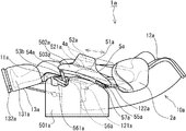
以下に、本発明のマッサージ椅子を、図面に示す一実施形態に基づきこれを詳細に説明する。図1は本発明のマッサージ椅子の一実施形態を示す斜視図であり、図2は本発明のマッサージ椅子の一実施形態を示す使用状態図である。また、図3は本発明のマッサージ椅子における背凭れ部と脚載部及び肘掛部の各動作に関する一実施形態を示す使用状態の右側面参考図であり、図4は本発明のマッサージ椅子の背凭れ部を後方へ倒伏させた一実施形態を示す使用状態の右側面参考図であり、図5は本発明のマッサージ椅子の肘掛部にスライド機構を備えた一実施形態を示す右側面参考図である。図6は本発明のマッサージ椅子における肘掛部のスライド機構による腕揉み機構の前後スライド動作に関する一実施形態を示す使用状態の右側面参考図であり、図7は本発明のマッサージ椅子の背凭れ部にスライド機構を備えた一実施形態を示す右側面参考図であり、図8は本発明のマッサージ椅子における背凭れ部のスライド機構による腕揉み機構の上下スライド動作に関する一実施形態を示す使用状態の右側面参考図であり、図9は本発明のマッサージ椅子の背凭れ部を倒伏させた状態での腕揉み機構のスライド動作に関する一実施形態を示す使用状態の右側面参考図であり、図10は本発明のマッサージ椅子の腕揉み機構における手部から上腕までの施療範囲に関する一実施形態を示す使用状態の右側面参考図であり、図11は本発明のマッサージ椅子における肘掛部の前端に設けたリンク部材を伸縮可能とした一実施形態を示す使用状態の右側面参考図である。また図12は本発明のマッサージ椅子における背凭れ部と肘掛部の各動作に関する一実施形態を示す右側面参考部分図であり、図13は本発明のマッサージ椅子における肘掛部の動作に関する一実施形態を示す右側面参考部分図である。図14は本発明のマッサージ椅子に挟み込み防止部材を設けた一実施形態を示す右側面参考部分図であり、図15乃至図17は本発明のマッサージ椅子に挟み込み防止部材を設けた一実施形態を示す正面参考部分図である。図18乃至図23は本発明のマッサージ椅子におけるリンク部材に固定手段を設けた一実施形態を示す右側面参考部分図であり、図24乃至図27は本発明のマッサージ椅子における肘掛部のスライド機構に固定手段を設けた一実施形態を示す右側面参考部分図であり、図28は本発明のマッサージ椅子における背凭れ部のスライド機構に固定手段を設けた一実施形態を示す右側面参考部分図であり、図29及び30は本発明のマッサージ椅子に回動スライド機構を設けた一実施形態を示す右側面参考部分図である。さらに図31は従来技術を示す参考図である。 Below, the massage chair of this invention is demonstrated in detail based on one Embodiment shown on drawing. FIG. 1 is a perspective view showing an embodiment of the massage chair of the present invention, and FIG. 2 is a use state diagram showing an embodiment of the massage chair of the present invention. FIG. 3 is a reference diagram on the right side of the usage state showing one embodiment of the backrest, leg rest and armrest operations in the massage chair of the present invention, and FIG. 4 is the back of the massage chair of the present invention. FIG. 5 is a right side reference diagram showing a state in which the bent portion is tilted backward, and FIG. 5 is a right side reference diagram showing an embodiment in which an armrest portion of the massage chair of the present invention is provided with a slide mechanism. is there. FIG. 6 is a right side reference view showing a working state of the armchair mechanism in the massage chair according to the present invention, which is related to the front and rear sliding movements of the armbing mechanism, and FIG. 7 is a backrest portion of the massage chair according to the present invention. FIG. 8 is a right side view showing an embodiment provided with a slide mechanism, and FIG. 8 is a view showing a use state showing an embodiment concerning an up and down slide operation of an arm kneading mechanism by a slide mechanism of a backrest portion in a massage chair of the present invention. FIG. 9 is a right side reference view of the massage chair according to the present invention, and FIG. 9 is a right side reference view of the use state showing an embodiment relating to the sliding operation of the arm massage mechanism with the backrest portion of the massage chair of the present invention lying down. FIG. 11 is a right side reference view of the usage state showing an embodiment relating to the treatment range from the hand portion to the upper arm in the arm massage mechanism of the massage chair of the present invention. FIG. Massage is a right side reference diagram using state showing an embodiment in which a telescopic link member provided on the front end of the armrest portion in the chair. FIG. 12 is a right side reference partial view showing an embodiment relating to each operation of the backrest and armrest in the massage chair of the present invention, and FIG. 13 is an embodiment relating to the operation of the armrest in the massage chair of the present invention. FIG. FIG. 14 is a right side reference partial view showing an embodiment in which the massage chair of the present invention is provided with a pinching prevention member, and FIGS. 15 to 17 show an embodiment in which the pinching prevention member is provided in the massage chair of the present invention. It is a front reference fragmentary figure shown. FIGS. 18 to 23 are right side reference partial views showing an embodiment in which fixing means are provided on the link member in the massage chair of the present invention, and FIGS. 24 to 27 are slide mechanisms of the armrests in the massage chair of the present invention. FIG. 28 is a right side reference partial view showing an embodiment in which a fixing means is provided on the slide mechanism of the backrest portion in the massage chair of the present invention. 29 and 30 are reference partial right side views showing an embodiment in which a rotating slide mechanism is provided in the massage chair of the present invention. FIG. 31 is a reference diagram showing the prior art.
本発明のマッサージ椅子1aは、図1乃至図3の実施形態で示したように、使用者の臀部が当接する座部11aと、該座部11aの後部で起立状態から倒伏状態へ起倒自在に配設された背凭れ部12aを配備すると共に、該座部11aの左右両側部には各々肘掛部5aを配設している。
As shown in the embodiment of FIGS. 1 to 3, the
すなわち、このマッサージ椅子1aは、座部11aの下部または側部には、フレームからなる基体56aが設けられており、該基体56aの後部に背凭れ部12aが起倒可能に取り付けられているものであり、前記肘掛部5aが、この基体56aの左右両側部に各々設けられて椅子本体10aを構成したものを例示している。
That is, the
また、詳細は後述するが、前記各肘掛部5a・5aは、下部の起立壁501aと、該起立壁501aの上部位置に配備されてこの上面503aに人体の手部または腕部等の被施療部を載置し得る可動肘掛部502aとに分割されており、該可動肘掛部502aには、前記被施療部を載置挿入し得る凹部52aが形成されていると共に、該凹部52a内に被施療部を施療し得る膨縮袋4aを配設した腕揉み機構51aが設けられている。
Although details will be described later, each of the
さらに、前記椅子本体10aの前部において、前記座部11aの下方位置から上下方向に回動移行する脚載部13aを備えている。
Furthermore, the front part of the said chair
また、前記背凭れ部12aには、左右両側に前方に向かって突出した側壁部2aを夫々配設している。
Further, the
図1に示すように、前記背凭れ部12aには、その中央部に左右一対の施療子31aを備えた昇降自在の施療子機構部3aを設けている。該施療子機構部3aは、背凭れ部12aの内部左右に設けた左右一対のガイドレール32aに沿って背凭れ部12aの上端から下端にかけて昇降するようにしている。
As shown in FIG. 1, the
前記左右一対の施療子31aは、モータ等を駆動源とした機械式のマッサージ機構であり、前記背凭れ部12aに凭れた使用者の首部、背部、腰部、臀部等の背面全域を、たたき、揉み、ローリング、振動、指圧などの多様な形態で施療するようにしたものである。
The pair of left and
また、前記マッサージ椅子1aの各所定の位置には、空気の給排気により膨縮を繰り返すことが可能な膨縮袋4aを夫々埋設している。該膨縮袋4aは、エアーコンプレッサー及び各膨縮袋4aに空気を分配するための分配器等からなる空気給排装置41aによる給排気により膨縮動作を行うようにしており、該空気給排装置41aは椅子本体10aの内部適所に配備している。
In addition, in each predetermined position of the
前記空気給排装置41aによる前記各膨縮袋4a・・の膨縮動作によって、使用者の所定の被施療部位を押圧、指圧等を実施することができ、一定間隔を存して対向するよう複数の膨縮袋4a・・を対設させた場合には、被施療部位に挟圧等の施療も行うことができる。
By the expansion / contraction operation of each expansion /
また、前記空気給排装置41aによる前記各膨縮袋4a・・の少なくとも1以上の膨縮袋4aを膨張状態に保つようにした場合は、使用者の所定の被施療部位を一定の時間保持することも可能にすることができる。
Further, when at least one or more of the inflatable and deflate
また、前記マッサージ椅子1aは、前記背凭れ部12aの左右側において、上部及び下部に夫々膨縮袋4aを設けており、使用者の背中及び腰部を押圧、または左右両側から挟圧するような施療を行うよう構成している。
The
また、前記座部11aには、後部側に臀下部用、また腿部用の膨縮袋4aを夫々埋設して、主に下方から上方に押圧する施療を行うようにしている。
In addition, in the
前記脚載部13aは、人体の脚部を施療するための施療機構を備えている。すなわち、該脚載部13aに人体脚部の脛部または足先部を夫々嵌入させる左右一対の凹部を夫々形成し、各凹部に膨縮袋4aを左右一対として対設するよう設けて、凹部内部で脛部及び足先部に対する挟圧施療を実施するようにしている。尚、適宜各凹部底部にも膨縮袋4aを設けることができる。
The said
また前記脚載部13aは、脛施療部131aと足先施療部132aとに分割形成したものとして構成しており、人体の脛部と足先部とを個別に施療することができるようにしている。
In addition, the
前記左右の側壁部2aは、座部11aに着座した使用者の肩または上腕側方となる位置に配設しており、該左右の側壁部2aの内側面には夫々左右方向に重合した膨縮袋4aを並列状態に埋設している。これら重合した膨縮袋4aはその基端部のみを側壁部2aの基端部に取り付けているため、膨張時には重合した膨縮袋4aが扇状に広がって使用者の身体側部を挟圧しつつ、身体前方まで覆うようになる。
The left and right
よって、前記左右側壁部2aの前記膨縮袋4aは、膨縮動作により身体側部を施療することができるだけでなく、一定の時間において膨張状態を保つならば、使用者の身体が前記背凭れ部12aから離れないようにしっかりと保持することができ、使用者の身体を固定したままの状態で前記施療子31aによる背部からの施療を効果的に受けることが可能となるのである。
Therefore, the
前記各肘掛部5aは、前述したように下部の起立壁501aと、該起立壁501aの上部位置に配備され、人体の手部または腕部を載置挿入し得る凹部52aが形成されていると共に該凹部52a内に手部または腕部を施療し得る膨縮袋4aが配設してある腕揉み機構51aを配備した可動肘掛部502aに分割されて構成するものであるが、これら起立壁501aの上前部と可動肘掛部502aの下前部間にリンク部材53aを介設すると共に該可動肘掛部502aの後部と背凭れ部12aの側部を枢着して可動肘掛部502aを揺動可能にし、背凭れ部12aの起倒動作に従って両肘掛部5aの各可動肘掛部5aが追従し得るようにしたものとしている。
Wherein each
前記腕揉み機構51aは前述のような膨縮袋4aを備えて、該膨縮袋4aの膨縮動作により人体の手部または腕部に対する施療を実施できるよう構成している。すなわち、正面視コ字型をなす前記凹部52aの内部において、その上下に該各膨縮袋4aを夫々対設させ、該凹部52aに嵌入した人体の手部または腕部に対する挟圧施療を実施するようにしている。尚、該凹部52aの形状として正面視U字型やL字型、また正面視C字型などがあげられるが、手部または腕部を嵌入保持できる凹部であればこれに限らない。
The
また、人体の手部または腕部を載置し得る前記可動肘掛部502aの上面は、前記腕揉み機構51aの凹部52aの底面521aを兼用するものとしている。
Further, the upper surface of the
さらに、前記可動肘掛部502aの後部と背凭れ部12aの側部との枢着位置は、背凭れ部12aのリクライニング回動軸121aよりも上位置である構成にしたものとしている。
Further, the pivot position between the rear portion of the
上記構成ゆえに、図3に示す背凭れ部12aが起立状態である場合の腕揉み機構51aにおける手部または腕部の姿勢は、図4に示す背凭れ部12aが起立状態である場合のその姿勢と略変化はしないので、背凭れ部12aのリクライニング角度が変化したとしても、常に腕揉み機構51aにおける適正な位置で手部または腕部に対する施療を施すことが可能となるのである。
Due to the above configuration, the posture of the hand or arm portion in the arm-resting
このような前記肘掛部5aの後方への移動に伴い、前記リンク部材53aはその下端に設けられた基体回動部561aを軸として後方へ回動する。この時、図3に示すように前記可動肘掛部502aの前端に設けられた前端回動部54aの高さ位置は前記背凭れ部12aが起立状態の時よりも低くなり、これと同様、可動肘掛部502aの後端に設けられた後端回動部55aの高さ位置も、背凭れ部12aの後方へのリクライニングに伴って低くなる。したがって、背凭れ部12aに仰臥または横臥した使用者の肘掛部5aに載置した手部または腕部が胴体よりも可及的に高く上がらないようにすることができ、リラックスした状態で腕揉み機構51aによる施療を受けることができる。
As the
図5及び図6に示すのは、前記可動肘掛部502aの後部における背凭れ部12aの側部との枢着位置に、可動肘掛部502aの位置を前後に位置調節し得るスライド機構57aを設けたものである。すなわち、前記後端回動部55aを前記可動肘掛部502aの前後方向に沿ってスライド可能となるよう、該可動肘掛部502aに該スライド機構57aを設けて構成する。この構成により、肘掛部5aの前記腕揉み機構51aは前記背凭れ部12aのリクライニングに関わらず、前後位置を自在に調節することが可能となる。
FIG. 5 and FIG. 6 show that a
例えば、前記腕揉み機構51aを後方へ位置調節する場合、前記後端回動部55aは前記スライド機構57aにおいて前方へスライドする形態となり、このスライドに伴って前記リンク部材53aは前記基体回動部561aを軸として後方へ回動することになる。
For example, when the position of the
図7乃至図9に示すのは、前記背凭れ部12aの側部における可動肘掛部502aの後部との枢着位置に、可動肘掛部502aの後部位置を上下に位置調節し得るスライド機構122aを設けたものである。すなわち、前記後端回動部55aを背凭れ部12aの長さ方向においてスライド可能となるよう、該背凭れ部12aに該スライド機構122aを設けて構成する。
FIG. 7 to FIG. 9 show a
この構成により、図8に示す前記背凭れ部12aが起立状態の場合は、前記腕揉み機構51aを背凭れ部12aの長さ方向に沿って移動させて、腕揉み機構51aの高さや角度を調節することができ、また図9に示す背凭れ部12aが倒伏状態の場合は、腕揉み機構51aの前後位置や角度を調節することができるようにしている。
With this configuration, when the
前述したような前記背凭れ部12aに設けたスライド機構122aと前記肘掛部5aに設けた前記スライド機構57aと併用する場合は、前記腕揉み機構51aの前後位置や高さ位置、また角度における調節範囲及び手部や腕部に対する施療範囲がさらに拡大することになる。
When the
図10及び図13に示す構成は、前記リンク部材53aを前述のものよりも長く形成することにより、前記背凭れ部12aを起立させた状態であっても、手部から前腕部、肘部、上腕部までの広範な施療部位を施療することができるものである。
10 and 13, the
例えば、前記腕揉み機構51aに最前端に位置する状態から後方へ移動させるための力を加えると、前記後端回動部55aは前記可動肘掛部502aの前記スライド機構57aにおける最前端まで移動する。その後、さらに腕揉み機構51aに後方へ力を加えると、今度は前記背凭れ部12aの前記スライド機構122aに沿って後端回動部55aは上方へ移動することになる。このようにして腕揉み機構51aは、背凭れ部12aが起立状態の場合に着座した使用者の腕部の態様が屈曲したものであっても、手部から前腕部、また肘部から上腕部まで、その肢体のラインに沿って移動することができる。尚、可動肘掛部502aや腕揉み機構51aが背凭れ部12aの前記側壁部2aと干渉のないよう構成したり、または該側壁部2aを設けない構成にしたりすることにより、腕揉み機構51aが使用者の肩部まで到達するよう背凭れ部12aのスライド機構122aを長く設けることができる。
For example, when a force for moving backward from a state positioned at the foremost end is applied to the
前記リンク部材53aを長く形成する構成の他に、これを伸縮可能にすることによっても、前記腕揉み機構51aの移動範囲をさらに拡大させることができる。一例として、図11に示すような折り畳み式の伸縮リンク部材53bを採用できる。
In addition to the structure in which the
例えば、前記腕揉み機構51aが最前端位置の場合は該伸縮リンク部材53bは折り畳まれて縮小し、腕揉み機構51aが最後端の場合は伸縮リンク部材53bは伸張した状態となる。この構成により、手部や前腕だけでなく、肘部や上腕などに至るまで腕揉み機構51aによる施療範囲を広げられる。
For example, when the
前記可動肘掛部502aの前記スライド機構57aや前記背凭れ部12aのスライド機構122aのスライド、及び前記リンク部材53aや伸縮リンク部材53bの回動において、段階または無段階に、手動或いはモータなどの自動で調節できるようにしてもよい。例えばそのような位置調節を段階的に行う構成として、ラチェット機構などを適用することができる。尚、手動の場合は油圧シリンダを、電動の場合は電動アクチュエータを介装できる。さらには、センサーによる使用者の手腕の長さを検知して自動調節するよう構成してもよい。
In the slide of the
また、図示していないが、前記スライド機構57aまたは/及びスライド機構122aを、その調節方向に設けた多数の溝と係合突起とで構成したものを採用できる。例えば、前記可動肘掛部502aの後部を上または前に動かすと係合突起は溝から外れて前記後端回動部55aはスライド機構57aまたは/及びスライド機構122aにおいて移動可能となり、可動肘掛部502aにかかる手部または腕部の重さで係合突起は再び溝に填って係止するように構成することができる。
Although not shown, the
さらに、図6に示すように、例えば前記リンク部材53aを前記基体回動部561aが基軸として前後交互に回動させるようにする場合においては、電動モータなどによる自動でその交互の回動を連続的に行うようにすることで、前記腕揉み機構51aにおける使用者の手部または腕部の位置を連続的に移動させながら該手部または腕部を摺擦しつつ揉むことが可能となる。
Further, as shown in FIG. 6, for example, in the case where the
尚、上記の本発明におけるマッサージ椅子1aは、前記スライド機構57aまたはスライド機構122aを設けるものであっても、該腕揉み機構51aを背凭れ部12aのリクライニング動作に追従するよう構成されている。
The
図14乃至図16及び図18に示す構成は、前記可動肘掛部502aと前記起立壁501aとの間、または可動肘掛部502aと前記基体56aとの間、或いは可動肘掛部502aと前記座部11aとの間に、人体の一部が挟み込まれて痛みや怪我をもたらさないよう防止するための挟み込み防止部材58aを可動肘掛部502aの幅方向内側に設けたものである。
14 to 16 and 18, the
図面に示すように、前記挟み込み防止部材58aとして前記可動肘掛部502aと前記起立壁501aとの間に存する空間を遮蔽することができる板状の形態のものを採用することができる。
As shown in the drawing, a plate-shaped member that can shield the space between the
よって、図16に示すように前記可動肘掛部502aの前記起立壁501aに対する上下動作に関わらず、常時、前記挟み込み防止部材58aによる遮蔽がなされ、人体の一部を挟み込む要因を除去することができる。
Therefore, as shown in FIG. 16, regardless of the vertical movement of the
図17に示す構成は、前記挟み込み防止部材58aを前記可動肘掛部502aの幅方向外側にも設けたものである。これにより、前記座部11aに着座した使用者だけでなく外部から接近してくる人も、可動肘掛部502aの動作により挟み込むことがないよう保護することができる。
In the configuration shown in FIG. 17, the pinching
上記において説明した本発明のマッサージ椅子1aは、図18に示すように前記基体56aと前記リンク部材53aとを回動可能に連結する前記基体回動部561aにおいて、該リンク部材53aをその回動範囲における所定の位置で固定するための固定手段6a(ロック機構)を設けている。
As shown in FIG. 18, the
前記固定手段6a(ロック機構)は、前記基体56aに固設された円弧歯を形成するラック61aと、前記リンク部材53aの中間部に固設され、該ラック61aに係合する係合ピン62aとから構成したものを例示している。
The fixing means 6a (lock mechanism) includes a
また、前記ラック61aの下部には、前記基体回動部561aがスライドするためのスライド溝611aを設けているため、前記リンク部材53aは該スライド溝611aに沿ってスライドできるようになっている。
In addition, a
前記固定手段6a(ロック機構)は、上記したように構成されているため、前記腕揉み機構51aの位置調節の際、使用者が所望する位置において該腕揉み機構51aを前記背凭れ部12aの起倒に影響されず、確実に固定することができるのである。尚、前記係合ピン62aの前記ラック61aに対する係合を解除することにより、前述で説明したように前記背凭れ部12aの起倒動作に腕揉み機構51aが連動する。
Since the fixing means 6a (locking mechanism) is configured as described above, when adjusting the position of the
例えば、前記腕揉み機構51aの位置調節を行う場合、まず図19に示すように前記可動肘掛部502aの前端部を持ち上げると、前記ラック61aに係合している前記係合ピン62aは上方へ移動するので、該ラック61aに対する係合ピン62aの係合は解除される。
For example, when adjusting the position of the
次いで、図20に示すように前記腕揉み機構51aの前後における位置調節移動が可能となり、使用者が所望する位置まで腕揉み機構51aを移動させる。
Next, as shown in FIG. 20, the position adjustment movement before and after the
その後、図21に示すように前記可動肘掛部502aの前端部を押し下げるかまたは荷重をかけることにより、再び前記ラック61aに前記係合ピン62aが係合し、前記基体56aに対する前記腕揉み機構51aを固定することができる。
Thereafter, as shown in FIG. 21, by pushing down or applying a load to the front end of the
図22及び図23は、前記固定手段6a(ロック機構)における固定及び解除を操作レバー63aによって行う構成のものである。すなわち、前記係合ピン62aの前記ラック61aに対する係合を保持するための係合保持機構64aを前記リンク部材53aに設けると共に、前記操作レバー63aと係合保持機構64aとの間に動作伝達ケーブル67aを介設して構成している。尚、この構成の場合、該係合ピン62aはリンク部材53aに固設されておらず、係合保持機構64aによりラック61aに対する係合または解除を行うようにしている。
22 and 23 show a configuration in which the fixing means 6a (lock mechanism) is fixed and released by the
さらに、前記係合保持機構64aは、前記係合ピン62aを押し下げたり、または引き上げたりするためのロッド65aと、該ロッド65aが係合ピン62aを常時押し下げて前記ラック61aに係合させるための付勢手段となる付勢バネ66aとで構成している。
Further, the
よって、図23に示すように前記操作レバー63aを上方へ引き上げると、前記係合保持機構64aの前記付勢バネ66aの付勢力に反して前記動作伝達ケーブル67aは上方へ引っ張られるため、前記ロッド65aは前記係合ピン62aと共に上方へ移動することになり、該係合ピン62aは前記ラック61aに対する係合が解除される。その後、前記腕揉み機構51aを所望する位置になるよう前後において移動させてから、操作レバー63aを離すと付勢バネ66aの付勢力によって係合ピン62aは再びラック61aに係合することになる。
Therefore, when the
図24に示す本発明における構成は、前記肘掛部5aに設けた前記スライド機構57aに、該スライド機構57aによる前記腕揉み機構51aの位置調節後の位置固定を行うための固定手段6a(ロック機構)を設けたものである。すなわち該固定手段6a(ロック機構)として、ラック61aを該スライド機構57aに備えると共に、前記後端回動部55aに連結する係合ピン62aを該ラック61aに係合するよう構成している。
The configuration in the present invention shown in FIG. 24 is that fixing means 6a (lock mechanism) for fixing the position of the
前記スライド機構57aの前記ラック61aに対する前記係合ピン62aの係合または解除は、前記可動肘掛部502aの後端部を上下に押し引きするなどしてなされるよう構成できる。例えば、図25に示すように、可動肘掛部502aの後端部を引き上げると、係合ピン62aのラック61aにおける係合が解除され、次いで図26に示すように前記腕揉み機構51aが適正位置になるよう位置調節を行い、その後、図27に示すように、可動肘掛部502aの後端部を押し下げるか、または荷重をかけるかをすることにより、再び係合ピン62aはラック61aに係合し、腕揉み機構51aの位置が固定されるのである。
The
図27に示す構成は、前記背凭れ部12aに設けた前記スライド機構122aに、該スライド機構122aによる前記腕揉み機構51aの位置調節後の位置固定を行うための固定手段6a(ロック機構)を設けたものである。すなわち該固定手段6a(ロック機構)として、ラック61aを該スライド機構122aに備えると共に、前記後端回動部55aに連結する係合ピン62aを該ラック61aに係合するよう構成している。
In the configuration shown in FIG. 27, the
前記スライド機構122aにおける前記係合ピン62aの前記ラック61aに対する係合または解除、また該解除時における前記腕揉み機構51aの位置調節は、前述した前記肘掛部5aに設けた前記スライド機構57aにおける前記固定手段6a(ロック機構)と同様であり、前記可動肘掛部502aの後端部を上下に押し引きするなどして係合ピン62aの係合または解除がなされるものであり、前記腕揉み機構51aの位置調節後、可動肘掛部502aの後端部を押し下げるか、または荷重をかけるかをすることにより、係合ピン62aはラック61aに係合して腕揉み機構51aの位置が固定されるのである。
The
図29及び図30は、前記肘掛部5aに設けた前記スライド機構57aと、前記背凭れ部12aに設けた前記スライド機構122aとの夫々の機能を組み合わせた単一の機構として回動スライド機構7aを前記椅子本体10aに設けたものを例示している。
29 and 30 show a
すなわち、前記後端回動部55aを前記回動スライド機構7aの回動中心より偏心させた位置に設けており、該回動スライド機構7aの回動により、図30に示すように前記腕揉み機構51aの上下または左右位置、及び角度を自在に調節することができるのである。尚、該回動スライド機構7aを電動、または手動の駆動手段73aにより回動するよう構成している。
That is, the rear
具体的には、前記背凭れ部12aの左右両側に夫々大歯車71aを設けると共に、左右の該各大歯車71aが同期回転するための同期回転制御歯車72aを、大歯車71aと前記駆動手段73aとの間に介設することができる。
Specifically, a
よって、前記駆動手段73aの回転が前記同期回転制御歯車72aを介して前記大歯車71aに伝達されることにより、前記後端回動部55aの位置移動が可能となる。
Therefore, the rotation of the driving means 73a is transmitted to the
尚、前記駆動手段73aを連続的に回転させることで、前記可動肘掛部502a上に載置する使用者の手部または腕部、また上腕部や肩部周辺の部位を動かしつつ解すような施療作用をもたらすことができるものとなり、さらには前記腕揉み機構51aにおける前記膨縮袋4aの膨縮動作、または膨張保持と併用することにより、被施療部の位置を周期的に変更しながら満遍なく施療を行ったり、或いは被施療部に対する摺擦効果をもたらしたりすることもできるものとなる。
It is to be noted that the treatment is such that the user's hand or arm placed on the
1a マッサージ椅子
10a 椅子本体
11a 座部
12a 背凭れ部
121a リクライニング回動軸
122a スライド機構
13a 脚載部
131a 脛施療部
132a 足先施療部
2a 側壁部
3a 施療子機構部
31a 施療子
32a ガイドレール
4a 膨縮袋
41a 空気給排装置
5a 肘掛部
501a 起立壁
502a 可動肘掛部
503a 上面
51a 腕揉み機構
52a 凹部
521a 底面
53a リンク部材
53b 伸縮リンク部材
54a 前端回動部
55a 後端回動部
56a 基体
561a 基体回動部
57a スライド機構
58a 挟み込み防止部材
6a 固定手段(ロック機構)
61a ラック
611a スライド溝
62a 係合ピン
63a 操作レバー
64a 係合保持機構
65a ロッド
66a 付勢バネ
67a 動作伝達ケーブル
7a 回動スライド機構
71a 大歯車
72a 同期回転制御歯車
73a 駆動手段
DESCRIPTION OF
Claims (6)
前記各肘掛部は、下部の起立壁と、該起立壁の上部位置に配備され、人体の手部または腕部を載置挿入し得る凹部が形成されていると共に該凹部内に手部または腕部を施療し得る膨縮袋が配設してある腕揉み機構を配備した可動肘掛部に分割されており、
これら起立壁上前部と可動肘掛部下前部間にリンク部材を介設すると共に該可動肘掛部後部と背凭れ部側部を枢着して可動肘掛部を揺動可能にし、背凭れ部の起倒動作に従って両肘掛部の各可動肘掛部が追従し得るよう構成し、
前記可動肘掛部の幅方向内側には、前記可動肘掛部と前記起立壁との間に存する空間を遮蔽することができる板状の形態の挟み込み防止部材を設け、
前記可動肘掛部の前記起立壁に対する上下動作に関わらず、常時、前記挟み込み防止部材による遮蔽がなされ、人体の一部を挟み込む要因を除去することができる事を特徴するマッサージ椅子。
A massage chair provided with a backrest provided so as to be able to rise and fall from a standing state to a lying state at the rear part of the seat part, and provided with armrests on both the left and right sides of the seat part,
Wherein each armrest includes a lower portion of the upright wall, it is deployed in the upper position of the standing upright wall, the hand or in the recess with the recess that may be placed insert a human hand portion or arm portion is formed The arm is divided into movable armrests that are equipped with an arm massaging mechanism in which an inflatable bag that can treat the arm is disposed,
A link member is interposed between the upper front part of the standing wall and the lower front part of the movable armrest part, and the movable armrest part can be pivoted by pivotally attaching the rear part of the movable armrest part and the backrest side part. Configured so that each movable armrest of both armrests can follow in accordance with the up and down motion,
On the inner side in the width direction of the movable armrest portion, a pinch- shaped pinching prevention member capable of shielding the space existing between the movable armrest portion and the standing wall is provided,
Regardless of the vertical movement of the movable armrest portion with respect to the standing wall, the massage chair is characterized in that it is always shielded by the pinching prevention member and can eliminate the cause of pinching a part of the human body .
前記肘掛部の後方への移動に伴い、前記リンク部材はその下端に設けられた基体回動部を軸として後方へ回動して、前記可動肘掛部の前端に設けられた前端回動部の高さ位置は前記背凭れ部が起立状態の時よりも低くなり、可動肘掛部の後端に設けられた後端回動部の高さ位置も、背凭れ部の後方へのリクライニングに伴って低くなることを特徴する請求項1記載のマッサージ椅子。
The pivot position of the movable armrest rear part and the backrest side part is an upper position than the reclining rotation axis of the backrest part,
As the armrest is moved rearward, the link member is rotated rearward around a base rotation portion provided at the lower end of the link member, and a front end rotation portion provided at the front end of the movable armrest is provided. The height position is lower than when the backrest is in the standing state, and the height position of the rear end rotation part provided at the rear end of the movable armrest is also accompanied by reclining to the back of the backrest. The massage chair according to claim 1, wherein the massage chair is lowered.
The massage mechanism according to claim 1 or 2, wherein a slide mechanism capable of adjusting the position of the movable armrest portion back and forth is provided at a pivot position with the backrest side portion at the rear portion of the movable armrest portion. Chair.
The slide mechanism which can adjust a movable armrest rear part position up and down is provided in the pivoting position with the rear part of the movable armrest part in the backrest part side part. Massage chair according to crab.
The massage chair according to claim 1, wherein the link member or the slide mechanism is provided with a fixing means capable of fixing the position of the movable armrest portion.
Priority Applications (1)
| Application Number | Priority Date | Filing Date | Title |
|---|---|---|---|
| JP2007013174A JP5289711B2 (en) | 2007-01-23 | 2007-01-23 | Massage chair |
Applications Claiming Priority (1)
| Application Number | Priority Date | Filing Date | Title |
|---|---|---|---|
| JP2007013174A JP5289711B2 (en) | 2007-01-23 | 2007-01-23 | Massage chair |
Publications (2)
| Publication Number | Publication Date |
|---|---|
| JP2008178491A JP2008178491A (en) | 2008-08-07 |
| JP5289711B2 true JP5289711B2 (en) | 2013-09-11 |
Family
ID=39722853
Family Applications (1)
| Application Number | Title | Priority Date | Filing Date |
|---|---|---|---|
| JP2007013174A Active JP5289711B2 (en) | 2007-01-23 | 2007-01-23 | Massage chair |
Country Status (1)
| Country | Link |
|---|---|
| JP (1) | JP5289711B2 (en) |
Families Citing this family (15)
| Publication number | Priority date | Publication date | Assignee | Title |
|---|---|---|---|---|
| JP5232116B2 (en) * | 2009-09-25 | 2013-07-10 | パナソニック株式会社 | Massage machine |
| JP5232117B2 (en) * | 2009-09-25 | 2013-07-10 | パナソニック株式会社 | Massage machine |
| JP6013165B2 (en) | 2012-12-11 | 2016-10-25 | 株式会社フジ医療器 | Massage chair |
| JP2015016158A (en) * | 2013-07-11 | 2015-01-29 | 大東電機工業株式会社 | Chair type massage machine |
| JP6499502B2 (en) * | 2014-07-29 | 2019-04-10 | 株式会社フジ医療器 | Chair massage machine |
| KR102063400B1 (en) * | 2018-05-25 | 2020-01-07 | 주식회사 바디프랜드 | Massage device with adjustable angle of shoulder massage part |
| JP7150592B2 (en) * | 2018-12-26 | 2022-10-11 | 株式会社フジ医療器 | chair massage machine |
| JP1653917S (en) * | 2019-01-08 | 2020-03-02 | ||
| USD923351S1 (en) * | 2019-04-19 | 2021-06-29 | Xiamen Mas-Agee Electronic Technology Co., Ltd. | Massage chair |
| USD946916S1 (en) * | 2019-07-12 | 2022-03-29 | Woongjin Coway Co., Ltd. | Massage chair |
| KR102371403B1 (en) * | 2020-07-15 | 2022-03-08 | 주식회사 바디프랜드 | Massage apparatus having rotatable arm massage unit |
| CN215536223U (en) * | 2020-07-15 | 2022-01-18 | 保迪弗兰德有限公司 | Massage device |
| CN111920669A (en) * | 2020-08-05 | 2020-11-13 | 郑州工业应用技术学院 | A recovery device for gynaecology postpartum |
| CN115054477B (en) * | 2022-05-07 | 2023-07-07 | 浙江豪中豪健康产品有限公司 | Four-bar damping groove handrail opening and closing mechanism with lock catch |
| KR102690982B1 (en) * | 2023-09-14 | 2024-08-05 | 주식회사 바디프랜드 | Massage apparatus capable of adjusting the position of the arm massage unit |
Family Cites Families (6)
| Publication number | Priority date | Publication date | Assignee | Title |
|---|---|---|---|---|
| JP4056285B2 (en) * | 2002-04-19 | 2008-03-05 | ファミリー株式会社 | Massage machine |
| JP4074793B2 (en) * | 2002-08-21 | 2008-04-09 | テイ・エス テック株式会社 | Multipurpose chair armrest |
| JP4194904B2 (en) * | 2002-12-27 | 2008-12-10 | ファミリー株式会社 | Chair type massage device |
| JP3969388B2 (en) * | 2003-12-22 | 2007-09-05 | 松下電工株式会社 | Chair massage machine |
| JP4286183B2 (en) * | 2004-05-24 | 2009-06-24 | 株式会社クボタ | Armrest device |
| JP4418532B2 (en) * | 2004-10-05 | 2010-02-17 | ファミリー株式会社 | Chair type massage machine |
-
2007
- 2007-01-23 JP JP2007013174A patent/JP5289711B2/en active Active
Also Published As
| Publication number | Publication date |
|---|---|
| JP2008178491A (en) | 2008-08-07 |
Similar Documents
| Publication | Publication Date | Title |
|---|---|---|
| JP5289711B2 (en) | Massage chair | |
| JP5279190B2 (en) | Massage chair | |
| US20070016119A1 (en) | Chair-type massage machine, cover for massage machine, cover for ottoman, and massage machine | |
| JP5785676B2 (en) | Massage machine | |
| KR102058242B1 (en) | Massage chair with stretch functions | |
| JP4320196B2 (en) | Resting chair type treatment machine | |
| JP4037674B2 (en) | Chair | |
| JP4917358B2 (en) | Treatment machine | |
| JP5408744B2 (en) | Massage machine | |
| KR100739020B1 (en) | Lumber traction apparatus | |
| JP4866720B2 (en) | Chair massage machine | |
| JP4919290B2 (en) | Massage machine | |
| JP4865448B2 (en) | Chair massage machine | |
| KR102002423B1 (en) | A inversion apparatus having chair function | |
| JP5144794B2 (en) | Chair massage machine | |
| KR20060128702A (en) | Flexible seat chair capable of adjusting the angle between the respective parts | |
| JP2007330345A (en) | Treatment machine | |
| JP2000175774A (en) | Chair/bed device | |
| JP5563548B2 (en) | Massage machine | |
| JP4453564B2 (en) | Massage chair | |
| CN110584892A (en) | Flat wheelchair of lying | |
| JP3602188B2 (en) | Dental treatment chair | |
| JP2004024886A (en) | Chair having double footrest | |
| JP6049336B2 (en) | Massage machine | |
| JP5116318B2 (en) | Chair massage machine |
Legal Events
| Date | Code | Title | Description |
|---|---|---|---|
| A621 | Written request for application examination |
Free format text: JAPANESE INTERMEDIATE CODE: A621 Effective date: 20091228 |
|
| A977 | Report on retrieval |
Free format text: JAPANESE INTERMEDIATE CODE: A971007 Effective date: 20111114 |
|
| A131 | Notification of reasons for refusal |
Free format text: JAPANESE INTERMEDIATE CODE: A131 Effective date: 20111213 |
|
| A521 | Request for written amendment filed |
Free format text: JAPANESE INTERMEDIATE CODE: A523 Effective date: 20120210 |
|
| A131 | Notification of reasons for refusal |
Free format text: JAPANESE INTERMEDIATE CODE: A131 Effective date: 20120911 |
|
| A521 | Request for written amendment filed |
Free format text: JAPANESE INTERMEDIATE CODE: A523 Effective date: 20121109 |
|
| TRDD | Decision of grant or rejection written | ||
| A01 | Written decision to grant a patent or to grant a registration (utility model) |
Free format text: JAPANESE INTERMEDIATE CODE: A01 Effective date: 20130528 |
|
| A61 | First payment of annual fees (during grant procedure) |
Free format text: JAPANESE INTERMEDIATE CODE: A61 Effective date: 20130605 |
|
| R150 | Certificate of patent or registration of utility model |
Ref document number: 5289711 Country of ref document: JP Free format text: JAPANESE INTERMEDIATE CODE: R150 |
|
| R250 | Receipt of annual fees |
Free format text: JAPANESE INTERMEDIATE CODE: R250 |
|
| R250 | Receipt of annual fees |
Free format text: JAPANESE INTERMEDIATE CODE: R250 |
|
| R250 | Receipt of annual fees |
Free format text: JAPANESE INTERMEDIATE CODE: R250 |
|
| R250 | Receipt of annual fees |
Free format text: JAPANESE INTERMEDIATE CODE: R250 |
|
| R250 | Receipt of annual fees |
Free format text: JAPANESE INTERMEDIATE CODE: R250 |
|
| R250 | Receipt of annual fees |
Free format text: JAPANESE INTERMEDIATE CODE: R250 |
|
| R250 | Receipt of annual fees |
Free format text: JAPANESE INTERMEDIATE CODE: R250 |
|
| R250 | Receipt of annual fees |
Free format text: JAPANESE INTERMEDIATE CODE: R250 |
|
| R250 | Receipt of annual fees |
Free format text: JAPANESE INTERMEDIATE CODE: R250 |