EP2015977B1 - Lenkradaufhängungssystem - Google Patents
Lenkradaufhängungssystem Download PDFInfo
- Publication number
- EP2015977B1 EP2015977B1 EP07748056.4A EP07748056A EP2015977B1 EP 2015977 B1 EP2015977 B1 EP 2015977B1 EP 07748056 A EP07748056 A EP 07748056A EP 2015977 B1 EP2015977 B1 EP 2015977B1
- Authority
- EP
- European Patent Office
- Prior art keywords
- steering wheel
- suspension system
- wheel suspension
- console
- box construction
- Prior art date
- Legal status (The legal status is an assumption and is not a legal conclusion. Google has not performed a legal analysis and makes no representation as to the accuracy of the status listed.)
- Not-in-force
Links
- 239000000725 suspension Substances 0.000 title claims description 50
- 238000010276 construction Methods 0.000 claims description 25
- 210000003127 knee Anatomy 0.000 claims description 24
- 230000004913 activation Effects 0.000 claims description 8
- 230000008878 coupling Effects 0.000 claims description 6
- 238000010168 coupling process Methods 0.000 claims description 6
- 238000005859 coupling reaction Methods 0.000 claims description 6
- 230000006378 damage Effects 0.000 claims description 6
- 238000006073 displacement reaction Methods 0.000 claims description 3
- 210000001331 nose Anatomy 0.000 description 7
- 208000027418 Wounds and injury Diseases 0.000 description 5
- 208000014674 injury Diseases 0.000 description 5
- 230000001419 dependent effect Effects 0.000 description 1
- 238000012986 modification Methods 0.000 description 1
- 230000004048 modification Effects 0.000 description 1
- 230000007935 neutral effect Effects 0.000 description 1
Images


Classifications
-
- B—PERFORMING OPERATIONS; TRANSPORTING
- B62—LAND VEHICLES FOR TRAVELLING OTHERWISE THAN ON RAILS
- B62D—MOTOR VEHICLES; TRAILERS
- B62D1/00—Steering controls, i.e. means for initiating a change of direction of the vehicle
- B62D1/02—Steering controls, i.e. means for initiating a change of direction of the vehicle vehicle-mounted
- B62D1/16—Steering columns
- B62D1/18—Steering columns yieldable or adjustable, e.g. tiltable
- B62D1/19—Steering columns yieldable or adjustable, e.g. tiltable incorporating energy-absorbing arrangements, e.g. by being yieldable or collapsible
- B62D1/195—Yieldable supports for the steering column
-
- B—PERFORMING OPERATIONS; TRANSPORTING
- B60—VEHICLES IN GENERAL
- B60R—VEHICLES, VEHICLE FITTINGS, OR VEHICLE PARTS, NOT OTHERWISE PROVIDED FOR
- B60R21/00—Arrangements or fittings on vehicles for protecting or preventing injuries to occupants or pedestrians in case of accidents or other traffic risks
- B60R21/02—Occupant safety arrangements or fittings, e.g. crash pads
- B60R21/04—Padded linings for the vehicle interior ; Energy absorbing structures associated with padded or non-padded linings
- B60R21/05—Padded linings for the vehicle interior ; Energy absorbing structures associated with padded or non-padded linings associated with the steering wheel, steering hand lever or steering column
-
- B—PERFORMING OPERATIONS; TRANSPORTING
- B62—LAND VEHICLES FOR TRAVELLING OTHERWISE THAN ON RAILS
- B62D—MOTOR VEHICLES; TRAILERS
- B62D1/00—Steering controls, i.e. means for initiating a change of direction of the vehicle
- B62D1/02—Steering controls, i.e. means for initiating a change of direction of the vehicle vehicle-mounted
- B62D1/16—Steering columns
- B62D1/18—Steering columns yieldable or adjustable, e.g. tiltable
- B62D1/19—Steering columns yieldable or adjustable, e.g. tiltable incorporating energy-absorbing arrangements, e.g. by being yieldable or collapsible
- B62D1/197—Steering columns yieldable or adjustable, e.g. tiltable incorporating energy-absorbing arrangements, e.g. by being yieldable or collapsible incorporating devices for preventing ingress of the steering column into the passengers space in case of accident
-
- B—PERFORMING OPERATIONS; TRANSPORTING
- B60—VEHICLES IN GENERAL
- B60R—VEHICLES, VEHICLE FITTINGS, OR VEHICLE PARTS, NOT OTHERWISE PROVIDED FOR
- B60R21/00—Arrangements or fittings on vehicles for protecting or preventing injuries to occupants or pedestrians in case of accidents or other traffic risks
- B60R2021/003—Arrangements or fittings on vehicles for protecting or preventing injuries to occupants or pedestrians in case of accidents or other traffic risks characterised by occupant or pedestian
- B60R2021/0039—Body parts of the occupant or pedestrian affected by the accident
- B60R2021/0051—Knees
Definitions
- the present invention relates to a steering wheel suspension system for reducing the risk of injury to the driver in connection with vehicle collisions.
- the system includes a steering wheel axle, steering wheel shaft in which the steering wheel axle is rotatably carried.
- the system includes a steering wheel and a knee bar at one end of the steering wheel axle.
- EP 0 757 946 discloses the preamble of claim 1, a steering wheel suspension system that subjects the steering wheel to a downward motion when a collision occurs. No displacement of the steering wheel in direction towards the driver occurs.
- EP 0 252 discloses a steering wheel suspension system that is especially adapted to be used with an airbag.
- the system comprises energy absorbing means.
- US patent no. 6,220,630 shows a steering wheel suspension system in which the steering wheel axle is carried in a holder device that preferably is arranged under the instrument panel of a vehicle.
- the steering wheel suspension system includes two electric motors to adjust the position of the steering wheel axle so that both the depth and height adjustments can be done.
- the electric motors rotate in the cogwheel of the steering wheel suspension system that cooperates with cog bars to accomplish the necessary shifting in connection with the adjustment of the position of the steering wheel axle.
- the steering wheel suspension system according to US-A-6,220,630 also includes members to reduce the risk for injuries to the driver.
- the members include a swingable suspended knee bar that the knees of the driver push forwardly during a collision.
- the knee bar is connected to the housings of the electric motors via an energy-absorbing link.
- the housings of the electric motors carry out a rotational movement once a certain predetermined force is achieved and security members, such as breakable pins, are released.
- a primary object of the present invention is to develop a steering wheel suspension system as defined in the introduction above so that the design of steering wheel suspension system is very simple while being fully functional.
- a further object of the present invention is that the adjustment of the position of the steering wheel axle should be extremely simple to carry out.
- Another object of the present invention is that the shifting of the knee bar that is included in the steering wheel suspension system is directly transferred to a shifting of the steering wheel axle.
- At least the primary object of the present invention is realized by a steering wheel suspension system that is described in the appended independent patent claim 1.
- Preferred embodiments of the invention are defined in the dependent patent claims.
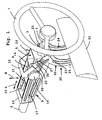
- the steering wheel suspension system according to the present invention has a length direction, which in Fig. 1 , is defined by the double arrow L and a height direction, which in Fig. 1 , is defined by the double arrow H.
- the steering wheel suspension system according to the present invention includes the steering wheel axle 1 which is carried in a steering wheel shaft 3 that includes a sleeve.
- the steering wheel axle 1 is rotatably mounted relative to the steering wheel shaft 3 that is fixed, such as welded, in a box construction 5.
- a steering wheel 7 is arranged at one end of the steering wheel axle.
- the box construction 5 is connected to a console 9 that extends in the length direction of the steering wheel shaft 3.
- the box construction 5 has first and second slits 8, 10, respectively that extend in the length direction L of the steering wheel suspension system.
- the console is equipped with transverse first shafts 11 that are received in the second slits 10.
- the console 9 has a first attachment 12 and a second attachment 13 so that the attachments are plane surfaces in the preferred embodiment.
- the console 9 is attached, via the attachments 12, 13 in a suitable way to the chassis of the vehicle so that the console is positioned below the instrument panel.
- slits 14 In connection with the first attachment 12 in the console 9 there are three slits 14 of which only one is partly shown in Fig. 1 .
- a second slit is hidden by a rotatably know 15 that is mounted on a second shaft 16, see Fig .2 , that extends through both the first slits 8 and the third slits 14.
- the slits 14 generally extend in the height direction H of the steering wheel suspension system.
- the arrangement of the bars 11, 16 and the slits 8, 10, 14 make it possible to shift the box construction 5 relative to the console 9 in the length direction L of the steering wheel suspension system.
- the second bar 16 also extends through a first arm 17 in the area of one end of the first arm 17.
- the second end of the first arm 17 is rotatably attached to the console 9 in the area of the console that is located further away from the steering wheel 7.
- the rotatable knob 15 and the second bar 15 are also provided with some sort of nut arrangement that is situated on the side of the console that is hidden in the figures.
- the rotatable knob 15, the bar 16 and the nut arrangement cooperate in such a way that the when the rotatable know is rotated in a certain direction the console is clamped around the box construction 5 so that a friction coupling is generated between the console 9 and the box construction 5.
- the rotatable know 15 rotates in the opposite direction the friction coupling is terminated between the console 9 and the box construction 5.
- the steering wheel suspension system in the area of the end of the console 9 that is turned toward the steering wheel 7 the steering wheel suspension system according to the present invention includes a knee bar 20 that includes a pillow 21 and an activation member 22 that supports the pillow 21.
- the activation member is in the form of an arm unit that via a link 23 is rotatably attached to the console 9.
- the link 23 is a stationary point because it is arranged in the stationary console 9.
- the arm unit 22 includes two first arm portions 24 that extend between the pillow 21 and the link 23 and two second arm portions 25 that extend from the link 23 and each terminating with free ends. In the area of the free end of each of the second arm portions 25 the arm unit 22 is shaped with a nose 26 which function is described below.
- the arm unit 22 thus includes two noses 26. Inside the noses 26 each-of the second arm portions 25 includes with a contact surface 27 which function is described below.
- the box construction 5 is in the area of the end that is turned towards the steering wheel 7 provided with two protrusions 30 of which only one is shown in the figures.
- the protrusions are adapted to cooperate with the arm unit 22 and more particularly with the noses 26 of the arm unit 22.
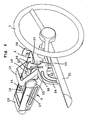
- Figs. 1 and 2 illustrate how the steering wheel suspension system according to the present invention can be adjusted regarding the position of the steering wheel axle 1/steering wheel 7.
- Fig. 1 shows a neutral position for the steering wheel axle 1/steering wheel 7 of the steering wheel suspension system according to the present invention while
- Fig. 2 shows a position for the steering wheel axle/steering wheel 7 where the steering wheel axle 1 is shifted towards the driver and raised compared to the position according to Fig. 1 .
- the friction coupling between the console 9 and the box construction 5 is released by rotating the knob 15.
- the box construction 5 can now be shifted in the direction towards the knee bar 20.
- the primary function of the steering wheel suspension system according to the present invention is to reduce the risk for injuries to the driver in connection with a vehicle collision.
- the steering wheel suspension system of the present invention has a knee bar 20.
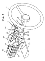
- Figs. 3-5 illustrate the function of the knee bar 20.
- Fig. 3 shows the steering wheel suspension system according to the present invention with the knee bar 20 in a starting position. It should be noted that the noses 26 (only one is shown) of the arm unit 22 are in contact with the corresponding protrusions 50 (only one is shown) of the box construction 5.
- the following scenario is played out during a collision.
- the driver's body is moved forwardly in the vehicle as a result of the laws of inertia.
- the knees of the driver thus come into contact with the pillow 21 of the knee bar 20 so that the driver's forward movement in the vehicles results in that the pillow 21 is moved forwardly in the vehicle, that is from the first moment shown in Fig. 3 to the position shown in Fig. 4 .
- the noses 26 and the associated contact surfaces 27 will affect the protrusions 30 so that the protrusions 30 are shifted in the length direction L of the steering wheel suspension system towards the link 23.
- the protrusions are shifted relative to its associated contact surface 27 so that the shifting is done in the direction away from the corresponding nose 26.
- the above-described shifting of the protrusions 30 also results in that the box construction, including the steering wheel axle 1 and the steering wheel shaft 3 are shifted in the same direction.
- Fig. 5 shows that there is an additional forward shifting of the pillow 21 of the knee bar 20 that is from the position shown in Fig. 4 to the position shown in Fig. 5 .
- This shifting also occurs because the driver moves forwardly during the collision and that the knees of the driver also are shifted forwardly and cause the shifting of the pillow 21 from the position shown in Fig. 4 to the position shown in Fig. 5 .
- Fig. 6 an alternative embodiment of the steering wheel suspension system according to the present invention is shown.
- the basic difference compared to the embodiment according to Figs. 1-5 is that the pillow 21 is replaced by a transverse rod 121 that runs between the first arm portions 24.
- a first drawbar 135 extends from the transverse rod to an energy-storing device 136 and a second drawbar 137 extends between the energy-storing device 136 and a stationary part of the suspension system according to the present invention.
- the second drawbar 137 may be fastened directly to the chassis of the vehicle.
- the energy-storing device 136 may be a pyrotechnic element, e.g. an element that is part of a belt tensioning device.
- the energy-storing device may also be in the shape of a spring that stores energy, said energy subsequently being released.
- the energy-storing device may be released electrically simultaneously as the airbag is released, i.e. the sensor system of the airbag is used.
- the arm unit 22 When the energy-storing device is released the arm unit 22 will be rotated in a similar way as described above in connection with the embodiment according to Figs. 1-5 .
- the steering wheel axle may be provided with or connected to an energy-absorbing member i.e. when the upper body of the driver comes into contact with the steering wheel 7, the steering wheel and the steering wheel axle 1 will move forwardly when the driver exerts a certain force onto the steering wheel 7.
- the steering wheel suspension system of the present invention has a member for adjusting the steering wheel axle 1/steering wheel 7 in the axial direction and in the height direction.
- a member for adjusting the steering wheel axle 1/steering wheel 7 in the axial direction and in the height direction is possible to omit such adjustment members of the steering wheel suspension system.
- the above described steering wheel suspension system includes a pillow 21 that the knees of the driver come into contact with during a collision.
- a pillow 21 that the knees of the driver come into contact with during a collision.
- an inflatable collision pillow into the pillow 21. This means that the inflatable collision pillow encounters the knees of the driver at an earlier stage.
- the contact surfaces 27 shown in the figures according to the above-described embodiment of steering wheel suspension system of the present invention are substantially plane.
- a different shaped of the stop surfaces could be used.
- concave stop surfaces could be mentioned.
Landscapes
- Engineering & Computer Science (AREA)
- Mechanical Engineering (AREA)
- Chemical & Material Sciences (AREA)
- Combustion & Propulsion (AREA)
- Transportation (AREA)
- Steering-Linkage Mechanisms And Four-Wheel Steering (AREA)
- Vehicle Body Suspensions (AREA)
Claims (9)
- Lenkradaufhängungssystem für ein Fahrzeug, um das Risiko von Verletzungen des Fahrzeugfahrers zu reduzieren, wenn das Fahrzeug einer Kollision ausgesetzt ist, wobei das System eine Lenkradachse (1), einen Lenkradschaft (3), in welchem die Lenkradachse (1) drehbar gehalten wird, ein Lenkrad (7), welches an einem Ende der Lenkradachse (1) angeordnet ist und ein Aktivierungselement (22) welches Teil einer Knieleiste (20) ist, beinhaltet, dadurch gekennzeichnet, dass eine Kastenkonstruktion (5) fest an dem Lenkradschaft (3) befestigt ist, wobei eine Konsole (9) die Kastenkonstruktion (5) trägt, dass die Kastenkonstruktion (5) relativ zu der Konsole (9) in einer Längsrichtung (L) des Lenkradaufhängungssystems verschiebbar ist, dass die Kastenkonstruktion (5) ein Antriebselement (30) hat, dass das Aktivierungselement (22) drehbar an der Konsole (9) aufgehängt ist, dass das Aktivierungselement (22) einen Armabschnitt (26, 27), welcher auf das Antriebselement (30) wirkt, wenn das Aktivierungselement (22) in eine Schwingbewegung gebracht wird, durch Verschieben der Knieleiste (20), wobei die Verschiebung durch die Knie des Fahrers bewirkt wird, wenn das Fahrzeug einer Kollision ausgesetzt ist, beinhaltet.
- Lenkradaufhängungssystem nach Anspruch 1, dadurch gekennzeichnet, dass das Aktivierungselement (22) eine Armeinheit bildet, die über eine Verbindung (23) drehbar an der Konsole (9) aufgehängt ist.
- Lenkradsteuerungssystem nach Anspruch 1, dadurch gekennzeichnet, dass die Knieleiste (20) ein Kissen (21) beinhaltet.
- Lenkradaufhängungssystem nach Anspruch 1, dadurch gekennzeichnet, dass zwischen der Kastenkonstruktion (5) und der Konsole (9) eine Reibungskupplung ausgebildet ist.
- Lenkradaufhängungssystem nach Anspruch 1, dadurch gekennzeichnet, dass das Antriebselement (30) Vorsprünge auf der Kastenkonstruktion bildet, die mit Kontaktflächen (27) auf den Armabschnitten (25) zusammenarbeiten.
- Lenkradaufhängungssystem nach Anspruch 1, dadurch gekennzeichnet, dass die Lenkradachse (1) mit einem Energieabsorptionselement verbunden ist.
- Lenkradaufhängungssystem nach Anspruch 1, dadurch gekennzeichnet, dass die wechselseitige Position der Kastenkonstruktion (5) und der Konsole (9) in der Längsrichtung (L) und der Höhenrichtung (H) des Lenkradaufhängungssystems aufgrund einer Anordnung von Schlitzen (8, 10, 14) und Leisten (11, 16) einstellbar ist.
- Lenkradaufhängungssystem nach Anspruch 1, dadurch gekennzeichnet, dass die Schlitze (8, 10, 14) in der Kastenkonstruktion (5) angeordnet sind und dass die Leisten (11, 16) in Verbindung mit der Konsole (9) stehen.
- Lenkradaufhängungssystem nach Anspruch 1, dadurch gekennzeichnet, dass eine Energiespeichervorrichtung (136) mit dem Aktivierungselement (22) verbunden ist, wobei die Energiespeichervorrichtung (136) mit einem stationären Teil des Lenkradaufhängungssystems verbunden ist.
Applications Claiming Priority (2)
| Application Number | Priority Date | Filing Date | Title |
|---|---|---|---|
| SE0600895A SE0600895L (de) | 2006-04-25 | ||
| PCT/SE2007/000391 WO2007123467A1 (en) | 2006-04-25 | 2007-04-24 | Steering wheel suspension system |
Publications (3)
| Publication Number | Publication Date |
|---|---|
| EP2015977A1 EP2015977A1 (de) | 2009-01-21 |
| EP2015977A4 EP2015977A4 (de) | 2012-08-01 |
| EP2015977B1 true EP2015977B1 (de) | 2014-01-15 |
Family
ID=38618774
Family Applications (1)
| Application Number | Title | Priority Date | Filing Date |
|---|---|---|---|
| EP07748056.4A Not-in-force EP2015977B1 (de) | 2006-04-25 | 2007-04-24 | Lenkradaufhängungssystem |
Country Status (3)
| Country | Link |
|---|---|
| US (1) | US7425020B2 (de) |
| EP (1) | EP2015977B1 (de) |
| WO (1) | WO2007123467A1 (de) |
Families Citing this family (1)
| Publication number | Priority date | Publication date | Assignee | Title |
|---|---|---|---|---|
| CN116236277B (zh) * | 2023-03-16 | 2025-08-05 | 南昌华安众辉健康科技股份有限公司 | 一种柔性臂装置及具有该柔性臂的医疗器械 |
Family Cites Families (17)
| Publication number | Priority date | Publication date | Assignee | Title |
|---|---|---|---|---|
| EP0000252B1 (de) | 1977-06-29 | 1982-02-03 | Beecham Group Plc | Peptiden, Verfahren zu dessen Herstellung und denen enthaltende pharmazeutische Präparate |
| DE3623414A1 (de) * | 1986-07-11 | 1988-01-14 | Porsche Ag | Haltevorrichtung fuer eine lenksaeule eines kraftfahrzeugs |
| JPH07110610B2 (ja) * | 1987-12-18 | 1995-11-29 | 本田技研工業株式会社 | 車両のステアリングコラム固定部構造 |
| DE4328446A1 (de) * | 1993-08-24 | 1995-03-02 | Pars Passive Rueckhaltesysteme | Sicherheitseinrichtung für die Fahrgastzelle einer Kraftfahrzeug-Karosserie |
| US5476283A (en) * | 1994-02-02 | 1995-12-19 | Mascotech Automotive Systems, Inc. | Selectively deployable vehicle knee restraint |
| EP0757946A3 (de) * | 1995-08-05 | 1998-03-04 | Volkswagen Aktiengesellschaft | Sicherheitseinrichtung, insbesondere für den Fahrer eines Kraftfahrzeuges |
| SE507008C2 (sv) | 1996-09-16 | 1998-03-16 | Lars Sundholm | Förfarande och system för minskande av personskada vid frontkollision |
| FR2805512B1 (fr) * | 2000-02-24 | 2002-05-03 | Nacam | Dispositif de guidage lineaire d'une colonne de direction |
| WO2001064483A1 (de) * | 2000-02-29 | 2001-09-07 | Krupp Presta Ag | Sicherheitseinrichtung für ein fahrzeug mit einer lenkung und sicherheitsverfahren |
| US6491322B1 (en) * | 2000-03-21 | 2002-12-10 | Lear Corporation | Energy absorbing bracket assembly for vehicle knee bolster |
| US7311333B2 (en) * | 2002-07-10 | 2007-12-25 | Nsk, Ltd. | Vehicle shock absorption type steering column device |
| JP4056834B2 (ja) * | 2002-09-10 | 2008-03-05 | 豊田合成株式会社 | 運転者保護装置 |
| US7128342B2 (en) * | 2003-01-31 | 2006-10-31 | Delphi Technologies, Inc. | Linear tracking knee bolster assembly |
| US7063354B2 (en) * | 2003-01-31 | 2006-06-20 | Delphi Technologies, Inc. | Linear tracking column module |
| US7185918B2 (en) * | 2003-01-31 | 2007-03-06 | Delphi Technologies, Inc. | Linear tracking column module with pedal assembly |
| KR100530030B1 (ko) * | 2003-06-16 | 2005-11-21 | 현대모비스 주식회사 | 자동차용 틸트 스티어링 장치 |
| JP2005186735A (ja) * | 2003-12-25 | 2005-07-14 | Toyota Motor Corp | ステアリングシステム |
-
2007
- 2007-03-05 US US11/681,835 patent/US7425020B2/en not_active Expired - Fee Related
- 2007-04-24 EP EP07748056.4A patent/EP2015977B1/de not_active Not-in-force
- 2007-04-24 WO PCT/SE2007/000391 patent/WO2007123467A1/en not_active Ceased
Also Published As
| Publication number | Publication date |
|---|---|
| US20070246926A1 (en) | 2007-10-25 |
| WO2007123467A1 (en) | 2007-11-01 |
| US7425020B2 (en) | 2008-09-16 |
| EP2015977A4 (de) | 2012-08-01 |
| EP2015977A1 (de) | 2009-01-21 |
Similar Documents
| Publication | Publication Date | Title |
|---|---|---|
| KR100861844B1 (ko) | 무릎 보호대 및 승무원 하지 보호 방법 및 무릎 보호대를구비한 자동차 | |
| US5346255A (en) | Steering column with a safety element for a motor vehicle equipped with an inflatable air bag in the steering wheel | |
| US6938720B2 (en) | Steering input devices for steer-by-wire systems | |
| JP3936571B2 (ja) | 車両用の折り畳み可能なステアリングコラム組立体 | |
| JP4531203B2 (ja) | 車両用の調整可能なステアリングコラムの締め付け機構 | |
| SE507008C2 (sv) | Förfarande och system för minskande av personskada vid frontkollision | |
| EP1221404B1 (de) | Ein Lenkradsystem | |
| US6435555B1 (en) | Collapsible steering column and method | |
| JP2009090856A (ja) | ステアリング装置 | |
| EP2015977B1 (de) | Lenkradaufhängungssystem | |
| JP2007533538A (ja) | 自動車用の安全ステアリングコラム | |
| KR100201728B1 (ko) | 에너지 흡수체계 | |
| JP2002193116A (ja) | ステアリング装置 | |
| EP1566323B1 (de) | Lenksäulenmodul mit linearer Bewegungsbahn | |
| EP0463501B1 (de) | Kraftdämpfende und zusammenschiebbare Lenksäulehalter | |
| GB2293143A (en) | Vehicle steering control device | |
| KR20080093274A (ko) | 충격 흡수 부재가 구비된 조향컬럼 | |
| EP1169198B1 (de) | Sicherheitseinrichtung für ein lenkrad | |
| JP2975229B2 (ja) | 車輛のステアリング装置 | |
| KR101136264B1 (ko) | 와이어 플레이트를 구비한 자동차의 충격 흡수식 조향컬럼 | |
| KR100440281B1 (ko) | 자동차의 조향장치 | |
| KR100368860B1 (ko) | 자동차의 조향축 마운팅 브라켓 | |
| JP4617916B2 (ja) | ステアリング装置の支持構造 | |
| JP2005007947A (ja) | 衝撃吸収式ステアリングコラム装置 | |
| JP2010208460A (ja) | ステアリングコラム装置 |
Legal Events
| Date | Code | Title | Description |
|---|---|---|---|
| PUAI | Public reference made under article 153(3) epc to a published international application that has entered the european phase |
Free format text: ORIGINAL CODE: 0009012 |
|
| 17P | Request for examination filed |
Effective date: 20081124 |
|
| AK | Designated contracting states |
Kind code of ref document: A1 Designated state(s): AT BE BG CH CY CZ DE DK EE ES FI FR GB GR HU IE IS IT LI LT LU LV MC MT NL PL PT RO SE SI SK TR |
|
| AX | Request for extension of the european patent |
Extension state: AL BA HR MK RS |
|
| RIN1 | Information on inventor provided before grant (corrected) |
Inventor name: LINDQUIST, MATS |
|
| RIC1 | Information provided on ipc code assigned before grant |
Ipc: B60R 21/05 20060101ALI20090224BHEP Ipc: B60R 21/00 20060101ALI20090224BHEP Ipc: B62D 1/187 20060101AFI20090224BHEP Ipc: B62D 1/19 20060101ALI20090224BHEP |
|
| A4 | Supplementary search report drawn up and despatched |
Effective date: 20120703 |
|
| RIC1 | Information provided on ipc code assigned before grant |
Ipc: B62D 1/19 20060101ALI20120627BHEP Ipc: B60R 21/00 20060101ALI20120627BHEP Ipc: B60R 21/05 20060101ALI20120627BHEP Ipc: B62D 1/187 20060101AFI20120627BHEP |
|
| DAX | Request for extension of the european patent (deleted) | ||
| GRAP | Despatch of communication of intention to grant a patent |
Free format text: ORIGINAL CODE: EPIDOSNIGR1 |
|
| INTG | Intention to grant announced |
Effective date: 20130612 |
|
| GRAS | Grant fee paid |
Free format text: ORIGINAL CODE: EPIDOSNIGR3 |
|
| GRAA | (expected) grant |
Free format text: ORIGINAL CODE: 0009210 |
|
| AK | Designated contracting states |
Kind code of ref document: B1 Designated state(s): AT BE BG CH CY CZ DE DK EE ES FI FR GB GR HU IE IS IT LI LT LU LV MC MT NL PL PT RO SE SI SK TR |
|
| REG | Reference to a national code |
Ref country code: GB Ref legal event code: FG4D Ref country code: CH Ref legal event code: EP |
|
| REG | Reference to a national code |
Ref country code: AT Ref legal event code: REF Ref document number: 649687 Country of ref document: AT Kind code of ref document: T Effective date: 20140215 |
|
| REG | Reference to a national code |
Ref country code: IE Ref legal event code: FG4D |
|
| REG | Reference to a national code |
Ref country code: DE Ref legal event code: R096 Ref document number: 602007034796 Country of ref document: DE Effective date: 20140227 |
|
| REG | Reference to a national code |
Ref country code: NL Ref legal event code: T3 |
|
| REG | Reference to a national code |
Ref country code: AT Ref legal event code: MK05 Ref document number: 649687 Country of ref document: AT Kind code of ref document: T Effective date: 20140115 |
|
| REG | Reference to a national code |
Ref country code: LT Ref legal event code: MG4D |
|
| PG25 | Lapsed in a contracting state [announced via postgrant information from national office to epo] |
Ref country code: LT Free format text: LAPSE BECAUSE OF FAILURE TO SUBMIT A TRANSLATION OF THE DESCRIPTION OR TO PAY THE FEE WITHIN THE PRESCRIBED TIME-LIMIT Effective date: 20140115 Ref country code: IS Free format text: LAPSE BECAUSE OF FAILURE TO SUBMIT A TRANSLATION OF THE DESCRIPTION OR TO PAY THE FEE WITHIN THE PRESCRIBED TIME-LIMIT Effective date: 20140515 |
|
| PG25 | Lapsed in a contracting state [announced via postgrant information from national office to epo] |
Ref country code: FI Free format text: LAPSE BECAUSE OF FAILURE TO SUBMIT A TRANSLATION OF THE DESCRIPTION OR TO PAY THE FEE WITHIN THE PRESCRIBED TIME-LIMIT Effective date: 20140115 Ref country code: AT Free format text: LAPSE BECAUSE OF FAILURE TO SUBMIT A TRANSLATION OF THE DESCRIPTION OR TO PAY THE FEE WITHIN THE PRESCRIBED TIME-LIMIT Effective date: 20140115 Ref country code: ES Free format text: LAPSE BECAUSE OF FAILURE TO SUBMIT A TRANSLATION OF THE DESCRIPTION OR TO PAY THE FEE WITHIN THE PRESCRIBED TIME-LIMIT Effective date: 20140115 Ref country code: SE Free format text: LAPSE BECAUSE OF FAILURE TO SUBMIT A TRANSLATION OF THE DESCRIPTION OR TO PAY THE FEE WITHIN THE PRESCRIBED TIME-LIMIT Effective date: 20140115 Ref country code: PT Free format text: LAPSE BECAUSE OF FAILURE TO SUBMIT A TRANSLATION OF THE DESCRIPTION OR TO PAY THE FEE WITHIN THE PRESCRIBED TIME-LIMIT Effective date: 20140515 Ref country code: CY Free format text: LAPSE BECAUSE OF FAILURE TO SUBMIT A TRANSLATION OF THE DESCRIPTION OR TO PAY THE FEE WITHIN THE PRESCRIBED TIME-LIMIT Effective date: 20140115 |
|
| PG25 | Lapsed in a contracting state [announced via postgrant information from national office to epo] |
Ref country code: LV Free format text: LAPSE BECAUSE OF FAILURE TO SUBMIT A TRANSLATION OF THE DESCRIPTION OR TO PAY THE FEE WITHIN THE PRESCRIBED TIME-LIMIT Effective date: 20140115 |
|
| REG | Reference to a national code |
Ref country code: DE Ref legal event code: R097 Ref document number: 602007034796 Country of ref document: DE |
|
| PG25 | Lapsed in a contracting state [announced via postgrant information from national office to epo] |
Ref country code: DK Free format text: LAPSE BECAUSE OF FAILURE TO SUBMIT A TRANSLATION OF THE DESCRIPTION OR TO PAY THE FEE WITHIN THE PRESCRIBED TIME-LIMIT Effective date: 20140115 Ref country code: RO Free format text: LAPSE BECAUSE OF FAILURE TO SUBMIT A TRANSLATION OF THE DESCRIPTION OR TO PAY THE FEE WITHIN THE PRESCRIBED TIME-LIMIT Effective date: 20140115 Ref country code: EE Free format text: LAPSE BECAUSE OF FAILURE TO SUBMIT A TRANSLATION OF THE DESCRIPTION OR TO PAY THE FEE WITHIN THE PRESCRIBED TIME-LIMIT Effective date: 20140115 |
|
| PLBE | No opposition filed within time limit |
Free format text: ORIGINAL CODE: 0009261 |
|
| STAA | Information on the status of an ep patent application or granted ep patent |
Free format text: STATUS: NO OPPOSITION FILED WITHIN TIME LIMIT |
|
| PG25 | Lapsed in a contracting state [announced via postgrant information from national office to epo] |
Ref country code: LU Free format text: LAPSE BECAUSE OF FAILURE TO SUBMIT A TRANSLATION OF THE DESCRIPTION OR TO PAY THE FEE WITHIN THE PRESCRIBED TIME-LIMIT Effective date: 20140424 Ref country code: MC Free format text: LAPSE BECAUSE OF FAILURE TO SUBMIT A TRANSLATION OF THE DESCRIPTION OR TO PAY THE FEE WITHIN THE PRESCRIBED TIME-LIMIT Effective date: 20140115 Ref country code: PL Free format text: LAPSE BECAUSE OF FAILURE TO SUBMIT A TRANSLATION OF THE DESCRIPTION OR TO PAY THE FEE WITHIN THE PRESCRIBED TIME-LIMIT Effective date: 20140115 Ref country code: SK Free format text: LAPSE BECAUSE OF FAILURE TO SUBMIT A TRANSLATION OF THE DESCRIPTION OR TO PAY THE FEE WITHIN THE PRESCRIBED TIME-LIMIT Effective date: 20140115 |
|
| REG | Reference to a national code |
Ref country code: CH Ref legal event code: PL |
|
| 26N | No opposition filed |
Effective date: 20141016 |
|
| REG | Reference to a national code |
Ref country code: IE Ref legal event code: MM4A |
|
| PG25 | Lapsed in a contracting state [announced via postgrant information from national office to epo] |
Ref country code: CH Free format text: LAPSE BECAUSE OF NON-PAYMENT OF DUE FEES Effective date: 20140430 Ref country code: LI Free format text: LAPSE BECAUSE OF NON-PAYMENT OF DUE FEES Effective date: 20140430 |
|
| REG | Reference to a national code |
Ref country code: DE Ref legal event code: R097 Ref document number: 602007034796 Country of ref document: DE Effective date: 20141016 |
|
| PG25 | Lapsed in a contracting state [announced via postgrant information from national office to epo] |
Ref country code: IE Free format text: LAPSE BECAUSE OF NON-PAYMENT OF DUE FEES Effective date: 20140424 |
|
| PG25 | Lapsed in a contracting state [announced via postgrant information from national office to epo] |
Ref country code: SI Free format text: LAPSE BECAUSE OF FAILURE TO SUBMIT A TRANSLATION OF THE DESCRIPTION OR TO PAY THE FEE WITHIN THE PRESCRIBED TIME-LIMIT Effective date: 20140115 |
|
| PG25 | Lapsed in a contracting state [announced via postgrant information from national office to epo] |
Ref country code: MT Free format text: LAPSE BECAUSE OF FAILURE TO SUBMIT A TRANSLATION OF THE DESCRIPTION OR TO PAY THE FEE WITHIN THE PRESCRIBED TIME-LIMIT Effective date: 20140115 |
|
| REG | Reference to a national code |
Ref country code: FR Ref legal event code: PLFP Year of fee payment: 10 |
|
| PG25 | Lapsed in a contracting state [announced via postgrant information from national office to epo] |
Ref country code: BG Free format text: LAPSE BECAUSE OF FAILURE TO SUBMIT A TRANSLATION OF THE DESCRIPTION OR TO PAY THE FEE WITHIN THE PRESCRIBED TIME-LIMIT Effective date: 20140115 |
|
| PG25 | Lapsed in a contracting state [announced via postgrant information from national office to epo] |
Ref country code: GR Free format text: LAPSE BECAUSE OF FAILURE TO SUBMIT A TRANSLATION OF THE DESCRIPTION OR TO PAY THE FEE WITHIN THE PRESCRIBED TIME-LIMIT Effective date: 20140416 Ref country code: IT Free format text: LAPSE BECAUSE OF FAILURE TO SUBMIT A TRANSLATION OF THE DESCRIPTION OR TO PAY THE FEE WITHIN THE PRESCRIBED TIME-LIMIT Effective date: 20140115 |
|
| PGFP | Annual fee paid to national office [announced via postgrant information from national office to epo] |
Ref country code: NL Payment date: 20160420 Year of fee payment: 10 |
|
| PG25 | Lapsed in a contracting state [announced via postgrant information from national office to epo] |
Ref country code: TR Free format text: LAPSE BECAUSE OF FAILURE TO SUBMIT A TRANSLATION OF THE DESCRIPTION OR TO PAY THE FEE WITHIN THE PRESCRIBED TIME-LIMIT Effective date: 20140115 Ref country code: HU Free format text: LAPSE BECAUSE OF FAILURE TO SUBMIT A TRANSLATION OF THE DESCRIPTION OR TO PAY THE FEE WITHIN THE PRESCRIBED TIME-LIMIT; INVALID AB INITIO Effective date: 20070424 |
|
| PGFP | Annual fee paid to national office [announced via postgrant information from national office to epo] |
Ref country code: CZ Payment date: 20160422 Year of fee payment: 10 Ref country code: GB Payment date: 20160421 Year of fee payment: 10 |
|
| PGFP | Annual fee paid to national office [announced via postgrant information from national office to epo] |
Ref country code: FR Payment date: 20160421 Year of fee payment: 10 Ref country code: BE Payment date: 20160420 Year of fee payment: 10 |
|
| REG | Reference to a national code |
Ref country code: NL Ref legal event code: MM Effective date: 20170501 |
|
| GBPC | Gb: european patent ceased through non-payment of renewal fee |
Effective date: 20170424 |
|
| REG | Reference to a national code |
Ref country code: FR Ref legal event code: ST Effective date: 20171229 |
|
| PG25 | Lapsed in a contracting state [announced via postgrant information from national office to epo] |
Ref country code: CZ Free format text: LAPSE BECAUSE OF NON-PAYMENT OF DUE FEES Effective date: 20170424 Ref country code: NL Free format text: LAPSE BECAUSE OF NON-PAYMENT OF DUE FEES Effective date: 20170501 Ref country code: FR Free format text: LAPSE BECAUSE OF NON-PAYMENT OF DUE FEES Effective date: 20170502 |
|
| PG25 | Lapsed in a contracting state [announced via postgrant information from national office to epo] |
Ref country code: GB Free format text: LAPSE BECAUSE OF NON-PAYMENT OF DUE FEES Effective date: 20170424 |
|
| REG | Reference to a national code |
Ref country code: BE Ref legal event code: MM Effective date: 20170430 |
|
| PG25 | Lapsed in a contracting state [announced via postgrant information from national office to epo] |
Ref country code: BE Free format text: LAPSE BECAUSE OF NON-PAYMENT OF DUE FEES Effective date: 20170430 |
|
| PGFP | Annual fee paid to national office [announced via postgrant information from national office to epo] |
Ref country code: DE Payment date: 20180420 Year of fee payment: 12 |
|
| REG | Reference to a national code |
Ref country code: DE Ref legal event code: R119 Ref document number: 602007034796 Country of ref document: DE |
|
| PG25 | Lapsed in a contracting state [announced via postgrant information from national office to epo] |
Ref country code: DE Free format text: LAPSE BECAUSE OF NON-PAYMENT OF DUE FEES Effective date: 20191101 |