EP1566323B1 - Lenksäulenmodul mit linearer Bewegungsbahn - Google Patents
Lenksäulenmodul mit linearer Bewegungsbahn Download PDFInfo
- Publication number
- EP1566323B1 EP1566323B1 EP05075130A EP05075130A EP1566323B1 EP 1566323 B1 EP1566323 B1 EP 1566323B1 EP 05075130 A EP05075130 A EP 05075130A EP 05075130 A EP05075130 A EP 05075130A EP 1566323 B1 EP1566323 B1 EP 1566323B1
- Authority
- EP
- European Patent Office
- Prior art keywords
- steering
- assembly
- bracket
- tubes
- bolster
- Prior art date
- Legal status (The legal status is an assumption and is not a legal conclusion. Google has not performed a legal analysis and makes no representation as to the accuracy of the status listed.)
- Expired - Lifetime
Links
- 230000007246 mechanism Effects 0.000 claims abstract description 56
- 230000004044 response Effects 0.000 claims abstract description 18
- 210000003127 knee Anatomy 0.000 claims description 23
- 239000006096 absorbing agent Substances 0.000 claims description 6
- 230000000712 assembly Effects 0.000 description 5
- 238000000429 assembly Methods 0.000 description 5
- 238000005452 bending Methods 0.000 description 3
- 230000000977 initiatory effect Effects 0.000 description 2
- 230000002452 interceptive effect Effects 0.000 description 1
- 239000000463 material Substances 0.000 description 1
- 230000004048 modification Effects 0.000 description 1
- 238000012986 modification Methods 0.000 description 1
- 230000002093 peripheral effect Effects 0.000 description 1
Images




Classifications
-
- B—PERFORMING OPERATIONS; TRANSPORTING
- B60—VEHICLES IN GENERAL
- B60R—VEHICLES, VEHICLE FITTINGS, OR VEHICLE PARTS, NOT OTHERWISE PROVIDED FOR
- B60R21/00—Arrangements or fittings on vehicles for protecting or preventing injuries to occupants or pedestrians in case of accidents or other traffic risks
- B60R21/02—Occupant safety arrangements or fittings, e.g. crash pads
- B60R21/09—Control elements or operating handles movable from an operative to an out-of-the way position, e.g. pedals, switch knobs, window cranks
-
- B—PERFORMING OPERATIONS; TRANSPORTING
- B60—VEHICLES IN GENERAL
- B60T—VEHICLE BRAKE CONTROL SYSTEMS OR PARTS THEREOF; BRAKE CONTROL SYSTEMS OR PARTS THEREOF, IN GENERAL; ARRANGEMENT OF BRAKING ELEMENTS ON VEHICLES IN GENERAL; PORTABLE DEVICES FOR PREVENTING UNWANTED MOVEMENT OF VEHICLES; VEHICLE MODIFICATIONS TO FACILITATE COOLING OF BRAKES
- B60T7/00—Brake-action initiating means
- B60T7/02—Brake-action initiating means for personal initiation
- B60T7/04—Brake-action initiating means for personal initiation foot actuated
- B60T7/06—Disposition of pedal
- B60T7/065—Disposition of pedal with means to prevent injuries in case of collision
-
- B—PERFORMING OPERATIONS; TRANSPORTING
- B62—LAND VEHICLES FOR TRAVELLING OTHERWISE THAN ON RAILS
- B62D—MOTOR VEHICLES; TRAILERS
- B62D1/00—Steering controls, i.e. means for initiating a change of direction of the vehicle
- B62D1/02—Steering controls, i.e. means for initiating a change of direction of the vehicle vehicle-mounted
- B62D1/16—Steering columns
- B62D1/18—Steering columns yieldable or adjustable, e.g. tiltable
- B62D1/19—Steering columns yieldable or adjustable, e.g. tiltable incorporating energy-absorbing arrangements, e.g. by being yieldable or collapsible
- B62D1/195—Yieldable supports for the steering column
-
- B—PERFORMING OPERATIONS; TRANSPORTING
- B60—VEHICLES IN GENERAL
- B60R—VEHICLES, VEHICLE FITTINGS, OR VEHICLE PARTS, NOT OTHERWISE PROVIDED FOR
- B60R21/00—Arrangements or fittings on vehicles for protecting or preventing injuries to occupants or pedestrians in case of accidents or other traffic risks
- B60R2021/003—Arrangements or fittings on vehicles for protecting or preventing injuries to occupants or pedestrians in case of accidents or other traffic risks characterised by occupant or pedestian
- B60R2021/0039—Body parts of the occupant or pedestrian affected by the accident
- B60R2021/0051—Knees
Definitions
- the subject invention relates to a vehicle steering assembly having components movable in response to a crash condition.
- Collapsible steering column assemblies are well known in the art. Such assemblies typically include an energy-absorbing bracket or other support affixed to the body of a vehicle. Steering column components including, but not limited to a steering wheel and shaft are carried by the support. Should a collision occur in which a sufficiently large impact force is applied to the steering wheel, the steering column and wheel will collapse relative to the support and translate away from the driver of the vehicle.
- the collapse of the column typically takes place along the axis of the column, which may not correspond to a preferred collapse path, but for design limitations of the column.
- a collapsible steering assembly according to the preamble of claim 1 is known from US-A-6149196 .
- the present invention provides a collapsible steering assembly including a stationary guide bracket for attachment to a vehicle and a steering mechanism having a longitudinal axis.
- the assembly also features a steering mechanism support with a plurality of guide rods arranged about a common collapse axis.
- the guide rods not only interconnect the guide bracket and the steering mechanism, but also support the steering mechanism for axial movement along the collapse axis in response to application of a predetermined collapse force to the steering mechanism.
- the subject invention addresses the shortcomings of the prior assemblies through the provision of guide rods which interconnect the steering mechanism and associated guide bracket with a steering mechanism support, providing a modular, robust assembly which enables the steering mechanism to be supported during normal operation about one axis best suited for operation of the steering mechanism, while further supporting the assembly for collapse along a collapse path different than that of the steering mechanism axis.
- the steering mechanism moves simultaneously with the guide rods relative to the guide bracket to enable the steering mechanism to collapse along the collapse path other than that of the axis of the steering mechanism.
- the guide rods are preferably oriented independently of the axis of the steering mechanism to cause the steering mechanism to collapse in a direction corresponding to an ideal trajectory path of the upper torso of a driver in a collision to maximize the energy absorbed by the assembly.
- the guide rods are also preferably spaced from one another to provide a stable framework that resists any bending or deformation of the support structure during collapse.
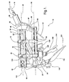
- a collapsible steering assembly is generally shown at 10 in Figure 1 .
- the assembly 10 includes a stationary guide bracket 12 for attachment to a vehicle and a steering mechanism 14 having a longitudinal steering mechanism axis 16.
- the assembly 10 also includes a steering mechanism support 17 with a plurality of guide rods 18 .
- the guide rods 18 are arranged about a common collapse axis 20 in non-parallel relationship to the steering mechanism axis 16 , and interconnect the guide bracket 12 and the steering mechanism 14 .
- the guide rods 18 also support the steering mechanism 14 for axial movement along the collapse axis 20 in response to application of a predetermined collapse force to the steering mechanism 14 .
- the steering mechanism 14 includes a steering shaft 22 .
- the shaft 22 extends coaxially with the steering mechanism axis 16 between upper and lower ends 24 and 26 .
- An upper bearing housing 28 and a rake bracket 30 are coaxially disposed about the shaft 22 adjacent the upper end 26.
- a lower bearing housing 32 is coaxially disposed about the shaft 22 adjacent the lower end 24 .
- the steering mechanism 14 shown in Figure 1 comprises a conventional steering column with a shaft 22, those skilled in the art will appreciate that the steering mechanism 14 used in the assembly 10 need not be limited to one utilizing a traditional column structure.
- the steering mechanism 14 may, for example, comprise a steer-by-wire system which may or may not include a mechanical steering linkage such as the shaft 22 .
- the assembly 10 also includes a plurality of steering shear elements 34 that interconnect the guide rods 18 and the guide bracket 12.
- the shear elements 34 operate to prevent movement of the steering mechanism 14 relative to the guide bracket 12 during normal useage of the assembly 10 , but are shearable in response to application of the predetermined collapse force on the steering mechanism 14 to enable the guide rods 18 and the steering mechanism 14 to move relative to the guide bracket 12 along the collapse axis 20.
- the guide bracket 12 supports the guide rods 18 in fixed relationship to one another, which in turn permits collective movement of the guide rods 18 relative to the guide bracket 12 in response to the predetermined collapse force on the steering mechanism 14.
- each guide rod 18 shown in Figure 1 is preferably straight and comprises a steering tube having a front end 36 and a rear end 38 .
- the steering tubes 18 of the present invention preferably include four tubes spaced from one another in a quadrangle.
- a front bracket 40 interconnects the front ends 36 of the steering tubes 18, and a rear bracket 42 supports the rear ends 38 of the steering tubes 18 and the steering mechanism 14 .
- the front and rear brackets 40 and 42 are spaced on opposite sides of the guide bracket 12, such that the guide bracket 12 is located along the steering tubes 18 between the front and rear brackets 40 and 42.
- a second plurality of steering shear elements 34 interconnect the rear bracket 42 and the steering tubes 18.
- the steering shear elements 34 normally prevent movement of the steering tubes 18 relative to the rear bracket 42 , but shear in response to application of the predetermined collapse force to the steering mechanism 14 f or allowing the steering tubes 18 to move through the rear bracket 42 in the same manner as the shear elements associated with the guide bracket 12.
- the rear ends 38 of the steering tubes 18 preferably extend through the rear bracket 42 .
- the front bracket 40 includes a central opening 44 and a peripheral edge 46 from which a collar 48 extends.
- the upper end 24 of the steering shaft 22 , the upper bearing housing 28 , and the rake bracket 30 extend through the opening 44 .
- the lower end 26 of the steering shaft 22 extends beyond the rear bracket 42, such that the front bracket 40 , guide bracket 12 and rear bracket 42 are spaced along the steering shaft 22 between the upper and lower ends 24 and 26.
- the rear bracket 42 includes at least one and preferably two connectors 50 for attachment to the vehicle.
- the guide bracket 12 likewise includes at least one and preferably two connectors 50 for attachment to the vehicle. Each connector 50 may be formed with a hole 51 or other feature for receiving a fastening bolt (not shown) to permit attachment to the vehicle.
- the assembly 10 also includes a knee bolster 52 for absorbing impact energy during a crash condition.
- a plurality of bolster guide rods 54 are arranged about a second collapse axis 55 and interconnect the guide bracket 12 and the knee bolster 52.
- the bolster guide rods 54 support the knee bolster 52 for axial movement along the second collapse axis 55 in response to application of a second predetermined collapse force to the knee bolster 52.
- a plurality of bolster shear elements 56 interconnect the bolster guide rods 54 and the guide bracket 12.
- the bolster shear elements 56 prevent the knee bolster 52 from moving relative to the guide bracket 12 during normal operation but are operative to shear in response to application of an applied collapse force to the knee bolster 52 sufficient to overcome the holding force of the shear elements 56, which in turn allows the bolster guide rods 54 and the knee bolster 52 to move relative to the guide bracket 12 in a collapse event.
- each of the bolster guide rods 54 may have any suitable shape
- each bolster guide rod 54 is preferably straight and comprises a tube having a front end 58 and a rear end 60. Any number of bolster guide rods, or bolster tubes, 54 may be utilized and arranged in any suitable configuration relative to the guide bracket 12.
- the bolster tubes 54 of the present invention preferably include four such tubes spaced from one another in a quadrangle.
- the guide bracket 12 includes an upper block 62 having bores 64 therethrough.
- the steering tubes 18 extend through the bores 64.
- the guide bracket 12 also includes a lower block 66 having bores 68 therethrough.
- the bolster tubes 54 extend through the bores 68 in the lower block 66 .
- the steering shear elements 34 and bolster shear elements 56 of the present invention preferably comprise bushings.
- Each bushing is interposed between one of the tubes 18 or 54 and one of either the guide bracket 12 or the rear bracket 42 and has a detent or other feature which maintains the tube 18 or 54 in a fixed position relative to the guide bracket 12 or the rear bracket 42 during normal operation.
- the bolster tubes 54 of the assembly 10 are disposed in at least one pair on either side of the steering tubes 18 .
- the bolster tubes 54 are also disposed parallel to the steering tubes 18 .
- Two pairs of bolster tubes 54 are disclosed, and each pair extends through the bores 68 in the lower block 66.
- the rear ends 60 of the bolster tubes 54 are supported by the rear bracket 42. Disposing the bolster tubes 54 outside the steering tubes 18 permits the knee bolster 52 to collapse without interfering with or otherwise initiating a simultaneous or subsequent collapse of the steering tubes 18 and steering mechanism 14 .
- the assembly 10 also includes an energy absorber system 70 for absorbing energy during movement of the steering mechanism 14 and knee bolster 52 relative to the guide bracket 12.
- the energy absorber system 70 includes a first anvil-strap device 72 interconnecting the steering tubes 18 and upper block 62.
- the first anvil-strap device 72 includes a release bracket 74 with bores 76 therethrough.
- the release bracket 74 is disposed in engagement with the upper block 62 .
- the steering tubes 18 extend through the bores 76 and are carried by the release bracket 74 in fixed relation to one another.
- the at least one and preferably two pair of plastically-deformable straps 78 with holes 80 therethrough are disposed in frictional and bending engagement with respective pairs of first and second anvils 82 and 84 .
- the straps 78 interconnect the release bracket 74 with the upper block 62 .
- Each pair of straps 78 includes a high-force strap 86 and a low-force strap 88 extending in parallel relation to one another from the release bracket 74 .
- Retaining pins 90 are disposed within the release bracket 74 .
- Each pin 90 extends through one of the holes 80 and interconnects the associated strap 86 or 88 with the release bracket 74 .
- the pins 90 may alternatively be disposed within the upper block 62 for securing the straps 86 and 88 with the upper block 62 .
- the first anvil-strap device 72 is a variable energy absorbing system that utilizes pairs of S-straps having variable widths.
- energy absorbing devices including but not limited to those which employ one or more M-straps, J-straps, other straps, wires, pyrotechnic or other actuating devices, or a combination thereof.
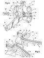
- the first anvil strap device 72 also includes actuating devices 100, which are disposed upon threaded bosses 102 that extend from the release bracket 74. Each actuating device 100 engages one of the pins 90 and selectively discharges for actuating movement of the pin 90 to a discharged position "P 1 ", such as that which is shown in Figure 4 . This alters the frictional and/or bending or resistance force generated by the strap 86 or 88 associated with the pin 90 as the straps 86 and 88 move across the anvils 82 and 84, respectively, to correspondingly alter the energy absorbing characteristics of the energy absorber system 70.
- Each pair of anvils 82 and 84 displaces a portion of the pair of straps 86 and 88 associated therewith and imposes a reaction force thereon to absorb energy as each pair of the straps 86 and 88 move past the respective pairs of anvils 82 and 84.
- the preferred actuating device 100 comprises an electrically activated pyrotechnic device.
- a control system such as that which is schematically depicted at 104 in Figure 4 is operatively connected to the devices 100 .
- the control system 104 monitors and detects variable components affected by the crash condition, determines the amount of energy to be absorbed, and transmits a signal corresponding to that amount to the actuating devices 100, which in turn actuates one or more of the devices 100 to modify the energy absorbing characteristics in accordance with the requirements of a particular crash event.
- the actuating devices 100 may initiate release of the low-force straps 88 to provide corresponding reduced energy absorbing characteristics of the system 104. Under still lesser crash conditions, the actuating devices 100 may respond to by initiating release of the high-force straps 86 to produce a correspondingly reduced energy absorbing characteristic of the system 104 .
- the energy absorber system 70 also includes a second anvil strap device 142 associated with the knee bolster 52.
- the second anvil strap device 142 includes many of the same components and functions in the same manner as the first anvil-strap device 72.
- the second anvil-strap device 142 includes a release bracket 144 which disposed against the lower block 66 during normal operation.
- the bolster tubes 54 are carried by the release bracket 144 in fixed relation to one another.
- a pair of energy absorbing straps 146 interconnect the release bracket 144 with the lower block 66.
- the high and low-force straps 148 and 150 of the pair 146 are secured by retaining pins 152 to the upper surface 154 of the release bracket 144 .
- the pins 152 will release one or both of the straps 148 and 150 upon being actuated in response to a signal transmitted from the control system 104 to absorb energy in response to application of the predetermined collapse force on the knee bolster 52 .
- any other suitable energy-absorbing device or devices may be used in place of the second anvil-strap device 142.
- a hinge assembly 92 extends from the release bracket 74.
- the hinge assembly 92 may be used for attaching an optional display screen or other control device (not shown) to the assembly 10.
- a lower bearing housing support 94 is also disposed on the release bracket 74.
- the support 94 has two arms that extend at an angle from the release bracket 74 to a connecting end 96 through which a hole 98 extends.
- a pivot pin (not shown) is disposed through the hole 98 and engages the lower bearing housing 94 for permitting pivotal movement of the steering mechanism 14 relative to the guide bracket 12.
- the assembly 10 also includes a pedal assembly, which is generally shown at 106 in Figure 7 .
- the pedal assembly 106 is pivotally connected to the rear bracket 42 for pivotal movement in response to movement of the steering tubes 18 relative to the rear bracket 42.
- the pedal assembly 106 includes a brake assembly 108 and a throttle assembly 110 .
- a mounting assembly 112 interconnects the brake and throttle assemblies 108 and 110 with the rear bracket 42 .
- the brake assembly 106 includes a brake pedal 114.
- a first bracket 116 interconnects the brake pedal 114 and the mounting bracket 112.
- the first bracket 116 includes a slot 118 .
- Adjustment fasteners 120 adjustably mount the brake pedal 114 in the slot 118 for permitting adjustment of the position of the brake pedal 114 relative to the first bracket 116 .
- the throttle assembly 110 includes a throttle pedal 122.
- a second bracket 124 interconnects the throttle pedal 122 and the mounting bracket 112.
- An adjustment fastener 128 adjustably mounts the throttle pedal 122 in the a slot 126 for adjusting the throttle pedal 122 relative to the second bracket 124 .
- the pedal assembly 106 also includes a hinge assembly 130 that interconnects the mounting bracket 112 and the rear bracket 42 and permits pivotal movement of the pedal assembly 106 .
- the hinge assembly 130 features a bifurcated bracket 132 that carries the mounting bracket 112 .
- the pedal assembly 106 also includes a motor 156 having drive cables 158 operatively connected to at least one pedal actuator 160 carried by the mounting assembly 112.
- the pedal actuator 160 selectively actuates movement of the brake and throttle assemblies 108 and 110 .
- the bifurcated bracket 132 includes a pair of screw bosses 162 through which screws extend (not shown) for securing the bracket 132 to the mounting assembly 112 .
- the pedal assembly 106 also includes a release mechanism 164 , which has a pair of pyrotechnic bosses 166 defining chambers 168.
- a pyrotechnic pin 170 is disposed within the rear bracket 42 and communicates with at least one of the chambers 168 .
- pyrotechnic devices 172 are disposed on the bosses 168. Actuating the devices 172 causes the pyrotechnic pin 170 to fire, which in turn causes the bifurcated bracket 132 to pivot away from the rear bracket 42.
Landscapes
- Engineering & Computer Science (AREA)
- Mechanical Engineering (AREA)
- Transportation (AREA)
- Chemical & Material Sciences (AREA)
- Combustion & Propulsion (AREA)
- Steering Controls (AREA)
Claims (23)
- Zusammenklappbare Lenkanordnung (10), die umfasst:einen feststehenden Führungsbügel (12) zum Anbringen an einem Fahrzeug,einen Lenkmechanismus (14) mit einer Lenkmechanismus-Längsachse (16), undeine Lenkmechanismus-Halterung (17) mit einer Vielzahl von Führungsstangen (18), die um eine gemeinsame Zusammenklappachse (20) herum in nicht paralleler Beziehung zu der Lenkmechanismusachse (16) angeordnet sind und den Führungsbügel (12) und den Lenkmechanismus (14) miteinander verbinden und den Lenkmechanismus (14) für eine axiale Bewegung entlang der Zusammenklappachse (20) in Ansprechen auf ein Aufbringen einer vorbestimmten Zusammenklappkraft auf den Lenkmechanismus (14) tragen,dadurch gekennzeichnet, dassder Führungsbügel (12) die Führungsstangen (18) in einer festen Beziehung zueinander trägt, undeine Vielzahl von Lenkungs-Scherelementen (34) die Führungsstangen (18) und den Führungsbügel (12) miteinander verbindet, um eine Bewegung des Lenkmechanismus (14) in Bezug auf den Führungsbügel (12) zu verhindern, und scherbar in Ansprechen auf ein Aufbringen der vorbestimmten Zusammenklappkraft auf den Lenkmechanismus (14) ist, um zuzulassen dass die Führungsstangen (18) und der Lenkmechanismus (14) sich in Bezug auf den Führungsbügel (12) bewegen.
- Anordnung nach Anspruch 1, wobei die Führungsstangen (18) gerade sind.
- Anordnung nach Anspruch 2, wobei jede der Führungsstangen (18) ein Lenkrohr umfasst, das sich von einem vorderen Ende (36) zu einem hinteren Ende (38) erstreckt.
- Anordnung nach Anspruch 3, wobei jedes der Lenkungs-Scherelemente (34) eine Buchse umfasst, die jedes Lenkrohr (18) umgibt und mit dem Führungsbügel (12) in Eingriff steht.
- Anordnung nach Anspruch 3, wobei der Führungsbügel (12) einen vorderen Bügel (40), der die vorderen Enden (36) der Lenkrohre (18) miteinander verbindet, und einen hinteren Bügel (42) umfasst, der die hinteren Enden (38) der Lenkrohre (18) und den Lenkmechanismus (14) trägt, wobei der vordere und der hintere Bügel (40) und (42) von dem Führungsbügel (12) beabstandet sind und sich an gegenüberliegenden Seiten davon befinden, wodurch der Führungsbügel (12) entlang der Lenkrohre (18) von und zwischen dem vorderen und dem hinteren Bügel (40) und (42) beabstandet ist.
- Anordnung nach Anspruch 5, wobei die Lenkrohre (18) vier Rohre umfassen, die voneinander in einem Viereck beabstandet sind.
- Anordnung nach Anspruch 5, wobei der hintere Bügel (42) einen Verbinder (50) zum Anbringen an dem Fahrzeug umfasst.
- Anordnung nach Anspruch 5, wobei die hinteren Enden (38) der Lenkrohre (18) sich durch den hinteren Bügel (42) hindurch erstrecken.
- Anordnung nach Anspruch 5, ferner umfassend ein Kniepolster (52) zum Absorbieren von Aufprallenergie während eines Unfallzustands, wobei eine Vielzahl von Polsterführungsstangen (54) um eine zweite Zusammenklappachse (55) herum angeordnet ist und den Führungsbügel (12) und das Kniepolster (52) miteinander verbindet und das Kniepolster (52) für eine axiale Bewegung entlang der zweiten Zusammenklappachse (55) in Ansprechen auf ein Aufbringen einer zweiten vorbestimmten Zusammenklappkraft auf das Kniepolster (52) trägt.
- Anordnung nach Anspruch 9, ferner umfassend eine Vielzahl von Polster-Scherelementen (56), die die Polsterführungsstangen (54) und den Führungsbügel (12) miteinander verbinden, um eine Bewegung des Kniepolsters (52) in Bezug auf den Führungsbügel (12) zu verhindern, und scherbar in Ansprechen auf ein Aufbringen der zweiten vorbestimmten Zusammenklappkraft auf das Kniepolster (52) sind, um zuzulassen, dass die Polsterführungsstangen (54) und das Kniepolster (52) sich in Bezug auf den Führungsbügel (12) bewegen.
- Anordnung nach Anspruch 10, wobei der Führungsbügel (12) die Polsterführungsstangen (54) in fester Beziehung zueinander trägt.
- Anordnung nach Anspruch 11, wobei die Polsterführungsstangen (54) gerade sind.
- Anordnung nach Anspruch 12, wobei jede der Polsterführungsstangen (54) ein Rohr umfasst.
- Anordnung nach Anspruch 13, wobei jedes der Polster-Scherelemente (56) eine Buchse umfasst, die jedes der Polsterrohre (54) umgibt und mit dem Führungsbügel (12) in Eingriff steht.
- Anordnung nach Anspruch 13, wobei die Polsterrohre (54) vier Rohre umfassen, die voneinander in einem Viereck beabstandet sind.
- Anordnung nach Anspruch 13, wobei die Polsterrohre (54) vordere und hintere Enden (58) und (60) aufweisen, wobei das Kniepolster (52) mit den vorderen Enden (58) der Polsterrohre (54) verbunden ist und der hintere Bügel (42) die hinteren Enden (60) der Polsterrohre (54) trägt,
wobei das Kniepolster (52) und der hintere Bügel (42) von dem Führungsbügel (12) beabstandet sind und sich an gegenüberliegenden Seiten davon befinden. - Anordnung nach Anspruch 16, wobei der Führungsbügel (12) einen oberen Block (62), der Bohrungen (64) dadurch aufweist, wobei die Lenkrohre (18) sich durch die Bohrungen (64) hindurch erstrecken, und einen unteren Block (66) umfasst, der Bohrungen (68) dadurch aufweist, wobei die Polsterrohre (54) sich durch die Bohrungen (68) in dem unteren Block (66) hindurch erstrecken.
- Anordnung nach Anspruch 17, umfassend eine zweite Vielzahl von Lenkungs-Scherelementen (34), die den hinteren Bügel (42) und die Lenkrohre (18) miteinander verbinden, um eine Bewegung der Lenkrohre (18) in Bezug auf den hinteren Bügel (42) zu verhindern, und scherbar in Ansprechen auf ein Aufbringen der vorbestimmten Zusammenklappkraft auf den Lenkmechanismus (14) sind, um zuzulassen, dass die Lenkrohre (18) sich durch den hinteren Bügel (42) hindurch bewegen.
- Anordnung nach Anspruch 13, umfassend ein Energieabsorbersystem (70) zum Absorbieren von Energie während einer Bewegung des Lenkmechanismus (14) bzw. des Kniepolsters (52) in Bezug auf den Führungsbügel (12).
- Anordnung nach Anspruch 19, wobei das Energieabsorbersystem (70) eine erste Amboss-Bandvorrichtung (72) umfasst, die die Lenkrohre (18) und den oberen Block (62) miteinander verbindet.
- Anordnung nach Anspruch 20, wobei die Polsterrohre (52) in zumindest einem Paar auf jeder Seite der Lenkrohre (18) angeordnet sind.
- Anordnung nach Anspruch 21, wobei die Polsterrohre (52) parallel zu den Lenkrohren (18) sind.
- Anordnung nach Anspruch 5, umfassend eine Pedalanordnung (106), die drehbar mit dem hinteren Bügel (42) verbunden ist, um eine Drehbewegung der Pedalanordnung (106) in Ansprechen auf eine Bewegung der Lenkrohre (18) in Bezug auf den hinteren Bügel (42) zuzulassen.
Applications Claiming Priority (2)
| Application Number | Priority Date | Filing Date | Title |
|---|---|---|---|
| US10/767,988 US7063354B2 (en) | 2003-01-31 | 2004-01-29 | Linear tracking column module |
| US767988 | 2004-01-29 |
Publications (3)
| Publication Number | Publication Date |
|---|---|
| EP1566323A2 EP1566323A2 (de) | 2005-08-24 |
| EP1566323A3 EP1566323A3 (de) | 2007-07-18 |
| EP1566323B1 true EP1566323B1 (de) | 2009-03-25 |
Family
ID=34711824
Family Applications (1)
| Application Number | Title | Priority Date | Filing Date |
|---|---|---|---|
| EP05075130A Expired - Lifetime EP1566323B1 (de) | 2004-01-29 | 2005-01-19 | Lenksäulenmodul mit linearer Bewegungsbahn |
Country Status (4)
| Country | Link |
|---|---|
| US (1) | US7063354B2 (de) |
| EP (1) | EP1566323B1 (de) |
| AT (1) | ATE426541T1 (de) |
| DE (1) | DE602005013439D1 (de) |
Families Citing this family (7)
| Publication number | Priority date | Publication date | Assignee | Title |
|---|---|---|---|---|
| US7128342B2 (en) * | 2003-01-31 | 2006-10-31 | Delphi Technologies, Inc. | Linear tracking knee bolster assembly |
| US7188866B2 (en) * | 2004-02-26 | 2007-03-13 | Delphi Technologies, Inc | Steering column assembly and method of fabricating the same |
| US7942446B2 (en) * | 2004-04-30 | 2011-05-17 | Nexteer (Beijing) Technology Co., Ltd. | Horizontal hybrid collapsing steering column |
| US7425020B2 (en) * | 2006-04-25 | 2008-09-16 | Mats Lindkvist | Steering wheel suspension system |
| JP5865805B2 (ja) * | 2012-09-05 | 2016-02-17 | Kyb株式会社 | ステアリング装置 |
| US10509120B2 (en) * | 2017-02-16 | 2019-12-17 | GM Global Technology Operations LLC | Lidar-radar relative pose calibration |
| US12583507B1 (en) * | 2024-11-21 | 2026-03-24 | Fca Us Llc | Decoupled driver controls module for vehicle |
Family Cites Families (34)
| Publication number | Priority date | Publication date | Assignee | Title |
|---|---|---|---|---|
| US3964578A (en) | 1975-08-27 | 1976-06-22 | General Motors Corporation | Energy absorber |
| US4738469A (en) | 1985-12-23 | 1988-04-19 | Mazda Motor Corporation | Structural arrangements for supporting steering devices |
| US4875385A (en) | 1986-08-18 | 1989-10-24 | Sitrin Gabriel M | Control pedal apparatus for a motor vehicle |
| US4949590A (en) | 1988-02-17 | 1990-08-21 | Automotive Products Plc | Hydraulic cylinder assembly |
| DE68909537T2 (de) | 1988-07-28 | 1994-02-03 | Fuji Kiko Kk | Positionierbare Pedaleinheit. |
| JP2521802B2 (ja) | 1988-12-28 | 1996-08-07 | 日産自動車株式会社 | 車両用ニ―プロテクタ構造 |
| US5086663A (en) | 1989-07-28 | 1992-02-11 | Fuji Kiko Company, Limited | Adjustable pedal |
| US5259646A (en) | 1992-03-20 | 1993-11-09 | Nissan Research & Development, Inc. | Multifunction one-piece bracket to support a steering column assemby and brake pedal support bracket in an automobile |
| US5181435A (en) | 1992-03-30 | 1993-01-26 | Chrysler Corp | Steering column guide assembly |
| JPH08113148A (ja) | 1994-10-19 | 1996-05-07 | Honda Motor Co Ltd | 車両のステアリングコラム支持構造 |
| DE19502226C1 (de) | 1995-01-25 | 1996-05-09 | Daimler Benz Ag | Aufprallschutz in einem Fahrzeuginnenraum, der über einen Biegeträger fahrzeugfest gelagert ist |
| DE19522398C1 (de) | 1995-06-23 | 1996-12-19 | Daimler Benz Ag | Sicherheitsanordnung im Fußraum eines Kraftwagens |
| SE507008C2 (sv) | 1996-09-16 | 1998-03-16 | Lars Sundholm | Förfarande och system för minskande av personskada vid frontkollision |
| SE507771C2 (sv) | 1996-11-21 | 1998-07-13 | Volvo Ab | Anordning och förfarande för skydd av åkande i fordon |
| SE510856C2 (sv) * | 1997-06-23 | 1999-06-28 | Volvo Ab | Kraftupptagande anordning för skydd av åkande i fordon |
| DE19747423C1 (de) * | 1997-10-27 | 1999-04-29 | Bsrs Restraint Syst Gmbh | Dynamische Knieschutzeinrichtung |
| DE19749970A1 (de) | 1997-11-05 | 1999-05-12 | Petri Ag | Insassen-Sicherheitsvorrichtung für die Fahrerseite eines Kraftfahrzeuges |
| SE518099C2 (sv) | 1997-11-21 | 2002-08-27 | Claes Johansson Automotive Ab | Inställbart pedalställ för ett fordon |
| JP3449206B2 (ja) | 1998-02-04 | 2003-09-22 | トヨタ自動車株式会社 | 車両用ペダル変位制御構造 |
| FR2781189B1 (fr) * | 1998-07-16 | 2000-09-15 | Allibert Ind | Dispositif de protection d'un conducteur de vehicule en cas de choc de ce dernier |
| US6474687B2 (en) | 1999-04-15 | 2002-11-05 | Visteon Global Technologies, Inc. | One-piece knee bolster |
| US6152488A (en) | 1999-06-16 | 2000-11-28 | Ford Global Technologies, Inc. | Steering column with variable collapse force |
| US6173625B1 (en) | 1999-12-14 | 2001-01-16 | Teleflex Incorporated | Adjustable multi-pedal assembly |
| FR2805512B1 (fr) | 2000-02-24 | 2002-05-03 | Nacam | Dispositif de guidage lineaire d'une colonne de direction |
| US6619155B2 (en) | 2000-05-15 | 2003-09-16 | Grand Haven Stamped Products, Division Of Jsj Corporation | Adjustable pedal apparatus |
| GB2368561B (en) | 2000-11-01 | 2003-08-13 | Visteon Global Tech Inc | Motor vehicle steering column support assembly |
| US6581966B2 (en) | 2001-01-05 | 2003-06-24 | Ford Global Technologies, Inc. | Twin axis steering wheel system |
| JP2002308116A (ja) * | 2001-04-12 | 2002-10-23 | Nissan Motor Co Ltd | ステアリングコラム支持装置 |
| US6641166B2 (en) | 2001-05-25 | 2003-11-04 | General Motors Corporation | Extendable and retractable knee bolster system |
| US6609727B2 (en) | 2001-08-06 | 2003-08-26 | General Motors Corporation | Energy absorbing knee bolster assembly |
| KR100405559B1 (ko) | 2001-09-20 | 2003-11-14 | 현대자동차주식회사 | 자동차의 브레이크페달 밀림 방지구조 |
| US6685224B2 (en) | 2001-12-27 | 2004-02-03 | Daimlerchrysler Corporation | Tilt steering column |
| US7048306B2 (en) * | 2002-09-05 | 2006-05-23 | Delphi Technologies, Inc. | Steering column with tubular structure |
| US7188866B2 (en) * | 2004-02-26 | 2007-03-13 | Delphi Technologies, Inc | Steering column assembly and method of fabricating the same |
-
2004
- 2004-01-29 US US10/767,988 patent/US7063354B2/en not_active Expired - Fee Related
-
2005
- 2005-01-19 DE DE602005013439T patent/DE602005013439D1/de not_active Expired - Fee Related
- 2005-01-19 EP EP05075130A patent/EP1566323B1/de not_active Expired - Lifetime
- 2005-01-19 AT AT05075130T patent/ATE426541T1/de not_active IP Right Cessation
Also Published As
| Publication number | Publication date |
|---|---|
| US20040239090A1 (en) | 2004-12-02 |
| EP1566323A2 (de) | 2005-08-24 |
| ATE426541T1 (de) | 2009-04-15 |
| US7063354B2 (en) | 2006-06-20 |
| EP1566323A3 (de) | 2007-07-18 |
| DE602005013439D1 (de) | 2009-05-07 |
Similar Documents
| Publication | Publication Date | Title |
|---|---|---|
| US6595079B2 (en) | Collapsible steering column assembly for a vehicle | |
| EP0705754B1 (de) | Im Inneren zusammenschiebbare Lenksäule | |
| US5131286A (en) | Mechanism for absorbing energy transmitted through a vehicle steering column | |
| EP2151366B1 (de) | Lenksäule mit einem Stellorgan zum Anwenden einer resultierenden Kraft | |
| EP0479455A2 (de) | Lenksäuleneinrichtung | |
| US6290258B1 (en) | Collapsible steering column assembly for a vehicle | |
| US7185918B2 (en) | Linear tracking column module with pedal assembly | |
| US5738377A (en) | Shock absorbing plate for a vehicle steering wheel | |
| US20070228717A1 (en) | Steering column apparatus for vehicle | |
| US7384070B2 (en) | Shock absorbing steering column device for vehicle | |
| US7063354B2 (en) | Linear tracking column module | |
| CN1665711A (zh) | 电动转向装置 | |
| EP1559618B1 (de) | Kniepolster mit linearer Bewegungsbahn | |
| US5209135A (en) | Impact absorbing type steering column device | |
| JPH01254470A (ja) | ステアリング支持装置 | |
| KR100201728B1 (ko) | 에너지 흡수체계 | |
| CN111727148B (zh) | 用于机动车辆的转向柱 | |
| EP1555179A1 (de) | Einstellbare Pedaleinheit für Fahrzeuge | |
| JP2005343331A (ja) | 車両用ステアリング装置 | |
| JP4604425B2 (ja) | ステアリングコラムの取付構造 | |
| EP0463501A1 (de) | Kraftdämpfende und zusammenschiebbare Lenksäulehalter | |
| US6820899B2 (en) | Collapsible steering column assembly for a vehicle | |
| JP2002308117A (ja) | 衝撃吸収式ステアリング装置 | |
| JP2647175B2 (ja) | ステアリングチルト装置の操作レバー | |
| KR100231529B1 (ko) | 충격흡수용 조향장치의 취부구조 |
Legal Events
| Date | Code | Title | Description |
|---|---|---|---|
| PUAI | Public reference made under article 153(3) epc to a published international application that has entered the european phase |
Free format text: ORIGINAL CODE: 0009012 |
|
| AK | Designated contracting states |
Kind code of ref document: A2 Designated state(s): AT BE BG CH CY CZ DE DK EE ES FI FR GB GR HU IE IS IT LI LT LU MC NL PL PT RO SE SI SK TR |
|
| AX | Request for extension of the european patent |
Extension state: AL BA HR LV MK YU |
|
| PUAL | Search report despatched |
Free format text: ORIGINAL CODE: 0009013 |
|
| AK | Designated contracting states |
Kind code of ref document: A3 Designated state(s): AT BE BG CH CY CZ DE DK EE ES FI FR GB GR HU IE IS IT LI LT LU MC NL PL PT RO SE SI SK TR |
|
| AX | Request for extension of the european patent |
Extension state: AL BA HR LV MK YU |
|
| 17P | Request for examination filed |
Effective date: 20080118 |
|
| AKX | Designation fees paid |
Designated state(s): AT BE BG CH CY CZ DE DK EE ES FI FR GB GR HU IE IS IT LI LT LU MC NL PL PT RO SE SI SK TR |
|
| 17Q | First examination report despatched |
Effective date: 20080310 |
|
| GRAP | Despatch of communication of intention to grant a patent |
Free format text: ORIGINAL CODE: EPIDOSNIGR1 |
|
| GRAS | Grant fee paid |
Free format text: ORIGINAL CODE: EPIDOSNIGR3 |
|
| GRAA | (expected) grant |
Free format text: ORIGINAL CODE: 0009210 |
|
| AK | Designated contracting states |
Kind code of ref document: B1 Designated state(s): AT BE BG CH CY CZ DE DK EE ES FI FR GB GR HU IE IS IT LI LT LU MC NL PL PT RO SE SI SK TR |
|
| REG | Reference to a national code |
Ref country code: GB Ref legal event code: FG4D |
|
| REG | Reference to a national code |
Ref country code: CH Ref legal event code: EP |
|
| REG | Reference to a national code |
Ref country code: IE Ref legal event code: FG4D |
|
| REF | Corresponds to: |
Ref document number: 602005013439 Country of ref document: DE Date of ref document: 20090507 Kind code of ref document: P |
|
| PG25 | Lapsed in a contracting state [announced via postgrant information from national office to epo] |
Ref country code: SI Free format text: LAPSE BECAUSE OF FAILURE TO SUBMIT A TRANSLATION OF THE DESCRIPTION OR TO PAY THE FEE WITHIN THE PRESCRIBED TIME-LIMIT Effective date: 20090325 Ref country code: FI Free format text: LAPSE BECAUSE OF FAILURE TO SUBMIT A TRANSLATION OF THE DESCRIPTION OR TO PAY THE FEE WITHIN THE PRESCRIBED TIME-LIMIT Effective date: 20090325 Ref country code: LT Free format text: LAPSE BECAUSE OF FAILURE TO SUBMIT A TRANSLATION OF THE DESCRIPTION OR TO PAY THE FEE WITHIN THE PRESCRIBED TIME-LIMIT Effective date: 20090325 |
|
| PG25 | Lapsed in a contracting state [announced via postgrant information from national office to epo] |
Ref country code: PL Free format text: LAPSE BECAUSE OF FAILURE TO SUBMIT A TRANSLATION OF THE DESCRIPTION OR TO PAY THE FEE WITHIN THE PRESCRIBED TIME-LIMIT Effective date: 20090325 Ref country code: SE Free format text: LAPSE BECAUSE OF FAILURE TO SUBMIT A TRANSLATION OF THE DESCRIPTION OR TO PAY THE FEE WITHIN THE PRESCRIBED TIME-LIMIT Effective date: 20090625 Ref country code: AT Free format text: LAPSE BECAUSE OF FAILURE TO SUBMIT A TRANSLATION OF THE DESCRIPTION OR TO PAY THE FEE WITHIN THE PRESCRIBED TIME-LIMIT Effective date: 20090325 |
|
| NLV1 | Nl: lapsed or annulled due to failure to fulfill the requirements of art. 29p and 29m of the patents act | ||
| PG25 | Lapsed in a contracting state [announced via postgrant information from national office to epo] |
Ref country code: BE Free format text: LAPSE BECAUSE OF FAILURE TO SUBMIT A TRANSLATION OF THE DESCRIPTION OR TO PAY THE FEE WITHIN THE PRESCRIBED TIME-LIMIT Effective date: 20090325 |
|
| PG25 | Lapsed in a contracting state [announced via postgrant information from national office to epo] |
Ref country code: PT Free format text: LAPSE BECAUSE OF FAILURE TO SUBMIT A TRANSLATION OF THE DESCRIPTION OR TO PAY THE FEE WITHIN THE PRESCRIBED TIME-LIMIT Effective date: 20090901 Ref country code: CZ Free format text: LAPSE BECAUSE OF FAILURE TO SUBMIT A TRANSLATION OF THE DESCRIPTION OR TO PAY THE FEE WITHIN THE PRESCRIBED TIME-LIMIT Effective date: 20090325 Ref country code: EE Free format text: LAPSE BECAUSE OF FAILURE TO SUBMIT A TRANSLATION OF THE DESCRIPTION OR TO PAY THE FEE WITHIN THE PRESCRIBED TIME-LIMIT Effective date: 20090325 Ref country code: ES Free format text: LAPSE BECAUSE OF FAILURE TO SUBMIT A TRANSLATION OF THE DESCRIPTION OR TO PAY THE FEE WITHIN THE PRESCRIBED TIME-LIMIT Effective date: 20090706 |
|
| PG25 | Lapsed in a contracting state [announced via postgrant information from national office to epo] |
Ref country code: IS Free format text: LAPSE BECAUSE OF FAILURE TO SUBMIT A TRANSLATION OF THE DESCRIPTION OR TO PAY THE FEE WITHIN THE PRESCRIBED TIME-LIMIT Effective date: 20090725 Ref country code: NL Free format text: LAPSE BECAUSE OF FAILURE TO SUBMIT A TRANSLATION OF THE DESCRIPTION OR TO PAY THE FEE WITHIN THE PRESCRIBED TIME-LIMIT Effective date: 20090325 Ref country code: SK Free format text: LAPSE BECAUSE OF FAILURE TO SUBMIT A TRANSLATION OF THE DESCRIPTION OR TO PAY THE FEE WITHIN THE PRESCRIBED TIME-LIMIT Effective date: 20090325 Ref country code: RO Free format text: LAPSE BECAUSE OF FAILURE TO SUBMIT A TRANSLATION OF THE DESCRIPTION OR TO PAY THE FEE WITHIN THE PRESCRIBED TIME-LIMIT Effective date: 20090325 |
|
| PG25 | Lapsed in a contracting state [announced via postgrant information from national office to epo] |
Ref country code: DK Free format text: LAPSE BECAUSE OF FAILURE TO SUBMIT A TRANSLATION OF THE DESCRIPTION OR TO PAY THE FEE WITHIN THE PRESCRIBED TIME-LIMIT Effective date: 20090325 Ref country code: BG Free format text: LAPSE BECAUSE OF FAILURE TO SUBMIT A TRANSLATION OF THE DESCRIPTION OR TO PAY THE FEE WITHIN THE PRESCRIBED TIME-LIMIT Effective date: 20090625 |
|
| PLBE | No opposition filed within time limit |
Free format text: ORIGINAL CODE: 0009261 |
|
| STAA | Information on the status of an ep patent application or granted ep patent |
Free format text: STATUS: NO OPPOSITION FILED WITHIN TIME LIMIT |
|
| 26N | No opposition filed |
Effective date: 20091229 |
|
| REG | Reference to a national code |
Ref country code: FR Ref legal event code: TP |
|
| PG25 | Lapsed in a contracting state [announced via postgrant information from national office to epo] |
Ref country code: MC Free format text: LAPSE BECAUSE OF NON-PAYMENT OF DUE FEES Effective date: 20100131 |
|
| REG | Reference to a national code |
Ref country code: CH Ref legal event code: PL |
|
| GBPC | Gb: european patent ceased through non-payment of renewal fee |
Effective date: 20100119 |
|
| REG | Reference to a national code |
Ref country code: FR Ref legal event code: ST Effective date: 20100930 |
|
| PG25 | Lapsed in a contracting state [announced via postgrant information from national office to epo] |
Ref country code: GR Free format text: LAPSE BECAUSE OF FAILURE TO SUBMIT A TRANSLATION OF THE DESCRIPTION OR TO PAY THE FEE WITHIN THE PRESCRIBED TIME-LIMIT Effective date: 20090626 Ref country code: CH Free format text: LAPSE BECAUSE OF NON-PAYMENT OF DUE FEES Effective date: 20100131 Ref country code: LI Free format text: LAPSE BECAUSE OF NON-PAYMENT OF DUE FEES Effective date: 20100131 Ref country code: FR Free format text: LAPSE BECAUSE OF NON-PAYMENT OF DUE FEES Effective date: 20100201 |
|
| PG25 | Lapsed in a contracting state [announced via postgrant information from national office to epo] |
Ref country code: DE Free format text: LAPSE BECAUSE OF NON-PAYMENT OF DUE FEES Effective date: 20100803 |
|
| PG25 | Lapsed in a contracting state [announced via postgrant information from national office to epo] |
Ref country code: GB Free format text: LAPSE BECAUSE OF NON-PAYMENT OF DUE FEES Effective date: 20100119 |
|
| PG25 | Lapsed in a contracting state [announced via postgrant information from national office to epo] |
Ref country code: IE Free format text: LAPSE BECAUSE OF NON-PAYMENT OF DUE FEES Effective date: 20100119 |
|
| PG25 | Lapsed in a contracting state [announced via postgrant information from national office to epo] |
Ref country code: IT Free format text: LAPSE BECAUSE OF FAILURE TO SUBMIT A TRANSLATION OF THE DESCRIPTION OR TO PAY THE FEE WITHIN THE PRESCRIBED TIME-LIMIT Effective date: 20090325 |
|
| REG | Reference to a national code |
Ref country code: DE Ref legal event code: R081 Ref document number: 602005013439 Country of ref document: DE Owner name: GM GLOBAL TECHNOLOGY OPERATIONS, INC., US Free format text: FORMER OWNER: DELPHI TECHNOLOGIES, INC., TROY, US Effective date: 20110412 |
|
| PG25 | Lapsed in a contracting state [announced via postgrant information from national office to epo] |
Ref country code: CY Free format text: LAPSE BECAUSE OF FAILURE TO SUBMIT A TRANSLATION OF THE DESCRIPTION OR TO PAY THE FEE WITHIN THE PRESCRIBED TIME-LIMIT Effective date: 20090325 |
|
| PG25 | Lapsed in a contracting state [announced via postgrant information from national office to epo] |
Ref country code: LU Free format text: LAPSE BECAUSE OF NON-PAYMENT OF DUE FEES Effective date: 20100119 Ref country code: HU Free format text: LAPSE BECAUSE OF FAILURE TO SUBMIT A TRANSLATION OF THE DESCRIPTION OR TO PAY THE FEE WITHIN THE PRESCRIBED TIME-LIMIT Effective date: 20090926 |
|
| PG25 | Lapsed in a contracting state [announced via postgrant information from national office to epo] |
Ref country code: TR Free format text: LAPSE BECAUSE OF FAILURE TO SUBMIT A TRANSLATION OF THE DESCRIPTION OR TO PAY THE FEE WITHIN THE PRESCRIBED TIME-LIMIT Effective date: 20090325 |