EP2015672B1 - Fiber optic evaluation of tissue modification - Google Patents
Fiber optic evaluation of tissue modification Download PDFInfo
- Publication number
- EP2015672B1 EP2015672B1 EP07776150.0A EP07776150A EP2015672B1 EP 2015672 B1 EP2015672 B1 EP 2015672B1 EP 07776150 A EP07776150 A EP 07776150A EP 2015672 B1 EP2015672 B1 EP 2015672B1
- Authority
- EP
- European Patent Office
- Prior art keywords
- tissue
- ablation
- catheter
- fibers
- radiation
- Prior art date
- Legal status (The legal status is an assumption and is not a legal conclusion. Google has not performed a legal analysis and makes no representation as to the accuracy of the status listed.)
- Expired - Fee Related
Links
- 239000000835 fiber Substances 0.000 title claims description 39
- 238000011156 evaluation Methods 0.000 title claims description 8
- 238000012986 modification Methods 0.000 title description 14
- 230000004048 modification Effects 0.000 title description 14
- 238000002679 ablation Methods 0.000 claims description 52
- 238000001228 spectrum Methods 0.000 claims description 37
- 230000003595 spectral effect Effects 0.000 claims description 30
- 230000015572 biosynthetic process Effects 0.000 claims description 27
- 230000005855 radiation Effects 0.000 claims description 22
- 230000003287 optical effect Effects 0.000 claims description 21
- 238000005286 illumination Methods 0.000 claims description 19
- 238000011282 treatment Methods 0.000 claims description 18
- 239000000523 sample Substances 0.000 claims description 17
- 239000013307 optical fiber Substances 0.000 claims description 14
- 210000004369 blood Anatomy 0.000 claims description 8
- 239000008280 blood Substances 0.000 claims description 8
- XLYOFNOQVPJJNP-UHFFFAOYSA-N water Substances O XLYOFNOQVPJJNP-UHFFFAOYSA-N 0.000 claims description 5
- 230000010287 polarization Effects 0.000 claims description 4
- 238000013213 extrapolation Methods 0.000 claims 1
- 210000001519 tissue Anatomy 0.000 description 80
- 230000003902 lesion Effects 0.000 description 39
- 238000000034 method Methods 0.000 description 28
- 238000005755 formation reaction Methods 0.000 description 25
- 238000004458 analytical method Methods 0.000 description 16
- 238000013153 catheter ablation Methods 0.000 description 14
- 230000009286 beneficial effect Effects 0.000 description 12
- 210000002216 heart Anatomy 0.000 description 7
- 230000035515 penetration Effects 0.000 description 6
- 230000002708 enhancing effect Effects 0.000 description 5
- 210000005003 heart tissue Anatomy 0.000 description 5
- 238000011897 real-time detection Methods 0.000 description 5
- IJGRMHOSHXDMSA-UHFFFAOYSA-N Atomic nitrogen Chemical compound N#N IJGRMHOSHXDMSA-UHFFFAOYSA-N 0.000 description 4
- 230000006378 damage Effects 0.000 description 4
- 230000000694 effects Effects 0.000 description 4
- 230000005670 electromagnetic radiation Effects 0.000 description 4
- 238000005259 measurement Methods 0.000 description 4
- 238000010521 absorption reaction Methods 0.000 description 3
- 238000000149 argon plasma sintering Methods 0.000 description 3
- 230000001427 coherent effect Effects 0.000 description 3
- 238000001514 detection method Methods 0.000 description 3
- 238000011161 development Methods 0.000 description 3
- 230000004069 differentiation Effects 0.000 description 3
- 238000012544 monitoring process Methods 0.000 description 3
- 238000011002 quantification Methods 0.000 description 3
- 230000003321 amplification Effects 0.000 description 2
- 230000008859 change Effects 0.000 description 2
- 238000004891 communication Methods 0.000 description 2
- 230000002939 deleterious effect Effects 0.000 description 2
- 238000010586 diagram Methods 0.000 description 2
- 238000005516 engineering process Methods 0.000 description 2
- 238000001914 filtration Methods 0.000 description 2
- 238000003384 imaging method Methods 0.000 description 2
- 239000007788 liquid Substances 0.000 description 2
- 210000004185 liver Anatomy 0.000 description 2
- 239000003550 marker Substances 0.000 description 2
- 229910052757 nitrogen Inorganic materials 0.000 description 2
- 238000003199 nucleic acid amplification method Methods 0.000 description 2
- 210000002307 prostate Anatomy 0.000 description 2
- 230000004044 response Effects 0.000 description 2
- 238000004611 spectroscopical analysis Methods 0.000 description 2
- 238000001370 static light scattering Methods 0.000 description 2
- 238000002560 therapeutic procedure Methods 0.000 description 2
- 230000000007 visual effect Effects 0.000 description 2
- 206010002091 Anaesthesia Diseases 0.000 description 1
- 241000283690 Bos taurus Species 0.000 description 1
- 238000001919 Rayleigh scattering spectroscopy Methods 0.000 description 1
- 208000027418 Wounds and injury Diseases 0.000 description 1
- 230000002159 abnormal effect Effects 0.000 description 1
- 238000001949 anaesthesia Methods 0.000 description 1
- 230000037005 anaesthesia Effects 0.000 description 1
- 238000013459 approach Methods 0.000 description 1
- 238000003491 array Methods 0.000 description 1
- 206010003119 arrhythmia Diseases 0.000 description 1
- 210000001367 artery Anatomy 0.000 description 1
- 230000006399 behavior Effects 0.000 description 1
- 238000001574 biopsy Methods 0.000 description 1
- 206010061592 cardiac fibrillation Diseases 0.000 description 1
- 238000006243 chemical reaction Methods 0.000 description 1
- 230000015271 coagulation Effects 0.000 description 1
- 238000005345 coagulation Methods 0.000 description 1
- 239000000470 constituent Substances 0.000 description 1
- 230000008878 coupling Effects 0.000 description 1
- 238000010168 coupling process Methods 0.000 description 1
- 238000005859 coupling reaction Methods 0.000 description 1
- 238000005388 cross polarization Methods 0.000 description 1
- 230000008021 deposition Effects 0.000 description 1
- 239000002019 doping agent Substances 0.000 description 1
- 238000002674 endoscopic surgery Methods 0.000 description 1
- 230000007613 environmental effect Effects 0.000 description 1
- 238000002474 experimental method Methods 0.000 description 1
- 230000002600 fibrillogenic effect Effects 0.000 description 1
- 239000012530 fluid Substances 0.000 description 1
- 230000006870 function Effects 0.000 description 1
- 210000001035 gastrointestinal tract Anatomy 0.000 description 1
- 238000010438 heat treatment Methods 0.000 description 1
- 230000006872 improvement Effects 0.000 description 1
- 238000001727 in vivo Methods 0.000 description 1
- 239000004615 ingredient Substances 0.000 description 1
- 230000000977 initiatory effect Effects 0.000 description 1
- 208000014674 injury Diseases 0.000 description 1
- 238000007689 inspection Methods 0.000 description 1
- 238000011835 investigation Methods 0.000 description 1
- 210000004731 jugular vein Anatomy 0.000 description 1
- 238000013507 mapping Methods 0.000 description 1
- 239000000463 material Substances 0.000 description 1
- 230000007246 mechanism Effects 0.000 description 1
- 238000010606 normalization Methods 0.000 description 1
- 210000000056 organ Anatomy 0.000 description 1
- 230000037361 pathway Effects 0.000 description 1
- 230000007505 plaque formation Effects 0.000 description 1
- 238000002203 pretreatment Methods 0.000 description 1
- 230000008569 process Effects 0.000 description 1
- 238000012545 processing Methods 0.000 description 1
- 238000012797 qualification Methods 0.000 description 1
- 238000007674 radiofrequency ablation Methods 0.000 description 1
- 238000010223 real-time analysis Methods 0.000 description 1
- 231100000241 scar Toxicity 0.000 description 1
- 238000010183 spectrum analysis Methods 0.000 description 1
- 238000006467 substitution reaction Methods 0.000 description 1
- 230000008685 targeting Effects 0.000 description 1
- 238000012360 testing method Methods 0.000 description 1
- 230000000699 topical effect Effects 0.000 description 1
- 238000012546 transfer Methods 0.000 description 1
- 238000002604 ultrasonography Methods 0.000 description 1
- 229910052724 xenon Inorganic materials 0.000 description 1
- FHNFHKCVQCLJFQ-UHFFFAOYSA-N xenon atom Chemical compound [Xe] FHNFHKCVQCLJFQ-UHFFFAOYSA-N 0.000 description 1
Images


Classifications
-
- A—HUMAN NECESSITIES
- A61—MEDICAL OR VETERINARY SCIENCE; HYGIENE
- A61B—DIAGNOSIS; SURGERY; IDENTIFICATION
- A61B18/00—Surgical instruments, devices or methods for transferring non-mechanical forms of energy to or from the body
- A61B18/18—Surgical instruments, devices or methods for transferring non-mechanical forms of energy to or from the body by applying electromagnetic radiation, e.g. microwaves
- A61B18/20—Surgical instruments, devices or methods for transferring non-mechanical forms of energy to or from the body by applying electromagnetic radiation, e.g. microwaves using laser
- A61B18/22—Surgical instruments, devices or methods for transferring non-mechanical forms of energy to or from the body by applying electromagnetic radiation, e.g. microwaves using laser the beam being directed along or through a flexible conduit, e.g. an optical fibre; Couplings or hand-pieces therefor
-
- A—HUMAN NECESSITIES
- A61—MEDICAL OR VETERINARY SCIENCE; HYGIENE
- A61B—DIAGNOSIS; SURGERY; IDENTIFICATION
- A61B5/00—Measuring for diagnostic purposes; Identification of persons
- A61B5/0059—Measuring for diagnostic purposes; Identification of persons using light, e.g. diagnosis by transillumination, diascopy, fluorescence
- A61B5/0075—Measuring for diagnostic purposes; Identification of persons using light, e.g. diagnosis by transillumination, diascopy, fluorescence by spectroscopy, i.e. measuring spectra, e.g. Raman spectroscopy, infrared absorption spectroscopy
-
- A—HUMAN NECESSITIES
- A61—MEDICAL OR VETERINARY SCIENCE; HYGIENE
- A61B—DIAGNOSIS; SURGERY; IDENTIFICATION
- A61B5/00—Measuring for diagnostic purposes; Identification of persons
- A61B5/0059—Measuring for diagnostic purposes; Identification of persons using light, e.g. diagnosis by transillumination, diascopy, fluorescence
- A61B5/0082—Measuring for diagnostic purposes; Identification of persons using light, e.g. diagnosis by transillumination, diascopy, fluorescence adapted for particular medical purposes
- A61B5/0084—Measuring for diagnostic purposes; Identification of persons using light, e.g. diagnosis by transillumination, diascopy, fluorescence adapted for particular medical purposes for introduction into the body, e.g. by catheters
- A61B5/0086—Measuring for diagnostic purposes; Identification of persons using light, e.g. diagnosis by transillumination, diascopy, fluorescence adapted for particular medical purposes for introduction into the body, e.g. by catheters using infrared radiation
-
- A—HUMAN NECESSITIES
- A61—MEDICAL OR VETERINARY SCIENCE; HYGIENE
- A61B—DIAGNOSIS; SURGERY; IDENTIFICATION
- A61B17/00—Surgical instruments, devices or methods, e.g. tourniquets
- A61B2017/00017—Electrical control of surgical instruments
- A61B2017/00022—Sensing or detecting at the treatment site
- A61B2017/00057—Light
- A61B2017/00061—Light spectrum
Definitions
- the present invention relates to a medical diagnostic. More particularly, the present invention relates to optical interrogation configurations for investigating tissue modification in real-time during medical procedures.
- tissue destruction is typically achieved by subjecting the tissue to conditions outside the environmental profile needed to sustain the tissue alive.
- cardiac tissue ablation electrode catheters that can be inserted percutaneously under local anaesthesia into a femoral, brachial, subclavian, or internal jugular vein and positioned in the heart using techniques developed by those skilled in the field is performed to address cardiac arrhythmias, e.g., fibrillation.
- ablation systems include an ablation catheter or similar probe having an energy-emitting element.
- the energy-emitting element delivers energy forming a lesion in the targeted tissue.
- Typical elements include a microwave ablation element, a cryogenic ablation element, a thermal ablation element, a light-emitting ablation element, an ultrasound transducer, and/or a radio frequency ablation element.
- the ablation catheter may be adapted to form a variety of lesions such as linear lesions or a circumferential lesion.
- the element is connected to an energy source that can be varied to control the formation of the lesion.
- the majority of such systems utilizes the temperature of the ablation electrode to monitor tissue modification, such as lesion formation, and automatically adjusts power output to achieve a targeted electrode temperature.
- Knowledge of the electrode temperature at a particular ablation site is useful in determining whether the application of radiofrequency produced the desired ablation but it is not sufficient to accurately predict the dimensions of the lesion created, especially its depth.
- Spectral diagnostic may also be used for feedback control as disclosed in document US 5 304 173 .
- Thermal injury is the principal mechanism of tissue destruction during radiofrequency catheter ablation procedures. Elevation of catheter temperature can also result in non-desirable conditions, such as, coagulation of the blood.
- coagulation of the blood The development of a coagulum, which can represent a hazard to the patient (i.e., via stroke), results in a rapid increase in impedance which leads to a dramatic decrease in current density, thereby limiting further lesion growth.
- the ablation process can also cause undesirable charring of the tissue and can generate evaporate water in the blood and tissue leading to bursts of microbubbles (i.e., steam pops) during the ablation procedure, which are the result of deposition of energy at a faster than desired rate.
- the present invention is directed to such a need.
- the present invention is defined in claim 1.
- the present invention provides a tool that can be configured with optical fiber arrangements to provide real-time analysis of lesion formations, depth of penetration of a lesion, a cross-sectional area of a lesion in the tissue, recognition of charring, recognition of the formation of coagulum, differentiation of ablated tissue from healthy tissue, and/or recognition of evaporate water in the blood and tissue leading to steam pops.
- the present invention provides optical arrangements, capable of directing predetermined spectral radiation and capable of providing received and analyzed spectral information for the determination and quantification of normal or modified tissue.
- Applications include assessment of tissue parameters during cardiac ablation as well as assessment of tissue properties such as the formation of plaque, artery thickness, and scar tissue.
- the apparatus and methods, as disclosed herein, allow real-time qualification and quantification of tissue components, often during catheter ablation treatment of predetermined tissue components, such as the heart.
- tissue components such as the heart.
- lesion formation By utilizing the disclosed techniques of the present invention, lesion formation, depth of penetration of the lesion, cross-sectional area of the lesion in the tissue, recognition of charring, recognition of the formation of coagulum, differentiation of ablated tissue from healthy tissue, and recognition of evaporate water in the blood and tissue leading to microbubbles (i.e., steam pop formation) is beneficially enabled.
- Beneficial ablation catheter embodiments of the present invention are often configured with an optical conduit, i.e., optical fibers or fiber bundles disposed within the catheter from the proximal to about the distal end.
- the collection and detection system can include any of the optical means for collecting, e.g., refractive and reflective optics, filtering, e.g., notch filters, band-pass filters, edge filters, etc. and/or spectrally dispersing (e.g., using for example, predetermined spectrographs) received polarized and often unpolarized induced spectra so as to capture, and thus best quantify and qualify the spectral information of tissue components often undergoing modification.
- filtering e.g., notch filters, band-pass filters, edge filters, etc.
- spectrally dispersing e.g., using for example, predetermined spectrographs
- the detectors themselves often include charged coupled devices (CCDs), (e.g., front and back illuminated CCDs, liquid nitrogen cooled CCDs, on-chip amplification CCDs) but can also include photodiodes, photomultipliers, multi-channel spectral analyzers, two-dimensional array detectors, multi-array detectors, or any equivalent means to provide acquisition, often digitized acquisition, of one or more spectra.
- CCDs charged coupled devices
- photomultipliers multi-channel spectral analyzers
- two-dimensional array detectors two-dimensional array detectors
- multi-array detectors or any equivalent means to provide acquisition, often digitized acquisition, of one or more spectra.
- tissue modification such as, but not limited to, thermal or cryo tissue ablation
- an operator can obtain real-time feedback information about the site undergoing modification.
- intensity of NIR received elastic light scattered spectra between about 600 nm and about 1500 nm
- an operator can detect the onset as well as track the progress of tissue ablation.
- the relative intensity of the red-shifted component of the spectral profile increases as a function of the depth of ablation in time and deposited thermal energy.
- the changes in the spectral profile can be used to evaluate the depth of the lesion.
- an operator can use the slope of received spectra (i.e., defined by ratios of predetermined spectral bands of received spectra, such as the ratio of the 730 nm over the 910 nm part of the spectrum of received red-shifted spectra) for depth profiling using appropriate calibration methods known to those skilled in the art.
- Such a beneficial arrangement enables a user to extrapolate ablation depths past the point of directed illumination wavelength penetration depths.
- Other aspects of the received spectra can be utilized to monitor charring, coagulum, and/or steam pop formation due to observed characteristic changes as shown below in the present invention.
- operators or automatic software driven directions through closed loop operations can determined the exposure time and/ or terminate a procedure, or increase or decrease the energy delivered to the site as required for a desired effect (e.g., for greater lesion formation at a desired depth), or detect the formation of charring, coagulum, or the formation of steam pops or determine whether an application of ablation energy failed to reach a desired tissue modification.
- the present invention provides apparatus for rapid, in-vivo detection and evaluation of modified tissue components.
- the present invention provides elastic Near-infrared (NIR) light (i.e., elastic light scattered spectra between about 600 nm and about 1500 nm ) scattering inspection techniques and optical arrangements, often configured with ablation catheter embodiments, as known and utilized by those skilled in the art, to monitor in real-time, human tissue components undergoing tissue modification or for simple probe analysis.
- NIR Near-infrared
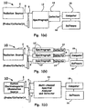
- Figs.1(a)-1(c) Such systems, designated generally by the reference numeral 10, is most often automated by an analysis means, such as software program 16, residing on a control analysis means 18 (e.g., a computer, firmware (ROM's, EPROM's) and integrated computational, storage, etc., circuit means, such as, but not limited to, large scale Integrated Circuits LSIC (LSIC), very large scale Integrated Circuits (VLSIC), and field-programmable gate arrays (FPGA's)), which is operably coupled to each component in system 10 by predetermined wireless and or hard communication lines (not shown) such as, USB or RS232 cables.
- a control analysis means 18 e.g., a computer, firmware (ROM's, EPROM's) and integrated computational, storage, etc.
- circuit means such as, but not limited to, large scale Integrated Circuits LSIC (LSIC), very large scale Integrated Circuits (VLSIC), and field-programmable gate arrays (FPGA's)
- LSIC large scale
- Such software means, firmware means, and other integrated circuit means can provide the filtering, storage and computational manipulations that is desired for the present application.
- Such communication lines can be constructed and arranged to allow for the exchange of information between analysis means 18 and the system components as shown in Figs.1(a)-1(c) to effect operation in a prescribed sequence at the direction of an operator or a predetermined set of programmed instructions to transfer spectral information to analysis means 16 for storage and immediate analysis during operational procedures.
- System 10 also includes an electromagnetic radiation source 2, as shown in Fig.1(a) and Fig.1(b) , for illumination of targeted tissue components.
- an electromagnetic radiation source 2 as shown in Fig.1(a) and Fig.1(b) , for illumination of targeted tissue components.
- a radiation source often includes emission wavelengths of greater than about 250, often a monochromatic laser light source operating at wavelengths of up to about 1500 nm, but most often from about 600 mm to about 970 nm in wavelengths, or from any non-coherent, broadband and/or a coherent source capable of being integrated into the present invention so as to delineate differences in absorption and scattering in human tissue components and to provide mean photon penetration depths of up to about 1 cm.
- such sources can include broadband sources (e.g., incandescent lamps, arc lamps, wide-band LEDs), narrow-band spectrally stable light emitting diodes (LEDs), narrow-band fluorescence sources, tunable optical sources (e.g., an optical parametric oscillator, dye lasers, or a Xenon source coupled with a computer controlled monochrometer), narrow-band stable lasers, tripled Nd:Yag systems, etc., all of which are capable of emitting predetermined filtered or otherwise spectral bands to interact with desired tissue components (not shown) so as to induce the desired NIR scattered spectral information.
- broadband sources e.g., incandescent lamps, arc lamps, wide-band LEDs
- LEDs narrow-band spectrally stable light emitting diodes
- tunable optical sources e.g., an optical parametric oscillator, dye lasers, or a Xenon source coupled with a computer controlled monochrometer
- narrow-band stable lasers tripled Nd
- Such radiation sources 2 can be configured with probe/catheter 4 via one or more operably coupled optical conduits, e.g., hollow waveguides, light guides, fiber(s) 8, etc., often large core optical fibers (i.e., multimode fibers) or fibers suitably designed with predetermined fiber indices and dopant profiles, tapered fiber ends and/or special cavity configurations (e.g., bend loss loops), etc. for maintaining polarization properties for predetermined applications, such as when desiring elastic differential light scattering information from a targeted tissue component.
- optical conduits e.g., hollow waveguides, light guides, fiber(s) 8, etc.
- core optical fibers i.e., multimode fibers
- fibers suitably designed with predetermined fiber indices and dopant profiles, tapered fiber ends and/or special cavity configurations (e.g., bend loss loops), etc.
- a custom electromagnetic radiation source(s) 3, as generically shown in Fig.1(c) can be configured along with or in substitution of a broadband source, as discussed above, to provide directed desired power levels of at least about 1 ⁇ W in one or more spectral bands/wavelengths of up to about 1500 nm, but most often from about 600 nm to about 970 nm in wavelengths, to about the distal end of the probe/catheter 4 via optical fiber(s) 8.
- Example custom electromagnetic radiation source(s) 3 can include, but are not limited to, one or more compact substantially coherent commercial diode lasers arranged with the desired spectral bandwidth, power levels, and geometries, for illumination of predetermined tissue components to induce NIR elastic scattered radiation between about 600 nm and about 1500 nm.
- optical fibers 9 e.g., one or more large core multimode fibers, polarization maintaining fibers, etc. are additionally configured to collect NIR elastic backscattered information about the distal end of probe/catheter 4 induced by light source 2 or light source 3, as shown in Figs. 1(a) -(c).
- optical fiber embodiments i.e., fibers shown by reference numerals 8 and 9, as shown in Figs.1(a) -(c)
- any probe such as, a hand-held probe for topical investigation of tissue modification
- fiber embodiments can be adapted with enhancing optical elements with respect to its ability to deliver and collect light to and from multiple locations in order to accommodate tissue interrogation of catheter positions from about a normal (i.e., 90 degrees) to about a parallel configuration (i.e., 90 degrees from the normal) with the interrogated tissue.
- enhancing optical elements can include, micro-lenses, mirrors, graded-index lenses, diffractive optical elements and other performance enhancing elements as known in the art.
- optical fiber configurations can be arranged with a probe, such as, for example, any of the rigid scopes utilized during endoscopic surgery and/or any of the flexible scopes generally reserved for diagnostic examinations and biopsies of tubular body cavities and/or structures, e.g., the upper intestinal tract being examined with a gastroscope.
- the optical configurations can be adapted with any of the treatment and/or diagnostic tools currently in the field, most often, however, the optical fiber embodiments entail coupling with any of the surgical ablation devices utilized for treatment of tissue components, such as, tissue components of the heart, prostate, and liver. Exemplary variations of such surgical ablation devices are described in U.S. Patent No. 6,522,930 and discussed in Application Serial No. 10/ 260,141 entitled "Fiber-Optic Evaluation of Cardiac Tissue Ablation".
- optical conduits e.g., optical fibers 9
- optical components such as, edge filters, band-pass filters, polarization filters, prisms, and/or notch filters, etc.
- Beneficial embodiments can simply include a single spectrograph 12, as shown in Fig.1(a) , or, one or more spectrographs 12', as shown in Fig. 1(b) , (three are shown for simplicity), such as when utilizing catheter embodiments that are arranged to provide information to predetermined spectrographs for angular detailed information of a treated site.
- Such spectrographs often include optical spectrum analyzers, such as, two-dimensional spectrum analyzers, single or single curved line spectrum analyzers, (i.e., a multi-channel spectrum analyzer 13 ), to provide, for example, screened cross-section spectroscopic information of a treated or a pre-treatment site.
- optical spectrum analyzers such as, two-dimensional spectrum analyzers, single or single curved line spectrum analyzers, (i.e., a multi-channel spectrum analyzer 13 ), to provide, for example, screened cross-section spectroscopic information of a treated or a pre-treatment site.
- Fourier transform imaging spectrometers or other such devices to allow desired bands and/or polarized components of electromagnetic radiation from tissue components (not shown) can also be used to disperse and analyze received spectra.
- CCDs charged coupled devices
- the control system software 16 which can be beneficially automated, often includes a graphical user interface (GUI) configured from Visual Basic, MATLAB®, LabVIEW®, Visual C++, or any programmable language or specialized software programming environment to enable ease of operation when performing probe analysis, but more often, probe analysis during catheter ablation treatment of predetermined sites, such as, in predetermined sites of the heart.
- GUI graphical user interface
- LabVIEW® and/or MATLAB® in particular, is specifically tailored to the development of instrument control applications and facilitates rapid user interface creation and is particularly beneficial as an application to be utilized as a specialized software embodiment when desired.
- the received one or more spectra are then captured and stored by analysis means 18 for storage and immediate analysis during operational procedures, which then allows an operator to effect desired changes to, for example, the time of the treatment procedure.
- Fig. 2(a) shows a basic catheter embodiment of the present invention, generally designated as reference numeral 20, for real time monitoring of, for example, tissue ablation during treatment of predetermined organs, such as, but not limited to, the liver, prostate, and heart (e.g., a cardiac ablation catheter (e.g., steerable or guidewire catheter embodiments) inserted using, for example, a transseptal or retrograde aortic approach into predetermined sections of the heart to ablate, in some instances, accessory pathways.
- tissue ablation e.g., a coronary intervention catheter embodiments
- a transseptal or retrograde aortic approach into predetermined sections of the heart to ablate, in some instances, accessory pathways.
- optical configurations configured with such a catheter embodiment, or any of the arrangements disclosed herein can include commercial available optical elements, as known by those of ordinary skill in the art, or custom optical elements to deliver and/or collect predetermined light spectra from multiple locations about the distal end of such catheters.
- catheter 22 When utilized with ablation catheter embodiments, catheter 22 can be advanced into the targeted region, wherein a designed ablation element (not shown) of catheter 22 can be energized by means known in the art so as to form, for example, a lesion 23 in the surrounding tissue 28.
- catheter 22 When utilized in such a manner, catheter 22 often includes one or more illumination fibers 26 (one shown for simplicity) and one or more collection fibers 24 (again one shown for simplicity), as shown in Fig. 2(a) , running from about the distal end to the proximal end of catheter 22 so as to direct illumination wavelengths and collect desired radiation (as shown with directional arrows) respectively before, during or after application of ablation energy.
- predetermined illumination radiation of at least about 250 nm and up to about 1500 nm, but most often radiation from about 600 nm to about 970 nm, from one or more illumination fibers 26 configured about the distal end of catheter 22 is directed substantially along the same direction with catheter 22 (direction denoted by the letter Z and as shown with a directional arrow).
- tissue components such as normal tissue, non-normal tissue
- modified tissue components such as lesion 23 along an emission cone angle of illumination fiber(s) 26 or with illumination intensities as produced by adapted enhancing optical elements, such as, but not limited to, micro-lenses, mirrors, graded-index lenses, diffractive optical elements and other fiber performance enhancing elements as known in the art so as to induce NIR elastic scattered light in a backscattered geometry.
- adapted enhancing optical elements such as, but not limited to, micro-lenses, mirrors, graded-index lenses, diffractive optical elements and other fiber performance enhancing elements as known in the art so as to induce NIR elastic scattered light in a backscattered geometry.
- the one or more collection fibers 24 configured with catheter 22, receives a predetermined portion of the induced NIR elastic light scattered radiation from probed tissue at a receiving point (denoted as P' in Fig, 2(a) ), laterally removed from the emitting point of the one or more illumination fibers 26, (denoted as P as shown in Fig. 2(a) ).
- Such induced radiation is then directed by collection fiber(s) 24 to the spectral analysis and detector compartments as illustrated in Figs.1(a)- (c) as detailed above.
- the detectors transforms a photometric signal into an electrical signal.
- the electrical signal is captured by an electronic circuit (not shown) and is converted to a digital form with conventional analog/ digital converters as known and understood by those skilled in the art.
- the digital signal is then digitally pre-processed by digital signal processing residing in, for example, analysis means 18, as shown in Figs.1(a) -(c), and information is stored in memory.
- the information can be accessed by analysis means 18, or by one or one or more additional external computing devices (not shown) for further analysis, and presented to users through a graphic user interface via designed or commercial software, as disclosed herein.
- a surprising and unexpected result during ablation procedures is the characteristic changes in the received spectra, which enables the detection and determination of deleterious thermal effects (i.e., via intensity and/or characteristic changes in received spectra) resulting from charring, formation of steam pops, and coagulum.
- the operator can use such information to increase or decrease the energy delivered to the site so as to control the final depth of the lesion while preventing the observed thermal deleterious effects or terminate the ablation procedure altogether.
- example fibers i.e., fibers 24 and 26
- fibers 24 and 26 used for directing desired radiation components can also be coupled external (not shown) to catheter 22.
- fibers 24 and 26 are not directly targeting tissue 28 under catheter 22 and thus, such an arrangement is designed to record the presence on ablated tissue (e.g. lesion 23 ) as it expands in time outwards from the point of contact with ablation energizing element of catheter 22 and enables ease of operation by not having to overtly modify existing catheter embodiments.
- ablated tissue e.g. lesion 23
- Fig. 2(b) shows a variation of the catheter embodiment of Fig. 2(a) and is generally designated as reference numeral 20'.
- Such an arrangement again can include various probes, such as, but not limited to, a catheter 22 utilized for ablation procedures and modified according to the descriptions presented herein.
- one or more fibers 30 can again be used for collection while one or more fibers 26 may be used to deliver the illumination.
- one or more additional fibers 27 may be configured with catheter 22 to probe (i.e., illuminate) the tissue, such as a formed or a forming lesion 23 in the case where the catheter is used to ablate the tissue at an angle different than normal to the tissue's 28 surface.
- an additional collection fiber 31 not in contact with tissue 28 can also be added by modification to allow catheter embodiments, as shown by example in Fig. 2(b) , to probe the formation of coagulum, steam pops, and/or charring in the area surrounding the catheter that is not in direct contact with tissue 28 and enable evaluation of the orientation of the catheter with respect to the tissue surface.
- An advanced example arrangement involves a plurality of fibers alternated as illumination and/or collection of scattered light in a predetermined sequence so as to enable even more accurate assessment of the characteristic of ablation and the surrounding catheter environment (formation of coagulum, steam pops, charring, etc.).
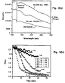
- Fig. 3(a) shows experimental data of about a two-fold increase (denoted by the directional arrow) in the intensity of the backscattering light during tissue ablation.
- a result is exemplified with spectra from normal tissue 32 exposed to ablation powers of 7W for 20 seconds 34 and subsequently 10W for 120 seconds 36.
- Such a change in intensity can be utilized, as one example, to detect steam pop formation (micro bubbles) resulting from heating of the surrounding tissue fluids.
- Fig. 3(a) also shows a changing slope of the spectral profile towards the longer wavelengths (i.e., at about the 900 run range) (denoted by the shorter directional arrow) due to the ablation exposure times and deposited thermal energy.
- Fig. 3(b) shows the slope of the spectrum of different sized lesions monitored during ablation lesion formation with different final depths.
- Fig. 3(b) shows the slope vs. time for 5 different ablations that resulted to lesions having depths of about 1 mm (40), 2mm (42), 4mm (44), 6mm (46), and 8 mm (48).
- the different rates by which the slope is changing depends on the power settings of the catheter. From such data, one can extract the rate of tissue ablation since the slope is related to the depth of the lesion. This can be particular important for deeper lesions where direct measurement of the depth using the fibers may be impossible.
- the measurement of the slope can provide accurate results for lesion depths of up to about 10 mm in human cardiac tissue.
- the rate of tissue ablation during the initial 6 mm one can extrapolate the ablation time needed to create lesions of any depth.
- Fig. 4 illustrates the substantially linear relationship between depth and spectral profile using as a marker, the slope of the profile after a linear fit of the profile between 730 nm and 900 nm.
- the ratio of the spectral intensity at 730 nm over that at 910 nm is plotted from predetermined spectra received from bovine heart tissue during an ablation procedure for a particular created lesion. Then additional slope values for different lesions created using different ablation times and power settings resulting in different lesion depths is added to the overall plot, as shown in Fig. 4 .
- Fig. 4 summarizes experimental results showing the depth of the ablated tissue and the corresponding slope of the accompanying spectral profile. These results clearly indicate an almost linear relationship between these two parameters for lesion depths up to about 6 mm.
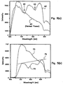
- Fig. 5(a) illustrates the real-time detection of coagulum formation during catheter ablation treatment from the characteristic changes in the detected spectral profile while Fig. 5(b) illustrates the real-time detection of charring during catheter ablation treatment.
- Fig. 5(a) shows a normal tissue spectrum 60 and the presence of two spectral dips 66 in a received spectrum 62, indicating the presence of two absorption peaks associated with the presence of coagulum.
- Fig. 5(b) shows a spectrum of normal tissue 70 and a subsequent spectrum 72 in the presence of charring. From the results of Fig.
- 5(b) charring tends to exhibit intensities of the scattered light at 730 nm that is lower to that at 910 nm (i.e., for the spectral calibration used during this experiment). This leads to an example value of the estimated slope of less than 1.
- the absolute values of the slope shown above are somewhat arbitrary. This comes from the fact that the recorded spectra have not been corrected for instrument response nor for the spectral profile of the white light used for illumination. Therefore, although all trends and qualitative behaviors describe above are valid, the absolute values of the slopes and the relative intensities of the spectra at different wavelengths need to be adjusted to take into account instrument response and spectrum of input illumination light
- the present invention utilizes primarily NIR light scattering to provide information about predetermined tissue properties prior to as well as during certain predetermined therapeutic procedures.
- the present disclosure can provide information with regards to lesion formation, depth of penetration of the lesion, cross-sectional area of the lesion in the tissue, recognition of charring, recognition of the formation of coagulum, differentiation of ablated tissue from healthy, diseased, and/or abnormal tissue, and recognition of evaporate water in the blood and tissue leading to microbubbles (i.e., steam pop formation) is beneficially enabled.
Landscapes
- Health & Medical Sciences (AREA)
- Life Sciences & Earth Sciences (AREA)
- Physics & Mathematics (AREA)
- Surgery (AREA)
- General Health & Medical Sciences (AREA)
- Public Health (AREA)
- Biomedical Technology (AREA)
- Heart & Thoracic Surgery (AREA)
- Medical Informatics (AREA)
- Molecular Biology (AREA)
- Veterinary Medicine (AREA)
- Animal Behavior & Ethology (AREA)
- Engineering & Computer Science (AREA)
- Biophysics (AREA)
- Pathology (AREA)
- Spectroscopy & Molecular Physics (AREA)
- Optics & Photonics (AREA)
- Electromagnetism (AREA)
- Nuclear Medicine, Radiotherapy & Molecular Imaging (AREA)
- Otolaryngology (AREA)
- Investigating Or Analysing Materials By Optical Means (AREA)
- Surgical Instruments (AREA)
- Laser Surgery Devices (AREA)
- Measurement Of The Respiration, Hearing Ability, Form, And Blood Characteristics Of Living Organisms (AREA)
Applications Claiming Priority (2)
| Application Number | Priority Date | Filing Date | Title |
|---|---|---|---|
| US11/414,009 US20060229515A1 (en) | 2004-11-17 | 2006-04-27 | Fiber optic evaluation of tissue modification |
| PCT/US2007/009989 WO2007127228A2 (en) | 2006-04-27 | 2007-04-24 | Fiber optic evaluation of tissue modification |
Publications (2)
| Publication Number | Publication Date |
|---|---|
| EP2015672A2 EP2015672A2 (en) | 2009-01-21 |
| EP2015672B1 true EP2015672B1 (en) | 2016-07-27 |
Family
ID=38578468
Family Applications (1)
| Application Number | Title | Priority Date | Filing Date |
|---|---|---|---|
| EP07776150.0A Expired - Fee Related EP2015672B1 (en) | 2006-04-27 | 2007-04-24 | Fiber optic evaluation of tissue modification |
Country Status (9)
| Country | Link |
|---|---|
| US (1) | US20060229515A1 (pt) |
| EP (1) | EP2015672B1 (pt) |
| JP (1) | JP5214589B2 (pt) |
| CN (1) | CN101563018B (pt) |
| BR (1) | BRPI0710871B8 (pt) |
| CA (1) | CA2650484C (pt) |
| MX (1) | MX2008013813A (pt) |
| RU (1) | RU2445041C2 (pt) |
| WO (1) | WO2007127228A2 (pt) |
Cited By (4)
| Publication number | Priority date | Publication date | Assignee | Title |
|---|---|---|---|---|
| US9649159B2 (en) | 2008-12-17 | 2017-05-16 | The Spectranetics Corporation | Eccentric balloon laser catheter |
| US9907614B2 (en) | 2014-10-29 | 2018-03-06 | The Spectranetics Corporation | Laser energy delivery devices including laser transmission detection systems and methods |
| US10492863B2 (en) | 2014-10-29 | 2019-12-03 | The Spectranetics Corporation | Laser energy delivery devices including laser transmission detection systems and methods |
| US10987167B2 (en) | 2008-11-05 | 2021-04-27 | The Spectranetics Corporation | Biasing laser catheter: monorail design |
Families Citing this family (54)
| Publication number | Priority date | Publication date | Assignee | Title |
|---|---|---|---|---|
| US10413188B2 (en) * | 2004-11-17 | 2019-09-17 | Lawrence Livermore National Security, Llc | Assessment of tissue or lesion depth using temporally resolved light scattering spectroscopy |
| US20060264760A1 (en) * | 2005-02-10 | 2006-11-23 | Board Of Regents, The University Of Texas System | Near infrared transrectal probes for prostate cancer detection and prognosis |
| US8628520B2 (en) | 2006-05-02 | 2014-01-14 | Biosense Webster, Inc. | Catheter with omni-directional optical lesion evaluation |
| US8147484B2 (en) * | 2006-10-23 | 2012-04-03 | Biosense Webster, Inc. | Apparatus and method for monitoring early formation of steam pop during ablation |
| AU2013200350B2 (en) * | 2006-10-23 | 2014-04-10 | Biosense Webster, Inc. | Apparatus and method for monitoring early formation of steam pop during ablation |
| US8986298B2 (en) | 2006-11-17 | 2015-03-24 | Biosense Webster, Inc. | Catheter with omni-directional optical tip having isolated optical paths |
| US8500730B2 (en) * | 2007-11-16 | 2013-08-06 | Biosense Webster, Inc. | Catheter with omni-directional optical tip having isolated optical paths |
| WO2010011820A2 (en) * | 2008-07-23 | 2010-01-28 | St. Jude Medical, Inc. | Ablation and monitoring system including a fiber optic imaging catheter and an optical coherence tomography system |
| GB0916727D0 (en) * | 2009-09-23 | 2009-11-04 | Univ St Andrews | Improvements in or relating to imaging |
| US8376955B2 (en) * | 2009-09-29 | 2013-02-19 | Covidien Lp | Spectroscopic method and system for assessing tissue temperature |
| WO2011111645A1 (ja) * | 2010-03-09 | 2011-09-15 | 学校法人慶應義塾 | レーザカテーテル出射部の血液焦げ付き防止システム |
| DE102010014703A1 (de) * | 2010-04-12 | 2011-10-13 | Mbr Optical Systems Gmbh & Co. Kg | Medizinisches Gerätesystem |
| US10314650B2 (en) * | 2010-06-16 | 2019-06-11 | Biosense Webster (Israel) Ltd. | Spectral sensing of ablation |
| US20140171806A1 (en) * | 2012-12-17 | 2014-06-19 | Biosense Webster (Israel), Ltd. | Optical lesion assessment |
| US11490957B2 (en) | 2010-06-16 | 2022-11-08 | Biosense Webster (Israel) Ltd. | Spectral sensing of ablation |
| US8159665B2 (en) * | 2010-07-21 | 2012-04-17 | Bwt Property, Inc. | Apparatus and methods for fluorescence subtraction in Raman spectroscopy |
| CN103153174B (zh) | 2010-10-14 | 2015-08-19 | 皇家飞利浦电子股份有限公司 | 用于确定对象的性质的性质确定装置 |
| US8812079B2 (en) * | 2010-12-22 | 2014-08-19 | Biosense Webster (Israel), Ltd. | Compensation for magnetic disturbance due to fluoroscope |
| JP5807386B2 (ja) * | 2011-05-24 | 2015-11-10 | 住友電気工業株式会社 | 生体組織変性装置 |
| JP6198731B2 (ja) * | 2011-07-11 | 2017-09-20 | コーニンクレッカ フィリップス エヌ ヴェKoninklijke Philips N.V. | エネルギー適用計画装置 |
| CN104066368B (zh) | 2011-09-22 | 2017-02-22 | 乔治华盛顿大学 | 用于使经消融组织可视化的系统和方法 |
| EP2757933B1 (en) | 2011-09-22 | 2019-02-06 | The George Washington University | Systems for visualizing ablated tissue |
| WO2013067595A1 (en) * | 2011-11-10 | 2013-05-16 | The University Of Western Australia | A method for characterising a mechanical property of a material |
| WO2013111053A1 (en) * | 2012-01-27 | 2013-08-01 | Koninklijke Philips N.V. | An apparatus for optical analysis of an associated tissue |
| CN102641152B (zh) * | 2012-05-22 | 2014-03-05 | 上海理工大学 | 基于fpga的高频电刀发生器 |
| US10499984B2 (en) | 2012-07-18 | 2019-12-10 | Bernard Boon Chye Lim | Apparatus and method for assessing tissue treatment |
| US9526426B1 (en) | 2012-07-18 | 2016-12-27 | Bernard Boon Chye Lim | Apparatus and method for assessing tissue composition |
| US10881459B2 (en) | 2012-07-18 | 2021-01-05 | Bernard Boon Chye Lim | Apparatus and method for assessing tissue treatment |
| US20140171936A1 (en) * | 2012-12-17 | 2014-06-19 | Biosense Webster (Israel) Ltd. | Irrigated catheter tip with temperature sensor and optic fiber arrays |
| WO2014168734A1 (en) | 2013-03-15 | 2014-10-16 | Cedars-Sinai Medical Center | Time-resolved laser-induced fluorescence spectroscopy systems and uses thereof |
| US20160235303A1 (en) * | 2013-10-11 | 2016-08-18 | The Trustees Of Columbia University In The City Of New York | System, method and computer-accessible medium for characterization of tissue |
| US11096584B2 (en) | 2013-11-14 | 2021-08-24 | The George Washington University | Systems and methods for determining lesion depth using fluorescence imaging |
| US20150141847A1 (en) * | 2013-11-20 | 2015-05-21 | The George Washington University | Systems and methods for hyperspectral analysis of cardiac tissue |
| US9675416B2 (en) * | 2014-04-28 | 2017-06-13 | Biosense Webster (Israel) Ltd. | Prevention of steam pops during ablation |
| US20160081555A1 (en) * | 2014-09-18 | 2016-03-24 | Biosense Webster (Israel) Ltd. | Multi-range optical sensing |
| WO2016073476A1 (en) | 2014-11-03 | 2016-05-12 | The George Washington University | Systems and methods for lesion assessment |
| CN107427213B (zh) | 2014-11-03 | 2021-04-16 | 460医学股份有限公司 | 用于接触质量的评估的系统和方法 |
| AU2015268674A1 (en) * | 2014-12-29 | 2016-07-14 | Biosense Webster (Israel) Ltd. | Spectral sensing of ablation |
| CN107743376B (zh) * | 2015-06-10 | 2021-06-25 | 波士顿科学医学有限公司 | 通过评估响应于激发辐射的光致发光的身体物质检测 |
| US10779904B2 (en) | 2015-07-19 | 2020-09-22 | 460Medical, Inc. | Systems and methods for lesion formation and assessment |
| US11154186B2 (en) | 2015-07-31 | 2021-10-26 | University Of Utah Research Foundation | Devices, systems, and methods for imaging and treating a selected tissue |
| US10278757B2 (en) | 2015-10-20 | 2019-05-07 | Medtronic Cryocath Lp | Temperature and strain measurement technique during cryoablation |
| US10799280B2 (en) | 2015-10-22 | 2020-10-13 | Medtronic Cryocath Lp | Post ablation tissue analysis technique |
| CN105286993B (zh) * | 2015-11-24 | 2017-12-19 | 谭回 | 一种带检测仪的手术刀系统 |
| CN115561211A (zh) | 2016-04-01 | 2023-01-03 | 黑光外科公司 | 用于时间分辨荧光光谱法的系统、装置和方法 |
| JP7083833B2 (ja) | 2017-02-01 | 2022-06-13 | ユニバーシティ オブ ユタ リサーチ ファウンデーション | 心臓組織マッピングのための装置および方法 |
| CN109875674A (zh) * | 2017-12-06 | 2019-06-14 | 刘珈 | 肿瘤消融设备 |
| CN108294822A (zh) * | 2018-03-20 | 2018-07-20 | 江苏省肿瘤防治研究所(江苏省肿瘤医院) | 一种术中可辅助明确肿瘤切除范围的新型电凝刀 |
| EP3685781B8 (de) | 2019-01-24 | 2022-06-29 | Erbe Elektromedizin GmbH | Vorrichtung zur gewebekoagulation |
| JP2023510828A (ja) | 2020-01-13 | 2023-03-15 | メドルミクス,エセ.エレ. | アブレーションカテーテルを使用する病変の光学的な分析および予測のためのシステム |
| US11331142B2 (en) | 2020-01-13 | 2022-05-17 | Medlumics S.L. | Methods, devices, and support structures for assembling optical fibers in catheter tips |
| CN114929098A (zh) * | 2020-01-13 | 2022-08-19 | 梅德路米克斯有限公司 | 使用脉冲场或其它能量源的光学引导消融系统 |
| CA3179972A1 (en) * | 2020-04-14 | 2021-10-21 | The Regents Of The University Of California | Method and system for selective spectral illumination for optical image guided surgery |
| CN113440250B (zh) * | 2021-05-28 | 2023-01-06 | 南京航空航天大学 | 基于组织约化散射系数的微波消融区域界定装置 |
Citations (2)
| Publication number | Priority date | Publication date | Assignee | Title |
|---|---|---|---|---|
| US5071417A (en) * | 1990-06-15 | 1991-12-10 | Rare Earth Medical Lasers, Inc. | Laser fusion of biological materials |
| WO2006055733A1 (en) * | 2004-11-17 | 2006-05-26 | Biosense Webster, Inc. | Apparatus for real time evaluation of tissue ablation |
Family Cites Families (34)
| Publication number | Priority date | Publication date | Assignee | Title |
|---|---|---|---|---|
| US4913142A (en) * | 1985-03-22 | 1990-04-03 | Massachusetts Institute Of Technology | Catheter for laser angiosurgery |
| US5318024A (en) * | 1985-03-22 | 1994-06-07 | Massachusetts Institute Of Technology | Laser endoscope for spectroscopic imaging |
| US5041109A (en) * | 1986-10-27 | 1991-08-20 | University Of Florida | Laser apparatus for the recanalization of vessels and the treatment of other cardiac conditions |
| WO1990006718A1 (en) * | 1988-12-21 | 1990-06-28 | Massachusetts Institute Of Technology | A method for laser induced fluorescence of tissue |
| US5197470A (en) * | 1990-07-16 | 1993-03-30 | Eastman Kodak Company | Near infrared diagnostic method and instrument |
| US5280788A (en) * | 1991-02-26 | 1994-01-25 | Massachusetts Institute Of Technology | Devices and methods for optical diagnosis of tissue |
| AU2519892A (en) * | 1991-08-20 | 1993-03-16 | Douglas C.B. Redd | Optical histochemical analysis, in vivo detection and real-time guidance for ablation of abnormal tissues using a raman spectroscopic detection system |
| US5514131A (en) * | 1992-08-12 | 1996-05-07 | Stuart D. Edwards | Method for the ablation treatment of the uvula |
| US5762609A (en) * | 1992-09-14 | 1998-06-09 | Sextant Medical Corporation | Device and method for analysis of surgical tissue interventions |
| CA2165829A1 (en) * | 1993-07-01 | 1995-01-19 | John E. Abele | Imaging, electrical potential sensing, and ablation catheters |
| US5464404A (en) * | 1993-09-20 | 1995-11-07 | Abela Laser Systems, Inc. | Cardiac ablation catheters and method |
| ZA948393B (en) * | 1993-11-01 | 1995-06-26 | Polartechnics Ltd | Method and apparatus for tissue type recognition |
| US5487385A (en) * | 1993-12-03 | 1996-01-30 | Avitall; Boaz | Atrial mapping and ablation catheter system |
| WO1995029737A1 (en) * | 1994-05-03 | 1995-11-09 | Board Of Regents, The University Of Texas System | Apparatus and method for noninvasive doppler ultrasound-guided real-time control of tissue damage in thermal therapy |
| US5800429A (en) * | 1994-06-24 | 1998-09-01 | Somnus Medical Technologies, Inc. | Noninvasive apparatus for ablating turbinates |
| US5827277A (en) * | 1994-06-24 | 1998-10-27 | Somnus Medical Technologies, Inc. | Minimally invasive apparatus for internal ablation of turbinates |
| US6423055B1 (en) * | 1999-07-14 | 2002-07-23 | Cardiofocus, Inc. | Phototherapeutic wave guide apparatus |
| US6572609B1 (en) * | 1999-07-14 | 2003-06-03 | Cardiofocus, Inc. | Phototherapeutic waveguide apparatus |
| US6016452A (en) * | 1996-03-19 | 2000-01-18 | Kasevich; Raymond S. | Dynamic heating method and radio frequency thermal treatment |
| US6047216A (en) * | 1996-04-17 | 2000-04-04 | The United States Of America Represented By The Administrator Of The National Aeronautics And Space Administration | Endothelium preserving microwave treatment for atherosclerosis |
| US6174291B1 (en) * | 1998-03-09 | 2001-01-16 | Spectrascience, Inc. | Optical biopsy system and methods for tissue diagnosis |
| US6522930B1 (en) * | 1998-05-06 | 2003-02-18 | Atrionix, Inc. | Irrigated ablation device assembly |
| US6381490B1 (en) * | 1999-08-18 | 2002-04-30 | Scimed Life Systems, Inc. | Optical scanning and imaging system and method |
| US6206831B1 (en) * | 1999-01-06 | 2001-03-27 | Scimed Life Systems, Inc. | Ultrasound-guided ablation catheter and methods of use |
| AU2001251134B2 (en) * | 2000-03-31 | 2006-02-02 | Angiodynamics, Inc. | Tissue biopsy and treatment apparatus and method |
| CA2445392C (en) * | 2001-05-10 | 2011-04-26 | Rita Medical Systems, Inc. | Rf tissue ablation apparatus and method |
| US6654630B2 (en) * | 2001-05-31 | 2003-11-25 | Infraredx, Inc. | Apparatus and method for the optical imaging of tissue samples |
| US6895267B2 (en) * | 2001-10-24 | 2005-05-17 | Scimed Life Systems, Inc. | Systems and methods for guiding and locating functional elements on medical devices positioned in a body |
| US7137981B2 (en) * | 2002-03-25 | 2006-11-21 | Ethicon Endo-Surgery, Inc. | Endoscopic ablation system with a distally mounted image sensor |
| WO2004016155A2 (en) * | 2002-08-16 | 2004-02-26 | The Government Of United States Of America As Represented By The Secretary Of The Department Of Health And Human Services | Apparatus for multifocal deposition and analysis and methods for its use |
| JP4535697B2 (ja) * | 2003-07-23 | 2010-09-01 | オリンパス株式会社 | 生体組織の光散乱観測内視鏡装置 |
| RU35232U1 (ru) * | 2003-10-01 | 2004-01-10 | Ищенко Анатолий Иванович | Спектральное устройство для контроля и мониторинга процесса фотодинамической терапии и лазерной флуоресцентной диагностики |
| US20050171437A1 (en) * | 2004-01-14 | 2005-08-04 | Neptec Optical Solutions, Inc. | Optical switching system for catheter-based analysis and treatment |
| US7527625B2 (en) * | 2004-08-04 | 2009-05-05 | Olympus Corporation | Transparent electrode for the radiofrequency ablation of tissue |
-
2006
- 2006-04-27 US US11/414,009 patent/US20060229515A1/en not_active Abandoned
-
2007
- 2007-04-24 BR BRPI0710871A patent/BRPI0710871B8/pt not_active IP Right Cessation
- 2007-04-24 JP JP2009507770A patent/JP5214589B2/ja not_active Expired - Fee Related
- 2007-04-24 RU RU2008146739/14A patent/RU2445041C2/ru active
- 2007-04-24 CN CN2007800245971A patent/CN101563018B/zh not_active Expired - Fee Related
- 2007-04-24 CA CA2650484A patent/CA2650484C/en not_active Expired - Fee Related
- 2007-04-24 EP EP07776150.0A patent/EP2015672B1/en not_active Expired - Fee Related
- 2007-04-24 WO PCT/US2007/009989 patent/WO2007127228A2/en active Application Filing
- 2007-04-24 MX MX2008013813A patent/MX2008013813A/es active IP Right Grant
Patent Citations (2)
| Publication number | Priority date | Publication date | Assignee | Title |
|---|---|---|---|---|
| US5071417A (en) * | 1990-06-15 | 1991-12-10 | Rare Earth Medical Lasers, Inc. | Laser fusion of biological materials |
| WO2006055733A1 (en) * | 2004-11-17 | 2006-05-26 | Biosense Webster, Inc. | Apparatus for real time evaluation of tissue ablation |
Cited By (6)
| Publication number | Priority date | Publication date | Assignee | Title |
|---|---|---|---|---|
| US10987167B2 (en) | 2008-11-05 | 2021-04-27 | The Spectranetics Corporation | Biasing laser catheter: monorail design |
| US9649159B2 (en) | 2008-12-17 | 2017-05-16 | The Spectranetics Corporation | Eccentric balloon laser catheter |
| US9907615B2 (en) | 2008-12-17 | 2018-03-06 | The Spectranetics Corporation | Eccentric balloon laser catheter |
| US9907614B2 (en) | 2014-10-29 | 2018-03-06 | The Spectranetics Corporation | Laser energy delivery devices including laser transmission detection systems and methods |
| US10492863B2 (en) | 2014-10-29 | 2019-12-03 | The Spectranetics Corporation | Laser energy delivery devices including laser transmission detection systems and methods |
| US10517673B2 (en) | 2014-10-29 | 2019-12-31 | The Spectranetics Corporation | Laser energy delivery devices including laser transmission detection systems and methods |
Also Published As
| Publication number | Publication date |
|---|---|
| CN101563018A (zh) | 2009-10-21 |
| US20060229515A1 (en) | 2006-10-12 |
| RU2445041C2 (ru) | 2012-03-20 |
| WO2007127228A2 (en) | 2007-11-08 |
| MX2008013813A (es) | 2009-04-01 |
| BRPI0710871A2 (pt) | 2012-09-04 |
| WO2007127228A3 (en) | 2008-01-03 |
| BRPI0710871B8 (pt) | 2021-06-22 |
| JP5214589B2 (ja) | 2013-06-19 |
| CA2650484A1 (en) | 2007-11-08 |
| JP2009535098A (ja) | 2009-10-01 |
| CA2650484C (en) | 2016-02-16 |
| RU2008146739A (ru) | 2010-06-10 |
| EP2015672A2 (en) | 2009-01-21 |
| CN101563018B (zh) | 2013-10-16 |
| BRPI0710871B1 (pt) | 2019-03-26 |
Similar Documents
| Publication | Publication Date | Title |
|---|---|---|
| EP2015672B1 (en) | Fiber optic evaluation of tissue modification | |
| JP6592566B2 (ja) | 時間分解光散乱分光法を使用する組織又は損傷深度の評価 | |
| US8417323B2 (en) | Apparatus for depth-resolved measurements of properties of tissue | |
| US8777945B2 (en) | Method and system for monitoring tissue during an electrosurgical procedure | |
| US6377841B1 (en) | Tumor demarcation using optical spectroscopy | |
| US20060173359A1 (en) | Optical apparatus for guided liver tumor treatment and methods | |
| RU2491014C2 (ru) | Катетер с всенаправленным оптическим наконечником, обладающий изолированными оптическими путями | |
| RU2665022C2 (ru) | Оптическая оценка поражения | |
| US20080125634A1 (en) | Method and apparatus for identifying and treating myocardial infarction | |
| US7979107B2 (en) | System and method for differentiation of normal and malignant in vivo liver tissues | |
| EP2814375B1 (en) | Photonic probe apparatus with integrated tissue marking facility | |
| JP2009543663A (ja) | 一体型マルチファイバ光プローブを有する装置および使用方法 | |
| CN105726117B (zh) | 消融的光谱感测 | |
| WO2012123869A2 (en) | Device for optical nerve localization and optical nerve stimulation | |
| WO2023028482A1 (en) | Optical sensor for monitoring temperature-induced changes in biological tissues |
Legal Events
| Date | Code | Title | Description |
|---|---|---|---|
| PUAI | Public reference made under article 153(3) epc to a published international application that has entered the european phase |
Free format text: ORIGINAL CODE: 0009012 |
|
| 17P | Request for examination filed |
Effective date: 20081121 |
|
| AK | Designated contracting states |
Kind code of ref document: A2 Designated state(s): AT BE BG CH CY CZ DE DK EE ES FI FR GB GR HU IE IS IT LI LT LU LV MC MT NL PL PT RO SE SI SK TR |
|
| AX | Request for extension of the european patent |
Extension state: AL BA HR MK RS |
|
| RBV | Designated contracting states (corrected) |
Designated state(s): DE FR GB IT NL |
|
| DAX | Request for extension of the european patent (deleted) | ||
| RBV | Designated contracting states (corrected) |
Designated state(s): DE FR GB IT NL |
|
| 17Q | First examination report despatched |
Effective date: 20101124 |
|
| GRAP | Despatch of communication of intention to grant a patent |
Free format text: ORIGINAL CODE: EPIDOSNIGR1 |
|
| INTG | Intention to grant announced |
Effective date: 20160315 |
|
| GRAS | Grant fee paid |
Free format text: ORIGINAL CODE: EPIDOSNIGR3 |
|
| GRAA | (expected) grant |
Free format text: ORIGINAL CODE: 0009210 |
|
| AK | Designated contracting states |
Kind code of ref document: B1 Designated state(s): DE FR GB IT NL |
|
| REG | Reference to a national code |
Ref country code: GB Ref legal event code: FG4D |
|
| REG | Reference to a national code |
Ref country code: DE Ref legal event code: R096 Ref document number: 602007047193 Country of ref document: DE |
|
| REG | Reference to a national code |
Ref country code: NL Ref legal event code: FP |
|
| REG | Reference to a national code |
Ref country code: FR Ref legal event code: PLFP Year of fee payment: 11 |
|
| REG | Reference to a national code |
Ref country code: DE Ref legal event code: R097 Ref document number: 602007047193 Country of ref document: DE |
|
| PLBE | No opposition filed within time limit |
Free format text: ORIGINAL CODE: 0009261 |
|
| STAA | Information on the status of an ep patent application or granted ep patent |
Free format text: STATUS: NO OPPOSITION FILED WITHIN TIME LIMIT |
|
| 26N | No opposition filed |
Effective date: 20170502 |
|
| REG | Reference to a national code |
Ref country code: FR Ref legal event code: PLFP Year of fee payment: 12 |
|
| PGFP | Annual fee paid to national office [announced via postgrant information from national office to epo] |
Ref country code: GB Payment date: 20220303 Year of fee payment: 16 |
|
| PGFP | Annual fee paid to national office [announced via postgrant information from national office to epo] |
Ref country code: NL Payment date: 20220314 Year of fee payment: 16 Ref country code: IT Payment date: 20220310 Year of fee payment: 16 Ref country code: FR Payment date: 20220308 Year of fee payment: 16 |
|
| PGFP | Annual fee paid to national office [announced via postgrant information from national office to epo] |
Ref country code: DE Payment date: 20220302 Year of fee payment: 16 |
|
| REG | Reference to a national code |
Ref country code: DE Ref legal event code: R119 Ref document number: 602007047193 Country of ref document: DE |
|
| REG | Reference to a national code |
Ref country code: NL Ref legal event code: MM Effective date: 20230501 |
|
| GBPC | Gb: european patent ceased through non-payment of renewal fee |
Effective date: 20230424 |
|
| PG25 | Lapsed in a contracting state [announced via postgrant information from national office to epo] |
Ref country code: GB Free format text: LAPSE BECAUSE OF NON-PAYMENT OF DUE FEES Effective date: 20230424 |
|
| PG25 | Lapsed in a contracting state [announced via postgrant information from national office to epo] |
Ref country code: NL Free format text: LAPSE BECAUSE OF NON-PAYMENT OF DUE FEES Effective date: 20230501 Ref country code: GB Free format text: LAPSE BECAUSE OF NON-PAYMENT OF DUE FEES Effective date: 20230424 Ref country code: FR Free format text: LAPSE BECAUSE OF NON-PAYMENT OF DUE FEES Effective date: 20230430 Ref country code: DE Free format text: LAPSE BECAUSE OF NON-PAYMENT OF DUE FEES Effective date: 20231103 |
|
| PG25 | Lapsed in a contracting state [announced via postgrant information from national office to epo] |
Ref country code: IT Free format text: LAPSE BECAUSE OF NON-PAYMENT OF DUE FEES Effective date: 20230424 |