EP2015341B1 - Gruppenabsicherungsmodul für eine Schaltgeräteanordnung sowie Schaltgeräteanordnung mit einem derartigen Gruppenabsicherungsmodul - Google Patents
Gruppenabsicherungsmodul für eine Schaltgeräteanordnung sowie Schaltgeräteanordnung mit einem derartigen Gruppenabsicherungsmodul Download PDFInfo
- Publication number
- EP2015341B1 EP2015341B1 EP07013517A EP07013517A EP2015341B1 EP 2015341 B1 EP2015341 B1 EP 2015341B1 EP 07013517 A EP07013517 A EP 07013517A EP 07013517 A EP07013517 A EP 07013517A EP 2015341 B1 EP2015341 B1 EP 2015341B1
- Authority
- EP
- European Patent Office
- Prior art keywords
- load
- connector
- protection module
- group
- group protection
- Prior art date
- Legal status (The legal status is an assumption and is not a legal conclusion. Google has not performed a legal analysis and makes no representation as to the accuracy of the status listed.)
- Active
Links
- 238000009413 insulation Methods 0.000 title 2
- 238000011156 evaluation Methods 0.000 claims abstract description 31
- 230000011664 signaling Effects 0.000 claims abstract 5
- 239000007858 starting material Substances 0.000 claims description 14
- 230000001960 triggered effect Effects 0.000 description 6
- 238000005516 engineering process Methods 0.000 description 5
- 230000006854 communication Effects 0.000 description 4
- 238000004891 communication Methods 0.000 description 4
- 238000012544 monitoring process Methods 0.000 description 4
- 238000012360 testing method Methods 0.000 description 4
- 230000000712 assembly Effects 0.000 description 3
- 238000000429 assembly Methods 0.000 description 3
- 238000000034 method Methods 0.000 description 3
- 230000001419 dependent effect Effects 0.000 description 2
- 230000005284 excitation Effects 0.000 description 2
- 238000000926 separation method Methods 0.000 description 2
- 238000011144 upstream manufacturing Methods 0.000 description 2
- 230000007175 bidirectional communication Effects 0.000 description 1
- 238000010276 construction Methods 0.000 description 1
- 230000003111 delayed effect Effects 0.000 description 1
- 238000013461 design Methods 0.000 description 1
- 238000003780 insertion Methods 0.000 description 1
- 230000037431 insertion Effects 0.000 description 1
- 238000009434 installation Methods 0.000 description 1
- 230000010354 integration Effects 0.000 description 1
- 230000013011 mating Effects 0.000 description 1
Images


Classifications
-
- H—ELECTRICITY
- H01—ELECTRIC ELEMENTS
- H01H—ELECTRIC SWITCHES; RELAYS; SELECTORS; EMERGENCY PROTECTIVE DEVICES
- H01H47/00—Circuit arrangements not adapted to a particular application of the relay and designed to obtain desired operating characteristics or to provide energising current
- H01H47/002—Monitoring or fail-safe circuits
-
- H—ELECTRICITY
- H01—ELECTRIC ELEMENTS
- H01H—ELECTRIC SWITCHES; RELAYS; SELECTORS; EMERGENCY PROTECTIVE DEVICES
- H01H89/00—Combinations of two or more different basic types of electric switches, relays, selectors and emergency protective devices, not covered by any single one of the other main groups of this subclass
- H01H89/06—Combination of a manual reset circuit with a contactor, i.e. the same circuit controlled by both a protective and a remote control device
- H01H2089/065—Coordination between protection and remote control, e.g. protection job repartition, mutual assistance or monitoring
-
- H—ELECTRICITY
- H01—ELECTRIC ELEMENTS
- H01H—ELECTRIC SWITCHES; RELAYS; SELECTORS; EMERGENCY PROTECTIVE DEVICES
- H01H2300/00—Orthogonal indexing scheme relating to electric switches, relays, selectors or emergency protective devices covered by H01H
- H01H2300/03—Application domotique, e.g. for house automation, bus connected switches, sensors, loads or intelligent wiring
-
- Y—GENERAL TAGGING OF NEW TECHNOLOGICAL DEVELOPMENTS; GENERAL TAGGING OF CROSS-SECTIONAL TECHNOLOGIES SPANNING OVER SEVERAL SECTIONS OF THE IPC; TECHNICAL SUBJECTS COVERED BY FORMER USPC CROSS-REFERENCE ART COLLECTIONS [XRACs] AND DIGESTS
- Y02—TECHNOLOGIES OR APPLICATIONS FOR MITIGATION OR ADAPTATION AGAINST CLIMATE CHANGE
- Y02B—CLIMATE CHANGE MITIGATION TECHNOLOGIES RELATED TO BUILDINGS, e.g. HOUSING, HOUSE APPLIANCES OR RELATED END-USER APPLICATIONS
- Y02B90/00—Enabling technologies or technologies with a potential or indirect contribution to GHG emissions mitigation
- Y02B90/20—Smart grids as enabling technology in buildings sector
-
- Y—GENERAL TAGGING OF NEW TECHNOLOGICAL DEVELOPMENTS; GENERAL TAGGING OF CROSS-SECTIONAL TECHNOLOGIES SPANNING OVER SEVERAL SECTIONS OF THE IPC; TECHNICAL SUBJECTS COVERED BY FORMER USPC CROSS-REFERENCE ART COLLECTIONS [XRACs] AND DIGESTS
- Y04—INFORMATION OR COMMUNICATION TECHNOLOGIES HAVING AN IMPACT ON OTHER TECHNOLOGY AREAS
- Y04S—SYSTEMS INTEGRATING TECHNOLOGIES RELATED TO POWER NETWORK OPERATION, COMMUNICATION OR INFORMATION TECHNOLOGIES FOR IMPROVING THE ELECTRICAL POWER GENERATION, TRANSMISSION, DISTRIBUTION, MANAGEMENT OR USAGE, i.e. SMART GRIDS
- Y04S20/00—Management or operation of end-user stationary applications or the last stages of power distribution; Controlling, monitoring or operating thereof
- Y04S20/14—Protecting elements, switches, relays or circuit breakers
Definitions
- the invention relates to a group protection module for a switching device arrangement for securing a group of load branches, in particular motor starters, each having a contactor for switching on or off of a respective consumer, wherein the initiatedabêtsmodul comprises a circuit breaker for realizing a short circuit protection.
- the circuit breaker is connected to a line side input and to a consumer side output of the group protection module for connection to a power supply network and to connect the group of load feeders.
- the group protection module has a safety evaluation unit, via which the circuit breaker can be triggered if a feedback detectable by the respective load branches indicates that one of the contactors of the load branches can no longer be switched off.
- the invention relates to a switching device arrangement with a group of load feeders, in particular motor starters, each with at least one contactor for switching on or off of a respective consumer.
- the switching device arrangement has an upstream circuit breaker for achieving a short-circuit protection, wherein the power switch has a network-side input for connection to a power supply network and a consumer-side output for connecting the load branches.
- the switching device arrangement has a safety evaluation function, by means of which the circuit breaker can be triggered if a feedback detectable by the respective load branches indicates that one of the contactors of the load feeders can no longer be switched off.
- From the German Offenlegungsschrift DE 101 48 155 A1 is an arrangement for monitoring connected to a power supply and known via a control bus with a control device motor starters known. Each motor starter has a measuring device for measuring the current conducted by the motor starter current. In the power supply line, a circuit breaker is provided and the circuit breaker associated with a tripping device which can be controlled by the control device via the control bus in dependence on the measured current.
- a motor starter arrangement comprising a first electrical switching device, in particular circuit breaker, with an electronic trip unit and a second electrical switching device, in particular contactor.
- the switching devices are connected in series for connecting or disconnecting an at least one-phase load with or from a current source.
- switches such as auxiliary contact switches.
- switches In certain cases it is permissible to connect the switches of the modules electrically in a row to a feedback loop. Then opens a switch of the respective modules, the parent can be turned off the electrical supply centrally.
- the object of the invention is achieved with a group protection module having the features of claim 1.
- Advantageous embodiments of the group hedging module are mentioned in the dependent claims 2 to 4.
- a switchgear assembly is provided with such a group hedging module with a group of load feeders.
- advantageous embodiments of the switching device arrangement are mentioned.
- the group protection module is designed as a structural unit. It has a first and second loop contact associated with the safety evaluation unit.
- the two loop contacts are components of a prefabricated first connector.
- the first connector is accessible from outside the housing and designed such that a second connector of a load feeder with the first connector of the group hedging module to build an automatic feedback loop is pluggable.
- the safety evaluation unit triggers when the feedback loop is interrupted.
- the particular advantage is that by simply plugging a load feeder to the group protection module monitoring of at least one contactor of the infected load feeder is possible without any installation effort. If further load feeders are lined up, the monitoring option automatically extends to these additional load feeders.
- the safety evaluation unit basically has the function of a modular safety switching device of the company Siemens. Such safety switching devices are available from Siemens under the order number 3TK28-xx-yyyyy. With “xx” and “yyyyy” number and letter combinations are designated, which identify various embodiments of the safety relay.
- the safety evaluation unit is preferably constructed redundantly.
- the query of the connectable emergency stop button or other switch is preferably two-channel.
- the safety evaluation unit has a "safe" output for driving a trip unit.
- the trip unit is, for example, a solenoid that acts on current excitation or in the absence of current excitation on a switching mechanism of the integrated circuit breaker module in the circuit breaker.
- the safety evaluation unit has at least one microcontroller that is designed according to the requirements of safety technology.
- the at least one microcontroller is furthermore connected to a bus interface unit for data exchange with the internal bus system, via which the modules are also connected to the DIN rail.
- the bus interface unit can already be integrated in the at least one microcontroller. If the safety evaluation unit is informed via the internal bus system that the relevant contactor remains closed despite an open command to a load feeder, then the safety evaluation unit opens a switch in the group protection module. to centrally switch off the supply voltage for all contactors of the load feeders.
- the supply voltage such as a 24V DC voltage, is preferably supplied to the group protection module by a power supply module likewise mounted on the DIN rail.
- the load feeders can each have a current monitor. Finally, in the case of a contactor which has been reported via the internal bus system and no longer opens, the safety evaluation unit can actuate the circuit breaker for tripping.
- the group protection module has a cuboidal housing designed for mounting in a row on a top-hat rail. This simplifies the assembly again.
- the group protection module according to the invention can be automatically connected to a power supply module, which is likewise typically likewise mounted on the DIN rail, for power supply and to a control module for data communication.
- the first and second plug connection are arranged such that the second plug connection of the load feeder and the first plug connection of the group safety module are automatically plugged together when applying the load feeder to the group safety module.
- the assembly simplifies advantageous again.
- the safety evaluation unit checks the feedback loop for an interruption only after an emergency or safety shutdown. In particular, after such shutdowns with welded contactor contacts can be expected. In this case, a switch-on attempt is made to check whether all the switches in the feedback loop are still closed.
- the switches are preferably auxiliary contact switches, which are forcibly guided with the main contacts of the respective contactor. Is at least one the contactor main contacts welded, the corresponding auxiliary contact switch is open.
- the object of the invention is further achieved with a switching device arrangement which has a group protection module according to the invention.
- Such a switching device arrangement has an extremely compact design due to the integration of the short-circuit protection and the independent switch-off possibility of the consumers in a (single) module. Furthermore, can advantageously be dispensed with a separate feed-in contactor, which is usually provided as a second independent switching point for group shutdown of the load branches. Furthermore, it can be advantageous to dispense with a Verschaltungsbaueria.
- the group of load feeders is cuboidal for modular stackable mounting on a top hat rail. This simplifies the assembly again. As a result, the load feeders can be automatically connected to a typically also mounted on the top hat rail power supply module for power supply and a control module for data communication.
- the load branches each have a module housing, a switch, a feed contact, a return contact, a first and second relay contact, a switching device and a first and second actuator.
- the switches and the switching device are arranged in the module housing.
- the feed contact and the first relay contact are directly connected to each other via the switch and the return contact and the second relay contact.
- the feed contact, the return contact and the first actuating element are components of a second prefabricated connector and the forwarding contacts and the second actuating element components of a third pre-assembled connector.
- the connectors are accessible from outside the module housing and designed such that the second Plug-in connection of a first modular load feeder with the third connector of a second modular load feeder is plugged together.
- each one of the forwarding contacts of the second load feeder are connected to the supply contact and the return contact of the first load feeder.
- the first actuating element of the first load feeder acts on the second actuating element of the second load feeder in such a way that the switching device of the second load feeder interrupts a current path from the first to the second relay contact of the second load feeder.
- the particular advantage is that by simply plugging a load feeder to another load feeder automatic, self-extending and monitored by the group protection module according to the invention feedback loop is possible.
- the switching device is designed as a mechanical switching device.
- the actuators are designed as mechanical actuators.
- the switching device may be formed as an electronic switching device.
- the actuators may be formed as electrically cooperating contacts.
- the connectors are arranged such that the second connector of the first load feeder and the third connector of the second load feeder are automatically assembled when attaching the first load feeder to the second load feeder. This simplifies the assembly effort again.
- the switching device arrangement has a control module, which has a connection for connection to a Has higher-level bus system and which is connected via an internal bus system with a control unit of the group protection module and each with a control unit of the connected load feeders data technology.
- the control can take place via a process computer connected to the higher-level bus system.
- the higher-level bus system is, for example, a Profibus or a fieldbus.
- the internal bus system is, for example, a backplane bus or a self-extending internal bus via the modular modules, such as the power supply module, group protection module and the load feeders.
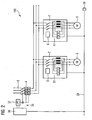
- FIG. 1 shows a three-pole switchgear assembly 100 according to the prior art. Except for the modules 4 and 9, all assemblies shown 2, 5, 7, 18 are mounted in a row, such as on a DIN rail.
- a power supply network 16 In the right part of the FIG. 1 is a power supply network 16 to see, to which a circuit breaker 4 is connected to achieve a short circuit protection.
- the power switch 4 is followed by a feed-in contactor 9, which in turn is connected upstream of a group of load branches 2.
- the three load feeders 2 are exemplary motor starters with an integrated overcurrent protection 17.
- the connected consumers 3 are three-phase electric motors.
- the feed-in contactor 9 is also connected via connecting lines 19 with a Verschaltungsbaumaschinence 18.
- the latter is connected in each case with a switch 21 of the load branches 2 and with a safety evaluation unit 5 such that the feed-in contactor 9 can be triggered in the case of one or more opened switches 21.
- a switch 21 of the load branches 2 and with a safety evaluation unit 5 such that the feed-in contactor 9 can be triggered in the case of one or more opened switches 21.
- the wiring of the switches 21 with the interconnection assembly 18 itself is not shown.
- the switches 21 are preferably connected in series and thus form a feedback loop.
- a control module 7 can be seen in the left part of the FIG. 1 . It is used for connection to a higher-level bus system 71, such as a Profibus or fieldbus.
- the control module 7 is further connected to an internal bus system 72, which connects the modules 2, 5, 7, 8 with each other in terms of data technology.
- the control module 7 thus converts the data traffic from the higher-level bus system 71 into the internal bus system 72 and vice versa.
- a switch-on button 51 and an emergency stop button 52 are connected.
- the safety evaluation unit 5 has means, not further shown, for reliably detecting the two buttons 51, 52. It also checks whether after pressing the emergency stop button 52 or after opening a safety switch, such as. a monitored door or a light curtain, the consumer 3 have been shut down safely. If the switch-on button 51 is pressed in the connection after switching on the switching arrangement 100, the safety evaluation unit 5 checks whether all the switches 21 of the load branches 2 are still closed. In the other case, the safety evaluation unit 5 triggers the feed-in contactor 9.
- FIG. 2 shows a further switching device arrangement according to the prior art.
- a power or circuit breaker 4 can be seen, which in the case of a short circuit separates the motor starters 2 shown from a power supply network 16.
- a trigger device 35 has a bus-capable safe ASi slave 36 and a trigger 37 which acts on a switching mechanism of the circuit breaker 4 to open.
- the two motor starters 2, the ASi slave 36 and a control device 38 or bus master are connected together on an ASi bus 39.
- the two motor starters 2 each have a contactor 6 for disconnecting an electric motor 3 from the power supply network 16. Furthermore, the motor starters 2 each have a current measuring device 61. If the respective motor starter 2 detects an overcurrent, it outputs a switch-off command to the tripping device 35 via the ASi bus 39. In a corresponding manner, a switch-off command is issued if, despite "allegedly" switched off contactor 6, a current flow to the load 3 should be measured. This is most often the case when the main contacts of the contactor 6 can not be opened due to a weld.
- FIG. 3 shows, by way of example, a switching device arrangement 100 with a group protection module 1.
- the switching device arrangement 100 shown is designed, for example, as a three-pole system. It can alternatively be single-pole, double-pole or more than three poles.
- the present switchgear assembly 100 is similar to the structure of FIGS FIG. 1 However, the circuit breaker assembly 18 is also missing.
- the load feeders 2 are again exemplary motor starters, the consumer 3 three-phase electric motors.
- the switching device arrangement 100 has a group protection module 1 for securing the load branches 2.
- the group protection module 1 has a circuit breaker 4 for achieving short-circuit protection.
- the circuit breaker 4 is connected to a network-side input 11 and to a consumer-side output 12 of the modular safety module 1 designed as a unit for connection to a power supply network 16 and for connecting the group of load branches 2.
- the group protection module 1 has a safety evaluation unit 5, via which the circuit breaker 4 can be triggered if a feedback detectable by the respective load branches 2 indicates that one of the contactors 6 of the load branches 2 can no longer be switched off.
- the feedback occurs in that the switching state of the respective switches 21 of the load branches 2 is detected and monitored by the safety evaluation unit 5.
- the respective switch 21 is in particular an auxiliary contact switch which is forcibly guided by the main contacts of the respective contactor 6 in the load branch 2.
- the respective switches 21 may, for example, be wired to a connection field 53 of the group protection module 1 arranged on a housing outside. If the safety evaluation unit 5 determines that at least one of the switches 21 is open, such as by impressing a test current or by applying a test voltage, a corresponding trigger signal via the internal connection lines not further specified between the safety evaluation unit 5 and the power switch 4 can be output.
- the control module 7 furthermore has a connection for connection to a higher-level bus system 71 and to an internal bus system 72. With the latter, at least the group protection module 1 and the connected load branches 2 are connected to one another in terms of data technology.
- FIG. 4 shows by way of example a group hedging module 1 with two series-connected consumer load branches 2, 2 'according to the invention.
- the second assembly 2 ' is - as far as the object of the invention is concerned - formed analog.
- the elements of the second assembly 2 ' are therefore provided with the same reference numerals as the respective corresponding elements of the first assembly 2, but in addition with an apostrophe.
- a group insurance module 1 can be seen, on which a second load branch 2 'is inserted. At the second load feeder 2 ', a first load feeder 2 is inserted.
- the assemblies 1, 2 ', 2 shown are designed in such a way that an automatically self-building feedback loop 50 is created by the juxtaposition, which can then be detected and checked by the group assurance module 1.
- the group protection module 1 has a first and second loop contact 14, 15 connected to the safety evaluation unit 5.
- Both loop contacts 14, 15 are components of a pre-assembled first connector 13.
- the first connector 13 is accessible from outside the housing 10 and configured such that a second connector 32 of a load feeder 2 'with the first connector 13 of the group hedging module 1 to build the feedback loop 50th is pluggable.
- the safety evaluation unit 5 triggers when the feedback loop 50 is interrupted.
- the safety evaluation unit 5 checks the feedback loop 50 for an interruption only after an emergency or safety shutdown.
- the first and second plug connection 13, 32 ' are arranged such that the second plug connection 32' of the load branch 2 'and the first plug connection 13 of the group protection module 1 are automatically plugged together when applying the load branch 2' to the group protection module 1.
- the first load branch 2 has a module housing 20, a switch 21, a feed contact 22, a return contact 23, a first and second relay contact 24, 25, a switching device 26 and a first and second actuator 27, 28.
- the switch 21 is preferably an auxiliary contact switch of the respective contactor 6 of the load branches 2.
- the switch 21 and the switching device 26 are arranged in the module housing 20.
- the feed contact 22 and the first relay contact 24 are connected via the switch 21.
- the return contact 23 and the second relay contact 25 are connected directly to each other.
- the feed contact 22, the return contact 23 and the first actuator 27 are components of a second pre-assembled connector 32 and the forwarding contacts 24, 25 and the second actuator 28 components of a third pre-assembled connector 33.
- the two connectors 32, 33 are of au-ßerraum of Module housing 20 accessible and designed such the second plug connection 32 of a first modular load branch 2 can be plugged together with the third plug connection 33 'of a second modular load branch 2'.
- the connectors 32, 33 ' are each one of the forwarding contacts 24', 25 'of the second load branch 2' connected to the feed contact 22 and the return contact 23 of the first load branch 2.
- the first actuating element 27 of the first load branch 2 acts on the second actuating element 28 'of the second load branch 2' such that the switching device 26 'of the second load branch 2' has a current path 29 'from the first to the second relay contact 24', 25 'of the second Load branch 2 'interrupts.
- the switching device 26 'of the left load branch 2' is opened by the second actuating element 28 'and that thus a test current impressed by the group protection module 1 is forced to flow to the next load branch 2.
- the switching device 26 of the right load feeder 2 is closed because no further load feeder 2 is connected to this. The test current can therefore flow back to the group protection module 1 via the closed switching device 26.
- the connectors 32, 33 'of the load branches 2, 2' arranged such that the second connector 32 of the first load branch 2 and the third connector 33 'of the second load branch 2' when attaching the first load branch 2 to the second load branch 2 'automatically be put together.
- FIG. 5 shows an embodiment of connectors 13, 32, 33 for connecting the group hedging module 1 with, for example, only one load feeder 2.
- the switching device 26 formed as a mechanical switching device.
- the actuators 27, 28 are formed as mechanical actuators.
- the switching device may alternatively be formed as an electronic switching device.
- the actuators may alternatively be formed as electrically cooperating contacts.
- the first connector 13 is a socket which is formed as a recess 30 in the housing 10 of the group hedging module 1.
- the two loop contacts 14, 15 are designed as surface contacts, which contact a corresponding supply and return contact 22, 23 upon insertion of a connector 13 corresponding to the connector 32 of a load feeder 2.
- the plug 32 is formed as a projection 31 on an outer side of the load branch 2.
- the first actuating element 27 is formed as a lateral lug on the plug 32, which deflects a movable counterpart 28 when inserting the plug 32 into the socket 33 of a further load branch not shown. This counterpart 28 acts on a movable contact of the switching device 26 so that it opens.
- the group protection module 1 can also have a switching device, which is connected between the two loop contacts 14, 15. This can cooperate with another second actuating element such that the switching device is automatically opened when plugging in a load feeder 2.
- FIG. 6 shows a further embodiment of connectors 11, 32, 33 for connecting the group hedging module 1 with, for example, only a load feeder 2.
- the embodiments of the connectors 13, 32, 33 in the reverse manner, that is, the first and third connector 13, 33rd as a plug and the second connector 32 as a socket.
Priority Applications (9)
| Application Number | Priority Date | Filing Date | Title |
|---|---|---|---|
| AT07013517T ATE456151T1 (de) | 2007-07-10 | 2007-07-10 | Gruppenabsicherungsmodul für eine schaltgeräteanordnung sowie schaltgeräteanordnung mit einem derartigen gruppenabsicherungsmodul |
| EP07013517A EP2015341B1 (de) | 2007-07-10 | 2007-07-10 | Gruppenabsicherungsmodul für eine Schaltgeräteanordnung sowie Schaltgeräteanordnung mit einem derartigen Gruppenabsicherungsmodul |
| DE502007002681T DE502007002681D1 (de) | 2007-07-10 | 2007-07-10 | Gruppenabsicherungsmodul für eine Schaltgeräteanordnung sowie Schaltgeräteanordnung mit einem derartigen Gruppenabsicherungsmodul |
| ES07013517T ES2336710T3 (es) | 2007-07-10 | 2007-07-10 | Modulo de proteccion de grupo para una configuracion de aparatos de maniobra asi como configuracion de aparatos de maniobra con un tal modulo de proteccion de grupo. |
| CN200810099765XA CN101345173B (zh) | 2007-07-10 | 2008-06-04 | 成组保险模块及具有该成组保险模块的开关设备装置 |
| CA2637113A CA2637113C (en) | 2007-07-10 | 2008-07-08 | Group protection module for a switchgear arrangement and switchgear arrangement having such a group protection module |
| JP2008178442A JP4741638B2 (ja) | 2007-07-10 | 2008-07-08 | スイッチギア装置のためのグループ保護モジュール及びかかるグループ保護モジュールを有するスイッチギア装置 |
| US12/218,071 US7974058B2 (en) | 2007-07-10 | 2008-07-10 | Group protection module for a switchgear arrangement and switchgear arrangement having such a group protection module |
| KR1020080067118A KR101012559B1 (ko) | 2007-07-10 | 2008-07-10 | 개폐장치 배열체를 위한 그룹 보호 모듈 및 이러한 그룹보호 모듈을 갖는 개폐장치 배열체 |
Applications Claiming Priority (1)
| Application Number | Priority Date | Filing Date | Title |
|---|---|---|---|
| EP07013517A EP2015341B1 (de) | 2007-07-10 | 2007-07-10 | Gruppenabsicherungsmodul für eine Schaltgeräteanordnung sowie Schaltgeräteanordnung mit einem derartigen Gruppenabsicherungsmodul |
Publications (2)
| Publication Number | Publication Date |
|---|---|
| EP2015341A1 EP2015341A1 (de) | 2009-01-14 |
| EP2015341B1 true EP2015341B1 (de) | 2010-01-20 |
Family
ID=38537911
Family Applications (1)
| Application Number | Title | Priority Date | Filing Date |
|---|---|---|---|
| EP07013517A Active EP2015341B1 (de) | 2007-07-10 | 2007-07-10 | Gruppenabsicherungsmodul für eine Schaltgeräteanordnung sowie Schaltgeräteanordnung mit einem derartigen Gruppenabsicherungsmodul |
Country Status (9)
| Country | Link |
|---|---|
| US (1) | US7974058B2 (zh) |
| EP (1) | EP2015341B1 (zh) |
| JP (1) | JP4741638B2 (zh) |
| KR (1) | KR101012559B1 (zh) |
| CN (1) | CN101345173B (zh) |
| AT (1) | ATE456151T1 (zh) |
| CA (1) | CA2637113C (zh) |
| DE (1) | DE502007002681D1 (zh) |
| ES (1) | ES2336710T3 (zh) |
Cited By (1)
| Publication number | Priority date | Publication date | Assignee | Title |
|---|---|---|---|---|
| DE102010038459A1 (de) * | 2010-07-27 | 2012-02-02 | Siemens Aktiengesellschaft | Sicherheitssystem |
Families Citing this family (15)
| Publication number | Priority date | Publication date | Assignee | Title |
|---|---|---|---|---|
| US8180948B2 (en) * | 2009-07-09 | 2012-05-15 | Phoenix Contact America, Inc. | Two-wire loop process IO transmitter powered from the two-wire loop |
| DE102009035166A1 (de) * | 2009-07-29 | 2011-03-17 | Areva Energietechnik Gmbh | Verfahren zum Betreiben eines elektrischen Energieversorgungsnetzes |
| TW201318284A (zh) * | 2011-10-21 | 2013-05-01 | Acer Inc | 用於電腦系統之公連接座及母連接座 |
| EP2720414B1 (de) * | 2012-10-10 | 2014-12-10 | Sick Ag | Bussystem |
| DE102013103020A1 (de) * | 2013-03-25 | 2014-09-25 | Hamilton Sundstrand Corporation | Digitaler Master-Slave-Stromkreisunterbrecher |
| WO2015168221A1 (en) * | 2014-04-29 | 2015-11-05 | Bretford Manufacturing, Inc. | Recessed power system |
| EP3176903B1 (en) * | 2015-12-04 | 2023-09-20 | HS Elektronik Systeme GmbH | Power distribution system |
| EP3382735B1 (de) * | 2017-03-31 | 2019-05-08 | Sick AG | Modulare sicherheitssteuerung zum sicheren steuern zumindest einer maschine |
| FR3069716B1 (fr) | 2017-07-25 | 2019-09-06 | Schneider Electric Industries Sas | Dispositif electrique pour l'alimentation electrique d'appareils electriques de puissance |
| DE102017215729A1 (de) * | 2017-09-07 | 2019-03-07 | Zf Friedrichshafen Ag | Verbindungsvorrichtung und Verfahren zum elektrischen Verbinden eines Elektromotors mit einer elektronischen Schalteinheit, elektronische Schalteinheit, Verbindungseinheit und Vorrichtungssystem mit zumindest einer Verbindungsvorrichtung |
| CN113551804A (zh) * | 2020-04-03 | 2021-10-26 | 首瑞(天津)电气设备有限公司 | 一种开关成套系统 |
| CN112467566A (zh) * | 2020-12-09 | 2021-03-09 | 上海宝临电气集团有限公司 | 一种配电箱 |
| KR102457719B1 (ko) * | 2020-12-21 | 2022-10-21 | 시엔에이전기 주식회사 | 멀티모터구동시스템 |
| EP4246549A1 (de) * | 2022-03-15 | 2023-09-20 | Siemens Aktiengesellschaft | Verfahren zur steuerung von schaltzuständen |
| KR102640484B1 (ko) * | 2022-11-23 | 2024-02-23 | 임정상 | 커넥터, 전력 부스바, 이들을 포함하는 전력 분배 장치 및 이들의 사용 방법 |
Family Cites Families (14)
| Publication number | Priority date | Publication date | Assignee | Title |
|---|---|---|---|---|
| US3912889A (en) * | 1974-02-14 | 1975-10-14 | Bendix Corp | Electrical connector having an internal switch |
| GB8309226D0 (en) | 1983-04-05 | 1983-05-11 | Fairford Electronics Ltd | Start-up control method |
| JPS6149323A (ja) * | 1984-08-17 | 1986-03-11 | 大同特殊鋼株式会社 | 主遮断器引外し回路 |
| JPS6412897A (en) * | 1987-07-06 | 1989-01-17 | Toshiba Corp | Motor group centralized control device |
| JPS6412897U (zh) | 1987-07-15 | 1989-01-23 | ||
| JPH04179335A (ja) * | 1990-11-14 | 1992-06-26 | Toshiba Corp | データ伝送システム |
| JPH0917313A (ja) * | 1995-06-30 | 1997-01-17 | Mitsubishi Electric Corp | 負荷回路保護装置 |
| JP4290232B2 (ja) * | 1997-02-24 | 2009-07-01 | 富士通株式会社 | ヒートシンクとそれを使用する情報処理装置 |
| US6169651B1 (en) | 1998-06-05 | 2001-01-02 | General Electric Company | Protective relay with modular control panel |
| DE10102316A1 (de) * | 2001-01-19 | 2002-07-25 | Moeller Gmbh | Motorstarteranordnung |
| DE10119458B4 (de) * | 2001-04-20 | 2004-08-19 | Siemens Ag | Schaltgeräteeinheit für einen Verbraucher, insbesondere Motorstarter |
| DE10148155A1 (de) * | 2001-09-28 | 2003-04-24 | Moeller Gmbh | Anordnung zur Überwachung von Motorstartern |
| KR100492758B1 (ko) | 2003-02-25 | 2005-06-07 | 엘에스산전 주식회사 | 하이브리드 모터 스타터의 정지 제어회로 |
| US7371981B2 (en) * | 2004-02-20 | 2008-05-13 | Masimo Corporation | Connector switch |
-
2007
- 2007-07-10 EP EP07013517A patent/EP2015341B1/de active Active
- 2007-07-10 AT AT07013517T patent/ATE456151T1/de active
- 2007-07-10 ES ES07013517T patent/ES2336710T3/es active Active
- 2007-07-10 DE DE502007002681T patent/DE502007002681D1/de active Active
-
2008
- 2008-06-04 CN CN200810099765XA patent/CN101345173B/zh active Active
- 2008-07-08 CA CA2637113A patent/CA2637113C/en not_active Expired - Fee Related
- 2008-07-08 JP JP2008178442A patent/JP4741638B2/ja not_active Expired - Fee Related
- 2008-07-10 US US12/218,071 patent/US7974058B2/en not_active Expired - Fee Related
- 2008-07-10 KR KR1020080067118A patent/KR101012559B1/ko active IP Right Grant
Cited By (1)
| Publication number | Priority date | Publication date | Assignee | Title |
|---|---|---|---|---|
| DE102010038459A1 (de) * | 2010-07-27 | 2012-02-02 | Siemens Aktiengesellschaft | Sicherheitssystem |
Also Published As
| Publication number | Publication date |
|---|---|
| CN101345173A (zh) | 2009-01-14 |
| JP4741638B2 (ja) | 2011-08-03 |
| EP2015341A1 (de) | 2009-01-14 |
| ES2336710T3 (es) | 2010-04-15 |
| CA2637113A1 (en) | 2009-01-10 |
| ATE456151T1 (de) | 2010-02-15 |
| CA2637113C (en) | 2012-08-21 |
| KR101012559B1 (ko) | 2011-02-07 |
| DE502007002681D1 (de) | 2010-03-11 |
| JP2009022158A (ja) | 2009-01-29 |
| CN101345173B (zh) | 2012-06-06 |
| US20090040673A1 (en) | 2009-02-12 |
| US7974058B2 (en) | 2011-07-05 |
| KR20090006018A (ko) | 2009-01-14 |
Similar Documents
| Publication | Publication Date | Title |
|---|---|---|
| EP2015341B1 (de) | Gruppenabsicherungsmodul für eine Schaltgeräteanordnung sowie Schaltgeräteanordnung mit einem derartigen Gruppenabsicherungsmodul | |
| EP2048679B1 (de) | Lasttrenner-Anordnung | |
| EP2375526B1 (de) | Elektrische Niederspannungsgebäudeinstallation | |
| JP2009022158A6 (ja) | スイッチギア装置のためのグループ保護モジュール及びかかるグループ保護モジュールを有するスイッチギア装置 | |
| WO2002031929A1 (de) | Verbindung für verteilungsnetz | |
| EP2727125B1 (de) | Sicherer motorstarter | |
| DE102006004337B4 (de) | Stromverbindungsvorrichtung für eine Batteriepolklemme | |
| EP2606546B1 (de) | Schaltgerät | |
| DE102017215820A1 (de) | Leistungsschalter und Verfahren | |
| EP1938356A1 (de) | Überwachung einer vorgeschalteten schutzeinrichtung an einem schaltgerät | |
| EP1364459B1 (de) | Sicherheitsschaltvorrichtung | |
| EP3726560A1 (de) | Kompakt-schutzschaltgerät | |
| AT519847B1 (de) | Elektrische Schalteinrichtung | |
| DE102008018256B4 (de) | Steuermodul mit Anschlusseinrichtungen zum Anschluss an Anschlussklemmen eines Verbraucherabzweiges sowie Verbraucherabzweig | |
| EP2140470B1 (de) | Baugruppe mit automatischer erweiterung eines überwachungskreises | |
| EP2064721B1 (de) | Schaltgerät mit integriertem hauptstrombahn-abgriff | |
| EP0889569B1 (de) | Installationsschaltereinheit | |
| EP1298689A2 (de) | Anordnung zur Überwachung von Motorstartern | |
| DE10041633A1 (de) | Schaltgeräteanordnung | |
| DE102019220444B4 (de) | Fernantrieb und Parametrier-Verfahren | |
| DE102020200993B4 (de) | Fernantrieb, Anordnung mit einem Fernantrieb sowie Verfahren | |
| DE10102316A1 (de) | Motorstarteranordnung | |
| DE19925965A1 (de) | Schaltanlage mit Trennschaltern und Leistungsschaltern | |
| DE10009498A1 (de) | Sichere Schaltbaugruppe, sichere Ansteuerbaugruppe und Baugruppensystem |
Legal Events
| Date | Code | Title | Description |
|---|---|---|---|
| PUAI | Public reference made under article 153(3) epc to a published international application that has entered the european phase |
Free format text: ORIGINAL CODE: 0009012 |
|
| 17P | Request for examination filed |
Effective date: 20080124 |
|
| AK | Designated contracting states |
Kind code of ref document: A1 Designated state(s): AT BE BG CH CY CZ DE DK EE ES FI FR GB GR HU IE IS IT LI LT LU LV MC MT NL PL PT RO SE SI SK TR |
|
| AX | Request for extension of the european patent |
Extension state: AL BA HR MK RS |
|
| GRAP | Despatch of communication of intention to grant a patent |
Free format text: ORIGINAL CODE: EPIDOSNIGR1 |
|
| AKX | Designation fees paid |
Designated state(s): AT BE BG CH CY CZ DE DK EE ES FI FR GB GR HU IE IS IT LI LT LU LV MC MT NL PL PT RO SE SI SK TR |
|
| GRAS | Grant fee paid |
Free format text: ORIGINAL CODE: EPIDOSNIGR3 |
|
| GRAA | (expected) grant |
Free format text: ORIGINAL CODE: 0009210 |
|
| AK | Designated contracting states |
Kind code of ref document: B1 Designated state(s): AT BE BG CH CY CZ DE DK EE ES FI FR GB GR HU IE IS IT LI LT LU LV MC MT NL PL PT RO SE SI SK TR |
|
| REG | Reference to a national code |
Ref country code: GB Ref legal event code: FG4D Free format text: NOT ENGLISH |
|
| REG | Reference to a national code |
Ref country code: CH Ref legal event code: EP Ref country code: CH Ref legal event code: NV Representative=s name: SIEMENS SCHWEIZ AG |
|
| REG | Reference to a national code |
Ref country code: IE Ref legal event code: FG4D |
|
| REF | Corresponds to: |
Ref document number: 502007002681 Country of ref document: DE Date of ref document: 20100311 Kind code of ref document: P |
|
| REG | Reference to a national code |
Ref country code: ES Ref legal event code: FG2A Ref document number: 2336710 Country of ref document: ES Kind code of ref document: T3 |
|
| REG | Reference to a national code |
Ref country code: SE Ref legal event code: TRGR |
|
| REG | Reference to a national code |
Ref country code: NL Ref legal event code: VDEP Effective date: 20100120 |
|
| LTIE | Lt: invalidation of european patent or patent extension |
Effective date: 20100120 |
|
| PG25 | Lapsed in a contracting state [announced via postgrant information from national office to epo] |
Ref country code: PT Free format text: LAPSE BECAUSE OF FAILURE TO SUBMIT A TRANSLATION OF THE DESCRIPTION OR TO PAY THE FEE WITHIN THE PRESCRIBED TIME-LIMIT Effective date: 20100520 Ref country code: NL Free format text: LAPSE BECAUSE OF FAILURE TO SUBMIT A TRANSLATION OF THE DESCRIPTION OR TO PAY THE FEE WITHIN THE PRESCRIBED TIME-LIMIT Effective date: 20100120 Ref country code: IS Free format text: LAPSE BECAUSE OF FAILURE TO SUBMIT A TRANSLATION OF THE DESCRIPTION OR TO PAY THE FEE WITHIN THE PRESCRIBED TIME-LIMIT Effective date: 20100520 Ref country code: LT Free format text: LAPSE BECAUSE OF FAILURE TO SUBMIT A TRANSLATION OF THE DESCRIPTION OR TO PAY THE FEE WITHIN THE PRESCRIBED TIME-LIMIT Effective date: 20100120 |
|
| REG | Reference to a national code |
Ref country code: IE Ref legal event code: FD4D |
|
| PG25 | Lapsed in a contracting state [announced via postgrant information from national office to epo] |
Ref country code: SI Free format text: LAPSE BECAUSE OF FAILURE TO SUBMIT A TRANSLATION OF THE DESCRIPTION OR TO PAY THE FEE WITHIN THE PRESCRIBED TIME-LIMIT Effective date: 20100120 Ref country code: PL Free format text: LAPSE BECAUSE OF FAILURE TO SUBMIT A TRANSLATION OF THE DESCRIPTION OR TO PAY THE FEE WITHIN THE PRESCRIBED TIME-LIMIT Effective date: 20100120 Ref country code: LV Free format text: LAPSE BECAUSE OF FAILURE TO SUBMIT A TRANSLATION OF THE DESCRIPTION OR TO PAY THE FEE WITHIN THE PRESCRIBED TIME-LIMIT Effective date: 20100120 Ref country code: FI Free format text: LAPSE BECAUSE OF FAILURE TO SUBMIT A TRANSLATION OF THE DESCRIPTION OR TO PAY THE FEE WITHIN THE PRESCRIBED TIME-LIMIT Effective date: 20100120 |
|
| PG25 | Lapsed in a contracting state [announced via postgrant information from national office to epo] |
Ref country code: CY Free format text: LAPSE BECAUSE OF FAILURE TO SUBMIT A TRANSLATION OF THE DESCRIPTION OR TO PAY THE FEE WITHIN THE PRESCRIBED TIME-LIMIT Effective date: 20100120 Ref country code: EE Free format text: LAPSE BECAUSE OF FAILURE TO SUBMIT A TRANSLATION OF THE DESCRIPTION OR TO PAY THE FEE WITHIN THE PRESCRIBED TIME-LIMIT Effective date: 20100120 Ref country code: GR Free format text: LAPSE BECAUSE OF FAILURE TO SUBMIT A TRANSLATION OF THE DESCRIPTION OR TO PAY THE FEE WITHIN THE PRESCRIBED TIME-LIMIT Effective date: 20100421 Ref country code: IE Free format text: LAPSE BECAUSE OF FAILURE TO SUBMIT A TRANSLATION OF THE DESCRIPTION OR TO PAY THE FEE WITHIN THE PRESCRIBED TIME-LIMIT Effective date: 20100120 Ref country code: RO Free format text: LAPSE BECAUSE OF FAILURE TO SUBMIT A TRANSLATION OF THE DESCRIPTION OR TO PAY THE FEE WITHIN THE PRESCRIBED TIME-LIMIT Effective date: 20100120 |
|
| PLBE | No opposition filed within time limit |
Free format text: ORIGINAL CODE: 0009261 |
|
| STAA | Information on the status of an ep patent application or granted ep patent |
Free format text: STATUS: NO OPPOSITION FILED WITHIN TIME LIMIT |
|
| PG25 | Lapsed in a contracting state [announced via postgrant information from national office to epo] |
Ref country code: SK Free format text: LAPSE BECAUSE OF FAILURE TO SUBMIT A TRANSLATION OF THE DESCRIPTION OR TO PAY THE FEE WITHIN THE PRESCRIBED TIME-LIMIT Effective date: 20100120 Ref country code: CZ Free format text: LAPSE BECAUSE OF FAILURE TO SUBMIT A TRANSLATION OF THE DESCRIPTION OR TO PAY THE FEE WITHIN THE PRESCRIBED TIME-LIMIT Effective date: 20100120 Ref country code: BG Free format text: LAPSE BECAUSE OF FAILURE TO SUBMIT A TRANSLATION OF THE DESCRIPTION OR TO PAY THE FEE WITHIN THE PRESCRIBED TIME-LIMIT Effective date: 20100420 |
|
| 26N | No opposition filed |
Effective date: 20101021 |
|
| BERE | Be: lapsed |
Owner name: SIEMENS A.G. Effective date: 20100731 |
|
| PG25 | Lapsed in a contracting state [announced via postgrant information from national office to epo] |
Ref country code: DK Free format text: LAPSE BECAUSE OF FAILURE TO SUBMIT A TRANSLATION OF THE DESCRIPTION OR TO PAY THE FEE WITHIN THE PRESCRIBED TIME-LIMIT Effective date: 20100120 |
|
| PG25 | Lapsed in a contracting state [announced via postgrant information from national office to epo] |
Ref country code: MC Free format text: LAPSE BECAUSE OF NON-PAYMENT OF DUE FEES Effective date: 20100731 |
|
| PG25 | Lapsed in a contracting state [announced via postgrant information from national office to epo] |
Ref country code: BE Free format text: LAPSE BECAUSE OF NON-PAYMENT OF DUE FEES Effective date: 20100731 |
|
| PG25 | Lapsed in a contracting state [announced via postgrant information from national office to epo] |
Ref country code: MT Free format text: LAPSE BECAUSE OF FAILURE TO SUBMIT A TRANSLATION OF THE DESCRIPTION OR TO PAY THE FEE WITHIN THE PRESCRIBED TIME-LIMIT Effective date: 20100120 |
|
| PG25 | Lapsed in a contracting state [announced via postgrant information from national office to epo] |
Ref country code: LU Free format text: LAPSE BECAUSE OF NON-PAYMENT OF DUE FEES Effective date: 20100710 Ref country code: HU Free format text: LAPSE BECAUSE OF FAILURE TO SUBMIT A TRANSLATION OF THE DESCRIPTION OR TO PAY THE FEE WITHIN THE PRESCRIBED TIME-LIMIT Effective date: 20100721 |
|
| REG | Reference to a national code |
Ref country code: AT Ref legal event code: MM01 Ref document number: 456151 Country of ref document: AT Kind code of ref document: T Effective date: 20120731 |
|
| PG25 | Lapsed in a contracting state [announced via postgrant information from national office to epo] |
Ref country code: AT Free format text: LAPSE BECAUSE OF NON-PAYMENT OF DUE FEES Effective date: 20120731 |
|
| REG | Reference to a national code |
Ref country code: FR Ref legal event code: PLFP Year of fee payment: 10 |
|
| REG | Reference to a national code |
Ref country code: FR Ref legal event code: PLFP Year of fee payment: 11 |
|
| REG | Reference to a national code |
Ref country code: CH Ref legal event code: PCOW Free format text: NEW ADDRESS: WERNER-VON-SIEMENS-STRASSE 1, 80333 MUENCHEN (DE) |
|
| REG | Reference to a national code |
Ref country code: FR Ref legal event code: PLFP Year of fee payment: 12 |
|
| PGFP | Annual fee paid to national office [announced via postgrant information from national office to epo] |
Ref country code: GB Payment date: 20190702 Year of fee payment: 13 |
|
| PGFP | Annual fee paid to national office [announced via postgrant information from national office to epo] |
Ref country code: ES Payment date: 20191028 Year of fee payment: 13 |
|
| PGFP | Annual fee paid to national office [announced via postgrant information from national office to epo] |
Ref country code: CH Payment date: 20191002 Year of fee payment: 13 |
|
| PGFP | Annual fee paid to national office [announced via postgrant information from national office to epo] |
Ref country code: TR Payment date: 20200709 Year of fee payment: 14 |
|
| PGFP | Annual fee paid to national office [announced via postgrant information from national office to epo] |
Ref country code: SE Payment date: 20200713 Year of fee payment: 14 |
|
| REG | Reference to a national code |
Ref country code: CH Ref legal event code: PL |
|
| GBPC | Gb: european patent ceased through non-payment of renewal fee |
Effective date: 20200710 |
|
| PG25 | Lapsed in a contracting state [announced via postgrant information from national office to epo] |
Ref country code: CH Free format text: LAPSE BECAUSE OF NON-PAYMENT OF DUE FEES Effective date: 20200731 Ref country code: LI Free format text: LAPSE BECAUSE OF NON-PAYMENT OF DUE FEES Effective date: 20200731 Ref country code: GB Free format text: LAPSE BECAUSE OF NON-PAYMENT OF DUE FEES Effective date: 20200710 |
|
| REG | Reference to a national code |
Ref country code: ES Ref legal event code: FD2A Effective date: 20211228 |
|
| PG25 | Lapsed in a contracting state [announced via postgrant information from national office to epo] |
Ref country code: ES Free format text: LAPSE BECAUSE OF NON-PAYMENT OF DUE FEES Effective date: 20200711 |
|
| PG25 | Lapsed in a contracting state [announced via postgrant information from national office to epo] |
Ref country code: SE Free format text: LAPSE BECAUSE OF NON-PAYMENT OF DUE FEES Effective date: 20210711 |
|
| PGFP | Annual fee paid to national office [announced via postgrant information from national office to epo] |
Ref country code: IT Payment date: 20220720 Year of fee payment: 16 Ref country code: DE Payment date: 20220919 Year of fee payment: 16 |
|
| PGFP | Annual fee paid to national office [announced via postgrant information from national office to epo] |
Ref country code: FR Payment date: 20220721 Year of fee payment: 16 |
|
| P01 | Opt-out of the competence of the unified patent court (upc) registered |
Effective date: 20230510 |
|
| REG | Reference to a national code |
Ref country code: DE Ref legal event code: R119 Ref document number: 502007002681 Country of ref document: DE |
|
| PG25 | Lapsed in a contracting state [announced via postgrant information from national office to epo] |
Ref country code: DE Free format text: LAPSE BECAUSE OF NON-PAYMENT OF DUE FEES Effective date: 20240201 |