EP2015339B1 - Module de déclenchement et disjoncteur comprenant ce module - Google Patents
Module de déclenchement et disjoncteur comprenant ce module Download PDFInfo
- Publication number
- EP2015339B1 EP2015339B1 EP08011708A EP08011708A EP2015339B1 EP 2015339 B1 EP2015339 B1 EP 2015339B1 EP 08011708 A EP08011708 A EP 08011708A EP 08011708 A EP08011708 A EP 08011708A EP 2015339 B1 EP2015339 B1 EP 2015339B1
- Authority
- EP
- European Patent Office
- Prior art keywords
- trip
- reset
- actuator
- slider
- module
- Prior art date
- Legal status (The legal status is an assumption and is not a legal conclusion. Google has not performed a legal analysis and makes no representation as to the accuracy of the status listed.)
- Active
Links
Images


Classifications
-
- H—ELECTRICITY
- H01—ELECTRIC ELEMENTS
- H01H—ELECTRIC SWITCHES; RELAYS; SELECTORS; EMERGENCY PROTECTIVE DEVICES
- H01H71/00—Details of the protective switches or relays covered by groups H01H73/00 - H01H83/00
- H01H71/10—Operating or release mechanisms
- H01H71/1045—Multiple circuits-breaker, e.g. for the purpose of dividing current or potential drop
-
- H—ELECTRICITY
- H01—ELECTRIC ELEMENTS
- H01H—ELECTRIC SWITCHES; RELAYS; SELECTORS; EMERGENCY PROTECTIVE DEVICES
- H01H71/00—Details of the protective switches or relays covered by groups H01H73/00 - H01H83/00
- H01H71/10—Operating or release mechanisms
- H01H71/12—Automatic release mechanisms with or without manual release
- H01H71/44—Automatic release mechanisms with or without manual release having means for introducing a predetermined time delay
-
- H—ELECTRICITY
- H01—ELECTRIC ELEMENTS
- H01H—ELECTRIC SWITCHES; RELAYS; SELECTORS; EMERGENCY PROTECTIVE DEVICES
- H01H71/00—Details of the protective switches or relays covered by groups H01H73/00 - H01H83/00
- H01H71/10—Operating or release mechanisms
- H01H71/50—Manual reset mechanisms which may be also used for manual release
- H01H71/505—Latching devices between operating and release mechanism
-
- H—ELECTRICITY
- H01—ELECTRIC ELEMENTS
- H01H—ELECTRIC SWITCHES; RELAYS; SELECTORS; EMERGENCY PROTECTIVE DEVICES
- H01H71/00—Details of the protective switches or relays covered by groups H01H73/00 - H01H83/00
- H01H71/10—Operating or release mechanisms
- H01H71/50—Manual reset mechanisms which may be also used for manual release
- H01H71/58—Manual reset mechanisms which may be also used for manual release actuated by push-button, pull-knob, or slide
-
- H—ELECTRICITY
- H01—ELECTRIC ELEMENTS
- H01H—ELECTRIC SWITCHES; RELAYS; SELECTORS; EMERGENCY PROTECTIVE DEVICES
- H01H73/00—Protective overload circuit-breaking switches in which excess current opens the contacts by automatic release of mechanical energy stored by previous operation of a hand reset mechanism
- H01H73/36—Protective overload circuit-breaking switches in which excess current opens the contacts by automatic release of mechanical energy stored by previous operation of a hand reset mechanism having electromagnetic release and no other automatic release
- H01H73/44—Protective overload circuit-breaking switches in which excess current opens the contacts by automatic release of mechanical energy stored by previous operation of a hand reset mechanism having electromagnetic release and no other automatic release reset by push-button, pull-knob or slide
Definitions
- the present invention relates to a trip device module and a circuit breaker implementing the same, and particularly, to a trip device module which is usable in devices having different spacings between the phases, and to a circuit breaker implementing the same.
- a so-called circuit breaker refers to an electric protection apparatus which is installed between an electrical power source and load equipment in order to protect the load equipment and a supply line from a fault current (a short circuit, excess current due to an earth fault, etc.) which may occur in an electrical circuit.
- a fault current a short circuit, excess current due to an earth fault, etc.
- a circuit breaker includes a switching mechanism for switching a fixed contactor and a movable contactor, an overcurrent relay for detecting a fault current and outputting a trip command so as to block the conducting of excess current, and a trip device module disposed between the switching mechanism and the overcurrent relay for generating a mechanical manipulation force when the overcurrent relay outputs the trip command and transferring the mechanical manipulation force to the switching mechanism.
- the circuit breaker includes other devices for executing additional functions, such as a trip alarming function for externally informing when a trip function of the trip device module is performed, and a time delay output function for allowing the excess current relay to perform an MCR (Making Current Release).
- a trip alarming function for externally informing when a trip function of the trip device module is performed
- a time delay output function for allowing the excess current relay to perform an MCR (Making Current Release).
- the main body of the circuit breaker may be increased in size and a great deal of time and effort is required for their assembly. Furthermore, upon the synchronization or interworking with each device, it is difficult to enhance the operational reliability of the circuit breaker.
- a trip device module which is adopted to be disposed between an overcurrent relay and a switching mechanism for switching on or off contactors to be connected to the switching mechanism and which generates a manipulation force when the overcurrent relay outputs a trip signal to allow the switching mechanism to perform a tripping operation
- the trip device module including: a case having first and second arm receiving pockets to receive driving arms disposed at a main shaft with various different inter-phase spacings, an actuator received in the case and having an output portion drawn out or introduced thereinto when the overcurrent relay outputs the trip signal, a reset plate installed in the case to interwork with the main shaft so as to initialize the output portion of the actuator, and a trip slider configured to allow the switching mechanism to perform the tripping operation when the actuator performs a tripping operation.
- the driving arms may include a reset plate driving arm disposed to be contacted by the reset plate and movable contactor driving arms connected to the movable contactor.
- the reset plate driving arm may be received in the first arm receiving pocket and the movable contactor driving arms may be received in the second arm receiving pocket.
- the driving arms may be connected to the movable contactor as well as coming into contact with the reset plate, and be received in the first arm receiving pocket.
- the trip device module may further include an actuator reset unit for interworking with the reset plate to reset the actuator to its initial position.
- the actuator reset unit may include a slider disposed at one side of the reset plate to be movable by being pressed upon when the reset plate is rotated, and a reset arm having one side contacted by the slider so as to be rotated and the other side pressing upon the mover of the actuator so as to reset the actuator to its initial position.
- the slider may include a housing, and a reset pin protruding from the housing so as to be in contact with the reset arm.
- the actuator reset unit may further include a smoothing member disposed between the reset plate and the mover of the actuator and being compressed after the mover of the actuator is reset to its initial position.
- the trip device module may further include a time delay output device interworking with the main shaft to output a signal with a preset time delay after the fixed contactor and the movable contactor come into contact with each other.
- the time delay output device may include a switch disposed at one side of the main shaft, a delay member disposed between the main shaft and the switch to be rotated by interworking with the rotation of the main shaft and configured to operate the switch with a preset delay time after the fixed contactor and the movable contactor come into contact with each other, and a delay member spring having one end connected to the delay member so as to apply an elastic force in a direction such that the delay member is urged into contact with the switch when the main shaft is rotated in a closing direction, and to apply an elastic force in a direction such that the delay member is kept spaced apart from the switch when the main shaft is rotated in an opening direction.
- the trip device module may further include an overcurrent relay interworking trip device interworking with the detachment of the overcurrent relay to allow the switching mechanism to be tripped.
- the overcurrent relay interworking trip device may include a rotational shaft portion rotatably installed at the trip device module, an operation arm extending in a radial direction from one region of the rotational shaft portion to come into contact with the overcurrent relay, a driving arm extending from another region of the rotational shaft portion so as to be rotated simultaneously with the rotational shaft portion for thereby pressing upon the trip device module to perform the trip operation, and an elastic member configured to apply an elastic force in a direction such that the operation arm is urged into contact with the overcurrent relay.
- the trip slider may be provided with a driving protrusion protruding to come into contact with the driving arm.
- a guiding portion may be formed in the case to guide the overcurrent relay.
- the trip device module may further include a trip signal output device interworking with the actuator to output a trip signal to the exterior when the actuator performs the trip operation.
- the trip signal output device may include a switch configured to output a signal upon being contacted, and an interworking member interworking with the trip slider to come into contact with the switch when the trip slider is at a trip position.
- the trip signal output device may further include a contact piece interposed between the interworking member and the switch.
- the trip device module may further include a reset unit configured to reset the trip signal output device to its initial position.
- the trip device module may further comprise a pressing slider slidably disposed at one side of the trip slider to press the trip slider towards a trip position, and a trip slider spring configured to apply an elastic force so as to move the pressing slider towards the trip position, wherein the reset unit may include a reset arm disposed at one side of the pressing slider to be rotatable between the trip position and a closing position, and configured to move the pressing slider to the closing position.
- the trip device module may further include a latch member rotatable between a fixing position of fixing the pressing slider to the closing position and a release position of releasing the fixed pressing slider, and a latch member spring configured to apply an elastic member such that the latch member is rotated towards the fixing position, wherein the trip slider may be reset to the closing position by the latch member when the pressing slider is at the trip position.
- the reset unit may further include a reset rod protruded by interworking with the reset arm to be exposed from one side of the overcurrent relay to the exterior, and resetting the reset arm to the closing position upon being pressed.
- the reset unit may further include a reset rod spring configured to apply an elastic force such that the reset rod is moved toward the reset arm.
- the reset unit may further include a reset button installed to have one region thereof exposed to the outside and another region thereof coupled to the reset rod.
- the trip device module may further include a time delay output device interworking with the main shaft to output a signal with a preset time delay after the fixed contactor comes into contact with the movable contactor, an overcurrent relay interworking trip device interworking with the detachment of the overcurrent relay to allow the switching mechanism to be tripped, and a trip signal output device interworking with the actuator to output a trip signal to the exterior when the actuator performs the trip operation.
- a circuit breaker implementing such a trip device module may include a circuit breaker main body including a fixed contactor and a movable contactor, a main shaft, and a switching mechanism interworking with the main shaft and the movable contactor to switch on or off the fixed contactor and the movable contactor, an overcurrent relay coupled to the main body of the circuit breaker to detect a fault current, and the aforesaid trip device module interposed between the overcurrent relay and the switching mechanism.
- the circuit breaker may further include an actuator reset unit interworking with the reset plate to reset the actuator to its initial position.
- the circuit breaker may further include a time delay output device interworking with the main shaft to output a signal with a preset time delay after the fixed contactor comes in contact with the movable contactor.
- the circuit breaker may further include an overcurrent relay interworking trip device interworking with the detachment of the overcurrent relay to allow the switching mechanism to be tripped.
- the circuit breaker may further include a trip signal output device interworking with the actuator to output a trip signal to the exterior when the actuator performs a trip operation.
- the circuit breaker may further include a time delay output device interworking with the main shaft to output a signal with a preset time delay after the fixed contactor comes in contact with the movable contactor, an overcurrent relay interworking trip device interworking with the detachment of the overcurrent relay to allow the switching mechanism to be tripped, and a trip signal output device interworking with the actuator to output a trip signal to the exterior when the actuator performs a trip operation.
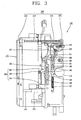
- the circuit breaker having the trip device module may include a main body 110 disposing a fixed contactor and a movable contactor therein, a main shaft 111, and a switching mechanism 117 interposed between the movable contactor and the main shaft 111 to switch the fixed contactor and the movable contactor on or off, a front surface cover 120 coupled onto the front surface of the main body 110, an overcurrent relay 131 coupled to the front surface cover 120 such that its front surface can be exposed and for detecting a fault current and outputting a trip signal (command), and a trip device module 140 having an actuator 161 which generates a manipulation force when the overcurrent relay 131 outputs the trip signal so as to be couplable to the main shaft 111 having different inter-phase spacings.
- An opening 122 is formed in the front surface cover 120 to expose the overcurrent relay 131 to the exterior.
- a trip button 125 and a closing button 126 are respectively provided at the front surface cover 120 so as to manually switch the switching mechanism 117 on or off.
- the trip device module 140 is installed at the rear side of the overcurrent relay 131.
- the switching mechanism 117 is disposed at one side of the trip device module 140 to thusly perform a tripping operation of the fixed contactor and the movable contactor according to the trip command upon detecting a fault current of the overcurrent relay 131.
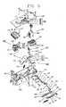
- the trip device module 140 may include a case 141 having first and second arm receiving pockets 148 and 149 (refer to Figs. 6 and 7 ) recessed and sized so as to accommodatingly receive driving arms disposed the main shaft 111 with various inter-phase spacings, an actuator 161 received in the case 141 to generate a manipulation force when the overcurrent relay 131 outputs the trip signal, a reset plate 171 installed in the case 141 to interwork with the main shaft 111 so as to initialize an output portion of the actuator 161, and a trip slider 181 slidable along the case 141 and connected to the switching mechanism 117 so as to allow the tripping operation of the switching mechanism 117 when the actuator 161 performs a tripping operation.
- the trip device module 140 may further include a time delay output device 250 interworking with the main shaft 111 to output a signal with a preset time delay after the fixed contactor comes in contact with the movable contactor, an overcurrent relay interworking trip device 280 interworking with the detaching of the overcurrent relay 131 to allow the switching mechanism 1117 to be tripped, and a trip signal output device 290 interworking with the actuator 161 to output a trip signal to the exterior when the actuator 161 performs the trip operation.
- a time delay output device 250 interworking with the main shaft 111 to output a signal with a preset time delay after the fixed contactor comes in contact with the movable contactor
- an overcurrent relay interworking trip device 280 interworking with the detaching of the overcurrent relay 131 to allow the switching mechanism 1117 to be tripped
- a trip signal output device 290 interworking with the actuator 161 to output a trip signal to the exterior when the actuator 161 performs the trip operation.
- the case 141 may include a case main body 142a having an opened receiving space therein and having an opening at its front side, and a case cover 142b for being integrally fixed to the case main body 142a by plural screws 143 so as to close the opening at the front side of the case main body 142a.
- the case main body 142a may be provided with guiding portions 150 to slidably guide the overcurrent relay 131 when the overcurrent relay 131 is detached.
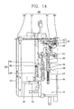
- Rails 133 (refer to Fig. 14 ) are respectively disposed at both side surfaces of the overcurrent relay 131 to be slidably received in the guiding portions 150.
- the main shaft 111 may include a plurality of movable contactor driving arms for driving the movable contactor of each phase spaced apart from each other to have different inter-phase spacings, and a switching mechanism driving arm connected to the switching mechanism 117.
- a plurality of movable contactor driving arms 113 with a relatively short inter-phase spacing L1 are arranged at intervals along a first main shaft 112a having a relatively small capacity (e.g., 2000A).
- a plurality of movable contactor driving arms 113 with a relatively long inter-phase distance L2 are arranged at intervals along a second main shaft 112a having a relatively greater capacity (e.g., 4000A).
- the second main shaft 112b is configured such that a reset plate driving arm 114 is spaced apart from the movable contactor driving arms 113 due to its relatively long inter-phase spacing.
- the first main shaft 112a may not separately have any reset plate driving arm because the movable contactor driving arms 113 drive the movable contactor and the reset plate 171. Therefore, the second arm receiving pocket 149 exists as an empty space.
- the first main shaft 112a hereinafter, called the main shaft 111) at which the reset plate driving arm and the movable contactor driving arms are integrated with each other will be exemplarily described.
- the actuator 161 which generates a manipulation force when the overcurrent relay 131 outputs the trip command and the reset plate 171 rotated by interworking with the main shaft 111 to reset an operation portion of the actuator 161 are installed in the case 141.
- the actuator 161 may include a stator 162 which generates a magnetic force when power is applied thereto, a mover 165 protruded by the magnetic force of the stator 162, and a spring 169 which applies an elastic force in a direction such that the mover 165 is urged to be protruded.
- the stator 162 may include a case 163 and a coil 164 disposed inside the case 163.
- An operation portion 167 interworking with the mover 165 is installed at one end of the actuator 161.
- the operation portion 167 is composed of two parts, which are both protruded toward the reset plate 171 when the mover 165 is protruded.
- One end portion of the reset plate 171 is pivotably disposed on a rotation shaft 173, and a curved end portion 174 which drives the time delay output device 250 is formed at the other end portion of the reset plate 171.
- Circlips 176 are coupled to both ends of the rotation shaft 173.
- a reset arm portion 175 is curvedly formed at the side portion of the reset plate 171 at an end of the rotational shaft 173 such that it can press upon one of the operation portions 167 of the actuator 161 to return the actuator 161 to its initial position.
- An actuator reset unit 230 is provided between the main shaft 111 and the actuator 161 to reset (return) the actuator 161 to its initial position.
- the actuator rest unit 230 may include the reset plate 171 interworking with the main shaft 111, a slider 231 disposed at one side of the reset plate 171 and pressed to be moved when the reset plate 171 is rotated, and a reset arm 238 having one end contacted by the slider 231 to be rotated and the other side pressing upon the mover 165 of the actuator 161 to reset the actuator 161 to its initial position.
- the reset arm 238 may be provided with a reset spring 239 which applies an elastic force to the reset arm 238 to urge it towards its initial position.
- the slider 231 may include a housing 233, a reset pin 235 coupled to be drawn out of or introduced into the housing 233, and a smoothing member 237 disposed in the housing 233 to be expanded or contracted and implemented as a compression coil spring for pressing upon the reset pin 235 to urge it to be drawn out of the housing 233.
- the housing 233 is pressed when the reset plate 171 is rotated and guided by the guiding portion (not shown) formed in the case 141 to be linearly moved toward the reset arm 238.
- a trip slider 181 is disposed in a lengthwise direction at a side portion of the case 141 to be slidable between a closing position and a trip position.
- a receiving portion 183 is formed at one region of the trip slider 181 to receive a part of the switching mechanism 117.
- the switching mechanism 117 is restricted in a standby state from performing the tripping operation.
- the part of the switching mechanism 117 contacted in the receiving portion 183 is pressed upon to be movable, and thereby its restricted state is released. Accordingly, the switching mechanism 117 can immediately perform the tripping operation.
- a guide slot 185 having a long shape is formed in the trip slider 181 to receive guide pins 146 protruded from a side portion of the case 141.
- One end portion of the trip slider 181 is in contact with the operation portion 167.
- a pressing slider 191 for pressing the trip slider 181 towards the trip position is disposed at one end of the trip slider 181 alongside the trip slider 181.
- a guide slot 195 having a long shape is formed in the pressing slider 191 to receive the guide pins 146 protruded at the case 141.
- a pressing slider spring 197 which applies an elastic force to urge the pressing slider 191 towards the trip position is connected to one end of the pressing slider 191.
- a contact portion 196 which contacts the trip slider 181 to press upon the same is formed at the pressing slider 191.
- a latch member 211 is disposed at one side of the pressing slider 191 to fix the pressing slider 191 in the closing position.
- the latch member 211 is installed to be rotatable between a fixing position of fixing the pressing slider 191 and a release position of releasing the fixed pressing slider 191.
- the latch member 211 is rotated centering around a rotational shaft 213 formed in its central portion.
- a washer 217 and circlips 218 are provided on the rotational shaft 213 to fix the latch member 211.
- a stopping protrusion 215 is formed at one end of the latch member 211 and is insertable into the fixing groove 193 formed in the pressing slider 191 to be engaged therewith.
- the other end of the latch member 211 is in contact with the operation portion 167 of the actuator 161.
- a latch member spring 219 is provided at the latch member 211 to reset the latch member 211 into its initial position.
- the latch member 211 is pressed by the operation portion 167 to be rotated to the release position when the actuator 161 performs the trip operation. Accordingly, the pressing slider 191 is allowed to be moved to the trip position. Also, when the actuator 161 is reset to its initial position by the actuator reset unit 230, the latch member 211 moves the trip slider 181 to the trip position by the urging force of the latch member spring 219.
- the time delay output device 250 is used for performing a so-called MCR (Making Current Release) function such that the overcurrent relay 131 sets a current value to prevent a high current from being introduced to a load side and detects the introduced current to thereby instantaneously open the breaker upon the introduction of a high current which is greater than the preset current value.
- MCR Meking Current Release
- the overcurrent relay 131 in order for the overcurrent relay 131 to perform the MCR function, it is required to distinguish two cases, namely, a case where a fault current is blocked (i.e., the fixed contactor and the movable contactor are separated) when the circuit breaker is closed and a case where a fault current is tripped when the circuit breaker is closed (i.e., the fixed contactor and the movable contactor are contacted) on a line (or path) at which the circuit breaker has been broken due to a previously occurred fault.
- the time delay output device 250 outputs a contact signal with a constant time delay after the fixed contactor and the movable contactor come into contact with each other.
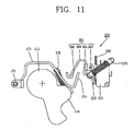
- the time delay output device 250 may include a switch 251 disposed to one side of the main shaft 111 to switch the fixed contactor and the movable contactor on or off, a delay member 261 disposed between the main shaft 111 and the switch 251 so as to be rotatable by interworking with the rotation of the main shaft 111, and operating the switch 251 with a preset time delay after the fixed contactor and the movable contactor come in contact with each other, and a delay member spring 270 having one end connected to the delay member 261 such that it can apply an elastic force in a direction that the delay member 261 urged into contact with the switch 251 when the main shaft 111 is rotated in a closing direction and apply an elastic force to keep the delay member 261 spaced apart from the switch 251 when the main shaft 11 is rotated in an opening direction.
- the switch 251 is installed in the case 141, and the delay member 261 is rotatably installed at one side of the switch 251.
- a contactor 253 (refer to Fig. 11 ) is disposed at one side of the switch 251.
- a stopper 255 which restricts the rotation of the delay member 261 is formed at an upper region of the switch 251.
- the delay member spring 270 is connected to one side of the delay member 261.
- the delay member 261 may include a rotation shaft 263 disposed alongside of the main shaft 111, a first contact portion 265 extending to one end from the rotation shaft 263 to be contacted by the switch 251, and a second contact portion 268 extending to the other end from the rotation shaft 263 and rotated together with the first contact portion 265.
- the second contact portion 268 may include a rounded portion 266 such that it can smoothly come in contact with the curved end portion 174 of the reset plate 171 when the main shaft 111 is rotated in the opening direction.
- the curved end portion 174 is in contact with the rounded portion 266 to thereby restrict the rotation of the delay member 261.
- the curved end portion 174 is formed to be inclined with respect to the delay member 261. This is so configured as to always ensure a constant time delay.
- the reset plate 171 is rotated by an elastic urging force of the reset plate spring 178, which then contacts the curved end portion 174 with the rounded portion 266, resulting in rotating the delay member 261 in a direction of being spaced apart from the switch 251.
- the delay member spring 270 which applies the elastic force to rotate the delay member 261 is connected to one region of the delay member 261, namely, to the first contact portion 265.
- the delay member spring 270 applies an elastic force in a direction that the delay member 261 is urged into contact with the switch 251 when the main shaft 111 is at the closing position, while applying an elastic force in a direction such that the delay member 261 is kept spaced apart from the switch 251 because the delay member 261 is rotated by passing through the dead point of the delay member spring 270 when the main shaft 111 is at the opening position.
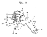
- an overcurrent relay interworking trip device 280 is installed at the rear side of the overcurrent relay 131 so as to allow the performing of the tripping operation, by which the fixed contactor and the movable contactor are separated from each other, by interworking with the detachment of the overcurrent relay 131.
- the overcurrent interworking trip device 280 may include a rotational shaft portion 283 rotatably installed at the trip device module 140, an operation arm 285 extending along a radial direction from one region of the rotational shaft portion 283 to be in contact with the overcurrent relay 131, a driving arm 287 extending from the other region of the rotational shaft portion 283 to be simultaneously rotated when the rotational shaft portion 283 is rotated, to accordingly press upon the driving protrusion 188 of the trip slider 181, by which the trip device module 140 is pressed upon to perform the tripping operation, and an elastic member 289 for applying an elastic force in a direction that the operation arm 285 is urged into contact with the overcurrent relay 131.
- the rotational shaft portion 283 is rotatably installed at the front surface of the case 141 of the trip device module 140 in a widthwise direction of the case 141.
- the operation arm 285 which is protruded in a radial direction of the rotational shaft portion 283 to be in contact with the overcurrent relay 131 is rotatably formed at one region of the rotational shaft portion 283.
- the driving arm 287 is formed at the other region of the rotational shaft portion 283. The driving arm 287 is in contact with the trip slider 181 to allow the trip slider 181 to be moved to the trip position.
- the driving arm 287 extends to be in contact with the driving protrusion 188 of the trip slider 181 to thusly press upon the trip slider 181.
- the elastic member 289 is disposed at the rotational shaft portion 283 to apply an elastic force in a direction such that the rotational shaft portion 283 comes in contact with the overcurrent relay 131.
- the elastic member 289 accumulates an elastic force when the overcurrent relay 131 is attached, and rotates the driving arm 287 by the accumulated elastic force when the overcurrent relay 131 is detached. Accordingly, the trip slider 181 is moved to the trip position, by which the movement of the switching mechanism 117 is operated to perform the tripping operation.
- a PCB (Printed Circuit Board) 144 connected to the overcurrent relay 131 is fixed to a lower region in the case 141 by screws 147.
- the PCB 144 is provided with a connector 145 for being connected to the overcurrent relay 131 (refer to Fig. 5 ).
- the trip signal output device 290 interworks with the actuator 161 operated when the overcurrent relay 131 outputs a trip command to externally display that the actuator 161 has performed the trip operation.
- the trip signal output device 290 of the trip device module 140 may include a switch 293 for outputting a signal upon being contacted, and an interworking member 313 contacted by the switch 293 when the trip slider 181 is at the trip position.
- the switch 293 is receivably installed at one side of the actuator 161 in the case 141, and contactors 295 which are contacted upon being pressed upon are formed at one side of the switch 293.
- the interworking member 313 may include a rotational shaft 315 at its center, and two arm portions 317 extending in different directions from the rotational shaft 315. The two arm portions 317 respectively extend toward the switch 293 and toward the trip slider 181.
- a contact piece 319 is disposed between the contactors 295 and the interworking member 313 to uniformly press upon the contactors 295.
- a pressing rod 187 extends at the trip slider 181 to press upon the arm portion 317 of the interworking member 313 for rotation when the trip slider 181 is moved to the trip position.
- a reset unit 320 is installed at one side of the case 141 to reset the trip signal output device 290 to its initial position.
- the reset unit 320 of the trip signal output device 290 may include a reset arm 321 disposed at one side of the pressing slider 191 to be rotatable between the trip position and the closing position so as to move the pressing slider 191 to the closing position, and a reset rod 331 protruded by interworking with the reset arm 321 to be exposed from one side of the overcurrent relay 131 to the exterior, and resetting the reset arm 321 to the closing position upon being pressed.
- the reset arm 321 may include a rotational shaft 323 at its central portion, and two arm portions 325 respectively extending in different directions from each other. Circlips 327 and a washer 328 for coupling the reset arm 321 are coupled to the rotational shaft 323.
- a front end portion of the reset rod 331 extends forwardly from the circuit breaker main body 110.
- a reset rod spring 337 is provided at the reset rod 331 to apply an elastic force such that the reset rod 331 can be moved toward the reset arm 321.
- a reset button 335 is provided at the front end portion of the reset rod 331 so as to operate the reset rod 331 in a pressing manner.
- the reset arm 321 may be configured to be operated by a motor.
- the front end portion of the reset arm 331 may be configured to be directly exposed externally.
- the actuator 161 when the overcurrent relay 131 outputs a trip command, the actuator 161 generates a magnetic force as power is applied to the stator 162, and the mover 165 is protruded by the magnetic force.
- the operation portion 167 interworks to be moved to the trip position.
- the latch member 211 is pressed by the operation portion 167 to be rotated to the release position.
- the pressing slider 191 When the latch member 211 is rotated, the pressing slider 191 is moved to the trip position by the elastic force of the pressing slider spring 197. Accordingly, the trip slider 181 is pressed to be moved to the trip position. The movement of the trip slider 181 to the trip position releases the switching mechanism 117 from being restricted by being contacted with the trip slider 181. The switching mechanism 117 then performs the tripping operation, which makes the main shaft 111 be rotated to the trip position. Accordingly, the fixed contactor and the movable contactor are separated from each other. Meanwhile, when the trip slider 181 is moved to the trip position, the interworking member 313 contacted by the pressing rod 187 is pressed to be rotated centering around the rotational shaft 315. The rotated interworking member 313 presses upon the contact piece 319. The pressed contact piece 319 comes into contact with the contactors 295 of the switch 293. The switch 293 then outputs a trip signal.
- the reset plate 171 When the main shaft 111 is rotated to the trip position, the reset plate 171 is rotated to the trip position by the reset plate driving arm 114. According to the rotation of the reset plate 171, the slider 231 is slid by being pressed upon by the reset plate 171. Then, the reset arm 238 is rotated by being pressed upon by the reset pin 235 of the slider 231. The rotated reset arm 238 presses the mover 165 so as to reset the actuator 161 to its initial position.
- the mover 165 is reset to its initial position, the reset arm 238 is rotated no more, which stops the reset pin 235 of the slider 231. In this state, if the housing 233 is pressed upon to be moved forwardly, the smoothing member 237 is compressed to perform a smoothing function.
- the reset plate 171 When the reset plate 171 is rotated to the trip position, the reset plate 171 is contacted by the operation portion 167 of the actuator 161. Accordingly, the operation portion 167 is reset to its initial position.
- the trip slider 181 is restricted by the pressing slider 191, the trip slider 181 is located at the trip position so as to prevent reclosing of the trip slider.
- the user presses the reset button 335 to rotate the reset arm 321 to the closing position by the reset rod 331.
- the reset arm 321 is rotated to the closing position, the pressing slider 191 contacted by the reset arm 321 is pulled up to be moved to the closing position.
- the latch member 211 is rotated to the closing position by the elastic urging force of the latch member spring 219.
- the pressing slider 191 is fixed into the closing position, and the trip slider 181 coming in contact with the latch member 211 is pressed upon by the latch member 211 to be moved to the closing position, thereby being in a state that it can be tripped.
- the reset plate 171 While the reset plate 171 is rotated to the trip position, the curved end portion 174 presses upon the delay member 261 of the time delay output device 250. The delay member 261 is then rotated in a direction of being spaced apart from the switch 293. Here, the delay member spring 270 passes through the dead point. Accordingly, the delay member 261 applies an elastic urging force toward a direction of being spaced apart from the switch 251.
- the reset plate 171 is rotated to the closing position due to the rotation of the main shaft 111 to the closing position, the reset plate 171 is rotated to the closing position by the elastic force of the reset plate spring 178.
- the curved end portion 174 of the reset plate 171 presses upon the first contactor 265 such that the delay member 261 is contacted by the contactor 253 of the switch 251 with the preset time delay after the fixed contactor comes in contact with the movable contactor so as to allow the switch 251 to output a sense signal to the exterior.
- the switch 251 outputs the signal.
- the delay member 261 is rotated by an external force or the like in a direction to be close to the switch 251, the delay member 261 is restricted from being rotated due to the contact between the rounded portion 266 and the curved end portion 174.
- the reset plate 171 When the main shaft 111 is rotated to the closing position, the reset plate 171 is rotated in a clockwise direction (in the drawing) by the elastic force of the reset plate spring 178. The curved end portion 174 of the reset plate 171 then presses the rounded portion 266 of the second contact portion 268 upwardly (in the drawing) so as to allow the delay member 261 to be rotated in a direction farther away from the switch 251.
- the delay member 261 is rotated such that the delay member spring 270 passes through the dead point and thereby the elastic force of the delay member spring 270 is applied in a direction such that the delay member 261 is spaced apart from the switch 251.
- the curved end portion 174 of the reset plate 171 rotated via the rounded portion 266 is continuously rotated to press upon the first contact portion 265, thereby rotating the delay member 261 to be passed through the dead point. Accordingly, the switch 251 is allowed to always output a signal with a constant time delay after the fixed contactor comes in contact with the movable contactor.
- the delay member 261 is kept rotated by the elastic urging force of the delay member spring 270, and accordingly the first contact portion 265 is brought into contact with the contactor 253 of the switch 251.
- the switch 251 then outputs a signal to the exterior when the first contact portion 265 comes in contact with the contactor 253.
- the operation arm 285, the rotational shaft portion 283 and the driving arm 287 are simultaneously rotated by the accumulated elastic force of the elastic member 289.
- the driving arm 287 is rotated, the driving protrusion 188 is pressed upon such that the trip slider 181 is moved down along the case 141.
- the part of the switching mechanism 117 contacted by the trip slider 181 is pressed upon so as to release the restricted switching mechanism 117. Accordingly, the switching mechanism 117 performs the tripping operation.
- the present invention provides a trip device module which is capable of being commonly used for devices with different inter-phase spacings and a circuit breaker implementing the same.
- the present invention upon outputting a trip command, components which interwork with the operation of an actuator and a main shaft are disposed in one case to thusly interwork together. Therefore, a compact configuration and reliable operations can be ensured for the trip device module and a circuit breaker having the same, as compared to the related art where the separate fabrication of each component incurs an increase in the number of components and the size, a requirement of a device for making the separate components interwork together, a degradation in operational reliability, and an increase in an overall size of the device due to an installation space required.
- the present invention provides a trip device module which is capable of preventing an electric shock and damage to components due to non-performance of a trip operation by allowing the trip operation to be uniformly performed without depending upon an operator's determination when detaching the overcurrent relay, and a circuit breaker having the same.
- the present invention provides a trip device module which is capable of preventing malfunction due to the vibration of mass due to an electric repulsive force or the like and of enhancing reliability by using a spring instead of using a mass, and a circuit breaker having the same.
- the present invention provides a trip device module which is capable of preventing damage to components by allowing an actuator to be reset such that a great force of a main shaft cannot be directly applied to the actuator, and a circuit breaker having the same.
- the present invention also provides a trip device module which is capable of avoiding the use of a separate circuit for maintaining a trip signal by allowing a constant output of the trip signal by an interworking with the trip device module, and a circuit breaker having the same.
- the present invention provides a trip device module allowing a quick action upon a fault by enabling a user to immediately detect a tripped state where an actuator has already performed a tripping operation in the case where a reset button or reset rod is protruded forwardly.
Claims (15)
- Un module de dispositif déclencheur (140) destiné à être disposé entre un relais de surcharge de courant et un mécanisme de commutation pour commuter à la fermeture ou à l'ouverture des contacteurs destinés à être connectés par le mécanisme de commutation et pour générer une force de manipulation lorsque le relais de surcharge de courant délivre en sortie un signal de déclenchement destiné à permettre au mécanisme de commutation d'effectuer une opération de déclenchement, caractérisé en ce que le module du dispositif déclencheur comprend :un boîtier (141) possédant un premier et un second logements de réception de bras (148, 149) en évidement dans celui-ci de manière à recevoir en les y logeant des bras d'entraînement disposés sur un arbre principal avec divers espacements différents entre les phases ;un actionneur (161) disposé dans le boîtier et possédant une partie de sortie extraite ou introduite dans celui-ci lorsque le relais de surcharge de courant délivre en sortie le signal de déclenchement ;une plaque de réarmement (171) installée dans le boîtier de manière à interagir avec l'arbre principal (111) afin d'initialiser la partie de sortie de l'actionneur ; etun coulisseau déclencheur (181) configuré pour permettre au mécanisme de commutation d'effectuer l'opération de déclenchement lorsque l'actionneur effectue une opération de déclenchement.
- Le module de la revendication 1, dans lequel les bras d'entraînement comprennent un bras d'entraînement de plaque de réarmement contre lequel la plaque de réarmement vient en contact et des bras d'entraînement de contacteurs mobiles reliés au contacteur mobile, dans lequel le bras d'entraînement de la plaque de réarmement se place dans le premier logement de réception de bras et les bras d'entraînement de contacteurs mobiles se placent dans le second logement de réception de bras.
- Le module de la revendication 1, dans lequel les bras d'entraînement sont reliés au contacteur mobile et viennent également en contact avec la plaque de réarmement, et viennent se placer dans le premier logement de réception de bras.
- Le module de la revendication 1, comprenant en outre une unité de réarmement d'actionneur interagissant avec la plaque de réarmement afin de réarmer l'actionneur à sa position initiale.
- Le module de la revendication 4, dans lequel l'unité de réarmement de l'actionneur comprend :un coulisseau disposé d'un côté de la plaque de réarmement de manière à être déplacé en pressant dessus lorsque la plaque de réarmement est entraînée en rotation ; etun bras de réarmement possédant une extrémité sur laquelle le coulisseau vient en contact de manière à être entraîné en rotation et un autre côté venant appuyer sur la pièce d'entraînement de l'actionneur pour réarmer l'actionneur à sa position initiale.
- Le module de la revendication 5, dans lequel l'unité de réarmement d'actionneur comprend en outre un élément amortisseur disposé entre la plaque de réarmement et la pièce actionnement de l'actionneur et comprimé après que la pièce d'actionnement de l'actionneur soit réarmée à sa position initiale.
- Le module de la revendication 1 ou 4, comprenant en outre un dispositif de sortie temporisateur interagissant avec l'arbre principal de manière à délivrer un signal avec temporisation prédéterminée après que le contacteur fixe et le contacteur mobile soient venus en contact l'un avec l'autre.
- Le module de la revendication 7, dans lequel le dispositif de sortie à temporisateur comprend :un commutateur disposé d'un côté de l'arbre principal ;un organe à retard disposé entre l'arbre principal et le commutateur de manière à ce qu'il puisse être entraîné en rotation par interaction avec la rotation de l'arbre principal, et configuré pour actionner le commutateur avec une temporisation prédéterminée après que le contacteur fixe et que le contacteur mobile soient venus en contact l'un avec l'autre ; etun ressort d'organe à retard possédant une extrémité reliée à l'organe de retard de manière à appliquer une force élastique dans une direction telle que l'organe à retard vienne en contact avec le commutateur lorsque l'arbre principal est entraîné en rotation dans une direction de fermeture, et pour appliquer une force élastique dans une direction telle que l'organe à retard soit maintenu à distance du commutateur lorsque l'arbre principal est entraîné en rotation dans une direction d'ouverture.
- Le module de la revendication 1 ou 7, comprenant en outre un dispositif déclencheur en relation d'interaction avec le relais de surcharge de courant, interagissant avec la séparation du relais de surcharge de courant afin de permettre au mécanisme de commutation d'être déclenché.
- Le module de la revendication 9, dans lequel le dispositif de déclenchement d'interaction de relais de surcharge de courant comprend :une partie d'arbre de rotation installée à rotation à l'endroit du module de dispositif déclencheur ;un bras d'actionnement s'étendant dans une direction radiale à partir d'une région de la partie d'arbre de rotation de manière à être en contact avec le relais de surcharge de courant ;un bras d'entraînement s'étendant à partir d'une autre région de la partie d'arbre de rotation afin de pouvoir être entraîné simultanément en rotation avec la partie d'arbre de rotation, venant ainsi appuyer contre le module de dispositif déclencheur pour effectuer l'opération de déclenchement ; etun organe élastique configuré pour appliquer une force élastique dans une direction telle que le bras d'actionnement soit sollicité jusqu'au contact du relais de surcharge de courant.
- Le module de la revendication 1 ou 9, comprenant en outre un dispositif de sortie de signal de déclenchement interagissant avec l'actionneur de manière à délivrer en sortie un signal de déclenchement vers l'extérieur lorsque l'actionneur exécute l'opération de déclenchement.
- Le module de la revendication 11, dans lequel le dispositif de sortie de signal de déclenchement comprend :un commutateur configuré pour délivrer en sortie un signal lorsqu'il est mis en contact ; etun organe d'interaction interagissant avec le coulisseau de déclenchement pour venir en contact avec le commutateur lorsque le coulisseau de déclenchement est dans une position de déclenchement.
- Le module de la revendication 12, dans lequel le dispositif de sortie de signal de déclenchement comprend en outre une pièce de contact interposée entre l'organe d'interaction et le commutateur.
- Le module de la revendication 13, comprenant en outre une unité de réarmement configurée pour réarmer le dispositif de sortie de signal de déclenchement à sa position initiale.
- Le module de la revendication 14, comprenant en outre :un coulisseau presseur disposé à coulissement à une extrémité du coulisseau de déclenchement pour appuyer contre le coulisseau de déclenchement en direction d'une position de déclenchement ; etun ressort de coulisseau de déclenchement configuré pour appliquer une force élastique de manière à déplacer le coulisseau presseur en direction de la position de déclenchement ;dans lequel l'unité de réarmement comprend un bras de réarmement disposé d'un côté du coulisseau presseur de manière à pouvoir être entraîné en rotation entre la position de déclenchement et une position de fermeture, et configuré pour déplacer le coulisseau presseur vers la position de fermeture.
Applications Claiming Priority (4)
| Application Number | Priority Date | Filing Date | Title |
|---|---|---|---|
| KR1020070070279A KR100854387B1 (ko) | 2007-07-12 | 2007-07-12 | 트립기구모듈 및 이를 구비한 차단기 |
| KR1020070070276A KR100876411B1 (ko) | 2007-07-12 | 2007-07-12 | 차단기의 액츄에이터 리셋 장치 |
| KR1020070070280A KR100876413B1 (ko) | 2007-07-12 | 2007-07-12 | 과전류 계전기 연동 트립기능을 구비한 차단기 |
| KR1020070070282A KR100905019B1 (ko) | 2007-07-12 | 2007-07-12 | 트립신호 출력장치를 구비한 차단기 |
Publications (2)
| Publication Number | Publication Date |
|---|---|
| EP2015339A1 EP2015339A1 (fr) | 2009-01-14 |
| EP2015339B1 true EP2015339B1 (fr) | 2010-06-02 |
Family
ID=39885076
Family Applications (1)
| Application Number | Title | Priority Date | Filing Date |
|---|---|---|---|
| EP08011708A Active EP2015339B1 (fr) | 2007-07-12 | 2008-06-27 | Module de déclenchement et disjoncteur comprenant ce module |
Country Status (4)
| Country | Link |
|---|---|
| EP (1) | EP2015339B1 (fr) |
| DE (1) | DE602008001408D1 (fr) |
| ES (1) | ES2344583T3 (fr) |
| MY (1) | MY143458A (fr) |
Families Citing this family (3)
| Publication number | Priority date | Publication date | Assignee | Title |
|---|---|---|---|---|
| KR101212213B1 (ko) | 2011-07-15 | 2012-12-13 | 엘에스산전 주식회사 | 회로차단기의 모듈화된 트립기구 및 부속기구 장치 |
| CN104810220B (zh) * | 2015-05-15 | 2016-09-28 | 宁波市士鑫电器有限公司 | 一种三相电机的缺相保护开关及其使用方法 |
| KR101759601B1 (ko) * | 2015-12-28 | 2017-07-31 | 엘에스산전 주식회사 | 기중 차단기용 지연시간 발생장치 |
Family Cites Families (2)
| Publication number | Priority date | Publication date | Assignee | Title |
|---|---|---|---|---|
| FR2624650B1 (fr) * | 1987-12-10 | 1990-04-06 | Merlin Gerin | Disjoncteur multipolaire a boitier moule de calibre eleve |
| US5705968A (en) * | 1996-05-14 | 1998-01-06 | Eaton Corporation | Trip bar with adjustable latch load for electrical switching apparatus |
-
2008
- 2008-06-27 EP EP08011708A patent/EP2015339B1/fr active Active
- 2008-06-27 DE DE602008001408T patent/DE602008001408D1/de active Active
- 2008-06-27 ES ES08011708T patent/ES2344583T3/es active Active
- 2008-07-08 MY MYPI20082523A patent/MY143458A/en unknown
Also Published As
| Publication number | Publication date |
|---|---|
| MY143458A (en) | 2011-05-13 |
| EP2015339A1 (fr) | 2009-01-14 |
| DE602008001408D1 (de) | 2010-07-15 |
| ES2344583T3 (es) | 2010-08-31 |
Similar Documents
| Publication | Publication Date | Title |
|---|---|---|
| KR100854387B1 (ko) | 트립기구모듈 및 이를 구비한 차단기 | |
| RU2378730C1 (ru) | Воздушный выключатель с механизмом индикации механического размыкания | |
| US10410810B2 (en) | Switching device for LV electric installations | |
| US9928977B2 (en) | Electrical switching apparatus, and operating handle assembly and trip cam therefor | |
| EP2015340A2 (fr) | Appareil de sortie de temporisation pour disjoncteur | |
| CN109698099A (zh) | 一种断路器 | |
| EP2015339B1 (fr) | Module de déclenchement et disjoncteur comprenant ce module | |
| CN101345166B (zh) | 脱扣装置模块及实现脱扣装置模块的断路器 | |
| CN106796849B (zh) | 电气开关设备及其对应的传动总成 | |
| KR100905019B1 (ko) | 트립신호 출력장치를 구비한 차단기 | |
| KR101015276B1 (ko) | 탄성가압유닛 및 이를 구비한 배선용 차단기 | |
| EP3392898B1 (fr) | Dispositif de déclenchement magnétique d'un disjoncteur à air | |
| KR100876413B1 (ko) | 과전류 계전기 연동 트립기능을 구비한 차단기 | |
| JP4128897B2 (ja) | 漏電遮断器 | |
| RU2378731C1 (ru) | Размыкающий модуль и автоматический выключатель с таким модулем | |
| CN107004542B (zh) | 电气开关设备以及用于其上的杆轴卡持组件 | |
| KR100379691B1 (ko) | 회로차단기의 접점개폐장치 | |
| CN220233067U (zh) | 脱扣机构及断路器 | |
| KR200398043Y1 (ko) | 마그네틱 트립 디바이스 | |
| CN104752113B (zh) | 一种电压电器电开关 | |
| CN114078668A (zh) | 断路器 | |
| JP2023094072A (ja) | 回路遮断器 | |
| KR100493401B1 (ko) | 회로차단기용 부속장치의 트립기구 구동장치 | |
| KR200411516Y1 (ko) | 수동 리셋 조작부를 구비한 마그네틱 트립 디바이스 | |
| EP3346483A1 (fr) | Dispositif de déclenchement magnétique de disjoncteur |
Legal Events
| Date | Code | Title | Description |
|---|---|---|---|
| PUAI | Public reference made under article 153(3) epc to a published international application that has entered the european phase |
Free format text: ORIGINAL CODE: 0009012 |
|
| 17P | Request for examination filed |
Effective date: 20080627 |
|
| AK | Designated contracting states |
Kind code of ref document: A1 Designated state(s): AT BE BG CH CY CZ DE DK EE ES FI FR GB GR HR HU IE IS IT LI LT LU LV MC MT NL NO PL PT RO SE SI SK TR |
|
| AX | Request for extension of the european patent |
Extension state: AL BA MK RS |
|
| AKX | Designation fees paid |
Designated state(s): DE ES FR GB IT |
|
| GRAP | Despatch of communication of intention to grant a patent |
Free format text: ORIGINAL CODE: EPIDOSNIGR1 |
|
| GRAS | Grant fee paid |
Free format text: ORIGINAL CODE: EPIDOSNIGR3 |
|
| GRAA | (expected) grant |
Free format text: ORIGINAL CODE: 0009210 |
|
| AK | Designated contracting states |
Kind code of ref document: B1 Designated state(s): DE ES FR GB IT |
|
| REG | Reference to a national code |
Ref country code: GB Ref legal event code: FG4D |
|
| REF | Corresponds to: |
Ref document number: 602008001408 Country of ref document: DE Date of ref document: 20100715 Kind code of ref document: P |
|
| REG | Reference to a national code |
Ref country code: ES Ref legal event code: FG2A Ref document number: 2344583 Country of ref document: ES Kind code of ref document: T3 |
|
| PLBE | No opposition filed within time limit |
Free format text: ORIGINAL CODE: 0009261 |
|
| STAA | Information on the status of an ep patent application or granted ep patent |
Free format text: STATUS: NO OPPOSITION FILED WITHIN TIME LIMIT |
|
| 26N | No opposition filed |
Effective date: 20110303 |
|
| REG | Reference to a national code |
Ref country code: DE Ref legal event code: R097 Ref document number: 602008001408 Country of ref document: DE Effective date: 20110302 |
|
| REG | Reference to a national code |
Ref country code: FR Ref legal event code: PLFP Year of fee payment: 9 |
|
| REG | Reference to a national code |
Ref country code: FR Ref legal event code: PLFP Year of fee payment: 10 |
|
| REG | Reference to a national code |
Ref country code: FR Ref legal event code: PLFP Year of fee payment: 11 |
|
| PGFP | Annual fee paid to national office [announced via postgrant information from national office to epo] |
Ref country code: GB Payment date: 20200408 Year of fee payment: 13 |
|
| GBPC | Gb: european patent ceased through non-payment of renewal fee |
Effective date: 20210627 |
|
| PG25 | Lapsed in a contracting state [announced via postgrant information from national office to epo] |
Ref country code: GB Free format text: LAPSE BECAUSE OF NON-PAYMENT OF DUE FEES Effective date: 20210627 |
|
| PGFP | Annual fee paid to national office [announced via postgrant information from national office to epo] |
Ref country code: FR Payment date: 20230306 Year of fee payment: 16 |
|
| PGFP | Annual fee paid to national office [announced via postgrant information from national office to epo] |
Ref country code: IT Payment date: 20230309 Year of fee payment: 16 |
|
| PGFP | Annual fee paid to national office [announced via postgrant information from national office to epo] |
Ref country code: DE Payment date: 20230306 Year of fee payment: 16 |
|
| P01 | Opt-out of the competence of the unified patent court (upc) registered |
Effective date: 20230625 |
|
| PGFP | Annual fee paid to national office [announced via postgrant information from national office to epo] |
Ref country code: ES Payment date: 20230714 Year of fee payment: 16 |