EP2015339B1 - Trip device module and circuit breaker implementing the same - Google Patents
Trip device module and circuit breaker implementing the same Download PDFInfo
- Publication number
- EP2015339B1 EP2015339B1 EP08011708A EP08011708A EP2015339B1 EP 2015339 B1 EP2015339 B1 EP 2015339B1 EP 08011708 A EP08011708 A EP 08011708A EP 08011708 A EP08011708 A EP 08011708A EP 2015339 B1 EP2015339 B1 EP 2015339B1
- Authority
- EP
- European Patent Office
- Prior art keywords
- trip
- reset
- actuator
- slider
- module
- Prior art date
- Legal status (The legal status is an assumption and is not a legal conclusion. Google has not performed a legal analysis and makes no representation as to the accuracy of the status listed.)
- Active
Links
Images


Classifications
-
- H—ELECTRICITY
- H01—ELECTRIC ELEMENTS
- H01H—ELECTRIC SWITCHES; RELAYS; SELECTORS; EMERGENCY PROTECTIVE DEVICES
- H01H71/00—Details of the protective switches or relays covered by groups H01H73/00 - H01H83/00
- H01H71/10—Operating or release mechanisms
- H01H71/1045—Multiple circuits-breaker, e.g. for the purpose of dividing current or potential drop
-
- H—ELECTRICITY
- H01—ELECTRIC ELEMENTS
- H01H—ELECTRIC SWITCHES; RELAYS; SELECTORS; EMERGENCY PROTECTIVE DEVICES
- H01H71/00—Details of the protective switches or relays covered by groups H01H73/00 - H01H83/00
- H01H71/10—Operating or release mechanisms
- H01H71/12—Automatic release mechanisms with or without manual release
- H01H71/44—Automatic release mechanisms with or without manual release having means for introducing a predetermined time delay
-
- H—ELECTRICITY
- H01—ELECTRIC ELEMENTS
- H01H—ELECTRIC SWITCHES; RELAYS; SELECTORS; EMERGENCY PROTECTIVE DEVICES
- H01H71/00—Details of the protective switches or relays covered by groups H01H73/00 - H01H83/00
- H01H71/10—Operating or release mechanisms
- H01H71/50—Manual reset mechanisms which may be also used for manual release
- H01H71/505—Latching devices between operating and release mechanism
-
- H—ELECTRICITY
- H01—ELECTRIC ELEMENTS
- H01H—ELECTRIC SWITCHES; RELAYS; SELECTORS; EMERGENCY PROTECTIVE DEVICES
- H01H71/00—Details of the protective switches or relays covered by groups H01H73/00 - H01H83/00
- H01H71/10—Operating or release mechanisms
- H01H71/50—Manual reset mechanisms which may be also used for manual release
- H01H71/58—Manual reset mechanisms which may be also used for manual release actuated by push-button, pull-knob, or slide
-
- H—ELECTRICITY
- H01—ELECTRIC ELEMENTS
- H01H—ELECTRIC SWITCHES; RELAYS; SELECTORS; EMERGENCY PROTECTIVE DEVICES
- H01H73/00—Protective overload circuit-breaking switches in which excess current opens the contacts by automatic release of mechanical energy stored by previous operation of a hand reset mechanism
- H01H73/36—Protective overload circuit-breaking switches in which excess current opens the contacts by automatic release of mechanical energy stored by previous operation of a hand reset mechanism having electromagnetic release and no other automatic release
- H01H73/44—Protective overload circuit-breaking switches in which excess current opens the contacts by automatic release of mechanical energy stored by previous operation of a hand reset mechanism having electromagnetic release and no other automatic release reset by push-button, pull-knob or slide
Description
- The present invention relates to a trip device module and a circuit breaker implementing the same, and particularly, to a trip device module which is usable in devices having different spacings between the phases, and to a circuit breaker implementing the same.
- A so-called circuit breaker refers to an electric protection apparatus which is installed between an electrical power source and load equipment in order to protect the load equipment and a supply line from a fault current (a short circuit, excess current due to an earth fault, etc.) which may occur in an electrical circuit.
- A circuit breaker includes a switching mechanism for switching a fixed contactor and a movable contactor, an overcurrent relay for detecting a fault current and outputting a trip command so as to block the conducting of excess current, and a trip device module disposed between the switching mechanism and the overcurrent relay for generating a mechanical manipulation force when the overcurrent relay outputs the trip command and transferring the mechanical manipulation force to the switching mechanism.
- Also, the circuit breaker includes other devices for executing additional functions, such as a trip alarming function for externally informing when a trip function of the trip device module is performed, and a time delay output function for allowing the excess current relay to perform an MCR (Making Current Release).
- However, in the related art circuit breaker, the different spacing between each phase (e.g., R, S T or N phase) according to the breaking capacity of each device makes it impossible to commonly use the trip device module.
- In addition, since the other devices for performing the additional functions, i.e., the trip alarming function and the time delay output function should be installed in a main body of the circuit breaker, the main body of the circuit breaker may be increased in size and a great deal of time and effort is required for their assembly. Furthermore, upon the synchronization or interworking with each device, it is difficult to enhance the operational reliability of the circuit breaker.
- Document
US 4 958 135 discloses a device according to the preamble ofclaim 1. - Therefore, to solve those problems of the related art, it is an object of the present invention to provide a trip device module which is usable in other devices having different spacings between the phases, and a circuit breaker adopting the same.
- It is another object of the present invention to provide a trip device module which is capable of implementing a compact configuration and enhancing operational reliability, and a circuit breaker adopting the same.
- To achieve these and other advantages and in accordance with the purpose of the present invention, as embodied and broadly described herein, there is provided a trip device module, which is adopted to be disposed between an overcurrent relay and a switching mechanism for switching on or off contactors to be connected to the switching mechanism and which generates a manipulation force when the overcurrent relay outputs a trip signal to allow the switching mechanism to perform a tripping operation, the trip device module including: a case having first and second arm receiving pockets to receive driving arms disposed at a main shaft with various different inter-phase spacings, an actuator received in the case and having an output portion drawn out or introduced thereinto when the overcurrent relay outputs the trip signal, a reset plate installed in the case to interwork with the main shaft so as to initialize the output portion of the actuator, and a trip slider configured to allow the switching mechanism to perform the tripping operation when the actuator performs a tripping operation.
- The driving arms may include a reset plate driving arm disposed to be contacted by the reset plate and movable contactor driving arms connected to the movable contactor. The reset plate driving arm may be received in the first arm receiving pocket and the movable contactor driving arms may be received in the second arm receiving pocket.
- The driving arms may be connected to the movable contactor as well as coming into contact with the reset plate, and be received in the first arm receiving pocket.
- The trip device module may further include an actuator reset unit for interworking with the reset plate to reset the actuator to its initial position.
- The actuator reset unit may include a slider disposed at one side of the reset plate to be movable by being pressed upon when the reset plate is rotated, and a reset arm having one side contacted by the slider so as to be rotated and the other side pressing upon the mover of the actuator so as to reset the actuator to its initial position.
- The slider may include a housing, and a reset pin protruding from the housing so as to be in contact with the reset arm.
- The actuator reset unit may further include a smoothing member disposed between the reset plate and the mover of the actuator and being compressed after the mover of the actuator is reset to its initial position.
- The trip device module may further include a time delay output device interworking with the main shaft to output a signal with a preset time delay after the fixed contactor and the movable contactor come into contact with each other.
- The time delay output device may include a switch disposed at one side of the main shaft, a delay member disposed between the main shaft and the switch to be rotated by interworking with the rotation of the main shaft and configured to operate the switch with a preset delay time after the fixed contactor and the movable contactor come into contact with each other, and a delay member spring having one end connected to the delay member so as to apply an elastic force in a direction such that the delay member is urged into contact with the switch when the main shaft is rotated in a closing direction, and to apply an elastic force in a direction such that the delay member is kept spaced apart from the switch when the main shaft is rotated in an opening direction.
- The trip device module may further include an overcurrent relay interworking trip device interworking with the detachment of the overcurrent relay to allow the switching mechanism to be tripped.
- The overcurrent relay interworking trip device may include a rotational shaft portion rotatably installed at the trip device module, an operation arm extending in a radial direction from one region of the rotational shaft portion to come into contact with the overcurrent relay, a driving arm extending from another region of the rotational shaft portion so as to be rotated simultaneously with the rotational shaft portion for thereby pressing upon the trip device module to perform the trip operation, and an elastic member configured to apply an elastic force in a direction such that the operation arm is urged into contact with the overcurrent relay.
- The trip slider may be provided with a driving protrusion protruding to come into contact with the driving arm.
- A guiding portion may be formed in the case to guide the overcurrent relay.
- The trip device module may further include a trip signal output device interworking with the actuator to output a trip signal to the exterior when the actuator performs the trip operation.
- The trip signal output device may include a switch configured to output a signal upon being contacted, and an interworking member interworking with the trip slider to come into contact with the switch when the trip slider is at a trip position.
- The trip signal output device may further include a contact piece interposed between the interworking member and the switch.
- The trip device module may further include a reset unit configured to reset the trip signal output device to its initial position.
- The trip device module may further comprise a pressing slider slidably disposed at one side of the trip slider to press the trip slider towards a trip position, and a trip slider spring configured to apply an elastic force so as to move the pressing slider towards the trip position, wherein the reset unit may include a reset arm disposed at one side of the pressing slider to be rotatable between the trip position and a closing position, and configured to move the pressing slider to the closing position.
- The trip device module may further include a latch member rotatable between a fixing position of fixing the pressing slider to the closing position and a release position of releasing the fixed pressing slider, and a latch member spring configured to apply an elastic member such that the latch member is rotated towards the fixing position, wherein the trip slider may be reset to the closing position by the latch member when the pressing slider is at the trip position.
- The reset unit may further include a reset rod protruded by interworking with the reset arm to be exposed from one side of the overcurrent relay to the exterior, and resetting the reset arm to the closing position upon being pressed.
- The reset unit may further include a reset rod spring configured to apply an elastic force such that the reset rod is moved toward the reset arm.
- The reset unit may further include a reset button installed to have one region thereof exposed to the outside and another region thereof coupled to the reset rod.
- The trip device module may further include a time delay output device interworking with the main shaft to output a signal with a preset time delay after the fixed contactor comes into contact with the movable contactor, an overcurrent relay interworking trip device interworking with the detachment of the overcurrent relay to allow the switching mechanism to be tripped, and a trip signal output device interworking with the actuator to output a trip signal to the exterior when the actuator performs the trip operation.
- A circuit breaker implementing such a trip device module may include a circuit breaker main body including a fixed contactor and a movable contactor, a main shaft, and a switching mechanism interworking with the main shaft and the movable contactor to switch on or off the fixed contactor and the movable contactor, an overcurrent relay coupled to the main body of the circuit breaker to detect a fault current, and the aforesaid trip device module interposed between the overcurrent relay and the switching mechanism.
- The circuit breaker may further include an actuator reset unit interworking with the reset plate to reset the actuator to its initial position.
- The circuit breaker may further include a time delay output device interworking with the main shaft to output a signal with a preset time delay after the fixed contactor comes in contact with the movable contactor.
- The circuit breaker may further include an overcurrent relay interworking trip device interworking with the detachment of the overcurrent relay to allow the switching mechanism to be tripped.
- The circuit breaker may further include a trip signal output device interworking with the actuator to output a trip signal to the exterior when the actuator performs a trip operation.
- The circuit breaker may further include a time delay output device interworking with the main shaft to output a signal with a preset time delay after the fixed contactor comes in contact with the movable contactor, an overcurrent relay interworking trip device interworking with the detachment of the overcurrent relay to allow the switching mechanism to be tripped, and a trip signal output device interworking with the actuator to output a trip signal to the exterior when the actuator performs a trip operation.
- The foregoing and other objects, features, aspects and advantages of the present invention will become more apparent from the following detailed description of the present invention when taken in conjunction with the accompanying drawings.
- The accompanying drawings, which are included to provide a further understanding of the invention and are incorporated in and constitute a part of this specification, illustrate embodiments of the invention and together with the description serve to explain the principles of the invention.
- In the drawings:
-
Figure 1 is a perspective view showing the exterior of a circuit breaker having a trip device module in accordance with one embodiment of the present invention; -
Figure 2 is a perspective view of the interior of the circuit breaker ofFigure 1 ; -
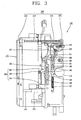
Figure 3 is a side view showing an installed state of the trip device module ofFigure 1 ; -
Figure 4 is a perspective view of the trip device module ofFigure 1 ; -
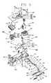
Figure 5 is a perspective exploded view of the trip device module ofFigure 1 ; -
Figure 6 and 7 are perspective views respectively showing a usage state of the trip device module ofFigure 3 ; -
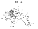
Figure 8 is a perspective view showing an area of an actuator ofFigure 3 ; -
Figure 9 is a side view of the actuatorFigure 8 ; -
Figure 10 is a schematic view for describing an operation of the actuator ofFigure 8 ; -
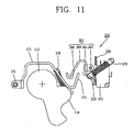
Figure 11 is a side view showing a time delay output device of the trip device module ofFigure 5 ; -
Figure 12 is a perspective view showing a coupled state of the time delay output device ofFigure 11 ; -
Figure 13 is a front view showing an overcurrent relay interworking trip device of the trip device module ofFigure 3 ; -
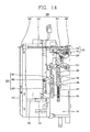
Figure 14 is a side view showing a trip position of a trip signal output device ofFigure 3 ; -
Figure 15 is a side view for describing the operation of the overcurrent relay interworking trip device ofFigure 13 ; and -
Figure 16 is a front view showing an installed state of the trip signal output device of the trip device module ofFigure 2 . - Description will now be given in detail of a trip device module and a circuit breaker implementing the same according to the present invention, with reference to the accompanying drawings.
- As shown in
Figs. 1 to 3 , the circuit breaker having the trip device module may include amain body 110 disposing a fixed contactor and a movable contactor therein, amain shaft 111, and aswitching mechanism 117 interposed between the movable contactor and themain shaft 111 to switch the fixed contactor and the movable contactor on or off, afront surface cover 120 coupled onto the front surface of themain body 110, anovercurrent relay 131 coupled to thefront surface cover 120 such that its front surface can be exposed and for detecting a fault current and outputting a trip signal (command), and atrip device module 140 having anactuator 161 which generates a manipulation force when theovercurrent relay 131 outputs the trip signal so as to be couplable to themain shaft 111 having different inter-phase spacings. - An
opening 122 is formed in thefront surface cover 120 to expose theovercurrent relay 131 to the exterior. Atrip button 125 and aclosing button 126 are respectively provided at thefront surface cover 120 so as to manually switch theswitching mechanism 117 on or off. - The
trip device module 140 is installed at the rear side of theovercurrent relay 131. Theswitching mechanism 117 is disposed at one side of thetrip device module 140 to thusly perform a tripping operation of the fixed contactor and the movable contactor according to the trip command upon detecting a fault current of theovercurrent relay 131. - As shown in
Figs. 4 and5 , thetrip device module 140 may include acase 141 having first and secondarm receiving pockets 148 and 149 (refer toFigs. 6 and 7 ) recessed and sized so as to accommodatingly receive driving arms disposed themain shaft 111 with various inter-phase spacings, anactuator 161 received in thecase 141 to generate a manipulation force when theovercurrent relay 131 outputs the trip signal, areset plate 171 installed in thecase 141 to interwork with themain shaft 111 so as to initialize an output portion of theactuator 161, and atrip slider 181 slidable along thecase 141 and connected to theswitching mechanism 117 so as to allow the tripping operation of theswitching mechanism 117 when theactuator 161 performs a tripping operation. - The
trip device module 140 may further include a timedelay output device 250 interworking with themain shaft 111 to output a signal with a preset time delay after the fixed contactor comes in contact with the movable contactor, an overcurrent relayinterworking trip device 280 interworking with the detaching of theovercurrent relay 131 to allow the switching mechanism 1117 to be tripped, and a tripsignal output device 290 interworking with theactuator 161 to output a trip signal to the exterior when theactuator 161 performs the trip operation. - The
case 141 may include a casemain body 142a having an opened receiving space therein and having an opening at its front side, and acase cover 142b for being integrally fixed to the casemain body 142a byplural screws 143 so as to close the opening at the front side of the casemain body 142a. - The case
main body 142a may be provided with guidingportions 150 to slidably guide theovercurrent relay 131 when theovercurrent relay 131 is detached. Rails 133 (refer toFig. 14 ) are respectively disposed at both side surfaces of theovercurrent relay 131 to be slidably received in the guidingportions 150. - The
main shaft 111 may include a plurality of movable contactor driving arms for driving the movable contactor of each phase spaced apart from each other to have different inter-phase spacings, and a switching mechanism driving arm connected to theswitching mechanism 117. As shown inFig. 6 , a plurality of movablecontactor driving arms 113 with a relatively short inter-phase spacing L1 are arranged at intervals along a firstmain shaft 112a having a relatively small capacity (e.g., 2000A). As shown inFig. 7 , a plurality of movablecontactor driving arms 113 with a relatively long inter-phase distance L2 are arranged at intervals along a secondmain shaft 112a having a relatively greater capacity (e.g., 4000A). - Also, the second
main shaft 112b is configured such that a resetplate driving arm 114 is spaced apart from the movablecontactor driving arms 113 due to its relatively long inter-phase spacing. The firstmain shaft 112a may not separately have any reset plate driving arm because the movablecontactor driving arms 113 drive the movable contactor and thereset plate 171. Therefore, the secondarm receiving pocket 149 exists as an empty space. Hereinafter, the firstmain shaft 112a (hereinafter, called the main shaft 111) at which the reset plate driving arm and the movable contactor driving arms are integrated with each other will be exemplarily described. - The
actuator 161 which generates a manipulation force when theovercurrent relay 131 outputs the trip command and thereset plate 171 rotated by interworking with themain shaft 111 to reset an operation portion of theactuator 161 are installed in thecase 141. - As shown in
Figs. 8 to 10 , theactuator 161 may include astator 162 which generates a magnetic force when power is applied thereto, amover 165 protruded by the magnetic force of thestator 162, and aspring 169 which applies an elastic force in a direction such that themover 165 is urged to be protruded. Thestator 162 may include acase 163 and acoil 164 disposed inside thecase 163. Anoperation portion 167 interworking with themover 165 is installed at one end of theactuator 161. Theoperation portion 167 is composed of two parts, which are both protruded toward thereset plate 171 when themover 165 is protruded. - One end portion of the
reset plate 171 is pivotably disposed on arotation shaft 173, and acurved end portion 174 which drives the timedelay output device 250 is formed at the other end portion of thereset plate 171.Circlips 176 are coupled to both ends of therotation shaft 173. Areset arm portion 175 is curvedly formed at the side portion of thereset plate 171 at an end of therotational shaft 173 such that it can press upon one of theoperation portions 167 of theactuator 161 to return theactuator 161 to its initial position. - An
actuator reset unit 230 is provided between themain shaft 111 and theactuator 161 to reset (return) theactuator 161 to its initial position. Theactuator rest unit 230 may include thereset plate 171 interworking with themain shaft 111, aslider 231 disposed at one side of thereset plate 171 and pressed to be moved when thereset plate 171 is rotated, and areset arm 238 having one end contacted by theslider 231 to be rotated and the other side pressing upon themover 165 of theactuator 161 to reset theactuator 161 to its initial position. Thereset arm 238 may be provided with areset spring 239 which applies an elastic force to thereset arm 238 to urge it towards its initial position. - As shown in
Fig. 9 , theslider 231 may include ahousing 233, areset pin 235 coupled to be drawn out of or introduced into thehousing 233, and a smoothingmember 237 disposed in thehousing 233 to be expanded or contracted and implemented as a compression coil spring for pressing upon thereset pin 235 to urge it to be drawn out of thehousing 233. Here, thehousing 233 is pressed when thereset plate 171 is rotated and guided by the guiding portion (not shown) formed in thecase 141 to be linearly moved toward thereset arm 238. - As shown in
Figs. 4 and5 , atrip slider 181 is disposed in a lengthwise direction at a side portion of thecase 141 to be slidable between a closing position and a trip position. A receivingportion 183 is formed at one region of thetrip slider 181 to receive a part of theswitching mechanism 117. Hereby, theswitching mechanism 117 is restricted in a standby state from performing the tripping operation. When thetrip slider 181 is moved to the trip position, the part of theswitching mechanism 117 contacted in the receivingportion 183 is pressed upon to be movable, and thereby its restricted state is released. Accordingly, theswitching mechanism 117 can immediately perform the tripping operation. Aguide slot 185 having a long shape is formed in thetrip slider 181 to receiveguide pins 146 protruded from a side portion of thecase 141. One end portion of thetrip slider 181 is in contact with theoperation portion 167. Apressing slider 191 for pressing thetrip slider 181 towards the trip position is disposed at one end of thetrip slider 181 alongside thetrip slider 181. - A
guide slot 195 having a long shape is formed in thepressing slider 191 to receive the guide pins 146 protruded at thecase 141. Apressing slider spring 197 which applies an elastic force to urge thepressing slider 191 towards the trip position is connected to one end of thepressing slider 191. Acontact portion 196 which contacts thetrip slider 181 to press upon the same is formed at thepressing slider 191. - A
latch member 211 is disposed at one side of thepressing slider 191 to fix thepressing slider 191 in the closing position. Thelatch member 211 is installed to be rotatable between a fixing position of fixing thepressing slider 191 and a release position of releasing the fixedpressing slider 191. Thelatch member 211 is rotated centering around arotational shaft 213 formed in its central portion. Awasher 217 andcirclips 218 are provided on therotational shaft 213 to fix thelatch member 211. A stoppingprotrusion 215 is formed at one end of thelatch member 211 and is insertable into the fixinggroove 193 formed in thepressing slider 191 to be engaged therewith. The other end of thelatch member 211 is in contact with theoperation portion 167 of theactuator 161. Alatch member spring 219 is provided at thelatch member 211 to reset thelatch member 211 into its initial position. Thelatch member 211 is pressed by theoperation portion 167 to be rotated to the release position when theactuator 161 performs the trip operation. Accordingly, thepressing slider 191 is allowed to be moved to the trip position. Also, when theactuator 161 is reset to its initial position by theactuator reset unit 230, thelatch member 211 moves thetrip slider 181 to the trip position by the urging force of thelatch member spring 219. - As shown in
Figs. 11 and12 , the timedelay output device 250 is used for performing a so-called MCR (Making Current Release) function such that theovercurrent relay 131 sets a current value to prevent a high current from being introduced to a load side and detects the introduced current to thereby instantaneously open the breaker upon the introduction of a high current which is greater than the preset current value. That is, in order for theovercurrent relay 131 to perform the MCR function, it is required to distinguish two cases, namely, a case where a fault current is blocked (i.e., the fixed contactor and the movable contactor are separated) when the circuit breaker is closed and a case where a fault current is tripped when the circuit breaker is closed (i.e., the fixed contactor and the movable contactor are contacted) on a line (or path) at which the circuit breaker has been broken due to a previously occurred fault. In order to distinguish such two cases, the timedelay output device 250 outputs a contact signal with a constant time delay after the fixed contactor and the movable contactor come into contact with each other. - As shown in
Fig. 11 , the timedelay output device 250 may include aswitch 251 disposed to one side of themain shaft 111 to switch the fixed contactor and the movable contactor on or off, adelay member 261 disposed between themain shaft 111 and theswitch 251 so as to be rotatable by interworking with the rotation of themain shaft 111, and operating theswitch 251 with a preset time delay after the fixed contactor and the movable contactor come in contact with each other, and adelay member spring 270 having one end connected to thedelay member 261 such that it can apply an elastic force in a direction that thedelay member 261 urged into contact with theswitch 251 when themain shaft 111 is rotated in a closing direction and apply an elastic force to keep thedelay member 261 spaced apart from theswitch 251 when the main shaft 11 is rotated in an opening direction. - Referring to
Fig. 5 , theswitch 251 is installed in thecase 141, and thedelay member 261 is rotatably installed at one side of theswitch 251. A contactor 253 (refer toFig. 11 ) is disposed at one side of theswitch 251. Astopper 255 which restricts the rotation of thedelay member 261 is formed at an upper region of theswitch 251. Thedelay member spring 270 is connected to one side of thedelay member 261. - The
delay member 261 may include arotation shaft 263 disposed alongside of themain shaft 111, afirst contact portion 265 extending to one end from therotation shaft 263 to be contacted by theswitch 251, and asecond contact portion 268 extending to the other end from therotation shaft 263 and rotated together with thefirst contact portion 265. Thesecond contact portion 268 may include arounded portion 266 such that it can smoothly come in contact with thecurved end portion 174 of thereset plate 171 when themain shaft 111 is rotated in the opening direction. Here, when thedelay member 261 is rotated by passing through a dead point of the spring by an external force or the like in a direction to be brought close to theswitch 251, thecurved end portion 174 is in contact with therounded portion 266 to thereby restrict the rotation of thedelay member 261. In addition, thecurved end portion 174 is formed to be inclined with respect to thedelay member 261. This is so configured as to always ensure a constant time delay. To this end, when themain shaft 111 is rotated from the opening position to the closing position, thereset plate 171 is rotated by an elastic urging force of thereset plate spring 178, which then contacts thecurved end portion 174 with therounded portion 266, resulting in rotating thedelay member 261 in a direction of being spaced apart from theswitch 251. - The
delay member spring 270 which applies the elastic force to rotate thedelay member 261 is connected to one region of thedelay member 261, namely, to thefirst contact portion 265. Thedelay member spring 270 applies an elastic force in a direction that thedelay member 261 is urged into contact with theswitch 251 when themain shaft 111 is at the closing position, while applying an elastic force in a direction such that thedelay member 261 is kept spaced apart from theswitch 251 because thedelay member 261 is rotated by passing through the dead point of thedelay member spring 270 when themain shaft 111 is at the opening position. - Referring to
Fig. 3 , an overcurrent relayinterworking trip device 280 is installed at the rear side of theovercurrent relay 131 so as to allow the performing of the tripping operation, by which the fixed contactor and the movable contactor are separated from each other, by interworking with the detachment of theovercurrent relay 131. - As shown in
Figs. 13 to 15 , the overcurrentinterworking trip device 280 may include arotational shaft portion 283 rotatably installed at thetrip device module 140, anoperation arm 285 extending along a radial direction from one region of therotational shaft portion 283 to be in contact with theovercurrent relay 131, a drivingarm 287 extending from the other region of therotational shaft portion 283 to be simultaneously rotated when therotational shaft portion 283 is rotated, to accordingly press upon the drivingprotrusion 188 of thetrip slider 181, by which thetrip device module 140 is pressed upon to perform the tripping operation, and anelastic member 289 for applying an elastic force in a direction that theoperation arm 285 is urged into contact with theovercurrent relay 131. - The
rotational shaft portion 283 is rotatably installed at the front surface of thecase 141 of thetrip device module 140 in a widthwise direction of thecase 141. Theoperation arm 285 which is protruded in a radial direction of therotational shaft portion 283 to be in contact with theovercurrent relay 131 is rotatably formed at one region of therotational shaft portion 283. The drivingarm 287 is formed at the other region of therotational shaft portion 283. The drivingarm 287 is in contact with thetrip slider 181 to allow thetrip slider 181 to be moved to the trip position. - The driving
arm 287 extends to be in contact with the drivingprotrusion 188 of thetrip slider 181 to thusly press upon thetrip slider 181. Theelastic member 289 is disposed at therotational shaft portion 283 to apply an elastic force in a direction such that therotational shaft portion 283 comes in contact with theovercurrent relay 131. Theelastic member 289 accumulates an elastic force when theovercurrent relay 131 is attached, and rotates the drivingarm 287 by the accumulated elastic force when theovercurrent relay 131 is detached. Accordingly, thetrip slider 181 is moved to the trip position, by which the movement of theswitching mechanism 117 is operated to perform the tripping operation. - On the other hand, a PCB (Printed Circuit Board) 144 connected to the
overcurrent relay 131 is fixed to a lower region in thecase 141 byscrews 147. ThePCB 144 is provided with aconnector 145 for being connected to the overcurrent relay 131 (refer toFig. 5 ). - As shown in
Figs. 12 and16 , the tripsignal output device 290 interworks with theactuator 161 operated when theovercurrent relay 131 outputs a trip command to externally display that theactuator 161 has performed the trip operation. - The trip
signal output device 290 of thetrip device module 140 may include aswitch 293 for outputting a signal upon being contacted, and aninterworking member 313 contacted by theswitch 293 when thetrip slider 181 is at the trip position. - The
switch 293 is receivably installed at one side of theactuator 161 in thecase 141, andcontactors 295 which are contacted upon being pressed upon are formed at one side of theswitch 293. The interworkingmember 313 may include arotational shaft 315 at its center, and twoarm portions 317 extending in different directions from therotational shaft 315. The twoarm portions 317 respectively extend toward theswitch 293 and toward thetrip slider 181. Acontact piece 319 is disposed between thecontactors 295 and the interworkingmember 313 to uniformly press upon thecontactors 295. Apressing rod 187 extends at thetrip slider 181 to press upon thearm portion 317 of the interworkingmember 313 for rotation when thetrip slider 181 is moved to the trip position. - On the other hand, as shown in
Figs. 14 and15, areset unit 320 is installed at one side of thecase 141 to reset the tripsignal output device 290 to its initial position. Thereset unit 320 of the tripsignal output device 290 may include areset arm 321 disposed at one side of thepressing slider 191 to be rotatable between the trip position and the closing position so as to move thepressing slider 191 to the closing position, and areset rod 331 protruded by interworking with thereset arm 321 to be exposed from one side of theovercurrent relay 131 to the exterior, and resetting thereset arm 321 to the closing position upon being pressed. - The
reset arm 321 may include arotational shaft 323 at its central portion, and twoarm portions 325 respectively extending in different directions from each other.Circlips 327 and awasher 328 for coupling thereset arm 321 are coupled to therotational shaft 323. A front end portion of thereset rod 331 extends forwardly from the circuit breakermain body 110. Areset rod spring 337 is provided at thereset rod 331 to apply an elastic force such that thereset rod 331 can be moved toward thereset arm 321. As shown inFig. 1 , areset button 335 is provided at the front end portion of thereset rod 331 so as to operate thereset rod 331 in a pressing manner. Here, thereset arm 321 may be configured to be operated by a motor. Also, the front end portion of thereset arm 331 may be configured to be directly exposed externally. - With this configuration, when the
overcurrent relay 131 outputs a trip command, theactuator 161 generates a magnetic force as power is applied to thestator 162, and themover 165 is protruded by the magnetic force. When themover 165 is protruded, then theoperation portion 167 interworks to be moved to the trip position. At that moment, thelatch member 211 is pressed by theoperation portion 167 to be rotated to the release position. - When the
latch member 211 is rotated, thepressing slider 191 is moved to the trip position by the elastic force of thepressing slider spring 197. Accordingly, thetrip slider 181 is pressed to be moved to the trip position. The movement of thetrip slider 181 to the trip position releases theswitching mechanism 117 from being restricted by being contacted with thetrip slider 181. Theswitching mechanism 117 then performs the tripping operation, which makes themain shaft 111 be rotated to the trip position. Accordingly, the fixed contactor and the movable contactor are separated from each other. Meanwhile, when thetrip slider 181 is moved to the trip position, the interworkingmember 313 contacted by thepressing rod 187 is pressed to be rotated centering around therotational shaft 315. The rotatedinterworking member 313 presses upon thecontact piece 319. The pressedcontact piece 319 comes into contact with thecontactors 295 of theswitch 293. Theswitch 293 then outputs a trip signal. - When the
main shaft 111 is rotated to the trip position, thereset plate 171 is rotated to the trip position by the resetplate driving arm 114. According to the rotation of thereset plate 171, theslider 231 is slid by being pressed upon by thereset plate 171. Then, thereset arm 238 is rotated by being pressed upon by thereset pin 235 of theslider 231. The rotatedreset arm 238 presses themover 165 so as to reset theactuator 161 to its initial position. Here, when themover 165 is reset to its initial position, thereset arm 238 is rotated no more, which stops thereset pin 235 of theslider 231. In this state, if thehousing 233 is pressed upon to be moved forwardly, the smoothingmember 237 is compressed to perform a smoothing function. - When the
reset plate 171 is rotated to the trip position, thereset plate 171 is contacted by theoperation portion 167 of theactuator 161. Accordingly, theoperation portion 167 is reset to its initial position. - Here, since the
trip slider 181 is restricted by thepressing slider 191, thetrip slider 181 is located at the trip position so as to prevent reclosing of the trip slider. When a user has inspected the reason of tripping, the user presses thereset button 335 to rotate thereset arm 321 to the closing position by thereset rod 331. As thereset arm 321 is rotated to the closing position, thepressing slider 191 contacted by thereset arm 321 is pulled up to be moved to the closing position. According to the movement of thepressing slider 191 to the closing position, thelatch member 211 is rotated to the closing position by the elastic urging force of thelatch member spring 219. As thelatch member 211 is rotated to the closing position, thepressing slider 191 is fixed into the closing position, and thetrip slider 181 coming in contact with thelatch member 211 is pressed upon by thelatch member 211 to be moved to the closing position, thereby being in a state that it can be tripped. - While the
reset plate 171 is rotated to the trip position, thecurved end portion 174 presses upon thedelay member 261 of the timedelay output device 250. Thedelay member 261 is then rotated in a direction of being spaced apart from theswitch 293. Here, thedelay member spring 270 passes through the dead point. Accordingly, thedelay member 261 applies an elastic urging force toward a direction of being spaced apart from theswitch 251. On the other hand, when thereset plate 171 is rotated to the closing position due to the rotation of themain shaft 111 to the closing position, thereset plate 171 is rotated to the closing position by the elastic force of thereset plate spring 178. - The
curved end portion 174 of thereset plate 171 presses upon thefirst contactor 265 such that thedelay member 261 is contacted by thecontactor 253 of theswitch 251 with the preset time delay after the fixed contactor comes in contact with the movable contactor so as to allow theswitch 251 to output a sense signal to the exterior. When thefirst contactor 265 comes in contact with theswitch 251, theswitch 251 outputs the signal. In the meantime, when thedelay member 261 is rotated by an external force or the like in a direction to be close to theswitch 251, thedelay member 261 is restricted from being rotated due to the contact between therounded portion 266 and thecurved end portion 174. - When the
main shaft 111 is rotated to the closing position, thereset plate 171 is rotated in a clockwise direction (in the drawing) by the elastic force of thereset plate spring 178. Thecurved end portion 174 of thereset plate 171 then presses therounded portion 266 of thesecond contact portion 268 upwardly (in the drawing) so as to allow thedelay member 261 to be rotated in a direction farther away from theswitch 251. Here, according to the interaction between thecurved end portion 174 and therounded portion 266, thedelay member 261 is rotated such that thedelay member spring 270 passes through the dead point and thereby the elastic force of thedelay member spring 270 is applied in a direction such that thedelay member 261 is spaced apart from theswitch 251. - The
curved end portion 174 of thereset plate 171 rotated via therounded portion 266 is continuously rotated to press upon thefirst contact portion 265, thereby rotating thedelay member 261 to be passed through the dead point. Accordingly, theswitch 251 is allowed to always output a signal with a constant time delay after the fixed contactor comes in contact with the movable contactor. Thedelay member 261 is kept rotated by the elastic urging force of thedelay member spring 270, and accordingly thefirst contact portion 265 is brought into contact with thecontactor 253 of theswitch 251. Theswitch 251 then outputs a signal to the exterior when thefirst contact portion 265 comes in contact with thecontactor 253. - Meanwhile, upon examining or replacing of the
overcurrent relay 131, when theovercurrent relay 131 is detached from thetrip device module 140, theoperation arm 285, therotational shaft portion 283 and the drivingarm 287 are simultaneously rotated by the accumulated elastic force of theelastic member 289. As the drivingarm 287 is rotated, the drivingprotrusion 188 is pressed upon such that thetrip slider 181 is moved down along thecase 141. Also, the part of theswitching mechanism 117 contacted by thetrip slider 181 is pressed upon so as to release the restrictedswitching mechanism 117. Accordingly, theswitching mechanism 117 performs the tripping operation. - As described above, the present invention provides a trip device module which is capable of being commonly used for devices with different inter-phase spacings and a circuit breaker implementing the same.
- Also, according to the present invention, upon outputting a trip command, components which interwork with the operation of an actuator and a main shaft are disposed in one case to thusly interwork together. Therefore, a compact configuration and reliable operations can be ensured for the trip device module and a circuit breaker having the same, as compared to the related art where the separate fabrication of each component incurs an increase in the number of components and the size, a requirement of a device for making the separate components interwork together, a degradation in operational reliability, and an increase in an overall size of the device due to an installation space required.
- In addition, the present invention provides a trip device module which is capable of preventing an electric shock and damage to components due to non-performance of a trip operation by allowing the trip operation to be uniformly performed without depending upon an operator's determination when detaching the overcurrent relay, and a circuit breaker having the same.
- The present invention provides a trip device module which is capable of preventing malfunction due to the vibration of mass due to an electric repulsive force or the like and of enhancing reliability by using a spring instead of using a mass, and a circuit breaker having the same.
- Also, the present invention provides a trip device module which is capable of preventing damage to components by allowing an actuator to be reset such that a great force of a main shaft cannot be directly applied to the actuator, and a circuit breaker having the same.
- The present invention also provides a trip device module which is capable of avoiding the use of a separate circuit for maintaining a trip signal by allowing a constant output of the trip signal by an interworking with the trip device module, and a circuit breaker having the same.
- In addition, the present invention provides a trip device module allowing a quick action upon a fault by enabling a user to immediately detect a tripped state where an actuator has already performed a tripping operation in the case where a reset button or reset rod is protruded forwardly.
- The foregoing embodiments and advantages are merely exemplary and are not to be construed as limiting the present disclosure. The present teachings can be readily applied to other types of apparatuses. This description is intended to be illustrative, and not to limit the scope of the claims. Many alternatives, modifications, and variations will be apparent to those skilled in the art. The features, structures, methods, and other characteristics of the exemplary embodiments described herein may be combined in various ways to obtain additional and/or alternative exemplary embodiments.
- As the present features may be embodied in several forms without departing from the characteristics thereof, it should also be understood that the above-described embodiments are not limited by any of the details of the foregoing description, unless otherwise specified, but rather should be construed broadly within its scope as defined in the appended claims, and therefore all changes and modifications that fall within the metes and bounds of the claims.
Claims (15)
- A trip device module (140) for being disposed between an overcurrent relay and a switching mechanism for switching on or off contactors to be connected by the switching mechanism and for generating a manipulation force when the overcurrent relay outputs a trip signal to allow the switching mechanism to perform a tripping operation, characterised by the trip device module comprising:a case (141) having first and second arm receiving pockets (148, 149) recessed therein so as to accommodatingly receive therein driving arms disposed on a main shaft with various different inter-phase spacings;an actuator (161) received in the case and having an output portion drawn out or introduced thereinto when the overcurrent relay outputs the trip signal;a reset plate (171) installed in the case to interwork with the main shaft (111) so as to initialize the output portion of the actuator; anda trip slider (181) configured to allow the switching mechanism to perform the tripping operation as the actuator performs a trip operation.
- The module of claim 1, wherein the driving arms comprise a reset plate driving arm being contacted by the reset plate and movable contactor driving arms connected to the movable contactor, wherein the reset plate driving arm is received in the first arm receiving pocket and the movable contactor driving arms are received in the second arm receiving pocket.
- The module of claim 1, wherein the driving arms are connected to the movable contactor as well as coming in contact with the reset plate, and are received in the first arm receiving pocket.
- The module of claim 1, further comprising an actuator reset unit interworking with the reset plate to reset the actuator to its initial position.
- The module of claim 4, wherein the actuator reset unit comprises:a slider disposed at one side of the reset plate to be movable by being pressed upon when the reset plate is rotated; anda reset arm having one end contacted by the slider so as to be rotated and another side pressing upon the mover of the actuator to reset the actuator to its initial position.
- The module of claim 5, wherein the actuator reset unit further comprises a smoothing member disposed between the reset plate and the mover of the actuator and compressed after the mover of the actuator is reset to its initial position.
- The module of claim 1 or 4, further comprising a time delay output device interworking with the main shaft to output a signal with a preset time delay after the fixed contactor and the movable contactor come in contact with each other.
- The module of claim 7, wherein the time delay output device comprises:a switch disposed at one side of the main shaft;a delay member disposed between the main shaft and the switch so as to be rotated by interworking with the rotation of the main shaft, and configured to operate the switch with a preset delay time after the fixed contactor and the movable contactor come in contact with each other; anda delay member spring having one end connected to the delay member so as to apply an elastic force in a direction such that the delay member is contacted by the switch when the main shaft is rotated in a closing direction, and to apply an elastic force in a direction such that the delay member is kept spaced apart from the switch when the main shaft is rotated in an opening direction.
- The module of claim 1 or 7, further comprising an overcurrent relay interworking trip device interworking with the detaching of the overcurrent relay to allow the switching mechanism to be tripped.
- The module of claim 9, wherein the overcurrent relay interworking trip device comprises:a rotation shaft portion rotatably installed at the trip device module;an operation arm extending in a radial direction from one region of the rotation shaft portion to be in contact with the overcurrent relay;a driving arm extending from another region of the rotation shaft portion to be rotated simultaneously with the rotation shaft portion, thereby pressing upon the trip device module to perform the trip operation; andan elastic member configured to apply an elastic force in a direction such that the operation arm is urged into contact with the overcurrent relay.
- The module of claim 1 or 9, further comprising a trip signal output device interworking with the actuator to output a trip signal to the exterior when the actuator performs the trip operation.
- The module of claim 11, wherein the trip signal output device comprises:a switch configured to output a signal upon being contacted; andan interworking member interworking with the trip slider to contact with the switch when the trip slider is at a trip position.
- The module of claim 12, wherein the trip signal output device further comprises a contact piece interposed between the interworking member and the switch.
- The module of claim 13, further comprising a reset unit configured to reset the trip signal output device to its initial position.
- The module of claim 14, further comprising:a pressing slider slidably disposed at one end of the trip slider to press the trip slider towards a trip position; anda trip slider spring configured to apply an elastic force to move the pressing slider towards the trip position;wherein the reset unit comprises a reset arm disposed at one side of the pressing slider to be rotatable between the trip position and a closing position, and configured to move the pressing slider to the closing position.
Applications Claiming Priority (4)
| Application Number | Priority Date | Filing Date | Title |
|---|---|---|---|
| KR1020070070276A KR100876411B1 (en) | 2007-07-12 | 2007-07-12 | Apparatus for resetting actuator for circuit breaker |
| KR1020070070282A KR100905019B1 (en) | 2007-07-12 | 2007-07-12 | Circuit breaker with trip signal output apparatus |
| KR1020070070279A KR100854387B1 (en) | 2007-07-12 | 2007-07-12 | Trip device module and circuit breaker having thereof |
| KR1020070070280A KR100876413B1 (en) | 2007-07-12 | 2007-07-12 | Circuit breaker having trip function connected with over current relay |
Publications (2)
| Publication Number | Publication Date |
|---|---|
| EP2015339A1 EP2015339A1 (en) | 2009-01-14 |
| EP2015339B1 true EP2015339B1 (en) | 2010-06-02 |
Family
ID=39885076
Family Applications (1)
| Application Number | Title | Priority Date | Filing Date |
|---|---|---|---|
| EP08011708A Active EP2015339B1 (en) | 2007-07-12 | 2008-06-27 | Trip device module and circuit breaker implementing the same |
Country Status (4)
| Country | Link |
|---|---|
| EP (1) | EP2015339B1 (en) |
| DE (1) | DE602008001408D1 (en) |
| ES (1) | ES2344583T3 (en) |
| MY (1) | MY143458A (en) |
Families Citing this family (3)
| Publication number | Priority date | Publication date | Assignee | Title |
|---|---|---|---|---|
| KR101212213B1 (en) * | 2011-07-15 | 2012-12-13 | 엘에스산전 주식회사 | Apparatus of modular trip mechanism and accessory mechanism for circuit breaker |
| CN104810220B (en) * | 2015-05-15 | 2016-09-28 | 宁波市士鑫电器有限公司 | The open-phase protection switch of a kind of three phase electric machine and using method thereof |
| KR101759601B1 (en) * | 2015-12-28 | 2017-07-31 | 엘에스산전 주식회사 | Delay time generation apparatus for air circuit breaker |
Family Cites Families (2)
| Publication number | Priority date | Publication date | Assignee | Title |
|---|---|---|---|---|
| FR2624650B1 (en) * | 1987-12-10 | 1990-04-06 | Merlin Gerin | MULTIPOLAR CIRCUIT BREAKER WITH HIGH CALIBER MOLDED HOUSING |
| US5705968A (en) * | 1996-05-14 | 1998-01-06 | Eaton Corporation | Trip bar with adjustable latch load for electrical switching apparatus |
-
2008
- 2008-06-27 EP EP08011708A patent/EP2015339B1/en active Active
- 2008-06-27 ES ES08011708T patent/ES2344583T3/en active Active
- 2008-06-27 DE DE602008001408T patent/DE602008001408D1/en active Active
- 2008-07-08 MY MYPI20082523A patent/MY143458A/en unknown
Also Published As
| Publication number | Publication date |
|---|---|
| DE602008001408D1 (en) | 2010-07-15 |
| ES2344583T3 (en) | 2010-08-31 |
| EP2015339A1 (en) | 2009-01-14 |
| MY143458A (en) | 2011-05-13 |
Similar Documents
| Publication | Publication Date | Title |
|---|---|---|
| KR100854387B1 (en) | Trip device module and circuit breaker having thereof | |
| RU2378730C1 (en) | Air circuit breaker with mechanical trip indicating mechanism | |
| US10410810B2 (en) | Switching device for LV electric installations | |
| US9928977B2 (en) | Electrical switching apparatus, and operating handle assembly and trip cam therefor | |
| EP2015340A2 (en) | Time delay output apparatus for circuit breaker | |
| CN109698099A (en) | A kind of breaker | |
| EP2015339B1 (en) | Trip device module and circuit breaker implementing the same | |
| CN101345166B (en) | Trip device module and circuit breaker implementing the same | |
| CN106796849B (en) | Electrical switching apparatus and corresponding transmission assembly | |
| KR100905019B1 (en) | Circuit breaker with trip signal output apparatus | |
| KR101015276B1 (en) | Elastic pressing unit and molded case circuit breaker having the same | |
| EP3392898B1 (en) | Magnetic trip device of air circuit breaker | |
| KR100876413B1 (en) | Circuit breaker having trip function connected with over current relay | |
| JP4128897B2 (en) | Earth leakage breaker | |
| RU2378731C1 (en) | Tripping module and automatic switch having said module | |
| CN107004542B (en) | Electric switch equipment and with bar axis clamping and holding assembly thereon | |
| KR100379691B1 (en) | Contact point closing/open apparatus for circuit breaker | |
| CN220233067U (en) | Tripping mechanism and circuit breaker | |
| KR200398043Y1 (en) | Magnetic trip device | |
| CN104752113B (en) | Electric switch for voltage electrical appliance | |
| CN114078668A (en) | Circuit breaker | |
| JP2023094072A (en) | circuit breaker | |
| KR100493401B1 (en) | operate device for trip structure in circuit breaker accessories | |
| KR200411516Y1 (en) | Magnetic Trip Device Having Manual Reset Button | |
| EP3346483A1 (en) | Magnetic trip device for circuit breaker |
Legal Events
| Date | Code | Title | Description |
|---|---|---|---|
| PUAI | Public reference made under article 153(3) epc to a published international application that has entered the european phase |
Free format text: ORIGINAL CODE: 0009012 |
|
| 17P | Request for examination filed |
Effective date: 20080627 |
|
| AK | Designated contracting states |
Kind code of ref document: A1 Designated state(s): AT BE BG CH CY CZ DE DK EE ES FI FR GB GR HR HU IE IS IT LI LT LU LV MC MT NL NO PL PT RO SE SI SK TR |
|
| AX | Request for extension of the european patent |
Extension state: AL BA MK RS |
|
| AKX | Designation fees paid |
Designated state(s): DE ES FR GB IT |
|
| GRAP | Despatch of communication of intention to grant a patent |
Free format text: ORIGINAL CODE: EPIDOSNIGR1 |
|
| GRAS | Grant fee paid |
Free format text: ORIGINAL CODE: EPIDOSNIGR3 |
|
| GRAA | (expected) grant |
Free format text: ORIGINAL CODE: 0009210 |
|
| AK | Designated contracting states |
Kind code of ref document: B1 Designated state(s): DE ES FR GB IT |
|
| REG | Reference to a national code |
Ref country code: GB Ref legal event code: FG4D |
|
| REF | Corresponds to: |
Ref document number: 602008001408 Country of ref document: DE Date of ref document: 20100715 Kind code of ref document: P |
|
| REG | Reference to a national code |
Ref country code: ES Ref legal event code: FG2A Ref document number: 2344583 Country of ref document: ES Kind code of ref document: T3 |
|
| PLBE | No opposition filed within time limit |
Free format text: ORIGINAL CODE: 0009261 |
|
| STAA | Information on the status of an ep patent application or granted ep patent |
Free format text: STATUS: NO OPPOSITION FILED WITHIN TIME LIMIT |
|
| 26N | No opposition filed |
Effective date: 20110303 |
|
| REG | Reference to a national code |
Ref country code: DE Ref legal event code: R097 Ref document number: 602008001408 Country of ref document: DE Effective date: 20110302 |
|
| REG | Reference to a national code |
Ref country code: FR Ref legal event code: PLFP Year of fee payment: 9 |
|
| REG | Reference to a national code |
Ref country code: FR Ref legal event code: PLFP Year of fee payment: 10 |
|
| REG | Reference to a national code |
Ref country code: FR Ref legal event code: PLFP Year of fee payment: 11 |
|
| PGFP | Annual fee paid to national office [announced via postgrant information from national office to epo] |
Ref country code: GB Payment date: 20200408 Year of fee payment: 13 |
|
| GBPC | Gb: european patent ceased through non-payment of renewal fee |
Effective date: 20210627 |
|
| PG25 | Lapsed in a contracting state [announced via postgrant information from national office to epo] |
Ref country code: GB Free format text: LAPSE BECAUSE OF NON-PAYMENT OF DUE FEES Effective date: 20210627 |
|
| PGFP | Annual fee paid to national office [announced via postgrant information from national office to epo] |
Ref country code: FR Payment date: 20230306 Year of fee payment: 16 |
|
| PGFP | Annual fee paid to national office [announced via postgrant information from national office to epo] |
Ref country code: IT Payment date: 20230309 Year of fee payment: 16 |
|
| PGFP | Annual fee paid to national office [announced via postgrant information from national office to epo] |
Ref country code: DE Payment date: 20230306 Year of fee payment: 16 |
|
| P01 | Opt-out of the competence of the unified patent court (upc) registered |
Effective date: 20230625 |
|
| PGFP | Annual fee paid to national office [announced via postgrant information from national office to epo] |
Ref country code: ES Payment date: 20230714 Year of fee payment: 16 |