EP2014818A2 - Überlaufschutzvorrichtung für Haushaltsgeräte, besonders für Waschgeräte - Google Patents
Überlaufschutzvorrichtung für Haushaltsgeräte, besonders für Waschgeräte Download PDFInfo
- Publication number
- EP2014818A2 EP2014818A2 EP08165774A EP08165774A EP2014818A2 EP 2014818 A2 EP2014818 A2 EP 2014818A2 EP 08165774 A EP08165774 A EP 08165774A EP 08165774 A EP08165774 A EP 08165774A EP 2014818 A2 EP2014818 A2 EP 2014818A2
- Authority
- EP
- European Patent Office
- Prior art keywords
- pipe
- end portion
- tubular element
- connector body
- corrugated pipe
- Prior art date
- Legal status (The legal status is an assumption and is not a legal conclusion. Google has not performed a legal analysis and makes no representation as to the accuracy of the status listed.)
- Granted
Links
Images

Classifications
-
- D—TEXTILES; PAPER
- D06—TREATMENT OF TEXTILES OR THE LIKE; LAUNDERING; FLEXIBLE MATERIALS NOT OTHERWISE PROVIDED FOR
- D06F—LAUNDERING, DRYING, IRONING, PRESSING OR FOLDING TEXTILE ARTICLES
- D06F39/00—Details of washing machines not specific to a single type of machines covered by groups D06F9/00 - D06F27/00
- D06F39/08—Liquid supply or discharge arrangements
- D06F39/081—Safety arrangements for preventing water damage
-
- A—HUMAN NECESSITIES
- A47—FURNITURE; DOMESTIC ARTICLES OR APPLIANCES; COFFEE MILLS; SPICE MILLS; SUCTION CLEANERS IN GENERAL
- A47L—DOMESTIC WASHING OR CLEANING; SUCTION CLEANERS IN GENERAL
- A47L15/00—Washing or rinsing machines for crockery or tableware
- A47L15/42—Details
- A47L15/421—Safety arrangements for preventing water damage
Definitions
- the present invention relates to an anti-flooding safety device for electrical household appliances, in particular for washing appliances.
- the invention has been developed with particular reference to devices of the type referred to above designed to be operatively set between a source of supply of a liquid and an electrical household appliance.
- Said-devices generally envisage at least one valve, operative upstream of a water-intake pipe, and sensor means, arranged in a water-collecting tray, positioned in the electrical household appliance. In the event of malfunctioning of the internal devices of the electrical household appliance, the leakage water reaches said collecting tray, with the consequent intervention of the sensor means, provided for controlling closing of the aforesaid valve.
- valves used for the purpose are typically actuated in an electrical, mechanical, or pneumatic way;
- the sensor means are typically of an electromechanical type (for example, based upon the use of a float and a microswitch) or else basically of a mechanical type (for example, based upon the use of an anhydrous sponge, designed to expand when it comes into contact with a liquid).
- Some safety devices are equipped also with an external pipe, which surrounds the water-intake pipe. In the case of failure of the latter, the external pipe enables confluence in the aforesaid collecting tray of the leakage liquid so as to cause closing of the safety valve (see, for example, FR-A-2 742 514 ).
- the gap defined between the two pipes is designed to withhold the leakage water directly, instead of conveying it into a collecting tray.
- the presence of water inside the gap causes an increase of volume of an anhydrous sponge, which controls accordingly closing of the valve of the device (see, for example, IT-B-1 207 365 ).
- Other two-pipe devices are instead simply prearranged for withholding the water and visually signalling the presence thereof within the gap in order to inform the user regarding the need for an intervention of assistance (see, for example, DE-A-10 12 6104 ).
- the water-intake pipe i.e., the internal pipe
- the internal pipe is typically a pipe with smooth surfaces, made of polyvinyl chloride (PVC), with other possible materials or reinforcement fibres.
- the external pipe is typically a corrugated pipe, usually made of polypropylene (PP).
- PP polypropylene
- a kink or local squeezing can determine excessive pressures in the water-intake pipe, that cannot be directly detected by the user and are potentially harmful both for the integrity of the device and for proper operation of the electrical household appliance.
- Traditional pipes made of PVC are moreover relatively costly and heavy.
- the main purpose of the present invention is to overcome the aforesaid drawbacks. This and other purposes still are achieved, according to the present invention, by an anti-flooding safety device and by a corresponding preferred method of production presenting the characteristics of the annexed claims, which form an integral part of the descriptive content of the present patent application.
- FIG. 1 Designated as a whole by 1 in Figure 1 is an anti-flooding safety device for electrical household appliances according to the invention.
- the device 1 which is in particular indicated for use in combination with washing appliances, such as dish-washers, comprises a connector body 2, a water-intake pipe 20, or internal pipe, and an external pipe 30.
- the connector body or valve body, is preferably made of plastic or thermoplastic material and defines within it a conduit 3 for passage of water.
- the body 2 is configured so that the conduit 3 has an inlet 3a and an outlet 3b, between which there extends a part of conduit in which means for shutting-off the water are operative.
- said means comprise a solenoid valve 4.
- the solenoid valve 4 is of a type and presents a form of operation in themselves known (see, for example, FR-A-2 742 514 ).
- the solenoid valve 4 has an electromagnet 5 equipped with supply terminals, one of which is designated by 6.
- the solenoid valve 4 comprises then an open/close element 7, actuated by means of an armature or movable core 8, which is housed in a respective body 9.
- the latter has a threaded part, screwed in an open seat equipped with internal screw, which is made in the body 2 and opens onto the conduit 3.
- the electromagnet 5, which is preferably enclosed in a protective coating 10 obtained by overmoulding of thermoplastic material, is mounted on the body 9.
- the open/close element 7 - through the movable core 8 - is held by a spring in a resting position, which does not allow passage of water from the inlet 3a to the outlet 3b.
- the core 8 is induced to displace to overcome the force of contrast of the aforesaid spring: in this case, the open/close element 7 is designed to assume a position of opening, which enables passage of the flow of water through the conduit 3.
- an external ring nut 11 is mounted for coupling of the device 1 to a source of supply of the water, such as a tap (not represented).
- a source of supply of the water such as a tap (not represented).
- a filter 12 mounted in the upper part of the conduit 3, upstream of the solenoid valve 4 are a filter 12 and a flow regulator 13.
- the lower area of the valve body 2 has a substantially cylindrical coupling part 2a, defined in which is the outlet 3b. Defined on the outer surface of said part 2a are teeth or annular retention reliefs 2b.
- the internal pipe 20 is a corrugated pipe, i.e., one with undulated wall.
- the outer surface of the pipe 20 (but also the inner one) is defined by a series of reliefs and recesses, preferably annular and parallel to one another and arranged according to a regular series. Said reliefs and recesses could, on the other hand, have a spiral pattern along the pipe 20.
- the wall or the cross section of the pipe 20 has a pattern with square profile, i.e., with reliefs and recesses defined by contiguous stretches of wall that are substantially mutually orthogonal (a sort of "square wave").
- the aforesaid reliefs and recesses could have a substantially trapezoidal profile, i.e., at least in part delimited by slightly inclined or divergent stretches of wall.
- the pipe 20 could also have a pattern similar to what is shown for the external pipe 30, with substantially rounded external profile, i.e., with reliefs and recesses radiused by stretches of wall that are semicircular or shaped like the arc of a circumference (a sort of "sinusoidal wave").
- the internal corrugated pipe 20 is preferably made of polypropylene.
- a pipe of this sort has characteristics of flexibility - understood as capacity for deformation without squeezing or kinking or local curvatures - decidedly better than the traditional water-intake pipes made of PVC.
- a corrugated pipe of the type referred to above presents characteristics of elasticity that are inferior to those of pipes made of PVC.
- at least one end portion of the internal pipe 20 is coupled to a first end portion 21a of a respective tubular connection element, designated as a whole by 21.
- the tubular element 21 has, in its portion 21 a, an axial stretch of inner surface structured for engagement with an axial stretch of the outer surface of the pipe 20.
- the tubular element 21 has then a second end portion 21b designed to be engaged or fitted on the coupling part 2a of the body 2.
- the inner surface of the element 21 defines - in the portion 21a - a regular series of reliefs and recesses, where the surface reliefs of the element 21 are engaged in the recesses of the outer surface of the pipe 20, whilst the reliefs of the outer surface of the pipe 20 are engaged in the surface recesses of the tubular element 21. Thanks to the aforesaid characteristics, the mechanical coupling and the hydraulic seal between the pipe 20 and the tubular element 21 are excellent.
- the tubular member 21 is co-moulded with, or overmoulded directly on, the terminal stretch of the pipe 20, so that part of the inner surface of the tubular element 21 and part of the outer surface of the pipe 20 are practically complementary to one another.
- the pipe 20 and the tubular element 21 can be intimately joined to one another also as a result of an adhesion or bonding of the respective constituent materials, which may be of types compatible for said purpose.
- the second end portion 21b of the tubular element 21 is, as has been said, fitted on the part 2a of the valve body 2, on which the reliefs 2b are provided.
- a mechanical clamping component 22 constituted, for example, by a metal clinching bushing, which can be locally deformed by tightening the tubular element 21 on the part 2a of the body 2.
- the presence of the reliefs and of the recesses of the tubular element 21, albeit preferable, is not strictly necessary for the purposes of the implementation of the invention.
- the inner surface of the portion 21a of the element 21 can be substantially smooth, in which case at least one mechanical element is provided, designed to clamp or grip externally said portion 21a on the pipe 20.
- Such a gripping element preferably of an annular shape, can be of construction conceptually similar to the component 22, or else be constituted by an appropriate stretch or prolongation of said component 22.
- the material constituting the tubular element 21 is preferably an elastic synthetic material, such as an elastomer (for example, Santoprene®) in order to enable an easy fitting of the element itself on the part 2a of the body 2.
- an elastomer for example, Santoprene®
- the upper end of the pipe 20 is not directly in contact with or fitted on the part 2a of the body 2.
- the tubular element 21 can present an intermediate portion between the end portions 21a, 21b, which sets the outlet 3b in fluid communication with the pipe 20. In this way, there is prevented the risk that any curvature of the pipe 20 in the proximity of the part 2a of the valve body 2 will be such as to jeopardize the quality of the hydraulic seal and of the mechanical coupling between the two parts in question.
- the corrugated external pipe 30 encloses or surrounds at least partially the pipe 20 and has the function of collecting, and/or withholding, and/or conveying the leakage water in the case of failure of the pipe 20, or else in the case of occasional leaks from the body 2 or from the element 21.
- a gap 31 formed between the two pipes 20, 30 is a gap 31, designed to receive the leakage water, in order to withhold it and/or convey it even when under pressure.
- an electrical cable 32 there extends, in the gap 31, an electrical cable 32, the conductors 32a, 32b of which are connected, at respective first ends, to the terminals 7 of the solenoid valve 4.
- the second ends of the conductors 32a, 32b are equipped with respective terminals 33a, 33b, for connection to the control of the device or the control system of the interlocked electrical household appliance, which preferably comprises sensor means for detecting leakage of water of a type in itself known.
- the electrical cable 32 could be connected, instead of to a valve, to other members of the device itself, and in particular to detection means (constituted, for example, by a sensor for detecting the presence of liquid that operates inside the gap 31, or else by a flowmeter that operates along the pipe 20 or upstream thereof, for example associated to the body 2).
- the electromagnet 5 of the valve 4 is coated directly with a protective and insulating coating 40, made of thermoplastic material.
- the coating 40 coats, at least partially, also the valve body 2, substantially according to the technique described in the aforesaid document FR-A-2 742 514 , the teachings of which, in this regard, are understood as being incorporated herein for reference.
- the coating 40 forms a further substantially cylindrical coupling part 41, on the outer surface of which coupling teeth or projections 41a are formed, similar to the ones present on the part 2a of the body 2.
- a portion of the upper end of the external pipe 30 is coupled to the part 41 of the coating 40 via a respective hollow connection element, designated by 42.
- connection element 42 fulfils functions of coupling and seal substantially similar to those of the tubular element 21.
- connection element 42 has - on the inner surface of one of its first end portions 42a - a series of reliefs and recesses, coupled with the recesses and reliefs defined on the outer surface of the corrugated external pipe 30.
- a second end portion 42b of the element 42 is instead fitted on the part 41 of the coating 40.
- a metal clinching bushing 43 deformable locally for gripping the element 42 on the part 41.
- the connection element 42 can also be overmoulded on the respective terminal stretch of the external pipe 30 and made of an elastic synthetic material, such as Santoprene®.
- connection element 42 it is possible to apply the variant embodiments previously mentioned in relation to the pipe 20 and the tubular element 21, as regards the profile of the projections and of the recesses, the smooth conformation of the inner surface of the portion 42a, the provision of an external gripping element for the portion 42a, the latter being configured as a component in itself or else as prolongation of the element 43, and so forth.
- the lower end of the corrugated internal pipe 20 can be equipped, if need be, with a tubular element 23, of construction similar to the tubular element previously designated by 21.
- the lower end of the pipe 30 can be provided with an element similar to the element 42 or else to the element 21 or 23.
- the element 21, 23 can be overmoulded directly on the terminal region of the pipe 30 and/or 40.
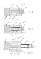
- Illustrated schematically in Figures 3-5 is a possible apparatus or mould that can be used for said purpose.
- the apparatus designated as a whole by 50, comprises three parts, and in particular a central part or insert 51 and two peripheral half-moulds 52, 53.
- Each half-mould 52, 53 has a respective impression 52a, 53a ( Figure 5 ), which is to define a respective portion of the external profile of the element 21.
- the remaining portion of the profile of the element 21 is instead defined in part by the insert 51 and in part directly by a terminal portion of the pipe 20.
- Formed in the half-mould 52 is a conduit 54, for injection of the moulding or overmoulding material.
- the insert 51 has a cylindrical part 51a having a distal end 51b with reduced cross section or diameter, configured to enable partial penetration in the end of the corrugated pipe 20, in order to provide a seal suitable for preventing the possibility of the overmoulding material penetrating inside the pipe itself during the process of injection.
- the maximum diameter of the end 51b can be slightly greater than the internal diameter of the pipe 20.
- the end of the pipe 20 is fitted on the region 51a of the insert 51, with the two half-moulds 52, 53 in the open position, i.e., divaricated (as shown in Figure 5 ).
- the material fills the aforesaid space 55 completely, thus forming the tubular element 21 directly on the pipe 20.
- a first inner surface of the portion 21a of the element 21, provided with reliefs and recesses, is determined by the external shape of the pipe 20, whilst a second inner surface of the portion 21b of the element 21, which is substantially smooth, is determined by the cylindrical part 51a of the insert 51. In this way, at least part of the inner surface of the element 21 assumes a shape that is complementary to the outer surface of the pipe 20.
- the half-moulds 52, 53 are opened, as may be seen in Figure 5 , and the pipe 20 with the element 21 coupled thereto can be slid off the insert 51.
- an apparatus conceptually similar to the one illustrated in Figures 3-5 can be used for the purposes of overmoulding the connection element 42 on the corrugated external pipe 30, or else for the purposes of moulding on the corrugated pipe 30 other elements (not shown), preferably made of elastomer.
- An apparatus conceptually similar to the one illustrated in Figures 3-5 can also be used for the purposes of just moulding a tubular element 21, designed to be mounted at a later date on the corrugated pipe 20, exploiting, for example, the elastic properties of the elastomeric material with which said element is preferably made.
- the apparatus 50 is equipped with an insert 51 having a shape different from the one exemplified, or else is equipped with a further insert, having at least in part the external shape of the corrugated pipe 20, or else having a completely smooth cylindrical surface (according to whether the aim is to provide a tubular element 21 with inner surface having reliefs and recesses or else completely smooth).
- the safety device according to the invention is less expensive to produce than the devices according to the known art, thanks to the replacement of the polyvinyl-chloride reinforced water-intake pipe with a pipe of simpler construction, which requires a reduced amount of material of lower cost and that has lower weight.
- both of the pipes of the device according to the invention may be formed with one and the same material, in particular polypropylene, simplifies disposal of the product at the end of its useful life.
- the elimination of the water-intake pipe made of polyvinyl chloride hence enables important benefits to be obtained also from the ecological standpoint.
- the use of an internal corrugated pipe prevents any risk of squeezing or local kinks typical of the known art, with evident advantages in terms of reliability and safety of the device.
- the tubular connection element when envisaged, simplifies the modalities of mechanical coupling and sealing of the corrugated pipe internal to the valve body of the device.
- the preferred field of application for the invention is that of anti-flooding safety devices equipped with electrical, or mechanical, or pneumatic shut-off means.
- the invention is in any case suitable for use also in relation to anti-flooding safety devices without valve means or that can be associated to independent shut-off means, i.e., of the type with simple visual warning or else of the type provided with only means for detection of an anomalous condition (such as water-leakage sensor means, or else flowmeter means, without necessarily providing a valve).
- the device according to the invention may be used to advantage in washing appliances, such as washing machines and dish-washers, but is in general applicable also to other types of electrical household appliances connected to a source of supply of liquid (such as, for example, refrigerators equipped with dispensers of beverages or cooled water).
- a source of supply of liquid such as, for example, refrigerators equipped with dispensers of beverages or cooled water.
- the elements 21 and 42 are made of a single body.
- the element 21 or 42 can possibly exert a sealing action on both of the pipes 20, 30.
- the formation of both of the corrugated pipes of the device 1 with one and the same material can enable a more convenient seal between them (for example, if they are both overmoulded with a single material, preferably an elastomer, which is glued or bonded to both of the corrugated pipes 20 and 30 and/or to at least part of the body 2 and/or of its coating 40).
- the elements 21 and 42 could also be configured as a piece moulded on itself, subsequently fitted on the pipe 20 and/or on the pipe 30.
- the aforesaid elements can be formed with material designed to shrink after being fitted on the pipe 20 and/or 30, for example following upon a thermal stress (heat-shrinking materials) or following upon cessation of a stress, for example a mechanical or thermal stress (materials with shape-memory effect).
- the safety-valve means that equip the device according to the invention can also be pneumatically or else mechanically actuated.
- an air conduit for example, a small flexible conduit
- a suitable transmission for example a Bowden cable with corresponding sheath
- the tubular element 21 could be overmoulded on the pipe 20, and the connection element 42 could be subsequently overmoulded both on a part of the element 21 and on a part of the external pipe 30.
- the device according to the invention can possibly comprise a plurality of corrugated pipes 20, 30 connected to one another in series, for example via intermediate-connection means.
- Said solution is envisaged in the case of modular safety devices or ones equipped with extensions, or else of the type in which the valve body is located in a position intermediate between two stretches of corrugated pipe 20, 30.
Landscapes
- Engineering & Computer Science (AREA)
- Textile Engineering (AREA)
- Rigid Pipes And Flexible Pipes (AREA)
- Quick-Acting Or Multi-Walled Pipe Joints (AREA)
- Cookers (AREA)
- Filters For Electric Vacuum Cleaners (AREA)
- Accessory Of Washing/Drying Machine, Commercial Washing/Drying Machine, Other Washing/Drying Machine (AREA)
- Centrifugal Separators (AREA)
- Lubricants (AREA)
Priority Applications (3)
| Application Number | Priority Date | Filing Date | Title |
|---|---|---|---|
| PL08165774T PL2014818T3 (pl) | 2005-12-15 | 2006-12-12 | Urządzenie zabezpieczające przed zalaniem do sprzętu gospodarstwa domowego, w szczególności do pralek |
| EP10181887.0A EP2314752B1 (de) | 2005-12-15 | 2006-12-12 | Überlaufschutzvorrichtung für Haushaltsgeräte, besonders für Waschgeräte |
| PL10181887T PL2314752T3 (pl) | 2005-12-15 | 2006-12-12 | Urządzenie zabezpieczające przed zalaniem do urządzenia gospodarstwa domowego |
Applications Claiming Priority (2)
| Application Number | Priority Date | Filing Date | Title |
|---|---|---|---|
| IT000876A ITTO20050876A1 (it) | 2005-12-15 | 2005-12-15 | Dispositivo di sicurezza antiallagamento per elettrodomestici, in particolare macchine di lavaggio |
| EP06125957A EP1798326B2 (de) | 2005-12-15 | 2006-12-12 | Sicherheitsvorrichtung gegen Überschwemmung für ein Haushaltsgerät |
Related Parent Applications (1)
| Application Number | Title | Priority Date | Filing Date |
|---|---|---|---|
| EP06125957A Division EP1798326B2 (de) | 2005-12-15 | 2006-12-12 | Sicherheitsvorrichtung gegen Überschwemmung für ein Haushaltsgerät |
Related Child Applications (1)
| Application Number | Title | Priority Date | Filing Date |
|---|---|---|---|
| EP10181887.0A Division-Into EP2314752B1 (de) | 2005-12-15 | 2006-12-12 | Überlaufschutzvorrichtung für Haushaltsgeräte, besonders für Waschgeräte |
Publications (3)
| Publication Number | Publication Date |
|---|---|
| EP2014818A2 true EP2014818A2 (de) | 2009-01-14 |
| EP2014818A3 EP2014818A3 (de) | 2009-02-18 |
| EP2014818B1 EP2014818B1 (de) | 2018-06-13 |
Family
ID=37823958
Family Applications (3)
| Application Number | Title | Priority Date | Filing Date |
|---|---|---|---|
| EP10181887.0A Active EP2314752B1 (de) | 2005-12-15 | 2006-12-12 | Überlaufschutzvorrichtung für Haushaltsgeräte, besonders für Waschgeräte |
| EP08165774.4A Active EP2014818B1 (de) | 2005-12-15 | 2006-12-12 | Überlaufschutzvorrichtung für haushaltsgeräte, besonders für waschgeräte |
| EP06125957A Active EP1798326B2 (de) | 2005-12-15 | 2006-12-12 | Sicherheitsvorrichtung gegen Überschwemmung für ein Haushaltsgerät |
Family Applications Before (1)
| Application Number | Title | Priority Date | Filing Date |
|---|---|---|---|
| EP10181887.0A Active EP2314752B1 (de) | 2005-12-15 | 2006-12-12 | Überlaufschutzvorrichtung für Haushaltsgeräte, besonders für Waschgeräte |
Family Applications After (1)
| Application Number | Title | Priority Date | Filing Date |
|---|---|---|---|
| EP06125957A Active EP1798326B2 (de) | 2005-12-15 | 2006-12-12 | Sicherheitsvorrichtung gegen Überschwemmung für ein Haushaltsgerät |
Country Status (6)
| Country | Link |
|---|---|
| EP (3) | EP2314752B1 (de) |
| AT (1) | ATE434678T1 (de) |
| DE (1) | DE602006007426D1 (de) |
| ES (3) | ES2328513T5 (de) |
| IT (1) | ITTO20050876A1 (de) |
| PL (3) | PL2014818T3 (de) |
Families Citing this family (26)
| Publication number | Priority date | Publication date | Assignee | Title |
|---|---|---|---|---|
| ITTO20070075A1 (it) * | 2007-02-02 | 2008-08-03 | Bitron Spa | Dispositivo acquastop perfezionato |
| IT1392966B1 (it) * | 2009-02-03 | 2012-04-02 | T&P S P A | Dispositivo antiallagamento di sicurezza per una macchina di lavaggio, e relativo metodo diassemblaggio |
| DE102010004272B4 (de) * | 2010-01-09 | 2011-09-22 | Norma Germany Gmbh | Kupplungselement |
| US9386904B2 (en) | 2010-11-18 | 2016-07-12 | Whirlpool Corporation | Dishwasher with movable liquid conduit |
| IT1406070B1 (it) * | 2011-02-18 | 2014-02-06 | Bitron Spa | Gruppo pre-montato per dispositivo acquastop e dispositivo che lo comprende |
| ITTO20110035U1 (it) | 2011-04-15 | 2012-10-16 | Eltek Spa | Dispositivo di sicurezza antiallagamento per elettrodomestici, in particolare macchine di lavaggio |
| ITTO20110337A1 (it) | 2011-04-15 | 2012-10-16 | Eltek Spa | Dispositivo di sicurezza contro perdite di fluido per elettrodomestici |
| ES2402016B1 (es) * | 2011-05-20 | 2014-03-10 | José PASCUAL MEDINA | Dispositivo para la detección de fugas de agua para electrodomésticos. |
| DE202012101676U1 (de) * | 2012-05-07 | 2012-05-21 | TI Automotive (Fuldabrück) GmbH | Schutzrohr für eine zu temperierende Medienleitung und Leitungsaggregat |
| DE102013211188A1 (de) * | 2013-06-14 | 2014-12-18 | BSH Bosch und Siemens Hausgeräte GmbH | Anschlussstück sowie Montagesatz |
| ITTO20130598A1 (it) | 2013-07-16 | 2015-01-17 | Bitron Spa | Dispositivo di carico e/o sicurezza antiallagamento per una macchina di lavaggio. |
| EP2947194B1 (de) | 2014-05-22 | 2018-09-05 | Schlemmer Gmbh | Kopplungsanordnung für ein haushaltsgerät, vorrichtung für ein haushaltsgerät sowie haushaltsgerät |
| DE102014210149A1 (de) | 2014-05-27 | 2015-12-03 | Schlemmer Gmbh | Schlaucheinrichtung zum Transportieren eines Fluids für ein Haushaltsgerät, Vorrichtung für ein Haushaltsgerät, Haushaltsgerät sowie Verfahren |
| KR20160031596A (ko) * | 2014-09-12 | 2016-03-23 | 동부대우전자 주식회사 | 감압 및 필터 기능을 갖는 세탁기 급수밸브용 통합장치 및 그 제조방법 |
| DE102016109967B4 (de) | 2016-05-31 | 2020-01-23 | BSH Hausgeräte GmbH | Schlauch für ein Haushaltsgerät, Schlaucheinrichtung, Vorrichtung, Haushaltsgerät sowie Verfahren zum Herstellen eines Schlauchs für ein Haushaltsgerät |
| DE102016110002B4 (de) | 2016-05-31 | 2022-10-13 | BSH Hausgeräte GmbH | Verfahren zum Herstellen eines Wellschlauchs für ein Haushaltsgerät, Wellschlauch, Vorrichtung sowie Haushaltsgerät |
| DE102017111056B4 (de) | 2017-05-22 | 2023-04-27 | Delfingen Fr-Anteuil S.A. | Verbundschlauch und Verfahren |
| EP3418436B1 (de) | 2017-06-21 | 2021-01-06 | Schlemmer Holding GmbH | Schlauchvorrichtung und anordnung |
| IT201700112681A1 (it) | 2017-10-06 | 2019-04-06 | Eltek Spa | Dispositivo di controllo idraulico per apparecchi e sistemi a conduzione di liquido |
| IT201700112704A1 (it) * | 2017-10-06 | 2019-04-06 | Eltek Spa | Dispositivo di controllo idraulico per apparecchi o sistemi domestici a conduzione di liquido |
| IT201900004055A1 (it) | 2019-03-20 | 2019-06-20 | Bitron Spa | Sistema di connessione non smontabile per collegare un tubo flessibile a un dispositivo idraulico |
| CN111779877B (zh) * | 2020-06-11 | 2022-03-01 | 武汉安达奇科技有限公司 | 一种基于永磁体磁力开合的电磁阀 |
| FR3114826A1 (fr) * | 2020-10-06 | 2022-04-08 | Stéphane COHEN | Système d’arret anti-debordement |
| IT202100012146A1 (it) * | 2021-05-12 | 2022-11-12 | Pavanello Srl | Gruppo valvola di sicurezza perfezionato, per il tubo di carico dell’acqua di lavatrici e lavastoviglie |
| EP4312702B1 (de) | 2021-05-12 | 2024-05-01 | Pavanello S.R.L. | Sicherheitsventilanordnung für wassereinlassschläuche von waschmaschinen und geschirrspülmaschinen |
| IT202300027939A1 (it) | 2023-12-22 | 2025-06-22 | Tp Reflex Group S P A | Dispositivo di sicurezza antiallagamento per un elettrodomestico, in particolare per una macchina di lavaggio, e relativo metodo di produzione |
Citations (3)
| Publication number | Priority date | Publication date | Assignee | Title |
|---|---|---|---|---|
| IT1207365B (it) | 1987-02-27 | 1989-05-17 | Eltek Spa | Dispositivo antiallagamento comprendente due valvole di sicurezza per macchine lavatrici |
| FR2742514A1 (fr) | 1995-12-13 | 1997-06-20 | Eltek Spa | Dispositif de securite anti-debordement et procede de fabrication d'un tel dispositif, notamment pour une machine a laver |
| DE10126104A1 (de) | 2000-05-29 | 2002-01-24 | Eltek Spa | Vorrichtung zum Einfüllen von Flüssigkeit in ein Haushaltsgerät, insbesondere eine Waschmaschine |
Family Cites Families (3)
| Publication number | Priority date | Publication date | Assignee | Title |
|---|---|---|---|---|
| GB1039515A (en) * | 1962-07-24 | 1966-08-17 | Power Aux Ies Ltd | Improvements in or relating to flexible pressure tubes and ducts |
| IT1208823B (it) * | 1985-07-31 | 1989-07-10 | Eltek Spa | Dispositivo a cartuccia reagente al l acqua in grado di attivare mezzi antiallagamento particolarmente per macchine lavatrici |
| JP3261969B2 (ja) * | 1996-02-29 | 2002-03-04 | 豊田合成株式会社 | ホースとその製造方法 |
-
2005
- 2005-12-15 IT IT000876A patent/ITTO20050876A1/it unknown
-
2006
- 2006-12-12 EP EP10181887.0A patent/EP2314752B1/de active Active
- 2006-12-12 ES ES06125957T patent/ES2328513T5/es active Active
- 2006-12-12 AT AT06125957T patent/ATE434678T1/de not_active IP Right Cessation
- 2006-12-12 EP EP08165774.4A patent/EP2014818B1/de active Active
- 2006-12-12 DE DE602006007426T patent/DE602006007426D1/de active Active
- 2006-12-12 PL PL08165774T patent/PL2014818T3/pl unknown
- 2006-12-12 ES ES10181887T patent/ES2420782T3/es active Active
- 2006-12-12 ES ES08165774.4T patent/ES2685769T3/es active Active
- 2006-12-12 PL PL06125957T patent/PL1798326T5/pl unknown
- 2006-12-12 EP EP06125957A patent/EP1798326B2/de active Active
- 2006-12-12 PL PL10181887T patent/PL2314752T3/pl unknown
Patent Citations (3)
| Publication number | Priority date | Publication date | Assignee | Title |
|---|---|---|---|---|
| IT1207365B (it) | 1987-02-27 | 1989-05-17 | Eltek Spa | Dispositivo antiallagamento comprendente due valvole di sicurezza per macchine lavatrici |
| FR2742514A1 (fr) | 1995-12-13 | 1997-06-20 | Eltek Spa | Dispositif de securite anti-debordement et procede de fabrication d'un tel dispositif, notamment pour une machine a laver |
| DE10126104A1 (de) | 2000-05-29 | 2002-01-24 | Eltek Spa | Vorrichtung zum Einfüllen von Flüssigkeit in ein Haushaltsgerät, insbesondere eine Waschmaschine |
Also Published As
| Publication number | Publication date |
|---|---|
| EP1798326A1 (de) | 2007-06-20 |
| ES2328513T3 (es) | 2009-11-13 |
| PL2314752T3 (pl) | 2013-09-30 |
| EP2314752B1 (de) | 2013-04-17 |
| EP1798326B2 (de) | 2012-01-11 |
| PL2014818T3 (pl) | 2019-03-29 |
| EP1798326B1 (de) | 2009-06-24 |
| EP2014818B1 (de) | 2018-06-13 |
| PL1798326T3 (pl) | 2009-12-31 |
| DE602006007426D1 (de) | 2009-08-06 |
| EP2014818A3 (de) | 2009-02-18 |
| ES2420782T3 (es) | 2013-08-26 |
| ATE434678T1 (de) | 2009-07-15 |
| ES2328513T5 (es) | 2012-05-16 |
| ITTO20050876A1 (it) | 2007-06-16 |
| PL1798326T5 (pl) | 2012-06-29 |
| ES2685769T3 (es) | 2018-10-11 |
| EP2314752A1 (de) | 2011-04-27 |
Similar Documents
| Publication | Publication Date | Title |
|---|---|---|
| EP2014818B1 (de) | Überlaufschutzvorrichtung für haushaltsgeräte, besonders für waschgeräte | |
| EP0748972B1 (de) | Flexibler Schlauch mit einer Seele aus Verbundwerkstoff | |
| MX2011002710A (es) | Metodo y aparato para retencion de la punta de un caño de grifo. | |
| US4927061A (en) | Dispensing valve with elastic sealing tube | |
| EP2696740B1 (de) | Sicherheitsvorrichtung gegen überschwemmungen für haushaltsgeräte, insbesondere waschmaschinen | |
| US20110036436A1 (en) | Water conducting household appliance | |
| ITTO951004A1 (it) | Dispositivo di sicurezza antiallagamento per macchine di lavaggio. | |
| US20080169034A1 (en) | System and method for controlling the water flow of household appliances | |
| US5687951A (en) | Drain valve | |
| EP1085119B1 (de) | Hydraulische Vorrichtung mit einem Sensor für Haushaltsgeräte, insbesondere für Waschmaschinen, und Herstellungsverfahren einer solchen Vorrichtung | |
| US20030051763A1 (en) | Plastic corrugation corrugated pipe with monolithic container | |
| EP1432940A1 (de) | Kupplung | |
| US5487406A (en) | Drain control valve and manifold system | |
| EP3379125B1 (de) | Druckfestes schlauch und anschlussanordnung und entsprechendes herstelluingsverfahren | |
| RU189968U1 (ru) | Гибкий трубопровод | |
| EP1955640B1 (de) | Verbesserte Wasserstoppvorrichtung | |
| EP4574004A1 (de) | Sicherheitsvorrichtung gegen überschwemmung für ein haushaltsgerät, insbesondere für eine waschmaschine, und verfahren zu ihrer herstellung | |
| US20150369401A1 (en) | Leak-resistant solar panel connector | |
| EP0819918A2 (de) | Vorrichtung zum Regeln einer Flüssigkeit | |
| CN220069491U (zh) | 一种管线机的排水组件 | |
| CN219943444U (zh) | 一种适配机器人的注胶机胶嘴 | |
| KR20190111273A (ko) | 배관 세정 장치 | |
| WO2020065510A1 (en) | Diverter device for managing flows of liquid, in particular in household appliances, such as washing machines, dishwashers or the like | |
| KR100923788B1 (ko) | 유체손실방지용 어셈블리 | |
| RU42086U1 (ru) | Изделие водосливной санитарно-технической арматуры |
Legal Events
| Date | Code | Title | Description |
|---|---|---|---|
| PUAI | Public reference made under article 153(3) epc to a published international application that has entered the european phase |
Free format text: ORIGINAL CODE: 0009012 |
|
| AC | Divisional application: reference to earlier application |
Ref document number: 1798326 Country of ref document: EP Kind code of ref document: P |
|
| AK | Designated contracting states |
Kind code of ref document: A2 Designated state(s): AT BE BG CH CY CZ DE DK EE ES FI FR GB GR HU IE IS IT LI LT LU LV MC NL PL PT RO SE SI SK TR |
|
| PUAL | Search report despatched |
Free format text: ORIGINAL CODE: 0009013 |
|
| AK | Designated contracting states |
Kind code of ref document: A3 Designated state(s): AT BE BG CH CY CZ DE DK EE ES FI FR GB GR HU IE IS IT LI LT LU LV MC NL PL PT RO SE SI SK TR |
|
| 17P | Request for examination filed |
Effective date: 20090414 |
|
| AKX | Designation fees paid |
Designated state(s): AT BE BG CH CY CZ DE DK EE ES FI FR GB GR HU IE IS IT LI LT LU LV MC NL PL PT RO SE SI SK TR |
|
| 17Q | First examination report despatched |
Effective date: 20160610 |
|
| REG | Reference to a national code |
Ref country code: DE Ref legal event code: R079 Ref document number: 602006055640 Country of ref document: DE Free format text: PREVIOUS MAIN CLASS: D06F0039080000 Ipc: A47L0015420000 |
|
| GRAP | Despatch of communication of intention to grant a patent |
Free format text: ORIGINAL CODE: EPIDOSNIGR1 |
|
| RIC1 | Information provided on ipc code assigned before grant |
Ipc: D06F 39/08 20060101ALI20171026BHEP Ipc: A47L 15/42 20060101AFI20171026BHEP |
|
| INTG | Intention to grant announced |
Effective date: 20171128 |
|
| GRAJ | Information related to disapproval of communication of intention to grant by the applicant or resumption of examination proceedings by the epo deleted |
Free format text: ORIGINAL CODE: EPIDOSDIGR1 |
|
| GRAS | Grant fee paid |
Free format text: ORIGINAL CODE: EPIDOSNIGR3 |
|
| INTC | Intention to grant announced (deleted) | ||
| GRAP | Despatch of communication of intention to grant a patent |
Free format text: ORIGINAL CODE: EPIDOSNIGR1 |
|
| GRAA | (expected) grant |
Free format text: ORIGINAL CODE: 0009210 |
|
| INTG | Intention to grant announced |
Effective date: 20180416 |
|
| AC | Divisional application: reference to earlier application |
Ref document number: 1798326 Country of ref document: EP Kind code of ref document: P |
|
| AK | Designated contracting states |
Kind code of ref document: B1 Designated state(s): AT BE BG CH CY CZ DE DK EE ES FI FR GB GR HU IE IS IT LI LT LU LV MC NL PL PT RO SE SI SK TR |
|
| REG | Reference to a national code |
Ref country code: GB Ref legal event code: FG4D |
|
| REG | Reference to a national code |
Ref country code: CH Ref legal event code: EP Ref country code: AT Ref legal event code: REF Ref document number: 1007612 Country of ref document: AT Kind code of ref document: T Effective date: 20180615 |
|
| REG | Reference to a national code |
Ref country code: IE Ref legal event code: FG4D |
|
| REG | Reference to a national code |
Ref country code: DE Ref legal event code: R096 Ref document number: 602006055640 Country of ref document: DE |
|
| REG | Reference to a national code |
Ref country code: SE Ref legal event code: TRGR |
|
| REG | Reference to a national code |
Ref country code: ES Ref legal event code: FG2A Ref document number: 2685769 Country of ref document: ES Kind code of ref document: T3 Effective date: 20181011 |
|
| REG | Reference to a national code |
Ref country code: NL Ref legal event code: MP Effective date: 20180613 |
|
| REG | Reference to a national code |
Ref country code: LT Ref legal event code: MG4D |
|
| PG25 | Lapsed in a contracting state [announced via postgrant information from national office to epo] |
Ref country code: FI Free format text: LAPSE BECAUSE OF FAILURE TO SUBMIT A TRANSLATION OF THE DESCRIPTION OR TO PAY THE FEE WITHIN THE PRESCRIBED TIME-LIMIT Effective date: 20180613 Ref country code: LT Free format text: LAPSE BECAUSE OF FAILURE TO SUBMIT A TRANSLATION OF THE DESCRIPTION OR TO PAY THE FEE WITHIN THE PRESCRIBED TIME-LIMIT Effective date: 20180613 Ref country code: BG Free format text: LAPSE BECAUSE OF FAILURE TO SUBMIT A TRANSLATION OF THE DESCRIPTION OR TO PAY THE FEE WITHIN THE PRESCRIBED TIME-LIMIT Effective date: 20180913 Ref country code: CY Free format text: LAPSE BECAUSE OF FAILURE TO SUBMIT A TRANSLATION OF THE DESCRIPTION OR TO PAY THE FEE WITHIN THE PRESCRIBED TIME-LIMIT Effective date: 20180613 |
|
| PG25 | Lapsed in a contracting state [announced via postgrant information from national office to epo] |
Ref country code: LV Free format text: LAPSE BECAUSE OF FAILURE TO SUBMIT A TRANSLATION OF THE DESCRIPTION OR TO PAY THE FEE WITHIN THE PRESCRIBED TIME-LIMIT Effective date: 20180613 Ref country code: GR Free format text: LAPSE BECAUSE OF FAILURE TO SUBMIT A TRANSLATION OF THE DESCRIPTION OR TO PAY THE FEE WITHIN THE PRESCRIBED TIME-LIMIT Effective date: 20180914 |
|
| REG | Reference to a national code |
Ref country code: AT Ref legal event code: MK05 Ref document number: 1007612 Country of ref document: AT Kind code of ref document: T Effective date: 20180613 |
|
| PG25 | Lapsed in a contracting state [announced via postgrant information from national office to epo] |
Ref country code: NL Free format text: LAPSE BECAUSE OF FAILURE TO SUBMIT A TRANSLATION OF THE DESCRIPTION OR TO PAY THE FEE WITHIN THE PRESCRIBED TIME-LIMIT Effective date: 20180613 |
|
| PG25 | Lapsed in a contracting state [announced via postgrant information from national office to epo] |
Ref country code: AT Free format text: LAPSE BECAUSE OF FAILURE TO SUBMIT A TRANSLATION OF THE DESCRIPTION OR TO PAY THE FEE WITHIN THE PRESCRIBED TIME-LIMIT Effective date: 20180613 Ref country code: RO Free format text: LAPSE BECAUSE OF FAILURE TO SUBMIT A TRANSLATION OF THE DESCRIPTION OR TO PAY THE FEE WITHIN THE PRESCRIBED TIME-LIMIT Effective date: 20180613 Ref country code: CZ Free format text: LAPSE BECAUSE OF FAILURE TO SUBMIT A TRANSLATION OF THE DESCRIPTION OR TO PAY THE FEE WITHIN THE PRESCRIBED TIME-LIMIT Effective date: 20180613 Ref country code: SK Free format text: LAPSE BECAUSE OF FAILURE TO SUBMIT A TRANSLATION OF THE DESCRIPTION OR TO PAY THE FEE WITHIN THE PRESCRIBED TIME-LIMIT Effective date: 20180613 Ref country code: EE Free format text: LAPSE BECAUSE OF FAILURE TO SUBMIT A TRANSLATION OF THE DESCRIPTION OR TO PAY THE FEE WITHIN THE PRESCRIBED TIME-LIMIT Effective date: 20180613 Ref country code: IS Free format text: LAPSE BECAUSE OF FAILURE TO SUBMIT A TRANSLATION OF THE DESCRIPTION OR TO PAY THE FEE WITHIN THE PRESCRIBED TIME-LIMIT Effective date: 20181013 |
|
| REG | Reference to a national code |
Ref country code: DE Ref legal event code: R097 Ref document number: 602006055640 Country of ref document: DE |
|
| PLBE | No opposition filed within time limit |
Free format text: ORIGINAL CODE: 0009261 |
|
| STAA | Information on the status of an ep patent application or granted ep patent |
Free format text: STATUS: NO OPPOSITION FILED WITHIN TIME LIMIT |
|
| 26N | No opposition filed |
Effective date: 20190314 |
|
| PG25 | Lapsed in a contracting state [announced via postgrant information from national office to epo] |
Ref country code: SI Free format text: LAPSE BECAUSE OF FAILURE TO SUBMIT A TRANSLATION OF THE DESCRIPTION OR TO PAY THE FEE WITHIN THE PRESCRIBED TIME-LIMIT Effective date: 20180613 Ref country code: DK Free format text: LAPSE BECAUSE OF FAILURE TO SUBMIT A TRANSLATION OF THE DESCRIPTION OR TO PAY THE FEE WITHIN THE PRESCRIBED TIME-LIMIT Effective date: 20180613 |
|
| REG | Reference to a national code |
Ref country code: CH Ref legal event code: PL |
|
| PG25 | Lapsed in a contracting state [announced via postgrant information from national office to epo] |
Ref country code: LU Free format text: LAPSE BECAUSE OF NON-PAYMENT OF DUE FEES Effective date: 20181212 Ref country code: MC Free format text: LAPSE BECAUSE OF FAILURE TO SUBMIT A TRANSLATION OF THE DESCRIPTION OR TO PAY THE FEE WITHIN THE PRESCRIBED TIME-LIMIT Effective date: 20180613 |
|
| REG | Reference to a national code |
Ref country code: IE Ref legal event code: MM4A |
|
| REG | Reference to a national code |
Ref country code: BE Ref legal event code: MM Effective date: 20181231 |
|
| PG25 | Lapsed in a contracting state [announced via postgrant information from national office to epo] |
Ref country code: IE Free format text: LAPSE BECAUSE OF NON-PAYMENT OF DUE FEES Effective date: 20181212 |
|
| PG25 | Lapsed in a contracting state [announced via postgrant information from national office to epo] |
Ref country code: BE Free format text: LAPSE BECAUSE OF NON-PAYMENT OF DUE FEES Effective date: 20181231 |
|
| PG25 | Lapsed in a contracting state [announced via postgrant information from national office to epo] |
Ref country code: LI Free format text: LAPSE BECAUSE OF NON-PAYMENT OF DUE FEES Effective date: 20181231 Ref country code: CH Free format text: LAPSE BECAUSE OF NON-PAYMENT OF DUE FEES Effective date: 20181231 |
|
| PG25 | Lapsed in a contracting state [announced via postgrant information from national office to epo] |
Ref country code: PT Free format text: LAPSE BECAUSE OF FAILURE TO SUBMIT A TRANSLATION OF THE DESCRIPTION OR TO PAY THE FEE WITHIN THE PRESCRIBED TIME-LIMIT Effective date: 20180613 |
|
| PG25 | Lapsed in a contracting state [announced via postgrant information from national office to epo] |
Ref country code: HU Free format text: LAPSE BECAUSE OF FAILURE TO SUBMIT A TRANSLATION OF THE DESCRIPTION OR TO PAY THE FEE WITHIN THE PRESCRIBED TIME-LIMIT; INVALID AB INITIO Effective date: 20061212 |
|
| PGFP | Annual fee paid to national office [announced via postgrant information from national office to epo] |
Ref country code: TR Payment date: 20221122 Year of fee payment: 17 Ref country code: SE Payment date: 20221223 Year of fee payment: 17 Ref country code: GB Payment date: 20221220 Year of fee payment: 17 Ref country code: FR Payment date: 20221222 Year of fee payment: 17 |
|
| PGFP | Annual fee paid to national office [announced via postgrant information from national office to epo] |
Ref country code: PL Payment date: 20221115 Year of fee payment: 17 |
|
| PGFP | Annual fee paid to national office [announced via postgrant information from national office to epo] |
Ref country code: ES Payment date: 20230120 Year of fee payment: 17 |
|
| PGFP | Annual fee paid to national office [announced via postgrant information from national office to epo] |
Ref country code: IT Payment date: 20221213 Year of fee payment: 17 Ref country code: DE Payment date: 20221227 Year of fee payment: 17 |
|
| P01 | Opt-out of the competence of the unified patent court (upc) registered |
Effective date: 20230529 |
|
| REG | Reference to a national code |
Ref country code: DE Ref legal event code: R119 Ref document number: 602006055640 Country of ref document: DE |
|
| REG | Reference to a national code |
Ref country code: SE Ref legal event code: EUG |
|
| GBPC | Gb: european patent ceased through non-payment of renewal fee |
Effective date: 20231212 |
|
| PG25 | Lapsed in a contracting state [announced via postgrant information from national office to epo] |
Ref country code: DE Free format text: LAPSE BECAUSE OF NON-PAYMENT OF DUE FEES Effective date: 20240702 |
|
| PG25 | Lapsed in a contracting state [announced via postgrant information from national office to epo] |
Ref country code: GB Free format text: LAPSE BECAUSE OF NON-PAYMENT OF DUE FEES Effective date: 20231212 |
|
| PG25 | Lapsed in a contracting state [announced via postgrant information from national office to epo] |
Ref country code: FR Free format text: LAPSE BECAUSE OF NON-PAYMENT OF DUE FEES Effective date: 20231231 |
|
| PG25 | Lapsed in a contracting state [announced via postgrant information from national office to epo] |
Ref country code: GB Free format text: LAPSE BECAUSE OF NON-PAYMENT OF DUE FEES Effective date: 20231212 Ref country code: FR Free format text: LAPSE BECAUSE OF NON-PAYMENT OF DUE FEES Effective date: 20231231 Ref country code: DE Free format text: LAPSE BECAUSE OF NON-PAYMENT OF DUE FEES Effective date: 20240702 |
|
| REG | Reference to a national code |
Ref country code: ES Ref legal event code: FD2A Effective date: 20250128 |
|
| PG25 | Lapsed in a contracting state [announced via postgrant information from national office to epo] |
Ref country code: ES Free format text: LAPSE BECAUSE OF NON-PAYMENT OF DUE FEES Effective date: 20231213 |
|
| PG25 | Lapsed in a contracting state [announced via postgrant information from national office to epo] |
Ref country code: PL Free format text: LAPSE BECAUSE OF NON-PAYMENT OF DUE FEES Effective date: 20231212 |
|
| PG25 | Lapsed in a contracting state [announced via postgrant information from national office to epo] |
Ref country code: IT Free format text: LAPSE BECAUSE OF NON-PAYMENT OF DUE FEES Effective date: 20231212 |
|
| PG25 | Lapsed in a contracting state [announced via postgrant information from national office to epo] |
Ref country code: SE Free format text: LAPSE BECAUSE OF NON-PAYMENT OF DUE FEES Effective date: 20231213 |