EP2014777A1 - Method and device for thermal treatment of metal sheet - Google Patents
Method and device for thermal treatment of metal sheet Download PDFInfo
- Publication number
- EP2014777A1 EP2014777A1 EP07112278A EP07112278A EP2014777A1 EP 2014777 A1 EP2014777 A1 EP 2014777A1 EP 07112278 A EP07112278 A EP 07112278A EP 07112278 A EP07112278 A EP 07112278A EP 2014777 A1 EP2014777 A1 EP 2014777A1
- Authority
- EP
- European Patent Office
- Prior art keywords
- metal body
- contact
- contact plate
- temperature
- metal
- Prior art date
- Legal status (The legal status is an assumption and is not a legal conclusion. Google has not performed a legal analysis and makes no representation as to the accuracy of the status listed.)
- Granted
Links
- 239000002184 metal Substances 0.000 title claims abstract description 159
- 229910052751 metal Inorganic materials 0.000 title claims abstract description 159
- 238000000034 method Methods 0.000 title claims abstract description 68
- 238000007669 thermal treatment Methods 0.000 title claims abstract description 25
- HCHKCACWOHOZIP-UHFFFAOYSA-N Zinc Chemical compound [Zn] HCHKCACWOHOZIP-UHFFFAOYSA-N 0.000 claims abstract description 7
- 230000007704 transition Effects 0.000 claims abstract description 7
- 229910052725 zinc Inorganic materials 0.000 claims abstract description 7
- 239000011701 zinc Substances 0.000 claims abstract description 7
- 238000001816 cooling Methods 0.000 abstract description 19
- 238000010438 heat treatment Methods 0.000 abstract description 19
- 238000003825 pressing Methods 0.000 abstract 2
- 230000001105 regulatory effect Effects 0.000 abstract 2
- 239000000463 material Substances 0.000 description 13
- 230000003247 decreasing effect Effects 0.000 description 4
- 230000006378 damage Effects 0.000 description 3
- 238000007711 solidification Methods 0.000 description 3
- 230000008023 solidification Effects 0.000 description 3
- 238000011282 treatment Methods 0.000 description 3
- 230000015572 biosynthetic process Effects 0.000 description 2
- 239000002826 coolant Substances 0.000 description 2
- 238000009413 insulation Methods 0.000 description 2
- 239000007788 liquid Substances 0.000 description 2
- 239000007769 metal material Substances 0.000 description 2
- 229910000831 Steel Inorganic materials 0.000 description 1
- 230000006978 adaptation Effects 0.000 description 1
- 239000003795 chemical substances by application Substances 0.000 description 1
- 238000004891 communication Methods 0.000 description 1
- 230000001934 delay Effects 0.000 description 1
- 238000006073 displacement reaction Methods 0.000 description 1
- 238000001704 evaporation Methods 0.000 description 1
- 230000008020 evaporation Effects 0.000 description 1
- 230000001939 inductive effect Effects 0.000 description 1
- 239000011810 insulating material Substances 0.000 description 1
- 238000005259 measurement Methods 0.000 description 1
- 239000010959 steel Substances 0.000 description 1
- 238000005496 tempering Methods 0.000 description 1
- 230000002123 temporal effect Effects 0.000 description 1
Images


Classifications
-
- C—CHEMISTRY; METALLURGY
- C21—METALLURGY OF IRON
- C21D—MODIFYING THE PHYSICAL STRUCTURE OF FERROUS METALS; GENERAL DEVICES FOR HEAT TREATMENT OF FERROUS OR NON-FERROUS METALS OR ALLOYS; MAKING METAL MALLEABLE, e.g. BY DECARBURISATION OR TEMPERING
- C21D1/00—General methods or devices for heat treatment, e.g. annealing, hardening, quenching or tempering
- C21D1/34—Methods of heating
-
- C—CHEMISTRY; METALLURGY
- C21—METALLURGY OF IRON
- C21D—MODIFYING THE PHYSICAL STRUCTURE OF FERROUS METALS; GENERAL DEVICES FOR HEAT TREATMENT OF FERROUS OR NON-FERROUS METALS OR ALLOYS; MAKING METAL MALLEABLE, e.g. BY DECARBURISATION OR TEMPERING
- C21D1/00—General methods or devices for heat treatment, e.g. annealing, hardening, quenching or tempering
- C21D1/62—Quenching devices
- C21D1/673—Quenching devices for die quenching
-
- C—CHEMISTRY; METALLURGY
- C21—METALLURGY OF IRON
- C21D—MODIFYING THE PHYSICAL STRUCTURE OF FERROUS METALS; GENERAL DEVICES FOR HEAT TREATMENT OF FERROUS OR NON-FERROUS METALS OR ALLOYS; MAKING METAL MALLEABLE, e.g. BY DECARBURISATION OR TEMPERING
- C21D9/00—Heat treatment, e.g. annealing, hardening, quenching or tempering, adapted for particular articles; Furnaces therefor
- C21D9/46—Heat treatment, e.g. annealing, hardening, quenching or tempering, adapted for particular articles; Furnaces therefor for sheet metals
-
- C—CHEMISTRY; METALLURGY
- C21—METALLURGY OF IRON
- C21D—MODIFYING THE PHYSICAL STRUCTURE OF FERROUS METALS; GENERAL DEVICES FOR HEAT TREATMENT OF FERROUS OR NON-FERROUS METALS OR ALLOYS; MAKING METAL MALLEABLE, e.g. BY DECARBURISATION OR TEMPERING
- C21D11/00—Process control or regulation for heat treatments
-
- C—CHEMISTRY; METALLURGY
- C21—METALLURGY OF IRON
- C21D—MODIFYING THE PHYSICAL STRUCTURE OF FERROUS METALS; GENERAL DEVICES FOR HEAT TREATMENT OF FERROUS OR NON-FERROUS METALS OR ALLOYS; MAKING METAL MALLEABLE, e.g. BY DECARBURISATION OR TEMPERING
- C21D2221/00—Treating localised areas of an article
Definitions
- the invention relates to a method for the thermal treatment of at least one metal body. Furthermore, the invention relates to an apparatus for carrying out such a method.
- the inductive heating and the heating by laser are known. Both methods allow a local thermal treatment on a defined partial surface of a metal body. Due to the rapid local heating of the material disadvantages such as a distortion of the metal body and thus deviations after heating arise, a difficult Control and control of the temperature in the heating field due to uneven distance between the heat source and the plate due to distortion, uneven temperature distribution on the heating zone causing inhomogeneous material properties, and partial or complete destruction of the zinc layer by evaporation in metal bodies with a zinc layer.
- the invention has for its object to provide a comparison with the prior art improved, in particular a low distortion and / or improved in terms of temperature control process for the thermal treatment of metal bodies. Furthermore, a device for carrying out the method is to be offered.
- the at least one metal body is fixed in its position.
- a first contact plate is brought into contact with at least a first surface section of the metal body and a second contact plate is brought into contact with at least one second surface section of the metal body.
- the contact plates are surface substantially or completely formed according to the contour of the surface portions of the metal body and in the state of contact with the metal body substantially parallel to each other arranged.
- at least one contact plate during the contacting of the metal body has a relation to the metal body higher or lower temperature.
- the temperature of the metal body compensates during contacting the temperature of the contact plate. This leads to a thermal treatment of the metal body. It is thus possible both heating and cooling of the metal body by contact plates. In addition, the temperature-induced distortion is minimized by the uniform temperature change and the surface pressure through the contact plates.
- the method according to the invention can be used variably.
- the temperature which the contact plate has or on which the metal body is brought, as well as the period of time for which the contact between contact plates and metal body can be chosen almost arbitrarily. It is thus possible to variably adapt the method according to the invention to the desired parameters of the thermal treatment and to the material to be treated. In particular, both thermal treatments are possible, which lead to a softening of the material as well as thermal treatments that lead to a solidification.
- the contact between metal body and contact plates may be formed such that the contact plates and the metal body touch directly. However, it may also be an intermediate layer, such as a contact agent, which improves the temperature balance between the contact plate and metal body, be present.
- the surface portions communicating with the contact plates may extend over or cover completely large portions of the metal body as well as forming only small, localized areas of the metal body. If only locally limited areas are connected to the contact plates, a local thermal treatment of the metal body can be carried out.
- the metal body is formed as a sheet metal or sheet metal part and the at least one first surface portion is located on the upper side of the sheet metal and the at least one second surface portion is located on the underside of the sheet metal.
- a metal body is at least partially with a zinc layer provided sheet metal or sheet metal parts used.
- a zinc layer provided sheet metal or sheet metal parts used.
- high-strength, galvanized sheets and sheet metal parts can be used from the body shop.
- the contact between metal body and contact plate prevents the damage or destruction of the zinc layer.
- a metal body is used, which is formed in a later step, and the at least one first and second surface portion are in or near the area to be reformed later.
- the contact plates are pressed onto the metal body. This has the advantage that a contact between contact plates and metal body is ensured particularly secure. In addition, thereby minimizing the delays is particularly effective possible.
- the temperature of the at least one contact plate with elevated or lowered temperature before and / or during the contacting of the metal body with the contact plates is controlled by a temperature control device.
- a temperature control device it is possible the temperature of the contact plate and thus also the temperature of the metal body during the entire thermal treatment control or regulate.
- such a control device both preheat prior to contacting the contact plates, heat the contact plates during contacting, keep a desired temperature during contacting constant or provide for a controlled lowering of the temperature in the course of contacting.
- the control device can also provide for a defined cooling of the contact plates.
- a contact plate is removed. If all the contact plates removed, this leads to a free alignment of the temperature of the metal body to the ambient temperature. If a contact plate is removed, this leads to a partial free alignment of the temperature of the metal body. In areas of the metal body, which are still associated with a contact plate, the temperature of the metal body, however, is influenced by the contact plate. This makes it possible to influence the formation of the temperature profile of the metal body by removing one or more contact plates.
- first contact plates and / or the second contact plates are interconnected with a flexible transition element. This allows the individual contact plates to adapt flexibly to different geometries of the basic body.
- the metal body is heated in a first method step and brought into contact with at least one contact plate in a subsequent method step.
- the contact plate has a relation to the metal body lower temperature. Due to the lower temperature of the contact plates, the metal body is cooled after heating. This cooling is well controlled due to the contact plates in terms of temperature control.
- the heating of the metal body can be done by contact with contact plates, which have a higher temperature than the metal body.
- the metal body can also be heated without contact with contact plates, for example with an inductor.
- the same contact plates in the subsequent process step can also be brought to a temperature lower than that of the metal body and thus serve for cooling. But it can also be used for heating other contact plates than for cooling.
- the metal body is brought into contact with at least one contact plates in a first method step.
- the contact plate has a relation to the metal body higher temperature. Due to the higher temperature of the contact plates, the metal body is heated. This heating due to the contact plates in terms of temperature control is well controlled. In addition, will minimized due to the contacting of the warp caused by warpage.
- the at least one contact plate which has an elevated temperature relative to the metal body, is preferably heated to this temperature by an energy source. This can be done, for example, inductively or conductively.
- the heating can take place either before the contact with the metal body or during the contacting.
- the contact plates can also be brought into mutual contact with one another before the contact with the metal body. It can then be heated a contact plate. The heat then transfers to the others with these contact plates in contact. Subsequently, the contact plates can be separated from each other and brought into contact with the metal body.
- the contact plates can both be made of the same material as well as of different materials.
- contact plates that are heated made of a metallic material, such as steel.
- Contact plates that are not heated may preferably be made of both metallic and non-metallic materials.
- contact plates, the not heated made of an insulating material. This has the advantage that the heat loss is reduced.
- the contact plates may have an insulating layer. Also, the heat loss can be reduced thereby.
- At least one contact plate is cooled.
- the temperature of the metal body can be precisely controlled.
- the cooling rate of the metal body can thereby be set precisely. For example, solidification of the material in the area of the cooled contact plates is possible.
- the cooled contact plates may also have cooling channels. This allows the passage of liquid or gaseous coolants through the contact plates, which leads to a particularly accurate cooling.
- the device according to the invention is designed such that it is suitable for carrying out the method according to the invention according to one of the claims relating to the method.
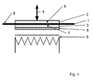
- Fig. 1 shows a schematic sectional view of an embodiment of the method according to the invention.
- the metal body 1 has been brought by the displacement of the first contact plate 2 in the direction 4 with this in contact.
- a first surface portion 6 of the metal body 1 communicates with the first contact plate 2.
- the metal body 1 has been brought into contact with the second contact plate 3.
- a second surface portion 7 is in communication with the second contact plate 3.
- the contact plates 2, 3 are formed flat in accordance with the contour of the surface sections 6, 7 of the metal body 1 and are arranged running parallel to one another in the state of contacting with the metal body 1.
- either only one contact plate or a plurality of contact plates can be displaceable.
- the contact can be designed such that the first contact plate 2 and the second contact plate 3 simultaneously with the Metal body 1 are brought into contact. However, it is also possible first to bring a contact plate 2 into contact with the metal body 1 and to add a second contact plate 3 only later in time.
- the second contact plate 3 is or was brought by an energy source 5 to a relative to the metal body 1 increased or decreased temperature.
- Energy source 5 is understood below to mean any device that can be used for cooling or heating objects.
- the contact plates 2, 3 are arranged running parallel to one another.
- the second contact plate 3 has an insulation layer 8. By this insulating layer 8, the heat or cooling loss can be reduced.
- the temperature of the metal body 1 can be kept constant. However, it is also possible to vary the temperature of the metal body in the course of contacting by the defined change in the temperatures of the contact plates. Thus, a very variable adaptation of the temperature-time curve is possible.
- the temperature profile along a contact plate 2, 3 can be designed such that an almost constant temperature is established over the entire contact plate 2, 3.
- the contact plate 2, 3 can also be heated or cooled in such a way that regions with different temperatures form within the contact plate 2, 3.
- the first surface portion 6 brought into contact with the contact plates 2, 3 and the second surface portion 7 of the metal body 1 may be the same size. However, they can also have different sizes (not shown).
- a sensor element 9 may be attached on the metal body 1.
- the sensor element 9 is a temperature sensor element. This allows the measurement of the temperature of the metal body.
- the temperature measured in this way can serve, for example, as an input variable for a temperature control device that controls or regulates the temperature-time profile of the thermal treatment.
- the method can also be configured such that a plurality of metal bodies are simultaneously brought into contact with at least one first and / or one at least one second contact plate simultaneously.
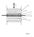
- Fig. 2 shows a schematic sectional view of another embodiment of the method according to the invention.
- the metal body 1 was brought into contact by moving the first contact plate 2 with this and a second contact plate 3.
- the contact plates are arranged to run parallel to each other.
- the first contact plate 2 is or was replaced by a Power source 5 is brought to a relative to the metal body increased or decreased temperature.
- the second contact plate 3 is or was brought by a further energy source 5 to a relative to the metal body increased or decreased temperature.
- the first contact plate 2 and the second contact plate 3 can be brought by the energy sources both at the same temperature and at different temperatures.
- Fig. 3a shows a schematic sectional view of a first process step to a temperature of the contact plates.
- the first contact plate 2 and the second contact plate 3 are brought into mutual contact with each other before contacting with the metal body. Subsequently, the second contact plate 3 is heated or cooled by the power source 5. The temperature is subsequently transferred to the first contact plate 2 which is in contact with the second contact plate 3.
- Fig. 3b shows a schematic sectional view of a second method step to an application of the contact plates, which conform to the in Fig. 3a followed by the process step.
- the first contact plate 2 and the second contact plate 3 are separated from each other.
- the metal body 1 is inserted between the separate contact plates.
- Fig. 3c shows a schematic sectional view of a third process step to an application of the contact plates, which conform to the in Fig. 3b followed by the process step.
- the first contact plate 2 and the second contact plate 3 were brought into contact with the metal body 1. It owns both the first Contact plate 2 and the second contact plate 2 a relative to the metal body 1 increased or decreased temperature.
- Fig. 4 shows a schematic sectional view of another embodiment of the method according to the invention.
- the metal body 1 was brought into contact with a first contact plate 2 and a second contact plate 3.
- the first contact plate 2 is in contact with a plurality of first surface portions 6 of the metal body 1.
- the second contact plate 3 is in contact with a plurality of second surface portions 7 of the metal body 1.
- the contact plates are formed flat according to the contour of the surface portions of the metal body and in the state of contacting with the metal body substantially parallel to each other, ie they extend at a constant distance from each other, arranged.
- the first contact plate 2 and third contact plate 3 may be formed so that they can be cooled. As a result, the metal body can be cooled exactly in the course of the thermal treatment.
- cooling can be carried out so that, for example, a solidification of the material occurs.
- cooling channels may be present in the first contact plate 2 and / or in the second contact plate 3. Through these cooling channels liquid or gaseous coolant can be introduced.
- the same contact plates 2, 3 can be used for both partial treatments.
- the cooling can also be done by contact elements that differ from the contact plate 2.3 for heating.
- Fig. 5 shows a schematic sectional view of a further process step of the method according to the invention, in which, after the desired temperature for the thermal treatment has been applied to the metal body, at least one contact plate has been removed.
- the metal body 1 is only in contact with a first contact plate 2. This makes it possible to influence the formation of the temperature profile of the metal body 1.
- Fig. 6 shows a schematic sectional view of another embodiment of the method according to the invention.
- first contact plates 2 and a plurality of second contact plates 3 were brought into contact with a metal body 1.
- a contact plate pair of a first contact plate 2 and a second contact plate 3 are arranged parallel to each other.
- the individual contact plate pairs are interconnected by flexible transition elements 10.
- flexible transition elements 10 As a result, a particularly flexible contacting of the contact plates 2, 3 with the metal body 1 is achieved. Due to the flexible transition elements 10, it is possible to easily adapt the contact plates 2, 3 to differently shaped metal bodies 1.
- Fig. 7 shows a schematic sectional view of another embodiment of the method according to the invention.
- first contact plates 2 and a plurality of second contact plates 3 were brought into contact with a metal body 1.
- a contact plate pair of a first contact plate 2 and a second contact plate 3 are arranged parallel to each other.
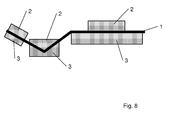
- Fig. 8 shows a schematic sectional view of another embodiment of the method according to the invention.
- first contact plates 2 and a plurality of second contact plates 3 were brought into contact with a metal body 1.
- the contact plates 2, 3 can in this case be arranged both in such a way that the contact plates 2, 3 belonging to a contact plate pair have the same size. However, they can also have different sizes.
- each contact plate 2, 3 may have only one surface that contacts the metal body 1. However, it is also possible for a plurality of surfaces of a contact plate 2, 3 to come into contact with the metal body 1.
Landscapes
- Chemical & Material Sciences (AREA)
- Engineering & Computer Science (AREA)
- Physics & Mathematics (AREA)
- Thermal Sciences (AREA)
- Crystallography & Structural Chemistry (AREA)
- Mechanical Engineering (AREA)
- Materials Engineering (AREA)
- Metallurgy (AREA)
- Organic Chemistry (AREA)
- Heat Treatment Of Articles (AREA)
- Heat Treatments In General, Especially Conveying And Cooling (AREA)
Abstract
Description
Die Erfindung betrifft ein Verfahren zur thermischen Behandlung mindestens eines Metallkörpers. Ferner betrifft die Erfindung eine Vorrichtung zur Durchführung eines derartigen Verfahrens.The invention relates to a method for the thermal treatment of at least one metal body. Furthermore, the invention relates to an apparatus for carrying out such a method.
Als Stand der Technik zur thermischen Behandlung von Metallkörpern sind Wärmeöfen bekannt. Dabei wird der Metallkörper in einem Wärmeofen erwärmt, wobei die thermische Behandlung erfolgt. Bei derartigen Verfahren lassen sich die gewünschten Parameteränderungen im Werkstoff nur bedingt steuern und kontrollieren, da die zeitlichen und thermischen Rahmenbedingungen nicht genau definiert und sicher reproduziert werden können. Dies kann zu unkontrollierbaren Änderungen der Eigenschaften des Blechwerkstoffs führen.As state of the art for the thermal treatment of metal bodies, heat ovens are known. In this case, the metal body is heated in a heating furnace, wherein the thermal treatment takes place. In such methods, the desired parameter changes in the material can be controlled and controlled only conditionally, since the temporal and thermal conditions can not be precisely defined and reproduced safely. This can lead to uncontrollable changes in the properties of the sheet material.
Als weiterer Stand der Technik sind die induktive Erwärmung und die Erwärmung durch Laser bekannt. Beide Verfahren ermöglichen eine lokale thermischen Behandlung an einer definierten Teilfläche eines Metallkörpers. Aufgrund der schnellen lokalen Erwärmung des Werkstoffs ergeben sich Nachteile wie ein Verzug des Metallkörpers und damit Maßabweichungen nach der Erwärmung, eine erschwerte Steuerung und Kontrolle der Temperatur im Erwärmungsfeld aufgrund verzugsbedingt ungleichmäßigem Abstand zwischen Wärmequelle und Blech, eine ungleichmäßige Temperaturverteilung auf der Erwärmungszone, die inhomogene Werkstoffeigenschaften verursacht sowie bei Metallkörpern mit einer Zinkschicht eine partielle oder völlige Zerstörung der Zinkschicht durch Verdampfung.As a further prior art, the inductive heating and the heating by laser are known. Both methods allow a local thermal treatment on a defined partial surface of a metal body. Due to the rapid local heating of the material disadvantages such as a distortion of the metal body and thus deviations after heating arise, a difficult Control and control of the temperature in the heating field due to uneven distance between the heat source and the plate due to distortion, uneven temperature distribution on the heating zone causing inhomogeneous material properties, and partial or complete destruction of the zinc layer by evaporation in metal bodies with a zinc layer.
Der Erfindung liegt die Aufgabe zugrunde, ein im Vergleich zum Stand der Technik verbessertes, insbesondere ein verzugsarmes und/oder hinsichtlich der Temperaturkontrolle verbessertes Verfahren zur thermischen Behandlung von Metallkörpern anzubieten. Ferner soll eine Vorrichtung zur Durchführung des Verfahrens angeboten werden.The invention has for its object to provide a comparison with the prior art improved, in particular a low distortion and / or improved in terms of temperature control process for the thermal treatment of metal bodies. Furthermore, a device for carrying out the method is to be offered.
Diese Aufgabe wird durch ein Verfahren mit den Merkmalen des Patentanspruchs 1 realisiert. Vorteilhafte Ausführungsformen des Verfahrens werden in den Unteransprüchen 2 - 12 realisiert. Für die Vorrichtung wird die Aufgabe durch die Merkmale des Patentanspruchs 13 gelöst.This object is achieved by a method having the features of
Bei dem erfindungsgemäßen Verfahren zur thermischen Behandlung mindestens eines Metallkörpers wird der mindestens eine Metallkörper in seiner Lage fixiert. Es wird eine erste Kontaktplatte mit mindestens einem ersten Flächenabschnitt des Metallkörpers in Kontakt gebracht und eine zweite Kontaktplatte mit mindestens einem zweiten Flächenabschnitt des Metallkörpers in Kontakt gebracht. Dabei sind die Kontaktplatten flächig im wesentlichen oder vollständig entsprechend der Kontur der Flächenabschnitte des Metallkörpers ausgebildet und im Zustand der Kontaktierung mit dem Metallkörper im wesentlichen parallel zueinander verlaufend angeordnet. Außerdem besitzt mindestens eine Kontaktplatte während der Kontaktierung des Metallkörpers eine gegenüber dem Metallkörper höhere oder niedrigere Temperatur.In the method according to the invention for the thermal treatment of at least one metal body, the at least one metal body is fixed in its position. A first contact plate is brought into contact with at least a first surface section of the metal body and a second contact plate is brought into contact with at least one second surface section of the metal body. The contact plates are surface substantially or completely formed according to the contour of the surface portions of the metal body and in the state of contact with the metal body substantially parallel to each other arranged. In addition, at least one contact plate during the contacting of the metal body has a relation to the metal body higher or lower temperature.
Die Temperatur des Metallkörpers gleicht während der Kontaktierung die Temperatur der Kontaktplatte aus. Dies führt zu einer thermischen Behandlung des Metallkörpers. Es ist somit sowohl ein Aufheizen als auch ein Abkühlen des Metallkörpers durch Kontaktplatten möglich. Daneben wird durch die gleichmäßige Temperaturänderung und den Oberflächendruck durch die Kontaktplatten der temperaturbedingte Verzug minimiert.The temperature of the metal body compensates during contacting the temperature of the contact plate. This leads to a thermal treatment of the metal body. It is thus possible both heating and cooling of the metal body by contact plates. In addition, the temperature-induced distortion is minimized by the uniform temperature change and the surface pressure through the contact plates.
Durch das erfindungsgemäße Verfahren ist es möglich eine genau definierte Temperatur in die Bereiche des Metallkörpers, die mit den Kontaktflächen in Verbindung stehen, einzubringen. Dadurch können die sich durch die thermische Behandlung einstellenden Werkstoffeigenschaften sehr exakt und homogen eingestellt werden.By means of the method according to the invention, it is possible to introduce a precisely defined temperature into the regions of the metal body which are in contact with the contact surfaces. As a result, the material properties which arise as a result of the thermal treatment can be adjusted very precisely and homogeneously.
Das erfindungsgemäße Verfahren ist variabel einsetzbar. Insbesondere können die Temperatur, die die Kontaktplatte besitzt bzw. auf die der Metallkörper gebracht wird, sowie die Zeitspanne, für die die Kontaktierung zwischen Kontaktplatten und Metallkörper besteht, nahezu beliebig gewählt werden. So ist es möglich, das erfindungsgemäße Verfahren variabel an die gewünschten Parameter der thermischen Behandlung sowie an den zu behandelnden Werkstoff anzupassen. Insbesondere werden dadurch sowohl thermischen Behandlungen möglich, die zu einer Entfestigung des Werkstoffes führen als auch thermischen Behandlungen, die zu einer Verfestigung führen.The method according to the invention can be used variably. In particular, the temperature which the contact plate has or on which the metal body is brought, as well as the period of time for which the contact between contact plates and metal body, can be chosen almost arbitrarily. It is thus possible to variably adapt the method according to the invention to the desired parameters of the thermal treatment and to the material to be treated. In particular, both thermal treatments are possible, which lead to a softening of the material as well as thermal treatments that lead to a solidification.
Der Kontakt zwischen Metallkörper und Kontaktplatten kann derart ausgebildet sein, dass sich die Kontaktplatten und der Metallkörper direkt berühren. Es kann allerdings auch eine Zwischenschicht, wie etwa ein Kontaktmittel, das den Temperaturausgleich zwischen Kontaktplatte und Metallkörper verbessert, vorhanden sein.The contact between metal body and contact plates may be formed such that the contact plates and the metal body touch directly. However, it may also be an intermediate layer, such as a contact agent, which improves the temperature balance between the contact plate and metal body, be present.
Es kann sowohl nur ein Metallkörper als auch mehrere Metallkörper gleichzeitig zwischen den Kontaktplatten erfaßt werden.It can be detected simultaneously between the contact plates both only a metal body and a plurality of metal body.
Die mit den Kontaktplatten in Verbindung stehenden Flächenabschnitte können sich sowohl über weite Teile des Metallkörpers erstrecken bzw. diesen vollkommen bedecken als auch nur kleine, lokal begrenzte Bereiche des Metallkörpers bilden. Stehen nur lokal begrenzte Bereiche mit den Kontaktplatten in Verbindung kann dadurch eine lokale thermische Behandlung des Metallkörpers durchgeführt werden.The surface portions communicating with the contact plates may extend over or cover completely large portions of the metal body as well as forming only small, localized areas of the metal body. If only locally limited areas are connected to the contact plates, a local thermal treatment of the metal body can be carried out.
In einer vorteilhaften Ausführungsform ist der Metallkörper als Blech oder Blechformteil ausgebildet und der mindestens eine erste Flächenabschnitt befindet sich auf der Blechoberseite und der mindestens eine zweite Flächenabschnitt befindet sich auf der Blechunterseite. Ein derartiges Verfahren führt zu einer sehr homogenen Temperaturverteilung über den gesamten Dickenbereich des Metallkörpers. Dies hat den Vorteil, dass sich durch die thermische Behandlung sehr definierte Werkstoffeigenschaften einstellen lassen, die homogen über den gesamten Flächenabschnitt vorliegen.In an advantageous embodiment, the metal body is formed as a sheet metal or sheet metal part and the at least one first surface portion is located on the upper side of the sheet metal and the at least one second surface portion is located on the underside of the sheet metal. Such a method leads to a very homogeneous temperature distribution over the entire thickness range of the metal body. This has the advantage that can be set by the thermal treatment very defined material properties that are present homogeneously over the entire surface section.
Nach einer besonders vorteilhaften Ausführungsform wird als Metallkörper ein zumindest teilweise mit einer Zinkschicht versehenes Blech oder Blechformteile verwendet. Insbesondere können hochfeste, verzinkte Bleche und Blechformteile aus dem Karosseriebau eingesetzt werden. Bei derartigen Metallkörpern mit einer Zinkschicht verhindert der Kontakt zwischen Metallkörper und Kontaktplatte die Beschädigung bzw. Zerstörung der Zinkschicht.According to a particularly advantageous embodiment, as a metal body is at least partially with a zinc layer provided sheet metal or sheet metal parts used. In particular, high-strength, galvanized sheets and sheet metal parts can be used from the body shop. In such metal bodies with a zinc layer, the contact between metal body and contact plate prevents the damage or destruction of the zinc layer.
In einer weiteren vorteilhaften Ausführungsform wird ein Metallkörper verwendet, der in einem späteren Arbeitsschritt umgeformt wird, und der mindestens eine erste und zweite Flächenabschnitt liegen im oder in der Nähe des später umzuformenden Bereichs. Dadurch ist es möglich, die thermische Behandlung lokal in dem Bereich durchzuführen, der die Durchführbarkeit eines Umformprozesses beeinflusst. Es können so durch die thermische Behandlung lokal Werkstoffeigenschaften erzeugt werden, die den späteren Umformprozess begünstigen. Insbesondere ist so eine lokale Entfestigung dieses Bereichs des Metallkörpers möglich.In a further advantageous embodiment, a metal body is used, which is formed in a later step, and the at least one first and second surface portion are in or near the area to be reformed later. This makes it possible to perform the thermal treatment locally in the area that affects the feasibility of a forming process. It can be generated by the thermal treatment locally material properties that favor the subsequent forming process. In particular, such a local softening of this region of the metal body is possible.
Gemäß einer weiteren Ausführungsform werden die Kontaktplatten auf den Metallkörper gepresst. Dies hat den Vorteil, dass ein Kontakt zwischen Kontaktplatten und Metallkörper besonders sicher gewährleistet wird. Darüber hinaus ist dadurch eine Minimierung der Verzüge besonders wirkungsvoll möglich.According to a further embodiment, the contact plates are pressed onto the metal body. This has the advantage that a contact between contact plates and metal body is ensured particularly secure. In addition, thereby minimizing the delays is particularly effective possible.
In einer weiteren Ausführungsform wird die Temperatur der mindestens einen Kontaktplatte mit erhöhter oder erniedrigterer Temperatur vor und/oder während der Kontaktierung des Metallkörpers mit den Kontaktplatten durch eine Temperaturregeleinrichtung geregelt. So ist es möglich die Temperatur der Kontaktplatte und somit auch die Temperatur des Metallkörpers während der gesamten thermischen Behandlung zu steuern bzw. zu regeln. Insbesondere kann eine derartige Regelungseinrichtung sowohl vor der Kontaktierung die Kontaktplatten vorwärmen, die Kontaktplatten während der Kontaktierung erwärmen, eine gewünschte Temperatur während der Kontaktierung konstant halten oder auch für eine kontrollierte Erniedrigung der Temperatur im Verlauf der Kontaktierung sorgen. Die Regelungseinrichtung kann jedoch auch für eine definierte Kühlung der Kontaktplatten sorgen.In a further embodiment, the temperature of the at least one contact plate with elevated or lowered temperature before and / or during the contacting of the metal body with the contact plates is controlled by a temperature control device. Thus, it is possible the temperature of the contact plate and thus also the temperature of the metal body during the entire thermal treatment control or regulate. In particular, such a control device both preheat prior to contacting the contact plates, heat the contact plates during contacting, keep a desired temperature during contacting constant or provide for a controlled lowering of the temperature in the course of contacting. However, the control device can also provide for a defined cooling of the contact plates.
Gemäß einer weiteren Ausführungsform wird in einem weiteren Verfahrensschritt, nachdem die gewünschte Temperatur zur thermischen Behandlung auf den Metallköper aufgebracht wurde, mindestens eine Kontaktplatte entfernt. Werden alle Kontaktplatten entfernt, führt dies zu einer freien Angleichung der Temperatur des Metallkörpers an die Umgebungstemperatur. Wird eine Kontaktplatte entfernt, so führt dies zu einer teilweisen freien Angleichung der Temperatur des Metallkörpers. In Bereichen des Metallkörpers, die noch mit einer Kontaktplatte in Verbindung stehen, wird der die Temperatur des Metallkörpers hingegen durch die Kontaktplatte beeinflusst. Dadurch wird es möglich, die Ausbildung des Temperaturprofils des Metallkörpers durch das Entfernen einer oder mehrerer Kontaktplatten zu beeinflussen.According to a further embodiment, in a further method step, after the desired temperature has been applied to the metal body for the thermal treatment, at least one contact plate is removed. If all the contact plates removed, this leads to a free alignment of the temperature of the metal body to the ambient temperature. If a contact plate is removed, this leads to a partial free alignment of the temperature of the metal body. In areas of the metal body, which are still associated with a contact plate, the temperature of the metal body, however, is influenced by the contact plate. This makes it possible to influence the formation of the temperature profile of the metal body by removing one or more contact plates.
In einer weiteren Ausführungsform sind die ersten Kontaktplatten und/oder die zweiten Kontaktplatten untereinander mit einem flexiblen Übergangselement verbunden sind. Dadurch können sich die einzelnen Kontaktplatten flexibel an verschiedene Geometrien des Grundkörpers anpassen.In a further embodiment, the first contact plates and / or the second contact plates are interconnected with a flexible transition element. This allows the individual contact plates to adapt flexibly to different geometries of the basic body.
In einer weiteren bevorzugten Ausführungsform wird der Metallkörper in einem ersten Verfahrensschritt erwärmt und in einem anschließenden Verfahrensschritt mit mindestens einer Kontaktplatte in Kontakt gebracht. Dabei besitzt die Kontaktplatte eine gegenüber dem Metallkörper niedrigere Temperatur. Durch die niedrigere Temperatur der Kontaktplatten wird der Metallkörper nach dem Erwärmen gekühlt. Dabei ist diese Kühlung aufgrund der Kontaktplatten hinsichtlich der Temperaturkontrolle gut steuerbar.In a further preferred embodiment, the metal body is heated in a first method step and brought into contact with at least one contact plate in a subsequent method step. In this case, the contact plate has a relation to the metal body lower temperature. Due to the lower temperature of the contact plates, the metal body is cooled after heating. This cooling is well controlled due to the contact plates in terms of temperature control.
Die Erwärmung des Metallkörpers kann dabei durch Kontakt mit Kontaktplatten, die eine höhere Temperatur als der Metallkörper besitzen, erfolgen. Der Metallkörper kann jedoch auch ohne Kontakt mit Kontaktplatten erwärmt werden, beispielsweise mit einem Induktor.The heating of the metal body can be done by contact with contact plates, which have a higher temperature than the metal body. However, the metal body can also be heated without contact with contact plates, for example with an inductor.
Wird die Erwärmung des Metallkörpers durch Kontaktplatten erzielt, so können dieselben Kontaktplatten im anschließenden Verfahrensschritt auch auf eine Temperatur niedriger als die des Metallkörpers gebracht werden und so zur Kühlung dienen. Es können aber auch für die Erwärmung andere Kontaktplatten als für die Kühlung eingesetzt werden.If the heating of the metal body is achieved by contact plates, the same contact plates in the subsequent process step can also be brought to a temperature lower than that of the metal body and thus serve for cooling. But it can also be used for heating other contact plates than for cooling.
In einer weiteren bevorzugten Ausführungsform wird der Metallkörper in einem ersten Verfahrensschritt mit mindestens einer Kontaktplatten in Kontakt gebracht. Dabei besitzt die Kontaktplatte eine gegenüber dem Metallkörper höhere Temperatur. Durch die höhere Temperatur der Kontaktplatten wird der Metallkörper erwärmt. Dabei ist diese Erwärmung aufgrund der Kontaktplatten hinsichtlich der Temperaturkontrolle gut steuerbar. Außerdem wird aufgrund der Kontaktierung der erwärmungsbedingte Verzug minimiert.In a further preferred embodiment, the metal body is brought into contact with at least one contact plates in a first method step. In this case, the contact plate has a relation to the metal body higher temperature. Due to the higher temperature of the contact plates, the metal body is heated. This heating due to the contact plates in terms of temperature control is well controlled. In addition, will minimized due to the contacting of the warp caused by warpage.
Dabei wird bevorzugt die mindestens eine Kontaktplatte, die gegenüber dem Metallkörper eine erhöhte Temperatur besitzt, durch eine Energiequelle auf diese Temperatur erwärmt. Dies kann beispielsweise induktiv oder konduktiv erfolgen.In this case, the at least one contact plate, which has an elevated temperature relative to the metal body, is preferably heated to this temperature by an energy source. This can be done, for example, inductively or conductively.
Die Erwärmung kann entweder zeitlich vor der Kontaktierung mit dem Metallkörper oder während der Kontaktierung erfolgen.The heating can take place either before the contact with the metal body or during the contacting.
Es kann sowohl nur eine Kontaktplatte beheizt werden als auch mehrere Kontaktplatten.It can be heated both only one contact plate as well as several contact plates.
Die Kontaktplatten können auch zeitlich vor der Kontaktierung mit dem Metallkörper in gegenseitigen Kontakt zueinander gebracht werden. Es kann anschließend eine Kontaktplatte aufgeheizt werden. Die Wärme überträgt sich anschließend auf die anderen mit dieser in Kontakt stehenden Kontaktplatten. Anschließend können die Kontaktplatten voneinander getrennt werden und in Kontakt mit dem Metallkörper gebracht werden.The contact plates can also be brought into mutual contact with one another before the contact with the metal body. It can then be heated a contact plate. The heat then transfers to the others with these contact plates in contact. Subsequently, the contact plates can be separated from each other and brought into contact with the metal body.
Die Kontaktplatten können sowohl alle aus dem gleichen Werkstoff als auch aus unterschiedlichen Werkstoffen hergestellt sein. Vorzugsweise bestehen Kontaktplatten, die erwärmt werden, aus einem metallischen Werkstoff, beispielsweise aus Stahl.The contact plates can both be made of the same material as well as of different materials. Preferably, contact plates that are heated, made of a metallic material, such as steel.
Kontaktplatten, die nicht erwärmt werden, können bevorzugt sowohl aus metallischen als auch nicht-metallischen Werkstoffen hergestellt werden. In besonders vorteilhafter Weise werden Kontaktplatten, die nicht erwärmt werden, aus einem Isolationsmaterial hergestellt. Dies hat den Vorteil, dass der Wärmeverlust verringert wird.Contact plates that are not heated may preferably be made of both metallic and non-metallic materials. In a particularly advantageous manner, contact plates, the not heated, made of an insulating material. This has the advantage that the heat loss is reduced.
Die Kontaktplatten können eine Isolationsschicht aufweisen. Auch dadurch kann der Wärmeverlust verringert werden.The contact plates may have an insulating layer. Also, the heat loss can be reduced thereby.
In einer weiteren Ausführungsform wird insbesondere in einem weiteren Verfahrensschritt mindestens eine Kontaktplatte gekühlt. Durch die aktive Kühlung der Kontaktplatten kann die Temperatur des Metallkörpers exakt gesteuert werden. Insbesondere kann dadurch die Abkühlgeschwindigkeit des Metallkörpers genau eingestellt werden. So ist beispielsweise eine Verfestigung des Werkstoffes im Bereich der gekühlten Kontaktplatten möglich.In a further embodiment, in particular in a further method step, at least one contact plate is cooled. By actively cooling the contact plates, the temperature of the metal body can be precisely controlled. In particular, the cooling rate of the metal body can thereby be set precisely. For example, solidification of the material in the area of the cooled contact plates is possible.
Die gekühlten Kontaktplatten können auch Kühlkanäle aufweisen. Dies ermöglicht die Durchleitung von flüssigen oder gasförmigen Kühlmitteln durch die Kontaktplatten, was zu einer besonders exakten Kühlung führt.The cooled contact plates may also have cooling channels. This allows the passage of liquid or gaseous coolants through the contact plates, which leads to a particularly accurate cooling.
Die erfindungsgemäße Vorrichtung ist derart ausgebildet, dass sie zur Durchführung des erfindungsgemäßen Verfahrens nach einem der das Verfahren betreffenden Ansprüche geeignet ist.The device according to the invention is designed such that it is suitable for carrying out the method according to the invention according to one of the claims relating to the method.
Die Erfindung ist anhand von Ausführungsbeispielen in den Zeichnungsfiguren weiter erläutert. Es zeigen:
- Fig.1 1
- eine schematische Schnittdarstellung einer Ausführungsform des erfindungsgemäßen Verfahrens,
- Fig. 2
- eine schematische Schnittdarstellung einer weiteren Ausführungsform des erfindungsgemäßen Verfahrens,
- Fig. 3a
- eine schematische Schnittdarstellung eines ersten Verfahrensschrittes zu einer Temperierung der Kontaktplatten,
- Fig. 3b
- eine schematische Schnittdarstellung eines zweiten Verfahrensschrittes zu einer Anwendung der Kontaktplatten,
- Fig. 3c
- eine schematische Schnittdarstellung eines dritten Verfahrensschrittes zu einer Anwendung der Kontaktplatten,
- Fig. 4
- eine schematische Schnittdarstellung einer weiteren Ausführungsform des erfindungsgemäßen Verfahrens sowie
- Fig. 5
- eine schematische Schnittdarstellung eines weiteren Verfahrensschrittes des erfindungsgemäßen Verfahrens.
- Fig. 6
- eine schematische Schnittdarstellung einer weiteren Ausführungsform des erfindungsgemäßen Verfahrens
- Fig. 7
- eine schematische Schnittdarstellung einer weiteren Ausführungsform des erfindungsgemäßen Verfahrens
- Fig. 8
- eine schematische Schnittdarstellung einer weiteren Ausführungsform des erfindungsgemäßen Verfahrens
- Fig.1 1
- a schematic sectional view of an embodiment of the method according to the invention,
- Fig. 2
- a schematic sectional view of another embodiment of the method according to the invention,
- Fig. 3a
- 1 is a schematic sectional view of a first method step for tempering the contact plates;
- Fig. 3b
- FIG. 2 is a schematic sectional view of a second method step for using the contact plates. FIG.
- Fig. 3c
- 1 is a schematic sectional view of a third method step for an application of the contact plates;
- Fig. 4
- a schematic sectional view of another embodiment of the method according to the invention and
- Fig. 5
- a schematic sectional view of a further process step of the method according to the invention.
- Fig. 6
- a schematic sectional view of another embodiment of the method according to the invention
- Fig. 7
- a schematic sectional view of another embodiment of the method according to the invention
- Fig. 8
- a schematic sectional view of another embodiment of the method according to the invention
Außerdem ist der Metallkörper 1 mit der zweiten Kontaktplatte 3 in Kontakt gebracht worden. Ein zweiter Flächenabschnitt 7 steht mit der zweiten Kontaktplatte 3 in Verbindung.In addition, the
Dabei sind die Kontaktplatten 2,3 flächig entsprechend der Kontur der Flächenabschnitte 6,7 des Metallkörpers 1 ausgebildet und im Zustand der Kontaktierung mit dem Metallkörper 1 parallel zueinander verlaufend angeordnet.In this case, the
Zur Kontaktierung der Kontaktplatten 2,3 mit dem Metallkörper 1 kann entweder nur eine Kontaktplatte oder mehrere Kontaktplatten verschiebbar sein.For contacting the
Die Kontaktierung kann derart gestaltet sein, dass die erste Kontaktplatte 2 und die zweite Kontaktplatte 3 simultan mit dem Metallkörper 1 in Kontakt gebracht werden. Es kann aber auch zunächst eine Kontaktplatte 2 mit dem Metallkörper 1 in Kontakt gebracht werden und erst zeitlich später eine zweite Kontaktplatte 3 hinzukommen.The contact can be designed such that the
Die zweite Kontaktplatte 3 wird bzw. wurde durch eine Energiequelle 5 auf eine gegenüber dem Metallkörper 1 erhöhte oder erniedrigte Temperatur gebracht. Unter Energiequelle 5 wird im weiteren jede Einrichtung verstanden, die zur Kühlung oder Erwärmung von Gegenständen eingesetzt werden kann.The
Die Kontaktplatten 2,3 sind dabei parallel zueinander verlaufend angeordnet. Die zweite Kontaktplatte 3 weist eine Isolationsschicht 8 auf. Durch diese Isolationsschicht 8 kann der Wärme- bzw. Kühlverlust verringert werden.The
Während der Kontaktierung der Kontaktplatten 2,3 mit dem Metallkörper 1 kann die Temperatur des Metallkörpers 1 konstant gehalten werden. Es ist jedoch auch möglich die Temperatur des Metallkörpers im Verlauf der Kontaktierung durch die definierte Änderung der Temperaturen der Kontaktplatten zu variieren. Somit ist eine sehr variable Anpassung des Temperatur-Zeit-Verlaufs möglich.During the contacting of the
Der Temperaturverlauf entlang einer Kontaktplatte 2,3 kann derart ausgebildet sein, dass sich über die gesamte Kontaktplatte 2,3 eine nahezu konstante Temperatur einstellt. Die Kontaktplatte 2,3 kann jedoch auch derart erwärmt oder gekühlt werden, dass sich innerhalb der Kontaktplatte 2,3 Bereiche mit unterschiedlichen Temperaturen bilden. Somit wird es möglich in unterschiedlichen Bereichen des Metallkörpers 1 unterschiedliche Temperatur-ZeitVerläufe zu verwirklichen und damit eine selektive und individuell an den Anwendungszweck angepaßte Temperaturbeaufschlagung einzelner Teilbereiche der Flächenabschnitte 6 und 7 des Metallkörpers zu erzielen.The temperature profile along a
Der mit den Kontaktplatten 2,3 in Kontakt gebrachten erste Flächenabschnitt 6 und zweite Flächenabschnitt 7 des Metallkörpers 1 können die gleiche Größe besitzen. Sie können jedoch auch unterschiedliche Größen besitzen (nicht abgebildet).The
Am Metallkörper 1 kann ein Sensorelement 9 angebracht sein. Vorzugsweise handelt es sich bei dem Sensorelement 9 um ein Temperatursensorelement. Dies ermöglicht die Messung der Temperatur des Metallkörpers. Die auf diese Weise gemessene Temperatur kann beispielsweise als Eingangsgröße für eine Temperaturregeleinrichtung dienen, die den Temperatur-Zeit-Verlauf der thermischen Behandlung steuert bzw. regelt.On the
Das Verfahren kann auch derart ausgestaltet sein, dass gleichzeitig mehrere Metallkörper gleichzeitig im Kontakt mit mindestens einer ersten und/oder einer mindestens einer zweiten Kontaktplatte in Kontakt gebracht werden.The method can also be configured such that a plurality of metal bodies are simultaneously brought into contact with at least one first and / or one at least one second contact plate simultaneously.
Soll der Metallkörper einer Abkühlbehandlung unterzogen werden, können die erste Kontaktplatte 2 und dritte Kontaktplatte 3 derart ausgebildet sein, dass sie gekühlt werden können. Dadurch kann der Metallkörper im Verlauf der thermischen Behandlung exakt abgekühlt werden.If the metal body is to be subjected to a cooling treatment, the
Diese Abkühlung kann dabei so ausgeführt werden, dass beispielsweise eine Verfestigung des Werkstoffes eintritt. Vorzugsweise können in der erste Kontaktplatte 2 und/oder in der zweiten Kontaktplatte 3 Kühlkanäle (nicht dargestellt) vorhanden sein. Durch diese Kühlkanäle kann flüssiges oder gasförmiges Kühlmittel eingeleitet werden.This cooling can be carried out so that, for example, a solidification of the material occurs. Preferably, cooling channels (not shown) may be present in the
Ist während der thermischen Behandlung sowohl eine Aufheiz- als auch eine Abkühlbehandlung vorgesehen, können für beide Teilbehandlungen die gleichen Kontaktplatten 2,3 verwendet werden. Die Abkühlung kann jedoch auch durch Kontaktelemente erfolgen, die sich von den Kontaktplatte 2,3 zur Erwärmung unterscheiden.If both a heating and a cooling treatment are provided during the thermal treatment, the
- 11
- Metallkörpermetal body
- 22
- Erste KontaktplatteFirst contact plate
- 33
- Zweite KontaktplatteSecond contact plate
- 44
- Richtungdirection
- 55
- Energiequelleenergy
- 66
- Erster FlächenabschnittFirst surface section
- 77
- Zweiter FlächenabschnittSecond surface section
- 88th
- Isolationsschichtinsulation layer
- 99
- Sensorelementsensor element
- 1010
- Flexibles ÜbergangselementFlexible transition element
Claims (13)
wobei
in which
wobei
in which
wobei das Blech oder Blechformteil zumindest teilweise mit einer Zinkschicht versehen sind.Method according to claim 2,
wherein the sheet metal or sheet metal part is at least partially provided with a zinc layer.
wobei der Metallkörper (1) in einem späteren Arbeitsschritt umgeformt wird und der mindestens eine erste Flächenabschnitt (6) und zweite Flächenabschnitt (7) im oder in der Nähe des später umzuformenden Bereichs liegen.Method according to one of the preceding claims,
wherein the metal body (1) is formed in a later step and the at least one first surface portion (6) and second surface portion (7) lie in or near the area to be reshaped later.
wobei die Kontaktplatten (2,3) auf den Metallkörper gepresst werden.Method according to one of the preceding claims,
wherein the contact plates (2,3) are pressed onto the metal body.
wobei die Temperatur der mindestens einen Kontaktplatte (2,3) mit höherer oder niedrigerer Temperatur vor und/oder während der Kontaktierung des Metallkörpers (1) mit den Kontaktplatten (2,3) durch eine Temperaturregeleinrichtung geregelt wird.Method according to one of the preceding claims,
wherein the temperature of the at least one contact plate (2,3) with higher or lower temperature before and / or during the contacting of the metal body (1) with the contact plates (2,3) is controlled by a temperature control device.
wobei die Temperatur in mindestens einem Teilbereich der mindestens einen Kontaktplatte (2,3) mit höherer oder niedrigerer Temperatur vor und/oder während der Kontaktierung des Metallkörpers (1) mit den Kontaktplatten (2,3) durch eine Temperaturregeleinrichtung geregelt wird.Method according to one of the preceding claims,
wherein the temperature in at least a portion of the at least one contact plate (2,3) with higher or lower temperature before and / or during the contacting of the metal body (1) with the contact plates (2,3) is controlled by a temperature control device.
wobei in einem weiteren Verfahrensschritt mindestens eine Kontaktplatte (2,3) entfernt wird.Method according to one of the preceding claims,
wherein in a further method step at least one contact plate (2, 3) is removed.
wobei die ersten Kontaktplatten (2) und/oder die zweiten Kontaktplatten (3) untereinander mit einem flexiblen Übergangselement (10) verbunden sind.Method according to one of the preceding claims,
wherein the first contact plates (2) and / or the second contact plates (3) are interconnected with a flexible transition element (10).
wobei insbesondere in einem Verfahrensschritt mindestens eine Kontaktplatte (2,3) gekühlt wird.Method according to one of the preceding claims,
wherein in particular in a method step at least one contact plate (2,3) is cooled.
Priority Applications (1)
| Application Number | Priority Date | Filing Date | Title |
|---|---|---|---|
| EP07112278A EP2014777B1 (en) | 2007-07-11 | 2007-07-11 | Method and device for thermal treatment of metal sheet |
Applications Claiming Priority (1)
| Application Number | Priority Date | Filing Date | Title |
|---|---|---|---|
| EP07112278A EP2014777B1 (en) | 2007-07-11 | 2007-07-11 | Method and device for thermal treatment of metal sheet |
Publications (2)
| Publication Number | Publication Date |
|---|---|
| EP2014777A1 true EP2014777A1 (en) | 2009-01-14 |
| EP2014777B1 EP2014777B1 (en) | 2013-01-09 |
Family
ID=38819974
Family Applications (1)
| Application Number | Title | Priority Date | Filing Date |
|---|---|---|---|
| EP07112278A Active EP2014777B1 (en) | 2007-07-11 | 2007-07-11 | Method and device for thermal treatment of metal sheet |
Country Status (1)
| Country | Link |
|---|---|
| EP (1) | EP2014777B1 (en) |
Cited By (19)
| Publication number | Priority date | Publication date | Assignee | Title |
|---|---|---|---|---|
| EP2182081A1 (en) * | 2008-10-29 | 2010-05-05 | Neue Materialien Bayreuth GmbH | Method and device for thermal treatment of a coated steel sheet body |
| EP2182082A1 (en) * | 2008-10-29 | 2010-05-05 | Neue Materialien Bayreuth GmbH | Method and device for tempering a steel sheet body |
| WO2011000006A2 (en) | 2009-07-03 | 2011-01-06 | Ebner Industrieofenbau Gesellschaft M.B.H. | Method for heating lightweight metal ingots |
| WO2013140072A1 (en) * | 2012-03-23 | 2013-09-26 | Herakles | Holding tool for the heat treatment of metal parts |
| DE102013010936A1 (en) | 2013-06-29 | 2014-04-17 | Daimler Ag | Method for temperature-control of component on light metal base, involves changing temperature at respective temperature-control steps, such that metal sheet is maintained at preset temperature by using contact plate |
| DE102013013732A1 (en) | 2013-08-17 | 2014-04-24 | Daimler Ag | Device, useful for indirectly and inductively heating workpiece e.g. metal sheet, comprises inductively heatable contact element, inductor, and electrically non-conductive supporting unit attached to inductor using non-ferromagnetic nut |
| EP2730665A1 (en) * | 2012-11-07 | 2014-05-14 | Benteler Automobiltechnik GmbH | Thermoforming line and method for producing a thermoformed and press-hardened motor vehicle component |
| DE102012111271A1 (en) | 2012-11-22 | 2014-05-22 | Neue Materialien Bayreuth Gmbh | Method for heat treatment of metal components, involves pre-heating second metallic component by transferring heat during cooling first metal component on heat treatment temperature |
| DE102013021264A1 (en) | 2013-12-14 | 2014-07-17 | Daimler Ag | Device useful for heating of metal plates, comprises heating device which is arranged and designed for direct contact heating of portion of metal plate and comprises heated ceramic element comprising opening formed for direct contact |
| EP2840153A3 (en) * | 2013-08-20 | 2015-04-01 | Benteler Automobiltechnik GmbH | Tempering station with inductor heating |
| DE102014104922A1 (en) | 2014-04-07 | 2015-10-08 | Voestalpine Stahl Gmbh | Apparatus and method for cooling sheet steel blanks |
| WO2015158568A2 (en) | 2014-04-17 | 2015-10-22 | Voestalpine Metal Forming Gmbh | Device and method for pre-cooling sheet steel bars |
| EP2497840B1 (en) | 2011-03-10 | 2017-05-03 | Schwartz GmbH | Oven system and process for partially heating steel blanks |
| EP2730346B1 (en) | 2012-11-07 | 2017-05-10 | Benteler Automobiltechnik GmbH | Thermoforming line for producing thermoformed and press-hardened sheet steel products |
| CN107972312A (en) * | 2017-11-29 | 2018-05-01 | 滁州市华晨软件科技有限公司 | A kind of stamping die using combination pressure pin |
| EP3360621A1 (en) * | 2017-02-14 | 2018-08-15 | Volkswagen Aktiengesellschaft | Method for producing a thermoformed and press-hardened steel sheet component |
| US10266905B2 (en) | 2013-05-24 | 2019-04-23 | Thyssenkrupp Steel Europe Ag | Method and apparatus for hardening a component or semi-finished product |
| EP2907881B1 (en) | 2014-02-07 | 2019-04-24 | Benteler Automobiltechnik GmbH | Hot forming line and method for the preparation of hot formed sheet metal products |
| US10612108B2 (en) | 2014-07-23 | 2020-04-07 | Voestalpine Stahl Gmbh | Method for heating steel sheets and device for carrying out the method |
Families Citing this family (2)
| Publication number | Priority date | Publication date | Assignee | Title |
|---|---|---|---|---|
| JP4825882B2 (en) * | 2009-02-03 | 2011-11-30 | トヨタ自動車株式会社 | High-strength quenched molded body and method for producing the same |
| DE102015101668A1 (en) | 2015-02-05 | 2016-08-11 | Benteler Automobiltechnik Gmbh | Double falling heating and forming tool and method for producing thermoformed and press-hardened motor vehicle components |
Citations (7)
| Publication number | Priority date | Publication date | Assignee | Title |
|---|---|---|---|---|
| DE2003305A1 (en) * | 1969-01-25 | 1970-07-30 | Aisin Seiki | Method and device for partial or local tempering of sheet steel or similar material |
| DD144652A1 (en) * | 1979-06-28 | 1980-10-29 | Klaus Altenburg | UPPER UNIT FOR DIRECTED DAECHER THROUGH THE CENTRAL HEAT |
| DE10333166A1 (en) * | 2003-07-22 | 2005-02-10 | Daimlerchrysler Ag | Press-hardened component and method for producing a press-hardened component |
| DE10341867A1 (en) | 2003-09-09 | 2005-03-31 | Volkswagen Ag | Production of a hardened sheet metal profile comprises deforming the profile from an original shape into an intermediate shape, heating the deformed profile to a hardening temperature, and hardening the heated profile by defined cooling |
| DE102005045340A1 (en) | 2004-10-05 | 2006-04-06 | Corus Aluminium Walzprodukte Gmbh | Process for heat treatment of an aluminum alloy element |
| US7165435B1 (en) * | 2005-07-25 | 2007-01-23 | Gm Global Technology Operations, Inc. | Conduction preheating for hot-formed sheet metal panels |
| WO2007013279A1 (en) | 2005-07-27 | 2007-02-01 | Kikuchi Co., Ltd. | Heating device and heating method |
Family Cites Families (1)
| Publication number | Priority date | Publication date | Assignee | Title |
|---|---|---|---|---|
| DE102007009937A1 (en) * | 2007-03-01 | 2008-09-04 | Schuler Smg Gmbh & Co. Kg | Metal plate shaping heats the plate to a given temperature, which is then clamped between two cooling elements before pressing |
-
2007
- 2007-07-11 EP EP07112278A patent/EP2014777B1/en active Active
Patent Citations (7)
| Publication number | Priority date | Publication date | Assignee | Title |
|---|---|---|---|---|
| DE2003305A1 (en) * | 1969-01-25 | 1970-07-30 | Aisin Seiki | Method and device for partial or local tempering of sheet steel or similar material |
| DD144652A1 (en) * | 1979-06-28 | 1980-10-29 | Klaus Altenburg | UPPER UNIT FOR DIRECTED DAECHER THROUGH THE CENTRAL HEAT |
| DE10333166A1 (en) * | 2003-07-22 | 2005-02-10 | Daimlerchrysler Ag | Press-hardened component and method for producing a press-hardened component |
| DE10341867A1 (en) | 2003-09-09 | 2005-03-31 | Volkswagen Ag | Production of a hardened sheet metal profile comprises deforming the profile from an original shape into an intermediate shape, heating the deformed profile to a hardening temperature, and hardening the heated profile by defined cooling |
| DE102005045340A1 (en) | 2004-10-05 | 2006-04-06 | Corus Aluminium Walzprodukte Gmbh | Process for heat treatment of an aluminum alloy element |
| US7165435B1 (en) * | 2005-07-25 | 2007-01-23 | Gm Global Technology Operations, Inc. | Conduction preheating for hot-formed sheet metal panels |
| WO2007013279A1 (en) | 2005-07-27 | 2007-02-01 | Kikuchi Co., Ltd. | Heating device and heating method |
Cited By (40)
| Publication number | Priority date | Publication date | Assignee | Title |
|---|---|---|---|---|
| EP2182082A1 (en) * | 2008-10-29 | 2010-05-05 | Neue Materialien Bayreuth GmbH | Method and device for tempering a steel sheet body |
| WO2010048951A1 (en) * | 2008-10-29 | 2010-05-06 | Neue Materialien Bayreuth Gmbh | Method and apparatus for controlling the temperature of a steel sheet element |
| WO2010048950A1 (en) * | 2008-10-29 | 2010-05-06 | Neue Materialien Bayreuth Gmbh | Method and apparatus for the thermal treatment of a coated steel sheet element |
| EP2182082B2 (en) † | 2008-10-29 | 2018-01-24 | Neue Materialien Bayreuth GmbH | Method and device for tempering a steel sheet body |
| EP2182081A1 (en) * | 2008-10-29 | 2010-05-05 | Neue Materialien Bayreuth GmbH | Method and device for thermal treatment of a coated steel sheet body |
| WO2011000006A2 (en) | 2009-07-03 | 2011-01-06 | Ebner Industrieofenbau Gesellschaft M.B.H. | Method for heating lightweight metal ingots |
| EP2497840B2 (en) † | 2011-03-10 | 2020-02-26 | Schwartz GmbH | Oven system for partially heating steel blanks |
| EP2497840B1 (en) | 2011-03-10 | 2017-05-03 | Schwartz GmbH | Oven system and process for partially heating steel blanks |
| WO2013140072A1 (en) * | 2012-03-23 | 2013-09-26 | Herakles | Holding tool for the heat treatment of metal parts |
| FR2988401A1 (en) * | 2012-03-23 | 2013-09-27 | Snecma Propulsion Solide | HOLDING TOOLS FOR THERMAL TREATMENT OF METALLIC PARTS |
| CN104245969B (en) * | 2012-03-23 | 2017-03-08 | 赫拉克勒斯公司 | Setting tool for the heat treatment of metal parts |
| RU2630075C2 (en) * | 2012-03-23 | 2017-09-05 | Эйрбас Сафран Лончерз Сас | Fixing tool for thermal processing of metal parts |
| CN104245969A (en) * | 2012-03-23 | 2014-12-24 | 赫拉克勒斯公司 | Holding tool for the heat treatment of metal parts |
| US9903656B2 (en) | 2012-03-23 | 2018-02-27 | Airbus Safran Launchers Sas | Tooling for supporting metal parts during heat treatment |
| DE102012110650C5 (en) * | 2012-11-07 | 2017-12-14 | Benteler Automobiltechnik Gmbh | Hot forming line for the production of hot-formed and press-hardened sheet steel products |
| EP2730665A1 (en) * | 2012-11-07 | 2014-05-14 | Benteler Automobiltechnik GmbH | Thermoforming line and method for producing a thermoformed and press-hardened motor vehicle component |
| DE102012110649C5 (en) | 2012-11-07 | 2018-03-01 | Benteler Automobiltechnik Gmbh | Thermoforming line and method for producing a hot-formed and press-hardened motor vehicle component |
| US9694408B2 (en) | 2012-11-07 | 2017-07-04 | Benteler Automobiltechnik Gmbh | Hot forming line and method for producing a hot formed and press hardened motor vehicle part |
| EP2977472A1 (en) * | 2012-11-07 | 2016-01-27 | Benteler Automobiltechnik GmbH | Tempering station for tempering of sheet metal circuit boards |
| EP2730665B1 (en) | 2012-11-07 | 2017-06-14 | Benteler Automobiltechnik GmbH | Thermoforming line and method for producing a thermoformed and press-hardened motor vehicle component |
| EP2730346B1 (en) | 2012-11-07 | 2017-05-10 | Benteler Automobiltechnik GmbH | Thermoforming line for producing thermoformed and press-hardened sheet steel products |
| EP2730346B2 (en) † | 2012-11-07 | 2020-04-29 | Benteler Automobiltechnik GmbH | Thermoforming line for producing thermoformed and press-hardened sheet steel products |
| DE102012111271A1 (en) | 2012-11-22 | 2014-05-22 | Neue Materialien Bayreuth Gmbh | Method for heat treatment of metal components, involves pre-heating second metallic component by transferring heat during cooling first metal component on heat treatment temperature |
| US10266905B2 (en) | 2013-05-24 | 2019-04-23 | Thyssenkrupp Steel Europe Ag | Method and apparatus for hardening a component or semi-finished product |
| DE102013010936A1 (en) | 2013-06-29 | 2014-04-17 | Daimler Ag | Method for temperature-control of component on light metal base, involves changing temperature at respective temperature-control steps, such that metal sheet is maintained at preset temperature by using contact plate |
| DE102013013732A1 (en) | 2013-08-17 | 2014-04-24 | Daimler Ag | Device, useful for indirectly and inductively heating workpiece e.g. metal sheet, comprises inductively heatable contact element, inductor, and electrically non-conductive supporting unit attached to inductor using non-ferromagnetic nut |
| EP2840153A3 (en) * | 2013-08-20 | 2015-04-01 | Benteler Automobiltechnik GmbH | Tempering station with inductor heating |
| DE102013108972B4 (en) * | 2013-08-20 | 2016-03-17 | Benteler Automobiltechnik Gmbh | Temperature control station with induction heating |
| DE102013021264A1 (en) | 2013-12-14 | 2014-07-17 | Daimler Ag | Device useful for heating of metal plates, comprises heating device which is arranged and designed for direct contact heating of portion of metal plate and comprises heated ceramic element comprising opening formed for direct contact |
| EP2907881B1 (en) | 2014-02-07 | 2019-04-24 | Benteler Automobiltechnik GmbH | Hot forming line and method for the preparation of hot formed sheet metal products |
| EP2907881B2 (en) † | 2014-02-07 | 2021-11-10 | Benteler Automobiltechnik GmbH | Thermoforming line and method for the preparation of thermoformed sheet metal products |
| DE102014104922A1 (en) | 2014-04-07 | 2015-10-08 | Voestalpine Stahl Gmbh | Apparatus and method for cooling sheet steel blanks |
| WO2015155136A1 (en) | 2014-04-07 | 2015-10-15 | Voestalpine Stahl Gmbh | Device and method for cooling steel sheet blanks |
| DE102014104922B4 (en) * | 2014-04-07 | 2017-10-19 | Voestalpine Stahl Gmbh | Apparatus and method for cooling sheet steel blanks |
| DE102014105519B4 (en) * | 2014-04-17 | 2016-05-12 | Schuler Pressen Gmbh | Apparatus and method for precooling sheet steel blanks |
| WO2015158568A2 (en) | 2014-04-17 | 2015-10-22 | Voestalpine Metal Forming Gmbh | Device and method for pre-cooling sheet steel bars |
| DE102014105519A1 (en) | 2014-04-17 | 2015-10-22 | Schuler Pressen Gmbh | Apparatus and method for precooling sheet steel blanks |
| US10612108B2 (en) | 2014-07-23 | 2020-04-07 | Voestalpine Stahl Gmbh | Method for heating steel sheets and device for carrying out the method |
| EP3360621A1 (en) * | 2017-02-14 | 2018-08-15 | Volkswagen Aktiengesellschaft | Method for producing a thermoformed and press-hardened steel sheet component |
| CN107972312A (en) * | 2017-11-29 | 2018-05-01 | 滁州市华晨软件科技有限公司 | A kind of stamping die using combination pressure pin |
Also Published As
| Publication number | Publication date |
|---|---|
| EP2014777B1 (en) | 2013-01-09 |
Similar Documents
| Publication | Publication Date | Title |
|---|---|---|
| EP2014777B1 (en) | Method and device for thermal treatment of metal sheet | |
| EP2182082B1 (en) | Method and device for tempering a steel sheet body | |
| EP2182081B1 (en) | Method for thermal treatment of a coated steel sheet body | |
| EP2907881B2 (en) | Thermoforming line and method for the preparation of thermoformed sheet metal products | |
| EP2324938B1 (en) | Method and thermal recasting assembly for producing a hardened, thermally recast workpiece | |
| DE102005032113B3 (en) | Thermal deformation and partial hardening apparatus, e.g. for automobile components, comprises mold of at least two parts, each formed from segments adjustable to different temperatures | |
| EP2497840B2 (en) | Oven system for partially heating steel blanks | |
| EP2233593B1 (en) | Method and device for thermal recasting of pressure-hardened casting components made of sheet metal | |
| DE102011078075A1 (en) | Features tailored by heat treatment post-processing | |
| EP3072980A1 (en) | Method and device for producing a partially cured moulded part | |
| DE102005055494B3 (en) | Production of a metallic flat product, especially a sheet steel blank, used in the construction of chassis components comprises heating the flat product to a deforming temperature using conduction heating directly before deforming | |
| EP2883967B1 (en) | Method and device for post-treatment of a hardened metallic moulded part by means of electrical resistance heating | |
| EP2730346B1 (en) | Thermoforming line for producing thermoformed and press-hardened sheet steel products | |
| DE102017109613B3 (en) | Hot forming line with tempering station and method of operation | |
| DE102014111501B4 (en) | Hot-forming device and method for producing press-hardened molded parts from sheet steel | |
| DE2003305B2 (en) | Method and device for local tempering of a diaphragm spring | |
| DE102015116014B3 (en) | Process for the production of a starting material for the production of metallic components with regions of different strength | |
| EP3108019B1 (en) | Method for conductively heating sheet metal in pairs, and heating device for carrying out said method | |
| EP2540405B1 (en) | Device for manufacturing circuit boards of varying thicknesses | |
| DE102014104922A1 (en) | Apparatus and method for cooling sheet steel blanks | |
| WO2024105079A1 (en) | Thermally treating a metallic component | |
| EP3985133A2 (en) | Method for making a steel plate and temperature control station | |
| WO2024105076A1 (en) | Thermally treating a metallic component | |
| DE102015122390A1 (en) | Process for the conductive heating of a flat metallic component | |
| WO2024105078A1 (en) | Thermally treating a metallic component |
Legal Events
| Date | Code | Title | Description |
|---|---|---|---|
| PUAI | Public reference made under article 153(3) epc to a published international application that has entered the european phase |
Free format text: ORIGINAL CODE: 0009012 |
|
| AK | Designated contracting states |
Kind code of ref document: A1 Designated state(s): AT BE BG CH CY CZ DE DK EE ES FI FR GB GR HU IE IS IT LI LT LU LV MC MT NL PL PT RO SE SI SK TR |
|
| AX | Request for extension of the european patent |
Extension state: AL BA HR MK RS |
|
| 17P | Request for examination filed |
Effective date: 20090708 |
|
| AKX | Designation fees paid |
Designated state(s): AT BE BG CH CY CZ DE DK EE ES FI FR GB GR HU IE IS IT LI LT LU LV MC MT NL PL PT RO SE SI SK TR |
|
| AXX | Extension fees paid |
Extension state: MK Payment date: 20090714 Extension state: HR Payment date: 20090714 Extension state: RS Payment date: 20090714 Extension state: AL Payment date: 20090714 Extension state: BA Payment date: 20090714 |
|
| 17Q | First examination report despatched |
Effective date: 20090922 |
|
| RIC1 | Information provided on ipc code assigned before grant |
Ipc: C21D 1/673 20060101ALI20120720BHEP Ipc: C21D 1/34 20060101AFI20120720BHEP Ipc: C21D 9/46 20060101ALI20120720BHEP Ipc: B21D 37/16 20060101ALI20120720BHEP |
|
| GRAP | Despatch of communication of intention to grant a patent |
Free format text: ORIGINAL CODE: EPIDOSNIGR1 |
|
| GRAS | Grant fee paid |
Free format text: ORIGINAL CODE: EPIDOSNIGR3 |
|
| GRAA | (expected) grant |
Free format text: ORIGINAL CODE: 0009210 |
|
| AK | Designated contracting states |
Kind code of ref document: B1 Designated state(s): AT BE BG CH CY CZ DE DK EE ES FI FR GB GR HU IE IS IT LI LT LU LV MC MT NL PL PT RO SE SI SK TR |
|
| AX | Request for extension of the european patent |
Extension state: AL BA HR MK RS |
|
| REG | Reference to a national code |
Ref country code: GB Ref legal event code: FG4D Free format text: NOT ENGLISH |
|
| REG | Reference to a national code |
Ref country code: AT Ref legal event code: REF Ref document number: 592809 Country of ref document: AT Kind code of ref document: T Effective date: 20130115 Ref country code: CH Ref legal event code: EP |
|
| REG | Reference to a national code |
Ref country code: IE Ref legal event code: FG4D Free format text: LANGUAGE OF EP DOCUMENT: GERMAN |
|
| REG | Reference to a national code |
Ref country code: DE Ref legal event code: R096 Ref document number: 502007011177 Country of ref document: DE Effective date: 20130307 |
|
| PG25 | Lapsed in a contracting state [announced via postgrant information from national office to epo] |
Ref country code: SI Free format text: LAPSE BECAUSE OF FAILURE TO SUBMIT A TRANSLATION OF THE DESCRIPTION OR TO PAY THE FEE WITHIN THE PRESCRIBED TIME-LIMIT Effective date: 20130109 |
|
| REG | Reference to a national code |
Ref country code: NL Ref legal event code: VDEP Effective date: 20130109 |
|
| REG | Reference to a national code |
Ref country code: LT Ref legal event code: MG4D |
|
| PG25 | Lapsed in a contracting state [announced via postgrant information from national office to epo] |
Ref country code: LT Free format text: LAPSE BECAUSE OF FAILURE TO SUBMIT A TRANSLATION OF THE DESCRIPTION OR TO PAY THE FEE WITHIN THE PRESCRIBED TIME-LIMIT Effective date: 20130109 Ref country code: BG Free format text: LAPSE BECAUSE OF FAILURE TO SUBMIT A TRANSLATION OF THE DESCRIPTION OR TO PAY THE FEE WITHIN THE PRESCRIBED TIME-LIMIT Effective date: 20130409 Ref country code: ES Free format text: LAPSE BECAUSE OF FAILURE TO SUBMIT A TRANSLATION OF THE DESCRIPTION OR TO PAY THE FEE WITHIN THE PRESCRIBED TIME-LIMIT Effective date: 20130420 Ref country code: SE Free format text: LAPSE BECAUSE OF FAILURE TO SUBMIT A TRANSLATION OF THE DESCRIPTION OR TO PAY THE FEE WITHIN THE PRESCRIBED TIME-LIMIT Effective date: 20130109 Ref country code: IS Free format text: LAPSE BECAUSE OF FAILURE TO SUBMIT A TRANSLATION OF THE DESCRIPTION OR TO PAY THE FEE WITHIN THE PRESCRIBED TIME-LIMIT Effective date: 20130509 |
|
| PG25 | Lapsed in a contracting state [announced via postgrant information from national office to epo] |
Ref country code: LV Free format text: LAPSE BECAUSE OF FAILURE TO SUBMIT A TRANSLATION OF THE DESCRIPTION OR TO PAY THE FEE WITHIN THE PRESCRIBED TIME-LIMIT Effective date: 20130109 Ref country code: FI Free format text: LAPSE BECAUSE OF FAILURE TO SUBMIT A TRANSLATION OF THE DESCRIPTION OR TO PAY THE FEE WITHIN THE PRESCRIBED TIME-LIMIT Effective date: 20130109 Ref country code: PT Free format text: LAPSE BECAUSE OF FAILURE TO SUBMIT A TRANSLATION OF THE DESCRIPTION OR TO PAY THE FEE WITHIN THE PRESCRIBED TIME-LIMIT Effective date: 20130509 Ref country code: NL Free format text: LAPSE BECAUSE OF FAILURE TO SUBMIT A TRANSLATION OF THE DESCRIPTION OR TO PAY THE FEE WITHIN THE PRESCRIBED TIME-LIMIT Effective date: 20130109 Ref country code: PL Free format text: LAPSE BECAUSE OF FAILURE TO SUBMIT A TRANSLATION OF THE DESCRIPTION OR TO PAY THE FEE WITHIN THE PRESCRIBED TIME-LIMIT Effective date: 20130109 Ref country code: GR Free format text: LAPSE BECAUSE OF FAILURE TO SUBMIT A TRANSLATION OF THE DESCRIPTION OR TO PAY THE FEE WITHIN THE PRESCRIBED TIME-LIMIT Effective date: 20130410 |
|
| PLBI | Opposition filed |
Free format text: ORIGINAL CODE: 0009260 |
|
| PG25 | Lapsed in a contracting state [announced via postgrant information from national office to epo] |
Ref country code: SK Free format text: LAPSE BECAUSE OF FAILURE TO SUBMIT A TRANSLATION OF THE DESCRIPTION OR TO PAY THE FEE WITHIN THE PRESCRIBED TIME-LIMIT Effective date: 20130109 Ref country code: EE Free format text: LAPSE BECAUSE OF FAILURE TO SUBMIT A TRANSLATION OF THE DESCRIPTION OR TO PAY THE FEE WITHIN THE PRESCRIBED TIME-LIMIT Effective date: 20130109 Ref country code: CZ Free format text: LAPSE BECAUSE OF FAILURE TO SUBMIT A TRANSLATION OF THE DESCRIPTION OR TO PAY THE FEE WITHIN THE PRESCRIBED TIME-LIMIT Effective date: 20130109 Ref country code: DK Free format text: LAPSE BECAUSE OF FAILURE TO SUBMIT A TRANSLATION OF THE DESCRIPTION OR TO PAY THE FEE WITHIN THE PRESCRIBED TIME-LIMIT Effective date: 20130109 Ref country code: RO Free format text: LAPSE BECAUSE OF FAILURE TO SUBMIT A TRANSLATION OF THE DESCRIPTION OR TO PAY THE FEE WITHIN THE PRESCRIBED TIME-LIMIT Effective date: 20130109 |
|
| 26 | Opposition filed |
Opponent name: BENTELER AUTOMOBILTECHNIK GMBH Effective date: 20131009 Opponent name: VOESTALPINE STAHL GMBH Effective date: 20131009 |
|
| PLAX | Notice of opposition and request to file observation + time limit sent |
Free format text: ORIGINAL CODE: EPIDOSNOBS2 |
|
| PG25 | Lapsed in a contracting state [announced via postgrant information from national office to epo] |
Ref country code: CY Free format text: LAPSE BECAUSE OF FAILURE TO SUBMIT A TRANSLATION OF THE DESCRIPTION OR TO PAY THE FEE WITHIN THE PRESCRIBED TIME-LIMIT Effective date: 20130109 |
|
| PG25 | Lapsed in a contracting state [announced via postgrant information from national office to epo] |
Ref country code: IT Free format text: LAPSE BECAUSE OF FAILURE TO SUBMIT A TRANSLATION OF THE DESCRIPTION OR TO PAY THE FEE WITHIN THE PRESCRIBED TIME-LIMIT Effective date: 20130109 |
|
| REG | Reference to a national code |
Ref country code: DE Ref legal event code: R026 Ref document number: 502007011177 Country of ref document: DE Effective date: 20131009 |
|
| BERE | Be: lapsed |
Owner name: NEUE MATERIALIEN BAYREUTH G.M.B.H. Effective date: 20130731 |
|
| PG25 | Lapsed in a contracting state [announced via postgrant information from national office to epo] |
Ref country code: MC Free format text: LAPSE BECAUSE OF FAILURE TO SUBMIT A TRANSLATION OF THE DESCRIPTION OR TO PAY THE FEE WITHIN THE PRESCRIBED TIME-LIMIT Effective date: 20130109 |
|
| REG | Reference to a national code |
Ref country code: CH Ref legal event code: PL |
|
| PLBB | Reply of patent proprietor to notice(s) of opposition received |
Free format text: ORIGINAL CODE: EPIDOSNOBS3 |
|
| REG | Reference to a national code |
Ref country code: IE Ref legal event code: MM4A |
|
| PG25 | Lapsed in a contracting state [announced via postgrant information from national office to epo] |
Ref country code: LI Free format text: LAPSE BECAUSE OF NON-PAYMENT OF DUE FEES Effective date: 20130731 Ref country code: CH Free format text: LAPSE BECAUSE OF NON-PAYMENT OF DUE FEES Effective date: 20130731 Ref country code: BE Free format text: LAPSE BECAUSE OF NON-PAYMENT OF DUE FEES Effective date: 20130731 |
|
| PG25 | Lapsed in a contracting state [announced via postgrant information from national office to epo] |
Ref country code: IE Free format text: LAPSE BECAUSE OF NON-PAYMENT OF DUE FEES Effective date: 20130711 |
|
| REG | Reference to a national code |
Ref country code: AT Ref legal event code: MM01 Ref document number: 592809 Country of ref document: AT Kind code of ref document: T Effective date: 20130711 |
|
| PG25 | Lapsed in a contracting state [announced via postgrant information from national office to epo] |
Ref country code: AT Free format text: LAPSE BECAUSE OF NON-PAYMENT OF DUE FEES Effective date: 20130711 |
|
| PLBP | Opposition withdrawn |
Free format text: ORIGINAL CODE: 0009264 |
|
| PLBD | Termination of opposition procedure: decision despatched |
Free format text: ORIGINAL CODE: EPIDOSNOPC1 |
|
| PG25 | Lapsed in a contracting state [announced via postgrant information from national office to epo] |
Ref country code: MT Free format text: LAPSE BECAUSE OF FAILURE TO SUBMIT A TRANSLATION OF THE DESCRIPTION OR TO PAY THE FEE WITHIN THE PRESCRIBED TIME-LIMIT Effective date: 20130109 Ref country code: TR Free format text: LAPSE BECAUSE OF FAILURE TO SUBMIT A TRANSLATION OF THE DESCRIPTION OR TO PAY THE FEE WITHIN THE PRESCRIBED TIME-LIMIT Effective date: 20130109 |
|
| PG25 | Lapsed in a contracting state [announced via postgrant information from national office to epo] |
Ref country code: LU Free format text: LAPSE BECAUSE OF NON-PAYMENT OF DUE FEES Effective date: 20130711 Ref country code: HU Free format text: LAPSE BECAUSE OF FAILURE TO SUBMIT A TRANSLATION OF THE DESCRIPTION OR TO PAY THE FEE WITHIN THE PRESCRIBED TIME-LIMIT; INVALID AB INITIO Effective date: 20070711 |
|
| PLBM | Termination of opposition procedure: date of legal effect published |
Free format text: ORIGINAL CODE: 0009276 |
|
| STAA | Information on the status of an ep patent application or granted ep patent |
Free format text: STATUS: OPPOSITION PROCEDURE CLOSED |
|
| 27C | Opposition proceedings terminated |
Effective date: 20150608 |
|
| REG | Reference to a national code |
Ref country code: FR Ref legal event code: PLFP Year of fee payment: 10 |
|
| REG | Reference to a national code |
Ref country code: FR Ref legal event code: PLFP Year of fee payment: 11 |
|
| REG | Reference to a national code |
Ref country code: FR Ref legal event code: PLFP Year of fee payment: 12 |
|
| REG | Reference to a national code |
Ref country code: DE Ref legal event code: R082 Ref document number: 502007011177 Country of ref document: DE Representative=s name: BOCKERMANN KSOLL GRIEPENSTROH OSTERHOFF, DE Ref country code: DE Ref legal event code: R081 Ref document number: 502007011177 Country of ref document: DE Owner name: BENTELER AUTOMOBILTECHNIK GMBH, DE Free format text: FORMER OWNER: NEUE MATERIALIEN BAYREUTH GMBH, 95448 BAYREUTH, DE |
|
| REG | Reference to a national code |
Ref country code: GB Ref legal event code: 732E Free format text: REGISTERED BETWEEN 20181203 AND 20181205 |
|
| PGFP | Annual fee paid to national office [announced via postgrant information from national office to epo] |
Ref country code: GB Payment date: 20190719 Year of fee payment: 13 |
|
| GBPC | Gb: european patent ceased through non-payment of renewal fee |
Effective date: 20200711 |
|
| PG25 | Lapsed in a contracting state [announced via postgrant information from national office to epo] |
Ref country code: GB Free format text: LAPSE BECAUSE OF NON-PAYMENT OF DUE FEES Effective date: 20200711 |
|
| PGFP | Annual fee paid to national office [announced via postgrant information from national office to epo] |
Ref country code: FR Payment date: 20210728 Year of fee payment: 15 |
|
| PG25 | Lapsed in a contracting state [announced via postgrant information from national office to epo] |
Ref country code: FR Free format text: LAPSE BECAUSE OF NON-PAYMENT OF DUE FEES Effective date: 20220731 |
|
| PGFP | Annual fee paid to national office [announced via postgrant information from national office to epo] |
Ref country code: DE Payment date: 20230728 Year of fee payment: 17 |