EP2014620A2 - Electrolyser with condenser electrodes in a magnetic field passage for removing salt from seawater - Google Patents
Electrolyser with condenser electrodes in a magnetic field passage for removing salt from seawater Download PDFInfo
- Publication number
- EP2014620A2 EP2014620A2 EP08012445A EP08012445A EP2014620A2 EP 2014620 A2 EP2014620 A2 EP 2014620A2 EP 08012445 A EP08012445 A EP 08012445A EP 08012445 A EP08012445 A EP 08012445A EP 2014620 A2 EP2014620 A2 EP 2014620A2
- Authority
- EP
- European Patent Office
- Prior art keywords
- magnetic field
- electrodes
- electrolyser
- electrolyzer
- electromagnets
- Prior art date
- Legal status (The legal status is an assumption and is not a legal conclusion. Google has not performed a legal analysis and makes no representation as to the accuracy of the status listed.)
- Withdrawn
Links
Images
Classifications
-
- C—CHEMISTRY; METALLURGY
- C02—TREATMENT OF WATER, WASTE WATER, SEWAGE, OR SLUDGE
- C02F—TREATMENT OF WATER, WASTE WATER, SEWAGE, OR SLUDGE
- C02F1/00—Treatment of water, waste water, or sewage
- C02F1/46—Treatment of water, waste water, or sewage by electrochemical methods
- C02F1/4604—Treatment of water, waste water, or sewage by electrochemical methods for desalination of seawater or brackish water
-
- C—CHEMISTRY; METALLURGY
- C02—TREATMENT OF WATER, WASTE WATER, SEWAGE, OR SLUDGE
- C02F—TREATMENT OF WATER, WASTE WATER, SEWAGE, OR SLUDGE
- C02F1/00—Treatment of water, waste water, or sewage
- C02F1/48—Treatment of water, waste water, or sewage with magnetic or electric fields
- C02F1/487—Treatment of water, waste water, or sewage with magnetic or electric fields using high frequency electromagnetic fields, e.g. pulsed electromagnetic fields
-
- C—CHEMISTRY; METALLURGY
- C02—TREATMENT OF WATER, WASTE WATER, SEWAGE, OR SLUDGE
- C02F—TREATMENT OF WATER, WASTE WATER, SEWAGE, OR SLUDGE
- C02F1/00—Treatment of water, waste water, or sewage
- C02F1/48—Treatment of water, waste water, or sewage with magnetic or electric fields
- C02F1/484—Treatment of water, waste water, or sewage with magnetic or electric fields using electromagnets
- C02F1/485—Treatment of water, waste water, or sewage with magnetic or electric fields using electromagnets located on the outer wall of the treatment device, i.e. not in contact with the liquid to be treated, e.g. detachable
-
- C—CHEMISTRY; METALLURGY
- C02—TREATMENT OF WATER, WASTE WATER, SEWAGE, OR SLUDGE
- C02F—TREATMENT OF WATER, WASTE WATER, SEWAGE, OR SLUDGE
- C02F2103/00—Nature of the water, waste water, sewage or sludge to be treated
- C02F2103/08—Seawater, e.g. for desalination
-
- C—CHEMISTRY; METALLURGY
- C02—TREATMENT OF WATER, WASTE WATER, SEWAGE, OR SLUDGE
- C02F—TREATMENT OF WATER, WASTE WATER, SEWAGE, OR SLUDGE
- C02F2303/00—Specific treatment goals
- C02F2303/22—Eliminating or preventing deposits, scale removal, scale prevention
Definitions
- the invention relates to an electrolyzer with capacitor electrodes in the magnetic field for the desalination of seawater and for the desalting of salt solutions according to the preamble of claim 1.
- an electrolyzer For the desalination of seawater to drinking water quality, an electrolyzer is used, in which a plurality of capacitor electrodes are arranged and which is fixed in an asymmetric air gap of a magnetic field passage.
- the capacitor electrodes are energized with high frequency current in such a way that in each case two adjacent capacitor electrodes are connected in parallel to the high frequency generator.
- Each capacitor electrode is in the physical principle of an electric double capacitor whose metal plate consists of ferromagnetic material. The distance between the capacitor electrodes is so small that the electrochemical double layer is maximally utilized for the separation of salts. The kinetics of this separation take place in the electrochemical double layer and in the two fields.
- the seawater is an electrolyte and its main components are sodium at 10 mg / l, magnesium at 1,350 mg / l, sulfur at 885 mg / l, potassium at 380 mg / l, calcium at 400 mg / l, strontium at 8 mg / l, iron at 0.01 mg / l, carbon at 28 mg / l, boron at 4.6 mg / l, nitrogen at 15 mg / l, bromine at 65 mg / l, barium at 0.03 mg / l , Chlorine at 19 mg / l, Fluorine at 1.2 mg / l, Molybdenum at 0.01 mg / l and a whole range of other elements whose concentration is less than one hundredth of a milligram per liter.
- the desalination technology focuses mainly on reverse osmosis, on the membrane process, on the thermal process, on the multi-effect distillation, among others.
- the desalination devices mentioned are robust, technically complex, expensive and in all, the energy consumption is enormous. For example, in reverse osmosis energy consumption is between 4 to 5 kWh per 1 square meter of water.
- the global development of desalination capacity is increasing and the demand for drinking water is rising even faster. The development in this field continues and according to the prior art further methods and devices are known.
- the first technically usable device which is operated in a changing magnetic field and simultaneously in a changing electric field, is in the WO 2006 / 039873A1 and in DE-GM 202004 015 611 Ui released. Furthermore, a device for the electromagnetic desalination of seawater in the DE-GM 20 2006 011 195 Ui described.
- the mentioned electromagnetic methods have demonstrated many economic advantages experimentally and the separation of salts between 35% to 50% has been achieved. The deficit of these devices is in the range of electrical current density at the electrodes and bipolar electrodes, which is defined as Ncm 2.
- the already achieved current density is between 0.3 to 0.5 Ncm 2, which is too low. Furthermore, the capacitive current flowing through the metal electrodes is too low and the Faraday Current is too large, resulting in the formation of overcoat on the metal electrodes. It is only feasible to eliminate this deficit if the capacitive current is increased compared to the Faraday current and this at a much higher current density at the electrodes.
- Seawater is an electrolyte solution and therefore it is subject to this rule in an electrolyzer.
- the double-layer capacitance at the electrodes increases to 50 ⁇ F / cm 2.
- this value depends on the current frequency.
- the cited electromagnetic methods are incapable of fully utilizing the double-layer capacitance and therefore one can not improve the separation factor.
- the efficiency at frequencies between 50 Hz and 400 Hz is not more than 50%.
- the invention is therefore an object of the invention to provide an apparatus for performing a method for desalination of seawater, which is operable with a much higher efficiency than in the previous above and thus a drinking water supply is made possible at much lower cost and that the device for Implementation of the desalting constructively requires no great effort and is cheap to maintain.
- the device for carrying out this task consists of an electrolyzer equipped with capacitive current and equipped with mutually spaced-apart capacitor electrodes, which is arranged in an asymmetrical air gap of an electromagnet or permanent magnet.
- the magnetic field is not homogeneous and the magnetic field gradient increases across the width of the electrolyzer.
- the capacitor electrodes are operated with high-frequency current in such a way that a capacitor electrode is connected to one pole of a high frequency generator and the second adjacent is connected to the other pole.
- the third adjacent Capacitor electrode is connected to the same pole as the first capacitor electrode and the fourth capacitor electrode is connected to the same pole as the second, etc.
- the capacitor electrodes are arranged in the electrolyzer at a small distance from each other that the magnetic field acts perpendicular to the electrolytic current.
- the seawater flows in parallel with the longitudinal axis of the electrolyzer around the capacitor electrodes meandering around.
- the cations and the anions receive an amplified magnetic dipole, causing both electrically charged particles to be pulled in the direction of the rising magnetic field gradient.
- the kinetics of the separation of salts of drinking water is directly proportional to the current density at the capacitor electrodes and to the magnetic flux in the air gap of the magnet. As the intensity of both fields increases, the efficiency increases exponentially.
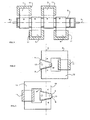
- Fig. 1 in plan view, a plurality of electromagnets in a row, in whose air gap forms a magnetic field passage in which an electrolyzer is arranged.
- FIG. 2 in section, the rear view of an electromagnet, in the asymmetric air gap, an electrolyzer is arranged.
- FIG. 3 in section, the rear view of a second electromagnet, in whose cut in the reverse direction air gap, an electrolyzer is arranged.
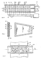
- Fig. 4 in section, the top view of an electrolyzer with capacitor electrodes and electrical circuit.
- Fig. 5 in cross section, a capacitor electrode with capacitor plate and dielectric and two discharge plates.
- Fig. 6 the side view of a capacitor electrode with discharge plate and insulator.
- FIG. 7 in cross-section, an electromagnet with an air gap in which a part of the electrolyzer is arranged.
- the basic principle of the present device is in Fig. 1 illustrated.
- the seawater desalination takes place in an electrolyzer, which is arranged in a magnetic field passage.
- the magnetic field passage consists of a series of electromagnets 1, 2, 3, 4 whose asymmetric air gap is cut so that an asymmetric electrolyzer 5 is pushed in parallel with the imaginary axis 6.
- This construction is in Fig. 2 and Fig. 3 illustrated.
- the air gap 7 on the electromagnet 8 has the shorter side B on the inner side of the electromagnet 8.
- the longer side A is on the outer side of the electromagnet 8.
- Fig. 3 illustrates these design parameters exactly the opposite.
- Gap 9 has the shorter side B on the outside of the electromagnet 10 and the longer side A is on the inner side of the electromagnet.
- the imaginary axis 6 between electromagnets 8 and 10 shows the magnetic field passage between these two.
- the example in Fig. 1 shows, that the device consists of four electromagnets 1, 2, 3, 4, wherein electromagnets 1 and 2 are arranged on one side of the electrolyzer 5 and electromagnets 3 and 4 on the other side.
- the device can be used in Fig. 1 consist of a plurality of electromagnets.
- the magnetic poles of the electromagnets 1, 2, 3, 4 are located close to one another and therefore the entire magnetic field passage forms a balanced magnetic field tunnel.
- Such an arrangement is technically possible because the windings 11 of the adjacent electromagnets are arranged on the other side of the electrolyzer.
- the windings 11 to the electromagnets 1, 2, 3, 4 are energized from band capacitor and with oscillating current.
- the band capacitor is in the DE-OS 199 27 355 A1 described. This is the first application alternative.
- the coils 11 are wound from copper wire and are supplied with direct current.
- the magnetic field is static.
- the magnetic core 12 of all the electromagnets 1, 2, 3, 4 is made of a soft magnetic material, such as e.g. Transformer sheet or a special alloy, for example, from 78% nickel and 22% iron.
- a soft magnetic material such as e.g. Transformer sheet or a special alloy, for example, from 78% nickel and 22% iron.
- highly permeable ferrite such as manifer, is required.
- the cross section of the magnetic core 12 is 50 mm ⁇ 50 mm.
- the asymmetry of the air gap 7 and 9 is 40 mm on the side A and 28 mm on the side B.
- the intensity of the magnetizing current flowing through windings II can be regulated and adjusted as required.
- an electrolyzer 13 is placed from electrically non-conductive material.
- the electrolyzer 13 is illustrated in plan view.
- On the side walls grooves 14 are present in which a plurality of capacitor electrodes 15 is pressed in.
- the capacitor electrodes 15 are connected in parallel to high-frequency generator 18.
- Drains 22, 23, 24 are located on one side of the electrolyzer 13 and their function is to reduce the salt concentrate on the side and thereby keep the concentration gradient low in place.
- the capacitor electrodes 15 in Fig. 4 are close to each other and their distance is between 2 mm and 5 mm.
- the capacitor electrodes 15 should be arranged at a minimum distance from each other, whereby the capacitive electric current between the electrodes is held high.
- capacitor electrode In Fig. 5 the capacitor electrode is illustrated in cross-section. In the middle is capacitor plate 25, which is covered with dielectric 26. Capacitor plate 25 is connected by means of the electrical connection 16 to high-frequency generator 18. On the first outer side of the dielectric 26, a metallic plate electrode 27 is arranged. On the other side of the dielectric 26, a similar metallic plate electrode 28 is attached. The entire components 25, 26, 27, 28 are insulated with electrical insulator 29. Thus produced capacitor electrodes represent the physical principle of a double capacitor, which fulfills a special technical function in the electrolyzer 13.
- Fig. 6 illustrates in side view the in Fig. 5 defined cross section and shows the plate electrodes 27 and the electrical insulator 29.
- the capacitor electrode in Fig. 6 is conically shaped and adapted to the profile of the electrolyzer 13. From a physical point of view, it is important that the capacitor plate 25 be made of soft magnetic material.
- dielectric 26 has a special technical significance and consists of high-quality material, such as perovskites, whose general chemical formula is Ba (Til-x Zr x) 03 or lead magnesium niobate with the formula Pb (M9113 Nb2 / 3) 03. These compounds show no sharp phase transition at the Curie temperature and their dielectric constant is between 10,000 and 50,000.
- Fig. 7 shows in cross section an electromagnet 30 between the poles N, S in air gap 31, a part of electrolyzer 32 is arranged.
- the electrolyzer 32 are in accordance Fig. 4 and FIG. 9 shows capacitor electrodes 33, 34 whose additional physical function is to derive the perpendicular magnetic flux 35 partly in the horizontal direction 36.
- the capacitor plate 25 in Fig. 5 Made of soft magnetic material.
- Such a weak horizontal magnetic flux 36 which is parallel to the electric field 38, has economic significance.
- the horizontal magnetic flux 36 is a physical parameter with the function of increasing the magnetic dipole moment for all charged particles in the electrolyte.
- the electrically charged particles in the horizontal magnetic field 36 and in the horizontal field 38 are forced by known physical law to spiral around the magnetic field lines.
- arrow 37 in FIG Fig. 7 the direction of flow of the electrolyte, which flows around the capacitor electrodes 33, 34 in a meandering manner, which arrow 37 illustrates.
- the capacitor electrodes 33 are fixed to the upper wall and the capacitor electrodes 34 are fixed to the lower wall of the electrolyzer 32.
- the seawater flows, as Arrow 37 illustrates, through the gaps between the electrodes and the Eletkrolyseurwand.
- the electrically charged particles are drawn in the direction of the rising magnetic field gradient according to the principle of a magnetic dipole moment.
- the dipole moment depends on the specific electrical charge of each charged particle. Particles with a larger specific electric charge are pulled with greater force in the direction of the increasing magnetic field gradient than particles with a low specific charge. That's the rule that determines this selective separation.
- the particles in the electrolyte are set in oscillatory motion by a large electric current density and by a large current frequency.
- the current density at the plate electrode 27 in Fla. 6 to 8 Ncm2 is adjustable. This is ten times what can be achieved in the prior art.
- electric current flows through the electrolyzer at a very high frequency an even greater current density can be achieved after the Debye-Falkenhagen effect.
- the difference in specific charge of each particle increases, thereby increasing the selective separation of the salt particles.
- This rule has wide validity and a physical limit is unknown. A mathematical model to define this rule is complicated and outside the text described here.
- the present device is technically straightforward, easy to manufacture and the entire construction consists of commercial materials.
- the device is operated by various physical parameters that are specifically adjustable for specific saline solutions. For example, the device is operated at different current frequencies and that between 50 Hz and 300 kHz. When the device is operated at 10 kHz, the magnetic cores of all the electromagnets are made of nickel-iron-cobalt alloy, and the thickness of the sheets is between 1 mm and 2 mm. In this technical embodiment, current flows through the electrolyzer at the same frequency as the magnetizing current which oscillates in the band capacitor windings 11.
- Fig. 1 illustrates a fundamental unit consisting of four electromagnets 1, 2, 3, 4.
- the frequencies for both electrical currents are adjustable between 1 kHz and 7 kHz and the current density at the electrode plates 27 is 5 Ncm 2.
- Such a unit is technically capable of desalting the seawater to 0.05% by weight. Economical is of importance, the electrical energy consumption of such a unit is less than 2 kWh / 1 .000 1 water.
- the unit in Fig. 1 can be extended with other electromagnets.
- the number of electromagnets is sufficient.
- the separation factor in the electrolyzer 13 in Fig. 4 is negatively affected by the concentration gradient. Because the salt separation already takes place at the first capacitor electrode and increases with each additional capacitor electrode 15, it is necessary that the outflows 22, 23, 24 in Fig. 4 are arranged on the side of the electrolyzer 13. Due to the mentioned outflows, the salt concentrate is continuously reduced.
- the present device is also used in specific areas of the economy and operated at a current frequency of more than 100 kHz. If by the electrolyzer 13 in Fig. 4 electric current flows at such frequency, then the product of current and area is a magnetic dipole moment whose vectorial direction changes rapidly. In such an electrochemical environment, the charged particles are always pulled in the direction of the rising magnetic field gradient, regardless of whether the external magnetic field oscillates or is static. According to this rule, the electromagnets 1, 2, 3, 4 are magnetized with direct current and the windings 11 are then wound from copper wire. Technically, this means that in the entire magnetic field passage a static magnetic field causes the separation of charged particles. In such a static magnetic field passage, the separation factor is enormous and the separation efficiency is very economical.
- the device described here consists of one unit with a drinking water capacity of approx. 1,000 l / h.
- the length of the unit is selected as required.
- Large drinking water systems are assembled from a plurality of such units and operated at suitable locations. The operating costs are compared to the prior art only at 20% and therefore the device described here is economically advantageous.
Abstract
Description
Die Erfindung betrifft einen Elektrolyseur mit Kondensatorelektroden im Magnetfeld zum Entsalzen von Meerwasser und zum Entsalzen von Salzlösungen gemäß Oberbegriff des Patentanspruches 1.The invention relates to an electrolyzer with capacitor electrodes in the magnetic field for the desalination of seawater and for the desalting of salt solutions according to the preamble of claim 1.
Für die Entsalzung von Meerwasser auf Trinkwasserqualität wird ein Elektrolyseur eingesetzt, in dem eine Mehrzahl von Kondensatorelektroden angeordnet sind und der in einem asymmetrischen Luftspalt einer Magnetfeldpassage befestigt ist. Die Kondensatorelektroden werden mit Hochfrequenzstrom bestromt und zwar so, daß jeweils zwei benachbarte Kondensatorelektroden parallel am Hochfrequenzgenerator angeschlossen sind. Jede Kondensatorelektrode ist im physikalischen Prinzip ein elektrischer Doppelkondensator, dessen Metallplatte aus ferromagnetischem Material besteht. Der Abstand zwischen den Kondensatorelektroden ist so gering, daß die elektrochemische Doppelschicht für die Trennung von Salzen maximal genutzt wird. Die Kinetik dieser Trennung findet in der elektrochemischen Doppelschicht und in den zwei Feldern statt.For the desalination of seawater to drinking water quality, an electrolyzer is used, in which a plurality of capacitor electrodes are arranged and which is fixed in an asymmetric air gap of a magnetic field passage. The capacitor electrodes are energized with high frequency current in such a way that in each case two adjacent capacitor electrodes are connected in parallel to the high frequency generator. Each capacitor electrode is in the physical principle of an electric double capacitor whose metal plate consists of ferromagnetic material. The distance between the capacitor electrodes is so small that the electrochemical double layer is maximally utilized for the separation of salts. The kinetics of this separation take place in the electrochemical double layer and in the two fields.
In den Ozeanen steht eine große Menge von Salzwasser mit ca. 3,5 Gew-% Salz zur Verfügung, die bis auf 0,05 Gew-% für die wirtschaftliche Nutzung entsalzt werden muß. Das Meerwasser ist ein Elektrolyt und dessen 1-lauptelemente sind Natrium mit 10 mg/l, Magnesium mit 1.350 mg/l, Schwefel mit 885 mg/l, Kalium mit 380 mg/l, Kalzium mit 400 mg/l, Stronzium mit 8 mg/l, Eisen mit 0,01 mg/l, Carbon mit 28 mg/l, Bor mit 4,6 mg/l, Stickstoff mit 15 mg/l, Brom mit 65 mg/l, Barium mit 0,03 mg/l, Chlor mit 19 mg/l, Fluor mit 1,2 mg/l, Molybdän mit 0,01 mg/l sowie eine ganze Reihe von anderen Elementen, deren Konzentration unter einem hundertstel Milligramm pro Liter vertreten sind.In the oceans, a large amount of salt water with about 3.5% by weight of salt is available, which must be desalted to 0.05% by weight for economic use. The seawater is an electrolyte and its main components are sodium at 10 mg / l, magnesium at 1,350 mg / l, sulfur at 885 mg / l, potassium at 380 mg / l, calcium at 400 mg / l, strontium at 8 mg / l, iron at 0.01 mg / l, carbon at 28 mg / l, boron at 4.6 mg / l, nitrogen at 15 mg / l, bromine at 65 mg / l, barium at 0.03 mg / l , Chlorine at 19 mg / l, Fluorine at 1.2 mg / l, Molybdenum at 0.01 mg / l and a whole range of other elements whose concentration is less than one hundredth of a milligram per liter.
Gemäß dem Stand der Technik sind seit mehr als hundert Jahren unterschiedliche Verfahren und Vorrichtungen zum Entsalzen von Salzlösungen bekannt und manche davon werden an verschiedenen Orten als Anlage zum Meerwasserentsalzen betrieben.In the prior art, different methods and apparatuses for desalting saline solutions have been known for more than one hundred years and some of them are operated at various locations as a facility for seawater desalting.
Die Entsalzungstechnologie konzentriert sich hauptsächlich auf die Umkehrosmose, auf das Membranverfahren, auf das thermische Verfahren, auf die Multieffektdestillation u.a.. Die genannten Entsalzungsvorrichtungen sind robust, technisch aufwendig, teuer und bei allen ist der Energieverbrauch enorm. Zum Beispiel bei der Umkehrosmose liegt der Energieverbrauch zwischen 4 bis 5 kWh pro 1 qm Wasser. Die globale Entwicklung der Entsalzungskapazität steigt und der Bedarf an Trinkwasser steigt noch schneller. Die Entwicklung auf diesem Gebiet geht weiter und gemäß dem Stand der Technik sind weitere Verfahren und Vorrichtungen bekannt.The desalination technology focuses mainly on reverse osmosis, on the membrane process, on the thermal process, on the multi-effect distillation, among others. The desalination devices mentioned are robust, technically complex, expensive and in all, the energy consumption is enormous. For example, in reverse osmosis energy consumption is between 4 to 5 kWh per 1 square meter of water. The global development of desalination capacity is increasing and the demand for drinking water is rising even faster. The development in this field continues and according to the prior art further methods and devices are known.
Vorrichtungen, die die Salzkomponente von der Trinkwasserkomponente mittels gleichzeitiger Einwirkung eines magnetischen und eines elektrischen Wechselfeldes trennen, sind bekannt. Die erste technisch nutzbare Vorrichtung, die in einem wechselnden Magnetfeld und simultan in einem wechselnden elektrischen Feld betrieben wird, ist in der
Gemäß dem Stand der Technik liegt die bereits erreichte Stromdichte zwischen 0,3 bis 0,5 Ncm2, was zu niedrig ist. Ferner ist der durch die Metallelektroden fließende kapazitive Strom zu niedrig und der Faradaysche Strom ist zu groß, was zur Bildung von Deckschichten auf den Metallelektroden führt. Es ist nur dann machbar, dieses Defizit zu beseitigen, wenn der kapazitive Strom gegenüber dem Faradayschen Strom erhöht wird und das bei wesentlich größerer Stromdichte an den Elektroden.According to the prior art, the already achieved current density is between 0.3 to 0.5
Meerwasser ist eine Elektrolytlösung und deshalb ist es in einem Elektrolyseur dieser Regel unterworfen. Bei fließendem Wechselstrom zwischen den Elektroden in dem Elektrolyseur steigt die Doppelschicht-Kapazität an den Elektroden bis 50 µF/cm2. Selbstverständlich ist dieser Wert von der Stromfrequenz abhängig. Gemäß dem Stand der Technik sind die zitierten elektromagnetischen Verfahren nicht imstande, die Doppelschicht-Kapazität völlig zu nutzen und deshalb kann man den Trennfaktor nicht verbessern. Gemäß dem Stand der Technik liegt der Wirkungsgrad bei Frequenzen zwischen 50 Hz und 400 Hz bei nicht mehr als 50%.Seawater is an electrolyte solution and therefore it is subject to this rule in an electrolyzer. When alternating current flows between the electrodes in the electrolyzer, the double-layer capacitance at the electrodes increases to 50 μF /
Der Erfindung liegt demgemäß die Aufgabe zugrunde, eine Vorrichtung zur Durchführung eines Verfahrens zum Entsalzen von Meerwasser zu schaffen, die mit einem wesentlich höheren Wirkungsgrad als bei den bisherigen oben genannten betreibbar ist und damit eine Trinkwasserbereitstellung zu wesentlich günstigeren Kosten ermöglicht wird und daß die Vorrichtung zur Durchführung des Entsalzungsverfahrens konstruktiv keinen großen Aufwand verlangt und günstig zu warten ist.The invention is therefore an object of the invention to provide an apparatus for performing a method for desalination of seawater, which is operable with a much higher efficiency than in the previous above and thus a drinking water supply is made possible at much lower cost and that the device for Implementation of the desalting constructively requires no great effort and is cheap to maintain.
Die Vorrichtung zur Durchführung dieser Aufgabe besteht aus einem mit kapazitivem Strom bestrombaren und mit zueinander distanzierten Kondensatorelektroden bestücktem Elektrolyseur, der in einem asymmetrischen Luftspalt eines Elektromagneten bzw. Permanentmagneten angeordnet ist. In dem asymmetrischen Luftspalt ist das Magnetfeld nicht homogen und der Magnetfeldgradient steigt über die Breite der Elektrolyseurs. Die Kondensatorelektroden werden mit Hochfrequenzstrom betrieben und zwar so, daß eine Kondensatorelektrode an einem Pol eines Hochfrequenzgenerators angeschlossen ist und die zweite benachbarte ist an dem anderen Pol angeschlossen. Die dritte benachbarte Kondensatorelektrode ist an dem gleichen Pol angeschlossen wie die erste Kondensatorelektrode und die vierte Kondensatorelektrode ist an demselben Pol wie die zweite angeschlossen usw.. Nach der vorliegenden Erfindung ist für eine solche Vorrichtung wesentlich, daß die Kondensatorelektroden mit geringem Abstand zueinander in dem Elektrolyseur angeordnet sind und daß das Magnetfeld senkrecht zum elektrolytischen Strom wirkt. Das Meerwasser fließt parallel mit der Längsachse des Elektrolyseurs um die Kondensatorelektroden mäanderartig herum.The device for carrying out this task consists of an electrolyzer equipped with capacitive current and equipped with mutually spaced-apart capacitor electrodes, which is arranged in an asymmetrical air gap of an electromagnet or permanent magnet. In the asymmetric air gap, the magnetic field is not homogeneous and the magnetic field gradient increases across the width of the electrolyzer. The capacitor electrodes are operated with high-frequency current in such a way that a capacitor electrode is connected to one pole of a high frequency generator and the second adjacent is connected to the other pole. The third adjacent Capacitor electrode is connected to the same pole as the first capacitor electrode and the fourth capacitor electrode is connected to the same pole as the second, etc. According to the present invention, it is essential for such a device that the capacitor electrodes are arranged in the electrolyzer at a small distance from each other that the magnetic field acts perpendicular to the electrolytic current. The seawater flows in parallel with the longitudinal axis of the electrolyzer around the capacitor electrodes meandering around.
In dem zwischen den Kondensatorelektroden strömenden kapazitiven Strom sowie in dem senkrecht und parallel wirkenden Magnetfeld bekommen die Kationen und die Anionen einen verstärkten magnetischen Dipol, wodurch beide elektrisch geladenen Teilchen in Richtung des steigenden Magnetfeldgradienten gezogen werden. Die Kinetik der Trennung von Salzen von Trinkwasser ist direkt proportional zur Stromdichte an den Kondensatorelektroden und zum magnetischen Fluß im Luftspalt des Magneten. Bei steigender Intensität von beiden Feldern steigt der Wirkungsgrad exponential.In the capacitive current flowing between the capacitor electrodes and in the perpendicular and parallel magnetic field, the cations and the anions receive an amplified magnetic dipole, causing both electrically charged particles to be pulled in the direction of the rising magnetic field gradient. The kinetics of the separation of salts of drinking water is directly proportional to the current density at the capacitor electrodes and to the magnetic flux in the air gap of the magnet. As the intensity of both fields increases, the efficiency increases exponentially.
Die neue Vorrichtung zu seiner Durchführung wird nachfolgend anhand der zeichnerischen Darstellung von Ausführungsbeispielen näher erläutert.The new device for its implementation will be explained in more detail with reference to the drawing of exemplary embodiments.
Es zeigt schematischIt shows schematically
Das Grundprinzip der vorliegenden Vorrichtung ist in
Die imaginäre Achse 6 zwischen Elektromagnet 8 und 10 zeigt die Magnetfeldpassage zwischen diesen beiden. Das Beispiel in
Bei der zweiten Anwendungsalternative sind die Spulen 11 aus Kupferdraht gewickelt und werden mit Gleichstrom bestromt. In dieser technischen Ausführung ist das Magnetfeld statisch.In the second alternative application, the
Der Magnetkern 12 von allen Elektromagneten 1, 2, 3, 4 besteht aus einem weichen magnetischen Material, wie z.B. Transformatorblech oder einer speziellen Legierung, beispielsweise, aus 78%Nickel und 22% Eisen. Für den Bereich von mehreren Kilohertz des magnetisierenden Stroms ist hochpermeables Ferrit, wie Manifer, erforderlich. Für alle beiden Alternativen beträgt der Querschnitt des Magnetkerns 12 50 mm x 50 mm. Die Asymmetrie des Luftspaltes 7 und 9 ist an der Seite A 40 mm und an der Seite B 28 mm. Die Intensität des durch Wicklungen II fließenden Magnetisierungsstromes ist regulierbar und nach Bedarf einstellbar.The
In dem asymmetrischen Luftspalt 7, 9 in
In dem planaren elektrischen Feld zwischen den Elektroden 15 befindet sich die berühmte chemische Doppelschicht, die nach dem mathematischen Modell von Gouy, Chapman und Stern mit zunehmendem Abstand zwischen den Elektroden in eine diffuse Doppelschicht zerfällt. Aus diesem Grund sollen die Kondensatorelektroden 15 mit minimalem Abstand voneinander angeordent sein, wodurch der kapazitive elektrische Strom zwischen den Elektroden hochgehalten wird.In the planar electric field between the
In
Die wesentlichen variablen physikalischen und technischen Komponenten, aus denen die vorliegende Vorrichtung zur Entsalzung von Meerwasser besteht, sind im obigen Text sowie in den sieben zeichnerischen Darstellungen ausführlich beschrieben. Von Wichtigkeit ist die Kinetik, welche die Trennung der Salzkomponente vom Trinkwasser regelt. Die Kinetik, die diese Trennung regelt, ist der magnetischen Feldstärke in der Magnetfeldpassage, ferner der Länge der Magnetfeldpassage sowie der Kapazität der Kondensatorelektroden und der Frequenz des Stromes direkt proportional. Allerdings gilt diese Regel nur dann, wenn das senkrecht wirkende Magnetfeld einen starken Magnetfeldgradient in dem asymmetrischen Luftspalt aufweist. Durch diesen asymmetrischen Luftspalt und in der gesamten Magnetfeldpassage steigt der Magnetfeldgradient von Seite A zur Seite B. Gerade in diesem Magnetfeldgradient werden die elektrisch geladenen Teilchen nach dem Prinzip eines magnetischen Dipolmoments in Richtung des steigenden Magnetfeldgradienten gezogen. Das Dipolmoment richtet sich nach der spezifischen elektrischen Ladung eines jeden geladenen Teilchens. Teilchen mit größerer spezifischer elektischer Ladung werden mit größerer Kraft in Richtung des steigenden Magnetfeldgradienten gezogen als Teilchen mit niedriger spezifischer Ladung. Das ist die Regel, die diese selektive Trennung bestimmt.The essential variable physical and technical components that make up the present apparatus for desalination of seawater are described in detail in the above text as well as in the seven drawings. Of importance is the kinetics, which regulates the separation of the salt component from the drinking water. The kinetics governing this separation is directly proportional to the magnetic field strength in the magnetic field passage, the length of the magnetic field passage and the capacitance of the capacitor electrodes and the frequency of the current. However, this rule only applies if the perpendicular magnetic field has a strong magnetic field gradient in the asymmetric air gap. Through this asymmetric air gap and in the entire magnetic field passage, the magnetic field gradient increases from side A to side B. Especially in this magnetic field gradient, the electrically charged particles are drawn in the direction of the rising magnetic field gradient according to the principle of a magnetic dipole moment. The dipole moment depends on the specific electrical charge of each charged particle. Particles with a larger specific electric charge are pulled with greater force in the direction of the increasing magnetic field gradient than particles with a low specific charge. That's the rule that determines this selective separation.
Physikalisch ist wichtig, daß die Teilchen in dem Elektrolyt durch eine große elektrische Stromdichte und durch eine große Stromfrequenz in oszillierende Bewegung versetzt werden.Physically, it is important that the particles in the electrolyte are set in oscillatory motion by a large electric current density and by a large current frequency.
Solche Bewegung findet in dem engen Raum zwischen den Kondensatorelektroden statt, d.h., in der Nähe der chemischen Doppelschicht.Such movement takes place in the narrow space between the capacitor electrodes, ie near the chemical double layer.
Gemäß der vorliegenden Vorrichtung ist es technisch machbar, daß die Stromdichte an der Plattenelektrode 27 in Fla. 6 bis 8 Ncm2 einstellbar ist. Das ist ein Zehnfaches dessen, was im Stand der Technik erreichbar ist. Wenn durch den Elektrolyseur mit sehr hoher Frequenz elektrischer Strom fließt, dann ist nach dem Debye-Falkenhagen-Effekt eine noch größere Stromdichte erreichbar. Mit steigender Stromdichte steigt der Unterschied in spezifischer Ladung von jedem Teilchen, wodurch die selektive Trennung von den Salzteilchen immer größer wird. Diese Regel hat breite Gültigkeit und eine physikalische Begrenzung ist nicht bekannt. Ein mathematisches Modell, um diese Regel zu definieren, ist kompliziert und liegt außerhalb des hier beschriebenen Textes.According to the present device, it is technically feasible that the current density at the
Die vorliegende Vorrichtung ist technisch unkompliziert, leicht herstellbar und die gesamte Konstruktion besteht aus kommerziellen Werkstoffen. Betrieben wird die Vorrichtung durch verschiedene physikalische Parameter, die für konkrete Salzlösungen konkret einstellbar sind. Beispielsweise wird die Vorrichtung mit unterschiedlichen Stromfrequenzen betrieben und zwar, zwischen 50 Hz und 300 kHz. Wenn die Vorrichtung bis 10 kHz betrieben wird, dann bestehen die Magnetkerne aller Elektromagneten aus einer Nickel-Eisen-Cobalt-Legierung und die Dicke der Bleche beträgt zwischen 1 mm und 2 mm. In dieser technischen Ausführung fließt durch den Elektrolyseur Strom mit derselben Frequenz wie der Magnetisierungsstrom, der in den Bandkondensatorwicklungen 11 oszilliert.The present device is technically straightforward, easy to manufacture and the entire construction consists of commercial materials. The device is operated by various physical parameters that are specifically adjustable for specific saline solutions. For example, the device is operated at different current frequencies and that between 50 Hz and 300 kHz. When the device is operated at 10 kHz, the magnetic cores of all the electromagnets are made of nickel-iron-cobalt alloy, and the thickness of the sheets is between 1 mm and 2 mm. In this technical embodiment, current flows through the electrolyzer at the same frequency as the magnetizing current which oscillates in the
In
Die Einheit in
Die vorliegende Vorrichtung wird ferner in speziellen Gebieten der Wirtschaft eingesetzt und mit einer Stromfrequenz von mehr als 100 kHz betrieben. Wenn durch den Elektrolyseur 13 in
Die vorliegende Vorrichtung findet eine breite Anwendung in der Wirtschaft und ist in den folgenden Fachgebieten einsetzbar:
- in der Metallurgie
- in der chemischen Industrie
- in der Pharmaindustrie
- in der nuklearen Industrie
- in metallurgy
- in the chemical industry
- in the pharmaceutical industry
- in the nuclear industry
Die hier beschriebene Vorrichtung besteht aus einer Einheit mit einer Trinkwasserkapazität von ca. 1.000 1/Std.. Die Länge der Einheit wird nach Bedarf gewählt. Große Trinkwasseranlagen werden aus einer Mehrzahl von solchen Einheiten zusammengebaut und an geeigneten Orten betrieben. Die Betriebskosten liegen im Vergleich zum Stand der Technik nur bei 20% und deshalb ist die hier beschriebene Vorrichtung wirtschaftlich vorteilhaft.The device described here consists of one unit with a drinking water capacity of approx. 1,000 l / h. The length of the unit is selected as required. Large drinking water systems are assembled from a plurality of such units and operated at suitable locations. The operating costs are compared to the prior art only at 20% and therefore the device described here is economically advantageous.
Claims (5)
Applications Claiming Priority (1)
| Application Number | Priority Date | Filing Date | Title |
|---|---|---|---|
| DE200710031977 DE102007031977A1 (en) | 2007-07-10 | 2007-07-10 | Electrolyzer with capacitor electrodes in a magnetic field passage for desalination of sea water |
Publications (2)
| Publication Number | Publication Date |
|---|---|
| EP2014620A2 true EP2014620A2 (en) | 2009-01-14 |
| EP2014620A3 EP2014620A3 (en) | 2013-10-30 |
Family
ID=39864984
Family Applications (1)
| Application Number | Title | Priority Date | Filing Date |
|---|---|---|---|
| EP08012445.6A Withdrawn EP2014620A3 (en) | 2007-07-10 | 2008-07-10 | Electrolyser with condenser electrodes in a magnetic field passage for removing salt from seawater |
Country Status (2)
| Country | Link |
|---|---|
| EP (1) | EP2014620A3 (en) |
| DE (1) | DE102007031977A1 (en) |
Cited By (3)
| Publication number | Priority date | Publication date | Assignee | Title |
|---|---|---|---|---|
| DE202013004613U1 (en) | 2013-05-16 | 2013-06-28 | Pavel Imris | Apparatus for the electromagnetic desalination of seawater |
| WO2014183740A1 (en) | 2013-05-16 | 2014-11-20 | Pavel Imris | Device for electromagnetic desalination, particularly of seawater |
| EP3542632A4 (en) * | 2016-11-17 | 2020-07-15 | Duvoisin, Charles Adriano | System and method for neutralizing pesticides or similar agents contained in foodstuffs and structural arrangement for implementing same |
Citations (4)
| Publication number | Priority date | Publication date | Assignee | Title |
|---|---|---|---|---|
| DE19927355A1 (en) | 1999-06-16 | 2000-12-21 | Pavel Imris | Transformer with capacitive resistor for operating with high inductivity consists of a low-retentivity magnet core with primary and secondary windings fitted around it. |
| DE202004015611U1 (en) | 2004-10-08 | 2004-12-30 | Imris, Pavel, Dr. | Desalination plant, to convert sea water into drinking water, has vessel to take water continuously as electrolyte with spaced electrode units fed with alternating current to give separate fractions of concentrated/salt-free water |
| WO2006039873A1 (en) | 2004-10-08 | 2006-04-20 | Hydrotech International Ltd. | Method and device for the desalination of in particular seawater with the aid of alternating fields of identical frequencies |
| DE202006011195U1 (en) | 2006-07-20 | 2006-09-28 | Imris, Pavel, Dr. | Electrically-powered sea water desalination plant has electromagnetic core with asymmetric air gap containing electordes |
Family Cites Families (3)
| Publication number | Priority date | Publication date | Assignee | Title |
|---|---|---|---|---|
| US3207684A (en) * | 1964-12-17 | 1965-09-21 | Jr Walter M Dotts | Method for changing the distribution of ions in a solution of an electrolyte |
| FR2063605A5 (en) * | 1969-10-23 | 1971-07-09 | Chabanier Bernard | Separation of ions from an ionised liquid |
| EP0065490A1 (en) * | 1981-05-20 | 1982-11-24 | Jenoptik Jena G.m.b.H. | Method of modifying the salt concentration of liquids |
-
2007
- 2007-07-10 DE DE200710031977 patent/DE102007031977A1/en not_active Withdrawn
-
2008
- 2008-07-10 EP EP08012445.6A patent/EP2014620A3/en not_active Withdrawn
Patent Citations (4)
| Publication number | Priority date | Publication date | Assignee | Title |
|---|---|---|---|---|
| DE19927355A1 (en) | 1999-06-16 | 2000-12-21 | Pavel Imris | Transformer with capacitive resistor for operating with high inductivity consists of a low-retentivity magnet core with primary and secondary windings fitted around it. |
| DE202004015611U1 (en) | 2004-10-08 | 2004-12-30 | Imris, Pavel, Dr. | Desalination plant, to convert sea water into drinking water, has vessel to take water continuously as electrolyte with spaced electrode units fed with alternating current to give separate fractions of concentrated/salt-free water |
| WO2006039873A1 (en) | 2004-10-08 | 2006-04-20 | Hydrotech International Ltd. | Method and device for the desalination of in particular seawater with the aid of alternating fields of identical frequencies |
| DE202006011195U1 (en) | 2006-07-20 | 2006-09-28 | Imris, Pavel, Dr. | Electrically-powered sea water desalination plant has electromagnetic core with asymmetric air gap containing electordes |
Cited By (4)
| Publication number | Priority date | Publication date | Assignee | Title |
|---|---|---|---|---|
| DE202013004613U1 (en) | 2013-05-16 | 2013-06-28 | Pavel Imris | Apparatus for the electromagnetic desalination of seawater |
| WO2014183740A1 (en) | 2013-05-16 | 2014-11-20 | Pavel Imris | Device for electromagnetic desalination, particularly of seawater |
| DE102013008403A1 (en) | 2013-05-16 | 2014-11-20 | Pavel Imris | Apparatus for the electromagnetic desalination of seawater |
| EP3542632A4 (en) * | 2016-11-17 | 2020-07-15 | Duvoisin, Charles Adriano | System and method for neutralizing pesticides or similar agents contained in foodstuffs and structural arrangement for implementing same |
Also Published As
| Publication number | Publication date |
|---|---|
| EP2014620A3 (en) | 2013-10-30 |
| DE102007031977A1 (en) | 2009-01-15 |
Similar Documents
| Publication | Publication Date | Title |
|---|---|---|
| DE69831134T2 (en) | TREATMENT OF WATER | |
| EP0461525B1 (en) | Method and device for substrate coating using a magnetron cathode | |
| DE3124599A1 (en) | "METHOD AND DEVICE FOR SPRAYING WITH MAGNETIC REINFORCEMENT AND FOR COATING A SUBSTRATE" | |
| DE2707144A1 (en) | Cathode sputtering device with magnetic equipment - which can be displaced to move the area of sputtering over an extended surface by relative movement | |
| DE2802689A1 (en) | METHOD FOR CARRYING OUT AN ELECTROLYSIS PROCESS | |
| DE10332789A1 (en) | Membrane assembly, electrodialysis device and method of continuous electrodialytic desalination | |
| DE202006011195U1 (en) | Electrically-powered sea water desalination plant has electromagnetic core with asymmetric air gap containing electordes | |
| DE3012935C2 (en) | Magnetic amplification atomizer | |
| DE202007009615U1 (en) | Electrolyzer with capacitor electrodes in a magnetic field passage for desalination of sea water | |
| EP2327665B1 (en) | Desalination device using selective membranes and magnetic fields | |
| DE102012014266A1 (en) | Magnetic-inductive flowmeter | |
| EP2014620A2 (en) | Electrolyser with condenser electrodes in a magnetic field passage for removing salt from seawater | |
| EP1880980A1 (en) | Device for electromagnetic desalination of sea water | |
| EP0337050A1 (en) | Process and apparatus for the partial or total demineralisation of water | |
| DE1571726A1 (en) | METHOD AND DEVICE FOR CARRYING OUT AN ELECTROLYTIC PROCESS | |
| WO2006039873A1 (en) | Method and device for the desalination of in particular seawater with the aid of alternating fields of identical frequencies | |
| DE202004015611U1 (en) | Desalination plant, to convert sea water into drinking water, has vessel to take water continuously as electrolyte with spaced electrode units fed with alternating current to give separate fractions of concentrated/salt-free water | |
| DE2920780C2 (en) | Magnetic amplification atomizer | |
| DE2361154A1 (en) | DEVICE FOR MULTIPOLAR MAGNETIZATION | |
| DE2212099C3 (en) | Device for the recovery of metal from a liquid containing ions of this metal | |
| DE3741584A1 (en) | ELECTROMAGNETIC FLOW METER WITH ALTERNATING PERMANENT MAGNETIC FIELD | |
| DE3536778A1 (en) | ELECTRODIALYSIS MEMBRANE STACKING UNIT FOR MULTI-CHAMBER PROCESSES | |
| DE102013008403A1 (en) | Apparatus for the electromagnetic desalination of seawater | |
| WO1992020139A2 (en) | Process and device for conveying an at least electrically polarized molecules-containing medium | |
| EP0065490A1 (en) | Method of modifying the salt concentration of liquids |
Legal Events
| Date | Code | Title | Description |
|---|---|---|---|
| PUAI | Public reference made under article 153(3) epc to a published international application that has entered the european phase |
Free format text: ORIGINAL CODE: 0009012 |
|
| AK | Designated contracting states |
Kind code of ref document: A2 Designated state(s): AT BE BG CH CY CZ DE DK EE ES FI FR GB GR HR HU IE IS IT LI LT LU LV MC MT NL NO PL PT RO SE SI SK TR |
|
| AX | Request for extension of the european patent |
Extension state: AL BA MK RS |
|
| RAP1 | Party data changed (applicant data changed or rights of an application transferred) |
Owner name: SCHILDGEN, MORITZ Owner name: IMRIS, PAVEL DR. |
|
| RIN1 | Information on inventor provided before grant (corrected) |
Inventor name: SCHILDGEN, MORITZ Inventor name: IMRIS, PAVEL DR. |
|
| PUAL | Search report despatched |
Free format text: ORIGINAL CODE: 0009013 |
|
| AK | Designated contracting states |
Kind code of ref document: A3 Designated state(s): AT BE BG CH CY CZ DE DK EE ES FI FR GB GR HR HU IE IS IT LI LT LU LV MC MT NL NO PL PT RO SE SI SK TR |
|
| AX | Request for extension of the european patent |
Extension state: AL BA MK RS |
|
| RIC1 | Information provided on ipc code assigned before grant |
Ipc: C02F 1/48 20060101ALI20130920BHEP Ipc: C02F 1/46 20060101AFI20130920BHEP Ipc: C02F 103/08 20060101ALN20130920BHEP Ipc: C02F 1/461 20060101ALI20130920BHEP |
|
| STAA | Information on the status of an ep patent application or granted ep patent |
Free format text: STATUS: THE APPLICATION IS DEEMED TO BE WITHDRAWN |
|
| AKY | No designation fees paid | ||
| REG | Reference to a national code |
Ref country code: DE Ref legal event code: R108 |
|
| 18D | Application deemed to be withdrawn |
Effective date: 20140201 |
|
| REG | Reference to a national code |
Ref country code: DE Ref legal event code: R108 Effective date: 20140709 |