EP1880980A1 - Device for electromagnetic desalination of sea water - Google Patents
Device for electromagnetic desalination of sea water Download PDFInfo
- Publication number
- EP1880980A1 EP1880980A1 EP07014065A EP07014065A EP1880980A1 EP 1880980 A1 EP1880980 A1 EP 1880980A1 EP 07014065 A EP07014065 A EP 07014065A EP 07014065 A EP07014065 A EP 07014065A EP 1880980 A1 EP1880980 A1 EP 1880980A1
- Authority
- EP
- European Patent Office
- Prior art keywords
- electrolyzer
- electrodes
- electromagnet
- air gap
- dielectric
- Prior art date
- Legal status (The legal status is an assumption and is not a legal conclusion. Google has not performed a legal analysis and makes no representation as to the accuracy of the status listed.)
- Withdrawn
Links
Images
Classifications
-
- C—CHEMISTRY; METALLURGY
- C02—TREATMENT OF WATER, WASTE WATER, SEWAGE, OR SLUDGE
- C02F—TREATMENT OF WATER, WASTE WATER, SEWAGE, OR SLUDGE
- C02F1/00—Treatment of water, waste water, or sewage
- C02F1/46—Treatment of water, waste water, or sewage by electrochemical methods
- C02F1/4604—Treatment of water, waste water, or sewage by electrochemical methods for desalination of seawater or brackish water
-
- B—PERFORMING OPERATIONS; TRANSPORTING
- B03—SEPARATION OF SOLID MATERIALS USING LIQUIDS OR USING PNEUMATIC TABLES OR JIGS; MAGNETIC OR ELECTROSTATIC SEPARATION OF SOLID MATERIALS FROM SOLID MATERIALS OR FLUIDS; SEPARATION BY HIGH-VOLTAGE ELECTRIC FIELDS
- B03C—MAGNETIC OR ELECTROSTATIC SEPARATION OF SOLID MATERIALS FROM SOLID MATERIALS OR FLUIDS; SEPARATION BY HIGH-VOLTAGE ELECTRIC FIELDS
- B03C1/00—Magnetic separation
- B03C1/02—Magnetic separation acting directly on the substance being separated
- B03C1/28—Magnetic plugs and dipsticks
- B03C1/288—Magnetic plugs and dipsticks disposed at the outer circumference of a recipient
-
- C—CHEMISTRY; METALLURGY
- C02—TREATMENT OF WATER, WASTE WATER, SEWAGE, OR SLUDGE
- C02F—TREATMENT OF WATER, WASTE WATER, SEWAGE, OR SLUDGE
- C02F1/00—Treatment of water, waste water, or sewage
- C02F1/48—Treatment of water, waste water, or sewage with magnetic or electric fields
- C02F1/481—Treatment of water, waste water, or sewage with magnetic or electric fields using permanent magnets
- C02F1/482—Treatment of water, waste water, or sewage with magnetic or electric fields using permanent magnets located on the outer wall of the treatment device, i.e. not in contact with the liquid to be treated, e.g. detachable
-
- B—PERFORMING OPERATIONS; TRANSPORTING
- B03—SEPARATION OF SOLID MATERIALS USING LIQUIDS OR USING PNEUMATIC TABLES OR JIGS; MAGNETIC OR ELECTROSTATIC SEPARATION OF SOLID MATERIALS FROM SOLID MATERIALS OR FLUIDS; SEPARATION BY HIGH-VOLTAGE ELECTRIC FIELDS
- B03C—MAGNETIC OR ELECTROSTATIC SEPARATION OF SOLID MATERIALS FROM SOLID MATERIALS OR FLUIDS; SEPARATION BY HIGH-VOLTAGE ELECTRIC FIELDS
- B03C2201/00—Details of magnetic or electrostatic separation
- B03C2201/18—Magnetic separation whereby the particles are suspended in a liquid
-
- C—CHEMISTRY; METALLURGY
- C02—TREATMENT OF WATER, WASTE WATER, SEWAGE, OR SLUDGE
- C02F—TREATMENT OF WATER, WASTE WATER, SEWAGE, OR SLUDGE
- C02F1/00—Treatment of water, waste water, or sewage
- C02F1/46—Treatment of water, waste water, or sewage by electrochemical methods
- C02F1/461—Treatment of water, waste water, or sewage by electrochemical methods by electrolysis
- C02F1/46104—Devices therefor; Their operating or servicing
- C02F1/46109—Electrodes
- C02F1/46114—Electrodes in particulate form or with conductive and/or non conductive particles between them
-
- C—CHEMISTRY; METALLURGY
- C02—TREATMENT OF WATER, WASTE WATER, SEWAGE, OR SLUDGE
- C02F—TREATMENT OF WATER, WASTE WATER, SEWAGE, OR SLUDGE
- C02F1/00—Treatment of water, waste water, or sewage
- C02F1/46—Treatment of water, waste water, or sewage by electrochemical methods
- C02F1/461—Treatment of water, waste water, or sewage by electrochemical methods by electrolysis
- C02F1/46104—Devices therefor; Their operating or servicing
- C02F1/46109—Electrodes
- C02F2001/46128—Bipolar electrodes
-
- C—CHEMISTRY; METALLURGY
- C02—TREATMENT OF WATER, WASTE WATER, SEWAGE, OR SLUDGE
- C02F—TREATMENT OF WATER, WASTE WATER, SEWAGE, OR SLUDGE
- C02F1/00—Treatment of water, waste water, or sewage
- C02F1/46—Treatment of water, waste water, or sewage by electrochemical methods
- C02F1/461—Treatment of water, waste water, or sewage by electrochemical methods by electrolysis
- C02F1/46104—Devices therefor; Their operating or servicing
- C02F1/46109—Electrodes
- C02F2001/46133—Electrodes characterised by the material
- C02F2001/46138—Electrodes comprising a substrate and a coating
-
- C—CHEMISTRY; METALLURGY
- C02—TREATMENT OF WATER, WASTE WATER, SEWAGE, OR SLUDGE
- C02F—TREATMENT OF WATER, WASTE WATER, SEWAGE, OR SLUDGE
- C02F1/00—Treatment of water, waste water, or sewage
- C02F1/46—Treatment of water, waste water, or sewage by electrochemical methods
- C02F1/461—Treatment of water, waste water, or sewage by electrochemical methods by electrolysis
- C02F1/46104—Devices therefor; Their operating or servicing
- C02F1/46109—Electrodes
- C02F2001/46152—Electrodes characterised by the shape or form
- C02F2001/46157—Perforated or foraminous electrodes
-
- C—CHEMISTRY; METALLURGY
- C02—TREATMENT OF WATER, WASTE WATER, SEWAGE, OR SLUDGE
- C02F—TREATMENT OF WATER, WASTE WATER, SEWAGE, OR SLUDGE
- C02F2103/00—Nature of the water, waste water, sewage or sludge to be treated
- C02F2103/08—Seawater, e.g. for desalination
Definitions
- the invention relates to a device for desalting seawater and for desalting salt solutions according to the preamble of claim 1.
- an electromagnet is used in the magnetic core an asymmetrical air gap is arranged.
- an electrolyzer is attached, which is provided with two opposing and coated with a dielectric discharge electrodes
- the discharge electrodes are energized with high-frequency current, between these two at least one bipolar dielectric-coated electrode is disposed and the space between the discharge and bipolar electrodes filled with spherical granules of dielectric
- the windings on the electromagnet consist of band capacitor and are energized with high frequency current.
- the first technical usable device which is operated in the magnetic field and simultaneously in an electric field, is in the WO 2006/039873 A1 and in DE-GM 20 2004 015 611 U1 released.
- the currents flowing through the electrodes and bipolar electrodes are mainly Faraday currents and only a fraction is capacitive current. Experimental results have proved that it is the capacitive current that is the most important physical parameter causing the separation of cations and anions. Faraday currents are due to electrode reactions, which has economically negative effects at low current frequency. Pure capacitive current oscillates only in the thin Helmholtz double layer, which is located on the metal electrodes and bipolar electrodes.
- the WO 2006/039873 A1 have shown the measurement results, in the cells between the bipolar electrodes is only diffusion current. Diffusion current in the electrolyte solution has no effect on the separation of ions. An increase in the capacitive current leads to an improvement in efficiency, ie, the cations and anions are conducted with greater force to one side of the electrolyzer.
- the efficiency of in the WO 2006/039873 A1 described device is of the order of 12% to 15%, which is still low. If the current flowing through the electrolyzer were purely capacitive, the efficiency would reach 60% to 80%.
- the capacitive current flowing through metal electrodes serves to reload the Helmholtz double layer. In contrast, Faraday currents are limited to electrode reactions, which leads to the formation of cover layers on the electrodes.
- the invention is therefore an object of the invention to provide a device for desalinating seawater, which is operated with a much higher efficiency than the previous abovementioned devices, in order to enable a drinking water supply at much cheaper cost, mainly in the conservation of energy, and their Maintenance is cheap.
- the device for carrying out this task consists of an electromagnet in whose magnetic core there is an asymmetrical air gap, in which an electrolyzer is arranged, in which at least two opposing discharge electrodes coated with dielectric are present.
- the magnetic field is not homogeneous.
- the seawater flows in parallel with the longitudinal axis of the electrolyzer through the openings on the discharge and bipolar electrodes and between the granules to the drains located at the rear of the electrolyzer.
- the cations and anions receive an amplified magnetic dipole, whereby both electrically charged particles are drawn in the direction of the rising magnetic field gradient.
- Fig. 2 increases in cross-section, which is parallel to the line I-II, arranged between the magnetic poles electrolyzer;
- Fig. 3 in section the front view of the electrolyzer
- FIG. 5 shows a cross section of a discharge electrode with a coating of dielectric
- Figure 6 is a side view of a bipolar electrode with openings for the Merrwasser matfluß.
- Fig. 7 in section an embodiment of the band capacitor.
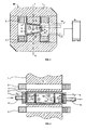
- the basic principle of the present device is illustrated in FIG .
- Seawater desalination takes place in an electric field and in a perpendicularly superimposed magnetic field generated by the electromagnet EM.
- the electromagnet EM consists of a magnetic core 1 and windings 2.
- the windings 2 are made of band capacitor.
- the magnetic core 1 is made of a soft magnetic material such as transformer btech or ferrite.
- transformer plate For frequencies in the range of several kilohertz, highly permeable ferrite, such as manifer, is required.
- an asymmetrical air gap 3 is worked out. The asymmetry is that width A of the air gap 3 is larger than side B.
- Width A should be 50 mm and width B should be 40 mm.
- the cross-sectional areas of the magnetic poles N, S should be on the order of 140 cm 2 .
- an electrolyzer 4 is placed from electrically non-conductive material, in which two discharge electrodes (not shown in Fig. 1 ) arranged and connected by the electrical connections 7 and 8 on the high-frequency generator 9.
- the discharge electrodes in the circuit with the magnet windings 2 through terminals 10, 11 are connected in series to the high-frequency generator 9 .
- drinking water drain 12 is illustrated. Through the outflows 13 and 14 flows out of the electrolyzer, the salt concentrate.
- Fig. 2 illustrates the basic principle of the device illustrated in a cross-section which is parallel to the line I-II (Fig. 1) between which magnetic poles N, S the electrolyzer 4 is arranged, in which electrodes 5 and 6 are fixed.
- the discharge electrodes 5, 6 are, in principle, coated with a good dielectric metal plates.
- the metal plates are the electrical connections 7, 8 to the high frequency generator 9 is connected.
- between the discharge electrodes 5,6 additional components are disposed, such as a plurality of bipolar electrodes 15, Further, the space between the discharge electrodes 5, 6 and the bipolar electrodes 15 is filled with granular granules 16.
- the material of the granules 16 is also a good dielectric such as ceramics of the type: perovskite general chemical formula is Ba (Ti 1 - x Zrx) 03.
- the diameter of the granules is between 6-11 mm and its dielectric constant is between 10,000 and 50,000.
- the discharge electrodes 5 and 6 and bipolar electrodes 15 are also coated with the same or a similar dielectric constant material.
- the seawater is introduced by inflow 17 in the electrolyzer 4 by means of a pump (not shown in Fig. 1 ). Arrow 18 in Fig. 2 shows the direction of flow of seawater. Drinking water drain 12 is attached to the rear of the electrolyzer. At the electrodes 5, 6 and at the bipolar electrodes 15 there are openings 19 through which the seawater flows.
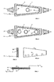
- Fig. 3 shows in section the front view of the electrolyzer 4 with the discharge electrode 5 and the seawater supply 17.
- the discharge electrode 5 is fixed and connected by connection 7 to high-frequency generator 9 .
- fastening parts 21 of the electrolyzer 4 is attached to the structure of the electromagnet EM.
- FIG. 4 shows in section the rear view of the electrolyzer 4.
- the drinking water flows through drains 13, 14 , the salt concentrate flows out of the electrolyzer 4 out.
- Discharge electrode 6 is connected through the electrical connection 8 to high-frequency generator 9 .
- the other symbols in FIG. 4 are the same as in FIG. 3.
- Fig. 5 shows in cross section a discharge electrode 5 which is coated with dielectric 22.
- the dielectric constant should be between 10,000 and 50,000.
- Discharge electrode 5 is connected to high-frequency generator 9 via electrical connection 8 .
- Fig. 6 shows in side view a bipolar electrode 15 with the openings 19 through which the seawater flows.
- the metal plate must be thinly and homogeneously coated on the surface with the high dielectric constant ceramic material. This also counts for the inner walls of the openings 19th
- Fig. 7 shows in section a band capacitor, which consists in principle of two metal foils 23, 24 and dielectric 25 is essential here that an electrical terminal 26 at the beginning of the metal foil 24 and the second electrical terminal 27 is attached to the end of the metal foil 23 .
- the charge and discharge current which is also called wattless current, flows from high-frequency generator 9 through terminal 25 to the metal foil 24 and then as a displacement current through dielectric 25 through metal foil 23 to the electrical terminal 27 , which is also connected to high-frequency generator 9 . That counts for the first half period of the alternating current. In the second half period, the band capacitor is discharged and the entire electric charge flows back to the high frequency generator.
- the wattless current in windings 2 ( Figure 1) produces a magnetic field which for the desalination of seawater according to the invention is the fundamental physical component in the asymmetric gap 3 of the electromagnet EM ( Figure 1) a nonhomogeneous magnetic field.
- the magnetic field strength is greater than on page A. In such an arrangement, one can operate the magnetic field in the air gap at arbitrary frequencies. This is not possible when the windings 2 are wound from wire.
- the following example shows some parameters for the manufacture of the strip capacitor:
- the metal foils 23, 24 (FIG. 7) are made of copper with a thickness of 0.2 mm.
- the width of the metal foils 23 , 24 is 35 mm.
- Dielectric 25 has at least the number one hundred.
- the band capacitor (Fig. 1) is in the DE-OS 199 27 355 A1 described as a novel transformer.
- the capacitive resistance X c ' which is referred to as reactance, is very small at high frequencies and at high capacitances and is defined by equation [2]
- This resistor does not deprive the circuit of energy.
- the electrically charged particles move in the direction according to the principle of magnetic susceptibility pulled the rising magnetic field gradient.
- the force acting on the cations and anions has the dimension of a magnetic dipole moment per unit volume.
- Susceptibility is negative for diamagnetic, negative for substances and positive for paramagnetic substances.
- the accumulation of particles and charges of various cations and anions in the electrolyzer depends on the number and polarity of the susceptibility.
- the paramagnetic, electrically charged particles are pulled in the magnetic field gradient to the side B of the electrolyzer 4 and the dlamagnetic particles are pressed to the side A. This physical phenomenon controls the efficiency of the device described herein.
- the high frequency generator 9 (Fig. 1) supplies alternating current in the electromagnetic circuit at a frequency between 50 Hz and several megahertz.
- a second technical alternative is that the generator 9 provides in the circuit high frequency monopolar pulses.
- the monopulse pulses polarize the dielectric-coated electrodes 5, 6, 15 in one direction, which is of economic importance to the chemical industry and the pharmaceutical industry.
- the device described here consists of one unit, the drinking water in the order of 1,000 1 / h. separated from seawater. Large plants are assembled from a plurality of such units and operated at suitable locations. The operating costs have dropped below 20% compared to the prior art, for which reason the present device for the electromagnetic desalination of seawater is economically advantageous.
Abstract
Description
Die Erfindung betrifft eine Vorrichtung zum Entsalzen von Meerwasser und zum Entsalzen von Salzlösungen gemäß Oberbegriff des Patentanspruches 1.The invention relates to a device for desalting seawater and for desalting salt solutions according to the preamble of
Für die Entsalzung von Meerwasser auf Trinkwasserqualität wird ein Elektromagnet eingesetzt, in dessen Magnetkern ein asymetrischer Luftspalt angeordnet ist. In diesem Luftspalt ist ein Elektrolyseur befestigt, der mit zwei ge genüberstehenden und mit einem Dielektrikum beschichteten Entladungs- elektroden versehen ist Die Entladungselektroden werden mit Hochfrequenzstrom bestromt, wobei zwischen diesen beiden mindestens eine bipolare mit Dielektrikum beschichtete Elektrode angeordnet ist und der Raum zwischen den Entladungs- und bipolaren Elektroden mit kugelartigern Granulat aus Dielektrikum ausgefüllt ist Die Wicklungen an dem Elektromagnet bestehen aus Bandkondensator und werden mit Hochfrequenzstrom bestromt.For the desalination of sea water to drinking water quality, an electromagnet is used in the magnetic core an asymmetrical air gap is arranged. In this air gap, an electrolyzer is attached, which is provided with two opposing and coated with a dielectric discharge electrodes The discharge electrodes are energized with high-frequency current, between these two at least one bipolar dielectric-coated electrode is disposed and the space between the discharge and bipolar electrodes filled with spherical granules of dielectric The windings on the electromagnet consist of band capacitor and are energized with high frequency current.
In den Ozeanen steht eine enorme Menge an Salzwasser mit ca. 3,5 Gew.-% Salz zur Verfügung, die bis auf 0.05 Gew.-% für die wirtschaftliche Nutzung entsalzt werden muß. Gemäß dem Stand der Technik sind seit langem unterschiedliche Verfahren und Vorrichtungen zum Entsalzen von Meerwasser bekannt, die an verschiedenen Orten als Anlagen betrieben werden. Die Entsalzungstechnologie hat mit dem Verdampfungsverfahren und dem Gefrierverfahren bis zur auf Elektrodialyse oder Elektroosmose basierende Verfahren begonnen. Die Umkehrosmose ist bis zu großen Anlagen entwickelt, die mit einer komplizierten Hydraulik und Drucksystemen betrieben werden, wodurch der Energieverbrauch enorm hoch ist. Die membrantechnische Meerwasserentsalzung ist ebenfalls eine energieintensive Technologie und wird mit komplizierten Ultrafiltrations-Modulen betrieben. Die hohen Lebenszykluskosten, der niedrige Wirkungsgrad, enorm hohe Investitionen sowie teure Wartung sind wirtschaftliche Nachteile, die durch zusätzliche Forschung nicht zu beseitigen sind.In the oceans, an enormous amount of salt water with about 3.5 wt .-% salt is available, which must be desalted to 0.05 wt .-% for economic use. The prior art has long disclosed various methods and apparatus for desalinating seawater which operate at various locations as installations. Desalination technology has begun with the evaporation process and freezing process to electrodialysis or electroosmosis based processes. Reverse osmosis is developed up to large plants, which are operated with a complicated hydraulic and pressure systems, whereby the energy consumption is enormously high. Membrane desalination is also an energy-intensive technology and is operated with complicated ultrafiltration modules. The high life-cycle costs, the low efficiency, enormous investments and expensive maintenance are economic disadvantages that can not be eliminated by additional research.
Gemäß dem Stand der Technik sind weitere Verfahren und Vorrichtungen bekannt, die mittels gleichzeitiger Einwirkung eines magnetischen und eines elektrischen Wechselfeldes die Salzkomponente von der Trinkwasserkomponente trennen. In den
Die erste technische nutzbare Vorrichtung, die im Magnetfeld und simultan in einem elektrischen Feld betrieben wird, ist in der
Gemäß der
Meerwasser ist eine Elektrolytlösung und deshalb ist es dieser Regel unterworfen. Gemäß der Meßergebnisse steigt die Doppelschichtkapazität bei zyklischer Voltametrie bis zu 54 µF/cm2 . Selbstverständlich ist dieser Wert von der Stromfrequenz abhängig. Die Doppelschichtkapazität hat andere Werte, wenn der Elektrolyseur in einem Luftspalt eines Elektromagneten angeordnet ist.Seawater is an electrolyte solution and therefore it is subject to this rule. According to the measurement results, the double-layer capacitance increases with cyclic voltammetry up to 54 μF / cm 2 . Of course, this value depends on the current frequency. The bilayer capacity has different values when the electrolyzer is placed in an air gap of an electromagnet.
Der Erfindung liegt demgemäß die Aufgabe zugrunde, eine Vorrichtung zum Entsalzen von Meerwasser zu schaffen, die mit einem wesentlich höheren Wirkungsgrad als die bisherigen obengenannten Vorrichtungen betrieben wird, um damit eine Trinkwasserbereitstellung zu wesentlich günstigeren Kosten, hauptsächlich beim Sparen von Energie, zu ermöglichen und deren Wartung günstig ist.The invention is therefore an object of the invention to provide a device for desalinating seawater, which is operated with a much higher efficiency than the previous abovementioned devices, in order to enable a drinking water supply at much cheaper cost, mainly in the conservation of energy, and their Maintenance is cheap.
Die Vorrichtung zur Durchführung dieser Aufgabe besteht aus einem Elektromagnet, in dessen Magnetkern sich ein asymetrischer Luftspalt befindet, in dem ein Elektrolyseur angeordnet ist in welchem mindestens zwei gegenüberstehende mit Dielektrikum beschichtete Entladungselektroden vorhanden sind. In dem asymetrischen Luftspalt ist das Magnetfeld nicht homogen. Nach der vorliegenden Erfindung ist für eine solche Vorrichtung wesentlich, daß zwischen den zwei Entladungselektroden mindestens eine bipolare, mit Dielektrikum beschichtete Elektrode angeordnet ist und daß der Raum zwischen den Elektroden mit kugelförmigem Granulat mit höherer Dielektrizitätskonstante ausgefüllt ist. Das Meerwasser fließt parallel mit der Längsachse des Elektrolyseurs und zwar durch die Öffnungen an den Entladungs- und bipolaren Elektroden und zwischen dem Granulat zu den Abflüssen, die an der Rückseite des Elektrolyseurs angeordnet sind.The device for carrying out this task consists of an electromagnet in whose magnetic core there is an asymmetrical air gap, in which an electrolyzer is arranged, in which at least two opposing discharge electrodes coated with dielectric are present. In the asymmetric air gap, the magnetic field is not homogeneous. According to the present invention, it is essential for such a device that at least one bipolar, dielectric-coated electrode is disposed between the two discharge electrodes and that the space between the electrodes is filled with spherical granules of higher dielectric constant. The seawater flows in parallel with the longitudinal axis of the electrolyzer through the openings on the discharge and bipolar electrodes and between the granules to the drains located at the rear of the electrolyzer.
Durch zwei Abflüsse fließt ein hochkonzentriertes Salzkonzentrat, das aus Merrwasser-Salzen besteht und aus dem dritten Abfluß der zwischen den beiden Abflüssen angeordnet ist, fließt Trinwasser heraus. Voraussetzung ist, daß das Dielektrikum aus einem Material mit großer Dielektrizitätskonstante besteht.Through two drains flows a highly concentrated salt concentrate, which consists of Merrwasser salts and from the third outflow which is located between the two drains, flows out of Trinwasser. The prerequisite is that the dielectric consists of a material with a high dielectric constant.
In dem im Elektrolyseur strömenden kapazitiven Strom sowie in dem senkrecht wirkenden Magnetfeld bekommen die Kationen und Anionen einen verstärkten magnetischen Dipol, wodurch beide elektrisch geladenen Teilchen in Richtung des steigenden Magnetfeldgradienten gezogen werden.In the capacitive current flowing in the electrolyzer and in the perpendicular magnetic field, the cations and anions receive an amplified magnetic dipole, whereby both electrically charged particles are drawn in the direction of the rising magnetic field gradient.
Die neue Vorrichtung zu seiner Durchführung wird nachfolgend anhand der zeichnerischen Darstellung von Ausführungsbeispielen näher erläutert.The new device for its implementation will be explained in more detail with reference to the drawing of exemplary embodiments.
Es zeigt schematischIt shows schematically
Fig.1 in Rückansicht die gesamte Vorrichtung mit der Anordnung des Elektrolyseurs in dem asymetrischen Luftspalt zwischen den Polen eines Elektromagneten: 1 is a rear view of the entire device with the arrangement of the electrolyzer in the asymmetric air gap between the poles of an electromagnet:
Fig. 2 vergrößert im Querschnitt, der parallel zur Linie I-II verläuft, den zwischen den Magnetpolen angeordneten Elektrolyseur; Fig. 2 increases in cross-section, which is parallel to the line I-II, arranged between the magnetic poles electrolyzer;
Fig. 3 im Schnitt die Vorderansicht des Elektrolyseurs; Fig. 3 in section the front view of the electrolyzer;
Fig. 4 im Schnitt die Rückansicht des Elektrolyseurs; 4 shows in section the rear view of the electrolyzer;
Fig. 5 im Querschnitt eiene Entladungselektrode mit Beschichtung aus Dielektrikum; 5 shows a cross section of a discharge electrode with a coating of dielectric;
Fig. 6 die Seitenansicht einer bipolaren Elektrode mit Öffnungen für den Merrwasserdurchfluß; Figure 6 is a side view of a bipolar electrode with openings for the Merrwasserdurchfluß.
Fig. 7 im Schnitt eine Ausführungsform des Bandkondensators. Fig. 7 in section an embodiment of the band capacitor.
Das Grundprinzip der vorliegenden Vorrichtung ist in Fig. 1 veranschaulicht. Die Meerwasserentsalzung findet in einem elektrischen Feld und in einem diesem senkrecht überlagerten vom Elektromagnet EM erzeugten Magnetfeld statt. Der Elektromagnet EM besteht aus einem Magnetkern 1 und Wicklungen 2. Die Wicklungen 2 sind aus Bandkondensator Der Magnetkern 1 besteht aus einem weichen magnetischen Material, wie Transformatorbtech oder Ferrit. Für den durch Wicklungen 2 fließenden Strom ist bis 500 Hz Transformatorblech mit 1,5 T anwendbar. Für Frequenzen, die im Bereich von mehreren Kilohertz liegen, ist hochpermeables Ferrit, wie Manifer, erforderlich. In dem Magnetkern 1 ist ein asymetrischer Luftspalt 3 ausgearbeitet Die Asymetrie besteht darin, daß Breite A des Luftspalts 3 großer ist als Seite B. Breite A soll bei 50 mm liegen und Breite B bei 40 mm. Die Querschnittsflächen der Magnetpole N, S sollten in einer Größenordnung von 140 cm2 sein. In dem asymetrischen Luftspalt 3 ist aus elektrisch nichtleitendem Material ein Elektrolyseur 4 plaziert, in dem zwei Entladungselektroden (in Fig. 1 nicht dargestellt) angeordnet und durch die elektrischen Anschlüsse 7 und 8 am Hochfrequenzgenerator 9 angeschlossen sind. In Fig. 1 sind die Entladungselektroden im Schaltkreis mit den Magnetwicklungen 2 durch Anschlüsse 10, 11 in Serie an den Hochfrequenzgenerator 9 angeschlossen. An dem Elektrolyseur 4 in Fig. 1 ist Trinkwasserabfluß 12 veranschaulicht. Durch die Abflüsse 13 und 14 fließt aus dem Elektrolyseur das Salzkonzentrat heraus.The basic principle of the present device is illustrated in FIG . Seawater desalination takes place in an electric field and in a perpendicularly superimposed magnetic field generated by the electromagnet EM. The electromagnet EM consists of a
In Fig. 2 ist das Grundprinzip der Vorrichtung in einem Querschnitt veranschaulicht dargestellt, der parallel zur Linie I-II (Fig. 1 verläuft. Zwischen den Magnetpolen N, S ist der Elektrolyseur 4 angeordnet sind, in dem Elektroden 5 und 6 befestigt sind. Die Entladungselektroden 5, 6 sind im Prinzip mit einem guten Dielektrikum beschichtete Metallplatten. Die Metallplatten sind über die elektrischen Anschlüsse 7, 8 am Hochfrequenzgenerator 9 angeschlossen. Zwischen den Entladungselektroden 5,6 sind zusätzliche Bauteile angeordnet, wie z.B. eine Mehrzahl von bipolaren Elektroden 15, die ebenfalls mit einem guten Dielektrikum beschichtet sind. Ferner ist der Raum zwischen den Entladungselektroden 5, 6 und den bipolaren Elektroden 15 mit kugerförmigem Granulat 16 ausgefüllt. Das Material des Granulats 16 ist auch ein gutes Dielektrikum, wie z.B. Keramik des Typs: Perovskite. dessen allgemeine chemische Formel lautet Ba (Ti1 -xZrx) 03. Der Durchmesser des Granulats beträgt zwischen 6-11 mm und dessen Dielektrizitätskonstante liegt zwischen 10.000 und 50.000. Mit dem gleichen oder einem ähnlichen Dielektrizitätskonstanten-Material sind auch die Entladungselektroden 5 und 6 und bipolaren Elektroden 15 beschichtet. Das Meerwasser wird durch Zufluß 17 in den Elektrolyseur 4 mittels einer Pumpe (in Fig. 1 nicht dargestellt) eingeleitet. Pfeil 18 in Fig. 2 zeigt die Flußrichtung des Meerwassers. Trinkwasserabfluß 12 ist an der Rückseite des Elektrolyseurs befestigt. An den Elektroden 5, 6 und an den bipolaren Elektroden 15 sind Öffnungen 19 vorhanden, durch die das Meerwasser fließt. Fig. 2 illustrates the basic principle of the device illustrated in a cross-section which is parallel to the line I-II (Fig. 1) between which magnetic poles N, S the
Fig. 3 zeigt im Schnitt die Vorderansicht des Elektrolyseurs 4 mit der Entladungselektrode 5 und der Meerwasserzufuhr 17. An den inneren Wänden 20 des Elektrolyseurs 4 ist die Entladungselektrode 5 befestigt und durch Anschluß 7 an Hochfrequenzgenerator 9 angeschlossen. Durch Befestigungsteile 21 ist der Elektrolyseur 4 an der Struktur des Elektromagneten EM befestigt. Fig. 3 shows in section the front view of the
Fig 4 zeigt im Schnitt die Rückansicht des Elektrolyseurs 4. Durch Abfluß 12 fließt das Trinkwasser und durch Abflüsse 13, 14 fließt das Salzkonzentrat aus dem Elektrolyseurs 4 heraus. Entladungselektrode 6 ist durch den elektrischen Anschluß 8 an Hochfrequenzgenerator 9 angeschlossen. Die anderen Symbole in Fig. 4 sind dieselben wie in Fig. 3. 4 shows in section the rear view of the
Fig. 5 zeigt im Querschnitt eine Entladungselektrode 5, die mit Dielektrikum 22 beschichtet ist Die Dielektrizitätskonstante soll zwischen 10.000 und 50.000 liegen. Über den elektrischen Anschluß 8 ist Entladungselektrode 5 an Hochfrequenzgenerator 9 angeschlossen. Fig. 5 shows in cross section a
Fig. 6 zeigt in Seitenansicht eine bipolare Elektrode 15 mit den Öffnungen 19, durch die das Meerwasser fließt. Die Metallplatte muß an der Oberfläche dünn und homogen mit dem keramischen Material mit hoher Dielektrizitätskonstante beschichtet sein. Dies zählt auch für die inneren Wände der Öffnungen 19. Fig. 6 shows in side view a
Fig. 7 zeigt im Schnitt einen Bandkondensator, der im Prinzip aus zwei Metallfolien 23, 24 und Dielektrikum 25 besteht Wesentlich ist hierbei, daß ein elektrischer Anschluß 26 am Anfang der Metallfolie 24 und der zweite elektrische Anschluß 27 am Ende der Metallfolie 23 befestigt ist. Der Ladungs- und Entladungsstrom, den man auch wattlosen Strom nennt, fließt von Hochfrequenzgenerator 9 durch Anschluß 25 zur Metallfolie 24 und dann weiter als Verschiebungsstrom über Dielektrikum 25 durch Metallfolie 23 zum elektrischen Anschluß 27, der ebenfalls an Hochfrequenzgenerator 9 angeschlossen ist. Das zählt für die erste halbe Periode des Wechselstromes. In der zweiten halben Periode wird der Bandkondensator entladen und die gesamte elektrische Ladung fließt zurück zum Hochfrequenzgenerator 9. Gemäß dem Biot-Savartschen Gesetz erzeugt der wattlose Strom in den Wicklungen 2 (Fig. 1) ein Magnetfeld, das für die Entsalzung von Meerwasser gemäß der Erfindung die fundamentale physikalische Komponente ist in dem asymetrischen Spalt 3 des Elektromagneten EM (Fig. 1) ist ein nichthomogenes Magnetfeld. Auf Seite B in dem Luftspalt 3 ist die magnetische Feldstärke großer als auf Seite A. In einer solchen Anordnung kann man das Magnetfeld in dem Luftspalt mit beliebigen Frequenzen betreiben. Dies ist nicht möglich, wenn die Wicklungen 2 aus Draht gewickelt sind. Fig. 7 shows in section a band capacitor, which consists in principle of two metal foils 23, 24 and dielectric 25 is essential here that an
Das nachfolgende Beispiel zeigt einige Parameter für die Herstellung des Bandkondensators: Die Metallfolien 23, 24 (Fig. 7) sind aus Kupfer mit einer Dicke von 0,2 mm. Die Breite der Metallfolien 23, 24 beträgt 35 mm. Dielektrikum 25 hat mindestens die Zahl hundert.The following example shows some parameters for the manufacture of the strip capacitor: The metal foils 23, 24 (FIG. 7) are made of copper with a thickness of 0.2 mm. The width of the metal foils 23 , 24 is 35 mm.
Der Bandkondensator (Fig. 1) ist in der
Durch die Wicklungen 2 in (Fig. 1) fließt kapazitiver Strom, der mit Gleichung [1] definiert ist: ![]()
- l = maxiamaler Strom
- V = maximal Spannung
- n = Ludolfsche Zahl
- Hz = Frequenz
- C = Kapazität
- l = maximum current
- V = maximum voltage
- n = Ludolf's number
- Hz = frequency
- C = capacity
Der kapazitive Widerstand Xc' der als Blindwiderstand bezeichnet wird, ist bei hohen Frequenzen und bei großen Kapazitäten sehr klein und ist mit Gleichung [2] definiert

Dieser Widerstand entzieht dem Stromkreis keine Energie.This resistor does not deprive the circuit of energy.
Die wesentlichen Komponenten, aus denen die vorliegende Vorrichtung zur elektromagnetischen Entsalzung von Meerwasser besteht, ist im obigen Text sowie in den sieben zeichnerischen Darstellungen ausführlich beschrieben. Von Wichtigkeit ist die Kinetik, welche die Trennung der Salzkomponente von der Trinkwasserkomponente regelt. Die Kinetik, die diese Trennung regelt, ist der magnetischen Suszeptibilität dertrennenden Komponenten direkt proportional. Allerdings gilt diese Regel nur dann, wenn sich die zurTrennung vorgesehenen Teilchen im elektrischen Strom eines Elektrolyseurs befinden und wenn das senkrecht wirkende Magnetfeld einen starken Magnetfeldgradient aufweist. Fig. 1 veranschaulicht, daß der Luftspalt 3 auf Seite B schmaler ist als auf Seite A. Durch diesen asymetrischen Luftspalt steigt der Magnetfeldgradient von Seite A zur Seite B. Gerade in diesem Magnetfeldgradienten werden die elektrisch geladenen Teilchen nach dem Prinzip der magnetischen Suszeptibilität in Richtung des steigenden Magnetfeldgradienten gezogen. Die an den Kationen und Anionen wirkende Kraft hatdie Dimension eines magnetischen Dipolmomentes pro Volumeneinheit. Die Suszeptibilität ist bei diamagnetischen, Substanzen negativ und bei paramagnetischen Substanzen positiv. Die Ansammlung von Teilchen und Ladungen von verschiedenen Kationen und Anionen in dem Elektrolyseur ist von der Zahl und der Polarität der Suszeptibilitätabhängig. Ein numerisches Beispiel zeigt die Suszeptibilität der wichtigsten Stoffe, die im Meerwasser vorhanden sind. Paramagnetische Stoffe: ![]()
Diamagnetische Stoffe: ![]()
![]()
Diamagnetic substances: ![]()
Die paramagnetischen, elektrisch geladenen Teilchen werden in dem Magnetfeldgradient zur Seite B des Elektrolyseurs 4 gezogen und die dlamagnetischen Teilchen werden zur Seite A gedrückt. Dieses physikalische Phänomen regelt den Wirkungsgrad der hier beschriebenen Vorrichtung.The paramagnetic, electrically charged particles are pulled in the magnetic field gradient to the side B of the
Der Hochfrequenzgenerator 9 (Fig. 1) liefert in den elektromagnetischen Schaltkreis Wechselstrom mit einer Frequenz zwischen 50 Hz und mehreren Megahertz. Eine zweite technische Alternative ist die, daß der Generator 9 in den Schaltkreis Hochfrequenz-Monopolarimpulse liefert. Die Monpolarimpulse polarisieren die mit Dielektrikum beschichteten Elektroden 5, 6, 15 in eine Richtung, was für die chemische Industrie und für die Pharmaindustrie von wirtschaftlicher Bedeutung ist.The high frequency generator 9 (Fig. 1) supplies alternating current in the electromagnetic circuit at a frequency between 50 Hz and several megahertz. A second technical alternative is that the generator 9 provides in the circuit high frequency monopolar pulses. The monopulse pulses polarize the dielectric-coated
Die vorliegende Vorrichtung findet eine breite Anwendung in der Wirtschaft und ist in den folgenden Fachgebieten nutzbar:
- Trennung von Metallen in flüssigen Lösungen.
- Bei der Aufbereitung von Brennstäben im Kemreaktorzyklus und zwar bei der Trennung von Spaltprodukten, wie z.B. Plutonium, dessen Suszeptibilität +610 ist.
- Zur Gewinnung von Natururan im Meerwasser.
- Bei der Beschleunigung von chemischen Synthesen In der Pharmaindustrie und sogar in der organischen Chemie.
- Separation of metals in liquid solutions.
- In the treatment of fuel rods in the nuclear reactor cycle and in the separation of fission products, such as plutonium, whose susceptibility is +610.
- For the recovery of natural uranium in seawater.
- In accelerating chemical syntheses In the pharmaceutical industry and even in organic chemistry.
Die hier beschriebene Vorrichtung besteht aus einer Einheit, die Trinkwasser in einer Größenordnung von 1.000 1/Std. aus Meerwasser separiert. Große Anlagen werden aus einer Mehrzahl solcher Einheiten zusammengebaut und an geeigneten Orten betrieben. Die Betriebkosten sind im Vergleich zum Stand der Technik unter 20% gesunken, aus welchem Grund die vorliegende Vorrichtung zum elektromagnetischen Entsalzen von Meerwasser wirtschaftlich vorteilhaft ist.The device described here consists of one unit, the drinking water in the order of 1,000 1 / h. separated from seawater. Large plants are assembled from a plurality of such units and operated at suitable locations. The operating costs have dropped below 20% compared to the prior art, for which reason the present device for the electromagnetic desalination of seawater is economically advantageous.
Claims (6)
Applications Claiming Priority (2)
| Application Number | Priority Date | Filing Date | Title |
|---|---|---|---|
| DE202006011195U DE202006011195U1 (en) | 2006-07-20 | 2006-07-20 | Electrically-powered sea water desalination plant has electromagnetic core with asymmetric air gap containing electordes |
| DE200610033538 DE102006033538A1 (en) | 2006-07-20 | 2006-07-20 | Device for desalination of seawater as electrolyte, comprises electrolyzer in which alternating current powered electrodes and bipolar electrodes are intended and in which electromagnet is arranged in an air gap |
Publications (1)
| Publication Number | Publication Date |
|---|---|
| EP1880980A1 true EP1880980A1 (en) | 2008-01-23 |
Family
ID=38577536
Family Applications (1)
| Application Number | Title | Priority Date | Filing Date |
|---|---|---|---|
| EP07014065A Withdrawn EP1880980A1 (en) | 2006-07-20 | 2007-07-18 | Device for electromagnetic desalination of sea water |
Country Status (1)
| Country | Link |
|---|---|
| EP (1) | EP1880980A1 (en) |
Cited By (5)
| Publication number | Priority date | Publication date | Assignee | Title |
|---|---|---|---|---|
| WO2014183740A1 (en) * | 2013-05-16 | 2014-11-20 | Pavel Imris | Device for electromagnetic desalination, particularly of seawater |
| WO2019229674A1 (en) * | 2018-05-30 | 2019-12-05 | Khalifa University of Science and Technology | Treating saline water and other solvents with magnetic and electric fields |
| CN110980846A (en) * | 2019-12-23 | 2020-04-10 | 中国船舶重工集团公司第七一九研究所 | Electromagnetic energy seawater desalination device and method |
| CN112062233A (en) * | 2020-08-28 | 2020-12-11 | 林洪钧 | Desalination system of seawater |
| CN114084939A (en) * | 2022-01-21 | 2022-02-25 | 东营金邦管道工程有限公司 | Super-frequency electric pulse desalted water treatment device |
Citations (10)
| Publication number | Priority date | Publication date | Assignee | Title |
|---|---|---|---|---|
| US3207684A (en) * | 1964-12-17 | 1965-09-21 | Jr Walter M Dotts | Method for changing the distribution of ions in a solution of an electrolyte |
| GB1560730A (en) * | 1975-07-16 | 1980-02-06 | Einhell Hans Gmbh | Electrolytic cell for treatment of water |
| EP0065490A1 (en) | 1981-05-20 | 1982-11-24 | Jenoptik Jena G.m.b.H. | Method of modifying the salt concentration of liquids |
| US4663029A (en) * | 1985-04-08 | 1987-05-05 | Massachusetts Institute Of Technology | Method and apparatus for continuous magnetic separation |
| WO1997023285A1 (en) * | 1995-12-21 | 1997-07-03 | Philips Electronics N.V. | Method and device for treating an aqueous solution |
| DE19927355A1 (en) * | 1999-06-16 | 2000-12-21 | Pavel Imris | Transformer with capacitive resistor for operating with high inductivity consists of a low-retentivity magnet core with primary and secondary windings fitted around it. |
| JP2002001391A (en) * | 2000-06-27 | 2002-01-08 | Kurita Water Ind Ltd | Antiscale method and apparatus |
| DE20317795U1 (en) * | 2003-11-18 | 2004-02-26 | Imris, Pavel, Dr. | Electric lifting magnet for the textile/packaging industries has a magnetic core and a wire winding as an exciter winding/field coil |
| DE202004015611U1 (en) | 2004-10-08 | 2004-12-30 | Imris, Pavel, Dr. | Desalination plant, to convert sea water into drinking water, has vessel to take water continuously as electrolyte with spaced electrode units fed with alternating current to give separate fractions of concentrated/salt-free water |
| WO2006039873A1 (en) | 2004-10-08 | 2006-04-20 | Hydrotech International Ltd. | Method and device for the desalination of in particular seawater with the aid of alternating fields of identical frequencies |
-
2007
- 2007-07-18 EP EP07014065A patent/EP1880980A1/en not_active Withdrawn
Patent Citations (10)
| Publication number | Priority date | Publication date | Assignee | Title |
|---|---|---|---|---|
| US3207684A (en) * | 1964-12-17 | 1965-09-21 | Jr Walter M Dotts | Method for changing the distribution of ions in a solution of an electrolyte |
| GB1560730A (en) * | 1975-07-16 | 1980-02-06 | Einhell Hans Gmbh | Electrolytic cell for treatment of water |
| EP0065490A1 (en) | 1981-05-20 | 1982-11-24 | Jenoptik Jena G.m.b.H. | Method of modifying the salt concentration of liquids |
| US4663029A (en) * | 1985-04-08 | 1987-05-05 | Massachusetts Institute Of Technology | Method and apparatus for continuous magnetic separation |
| WO1997023285A1 (en) * | 1995-12-21 | 1997-07-03 | Philips Electronics N.V. | Method and device for treating an aqueous solution |
| DE19927355A1 (en) * | 1999-06-16 | 2000-12-21 | Pavel Imris | Transformer with capacitive resistor for operating with high inductivity consists of a low-retentivity magnet core with primary and secondary windings fitted around it. |
| JP2002001391A (en) * | 2000-06-27 | 2002-01-08 | Kurita Water Ind Ltd | Antiscale method and apparatus |
| DE20317795U1 (en) * | 2003-11-18 | 2004-02-26 | Imris, Pavel, Dr. | Electric lifting magnet for the textile/packaging industries has a magnetic core and a wire winding as an exciter winding/field coil |
| DE202004015611U1 (en) | 2004-10-08 | 2004-12-30 | Imris, Pavel, Dr. | Desalination plant, to convert sea water into drinking water, has vessel to take water continuously as electrolyte with spaced electrode units fed with alternating current to give separate fractions of concentrated/salt-free water |
| WO2006039873A1 (en) | 2004-10-08 | 2006-04-20 | Hydrotech International Ltd. | Method and device for the desalination of in particular seawater with the aid of alternating fields of identical frequencies |
Non-Patent Citations (2)
| Title |
|---|
| FUH C B ET AL: "Magnetic split-flow thin fractionation: new technique for separation of magnetically susceptible particles", JOURNAL OF CHROMATOGRAPHY A, ELSEVIER, AMSTERDAM, NL, vol. 813, no. 2, 17 July 1998 (1998-07-17), pages 313 - 324, XP004129411, ISSN: 0021-9673 * |
| TAKAYASU M ET AL: "DYNAMIC MAGNETIC SEPARATION BY A MAGNETIC SUSCEPTIBILITY DISTRIBUTION", IEEE TRANSACTIONS ON MAGNETICS, IEEE SERVICE CENTER, NEW YORK, NY, US, vol. MAG-20, no. 5, PART 1, September 1984 (1984-09-01), pages 1183 - 1185, XP002026029, ISSN: 0018-9464 * |
Cited By (7)
| Publication number | Priority date | Publication date | Assignee | Title |
|---|---|---|---|---|
| WO2014183740A1 (en) * | 2013-05-16 | 2014-11-20 | Pavel Imris | Device for electromagnetic desalination, particularly of seawater |
| WO2019229674A1 (en) * | 2018-05-30 | 2019-12-05 | Khalifa University of Science and Technology | Treating saline water and other solvents with magnetic and electric fields |
| US11904327B2 (en) | 2018-05-30 | 2024-02-20 | Khalifa University of Science and Technology | Treating saline water and other solvents with magnetic and electric fields |
| CN110980846A (en) * | 2019-12-23 | 2020-04-10 | 中国船舶重工集团公司第七一九研究所 | Electromagnetic energy seawater desalination device and method |
| CN110980846B (en) * | 2019-12-23 | 2022-04-29 | 中国船舶重工集团公司第七一九研究所 | Electromagnetic energy seawater desalination device and method |
| CN112062233A (en) * | 2020-08-28 | 2020-12-11 | 林洪钧 | Desalination system of seawater |
| CN114084939A (en) * | 2022-01-21 | 2022-02-25 | 东营金邦管道工程有限公司 | Super-frequency electric pulse desalted water treatment device |
Similar Documents
| Publication | Publication Date | Title |
|---|---|---|
| DE69634516T2 (en) | NON-POLLUTING FLOW CONDENSER | |
| DE202006011195U1 (en) | Electrically-powered sea water desalination plant has electromagnetic core with asymmetric air gap containing electordes | |
| AT401739B (en) | DEVICE FOR TREATING METAL CONTAINING LIQUIDS BY ION EXCHANGE AND SIMULTANEOUSLY OR PERIODICALLY REGENERATING THE ION EXCHANGE RESIN BY ELECTRODIALYSIS | |
| DE60008931T2 (en) | AUTOMATED DEVICE FOR CLEANING DRINKING WATER | |
| DE3238280A1 (en) | Process for desalting solutions | |
| DE1076625B (en) | Device for the electrophoretic separation of the electrical current little or non-conductive mixtures | |
| DE10332789A1 (en) | Membrane assembly, electrodialysis device and method of continuous electrodialytic desalination | |
| EP1880980A1 (en) | Device for electromagnetic desalination of sea water | |
| EP0337050A1 (en) | Process and apparatus for the partial or total demineralisation of water | |
| DE202007009615U1 (en) | Electrolyzer with capacitor electrodes in a magnetic field passage for desalination of sea water | |
| WO2006039873A1 (en) | Method and device for the desalination of in particular seawater with the aid of alternating fields of identical frequencies | |
| DE202004015611U1 (en) | Desalination plant, to convert sea water into drinking water, has vessel to take water continuously as electrolyte with spaced electrode units fed with alternating current to give separate fractions of concentrated/salt-free water | |
| DE2212099C3 (en) | Device for the recovery of metal from a liquid containing ions of this metal | |
| EP2014620A2 (en) | Electrolyser with condenser electrodes in a magnetic field passage for removing salt from seawater | |
| DE2052974C2 (en) | Method for purifying water and apparatus for its implementation | |
| DE3536778A1 (en) | ELECTRODIALYSIS MEMBRANE STACKING UNIT FOR MULTI-CHAMBER PROCESSES | |
| DE102006033538A1 (en) | Device for desalination of seawater as electrolyte, comprises electrolyzer in which alternating current powered electrodes and bipolar electrodes are intended and in which electromagnet is arranged in an air gap | |
| WO1989011455A1 (en) | Process and device for conditioning sludges which are difficult to de-water | |
| EP1098853B1 (en) | Method and device for capacitative demineralization of fluids containing ions | |
| EP0065490A1 (en) | Method of modifying the salt concentration of liquids | |
| DE102013008403A1 (en) | Apparatus for the electromagnetic desalination of seawater | |
| DE2224708A1 (en) | Process for the separation of electrically charged and / or polarized or polansible particles from a liquid | |
| EP1558527B1 (en) | Device for prevention of scale in water supply systems | |
| DE19602369A1 (en) | Treatment of electrically conductive liquid, especially hard water | |
| DE202013004613U1 (en) | Apparatus for the electromagnetic desalination of seawater |
Legal Events
| Date | Code | Title | Description |
|---|---|---|---|
| PUAI | Public reference made under article 153(3) epc to a published international application that has entered the european phase |
Free format text: ORIGINAL CODE: 0009012 |
|
| AK | Designated contracting states |
Kind code of ref document: A1 Designated state(s): AT BE BG CH CY CZ DE DK EE ES FI FR GB GR HU IE IS IT LI LT LU LV MC MT NL PL PT RO SE SI SK TR |
|
| AX | Request for extension of the european patent |
Extension state: AL BA HR MK YU |
|
| AKX | Designation fees paid | ||
| 17P | Request for examination filed |
Effective date: 20081104 |
|
| RBV | Designated contracting states (corrected) |
Designated state(s): AT BE BG CH CY CZ DE DK EE ES FI FR GB GR HU IE IS IT LI LT LU LV MC MT NL PL PT RO SE SI SK TR |
|
| 17Q | First examination report despatched |
Effective date: 20081215 |
|
| STAA | Information on the status of an ep patent application or granted ep patent |
Free format text: STATUS: THE APPLICATION IS DEEMED TO BE WITHDRAWN |
|
| 18D | Application deemed to be withdrawn |
Effective date: 20110201 |