EP2014102B1 - Schnelle anzeigeblende für eine autostereoskopische anzeige - Google Patents
Schnelle anzeigeblende für eine autostereoskopische anzeige Download PDFInfo
- Publication number
- EP2014102B1 EP2014102B1 EP07732449.9A EP07732449A EP2014102B1 EP 2014102 B1 EP2014102 B1 EP 2014102B1 EP 07732449 A EP07732449 A EP 07732449A EP 2014102 B1 EP2014102 B1 EP 2014102B1
- Authority
- EP
- European Patent Office
- Prior art keywords
- switchable aperture
- switchable
- shutter
- aperture
- array
- Prior art date
- Legal status (The legal status is an assumption and is not a legal conclusion. Google has not performed a legal analysis and makes no representation as to the accuracy of the status listed.)
- Active
Links
Images


Classifications
-
- H—ELECTRICITY
- H04—ELECTRIC COMMUNICATION TECHNIQUE
- H04N—PICTORIAL COMMUNICATION, e.g. TELEVISION
- H04N13/00—Stereoscopic video systems; Multi-view video systems; Details thereof
-
- H—ELECTRICITY
- H04—ELECTRIC COMMUNICATION TECHNIQUE
- H04N—PICTORIAL COMMUNICATION, e.g. TELEVISION
- H04N13/00—Stereoscopic video systems; Multi-view video systems; Details thereof
- H04N13/30—Image reproducers
- H04N13/302—Image reproducers for viewing without the aid of special glasses, i.e. using autostereoscopic displays
- H04N13/31—Image reproducers for viewing without the aid of special glasses, i.e. using autostereoscopic displays using parallax barriers
- H04N13/315—Image reproducers for viewing without the aid of special glasses, i.e. using autostereoscopic displays using parallax barriers the parallax barriers being time-variant
-
- G—PHYSICS
- G02—OPTICS
- G02B—OPTICAL ELEMENTS, SYSTEMS OR APPARATUS
- G02B30/00—Optical systems or apparatus for producing three-dimensional [3D] effects, e.g. stereoscopic images
-
- G—PHYSICS
- G03—PHOTOGRAPHY; CINEMATOGRAPHY; ANALOGOUS TECHNIQUES USING WAVES OTHER THAN OPTICAL WAVES; ELECTROGRAPHY; HOLOGRAPHY
- G03B—APPARATUS OR ARRANGEMENTS FOR TAKING PHOTOGRAPHS OR FOR PROJECTING OR VIEWING THEM; APPARATUS OR ARRANGEMENTS EMPLOYING ANALOGOUS TECHNIQUES USING WAVES OTHER THAN OPTICAL WAVES; ACCESSORIES THEREFOR
- G03B27/00—Photographic printing apparatus
- G03B27/02—Exposure apparatus for contact printing
- G03B27/14—Details
- G03B27/18—Maintaining or producing contact pressure between original and light-sensitive material
- G03B27/22—Maintaining or producing contact pressure between original and light-sensitive material by stretching over a curved surface
-
- H—ELECTRICITY
- H04—ELECTRIC COMMUNICATION TECHNIQUE
- H04N—PICTORIAL COMMUNICATION, e.g. TELEVISION
- H04N13/00—Stereoscopic video systems; Multi-view video systems; Details thereof
- H04N13/30—Image reproducers
- H04N13/302—Image reproducers for viewing without the aid of special glasses, i.e. using autostereoscopic displays
- H04N13/305—Image reproducers for viewing without the aid of special glasses, i.e. using autostereoscopic displays using lenticular lenses, e.g. arrangements of cylindrical lenses
-
- H—ELECTRICITY
- H04—ELECTRIC COMMUNICATION TECHNIQUE
- H04N—PICTORIAL COMMUNICATION, e.g. TELEVISION
- H04N13/00—Stereoscopic video systems; Multi-view video systems; Details thereof
- H04N13/30—Image reproducers
- H04N13/398—Synchronisation thereof; Control thereof
Definitions
- This invention relates to a shutter.
- the shutter is suitable for an autostereoscopic display.
- embodiments of the shutter function to switch between an optically transparent state and an optically opaque state.
- the optical shutter may operate to switch between different levels of optical transmission. Such operation may be considered as switching between different levels of grey scale.
- An autostereoscopic system particularly suitable for the shutter described in this document is the time-multiplexed system described in WO-A-2005/112 474 (PCT application PCT/IB2005/001480 ).
- the shutter is suitable for any application where high switching speeds and high contrast are required.
- US 6172807 describes a stereoscopic image display device. This document describes an optical system for generating a stereoscopic image which includes a spatial modulation element which may comprise a transmission-type colour liquid crystal panel.
- JP-A-58 199 321 discloses a high-speed optical shutter for stereoscopic vision in which two kinds of liquid crystal panels are combined.
- US-B-6 674 463 discloses an autostereoscopic technique in which two switchable aperture arrays are arranged optically in series.
- An autosteroscopic or 3D display can be implemented by synchronising a high frame rate screen for displaying a two dimensional image with a fast switching shutter. If each frame on the screen is synchronised with a corresponding slit, and the images and slits are run at sufficient speeds to avoid flicker, typically 50 Hz or above, then a 3D image can be created.
- Figure 1 shows the principle of an autostereoscopic display.
- each eye sees a different part of the screen, and hence each eye sees a different part of an image displayed on the screen.
- Image 1 is displayed on the screen whilst slit 1 is open.
- slit 2 is open when frame 2 is displayed.
- the entire shutter will represent a window into a 3D scene. It is assumed that the individual images displayed represent the correct perspectives through each slit.
- a flicker rate of 60 Hz a 12 slit shutter requires a display capable of a refresh rate of 720 Hz.
- Independent claim 1 defines an autostereoscopic display shutter, in accordance with the invention.
- Claim 5 defines an autostereoscopic display in accordance with the invention.
- Independent claims 8 and 9 both define methods of operating the shutter in accordance with the invention.
- a shutter for an autostereoscopic display comprising:
- the first and second switchable aperture arrays may be aligned.
- the first and second switchable aperture arrays may be superposed.
- the first and second switchable aperture arrays may be arranged such that a line through the centre both an aperture of the first switchable aperture array and an aperture of the second switchable array is normal to the surface of both apertures.
- the first and second switchable arrays may be arranged so as to be relatively offset.
- the first switchable aperture array may be positioned between the second switchable aperture and a two dimensional display.
- the second switchable aperture array may be positioned between the first switchable aperture and a two dimensional display.
- the two dimensional display may be a screen of a projector.
- the projector may use a DMD.
- a method of operating the shutter comprising:
- a method of operating the shutter comprising:
- the first set and the second set of apertures may share a common central axis.
- the first set and the second set of apertures may be offset laterally in a direction perpendicular to the length of the apertures and perpendicular to the plane containing the apertures.
- the first switchable aperture array has a first fall time for switching time from a substantially opaque state to a substantially transparent state.
- the second switchable aperture array has second fall time for switching from a substantially transparent state to a substantially opaque state.
- the first and second fall times are different and one switchable aperture array has a better contrast ratio than the other switchable aperture array.
- the switching scheme is therefore modified to improve contrast ratio of the shutter. This is done by making the switchable aperture array with the greater contrast ratio to be substantially opaque where either switchable aperture array may be used to make a portion of the shutter substantially opaque.
- the method may reduce the occurrence of striping.
- Striping occurs when, for a given subframe, the field of view through two adjacent transparent portions of the shutter is sufficiently narrow that there is a portion of the screen that cannot be seen. In the space on either side of the visible portions of the screen, the viewer sees the closed shutter. If the viewer goes sufficiently far to the side he will only see the closed shutter and the display will appear black. If the viewer sees partially visible portions of the screen and partially the closed shutter the overall appearance when all subframes have been scanned will be black stripes on the image. The viewer may also look into partially closed shutter in which case the stripes will be grey. This artefact of the display is called striping.
- a dual switchable aperture apparatus for a given screen bandwidth striping can be minimized by optimizing the aperture opening sequence such that a greater number of switchable apertures are open in one switchable aperture array than the other switchable aperture array.
- the order in which the apertures are opened may be determined by minimizing a cost function associated with straight on ghosting and ghosting at an angle.
- Straight on ghosting may be caused by adjacent shutters being opened consecutively, such that an aperture which defines an edge of a first open shutter must change state by making a slow transition between substantially transparent and substantially opaque, prior to the opening of a second shutter.
- ghosting at an angle may be caused by proximal shutters being opened consecutively, such that an aperture close to the edge of a first open shutter must change state by making a slow transition between substantially transparent and substantially opaque, prior to the opening of a second shutter.
- Proximal shutters may be separated by one or more apertures.
- the cost function may further take into account striping.
- the cost function may account for striping by assigning a cost to a ratio of the number of apertures open in the first switchable aperture array to the number of apertures open in the second switchable aperture array. The closer the ratio is to 1, the greater the striping effect.
- the ratio is 3, such that for an open slit in the shutter one aperture is open in the first switchable aperture array, and three apertures are open in the second switchable aperture array.
- the one open aperture of the first switchable aperture array is arranged aligned with the central aperture of the three open apertures of the second switchable aperture array.
- the ratio may be varied in order to alter the properties of the autostereoscopic display. The closer the ratio is to one the greater the striping effect. The further the ratio is from one, the greater the likelihood of ghosting effects.
- the sequence of opening apertures may be varied to alter the striping and ghosting effects. The sequence of opening apertures may be optimised to reduce the striping and ghosting effects.
- the number of open apertures for an open shutter can be varied to alter the optical properties of the autostereoscopic display. Wider slits reduce depth field but increase brightness and resolution. Narrower slits increase depth filed but decrease brightness and resolution.
- the optical properties of the autostereoscopic display may be varied in order to use a display for different purposes. Examples of such purposes are: viewing by a single person, viewing by a group of people over a wide viewing angle, providing a detailed static image, and providing fast moving images.
- the first switchable aperture array has a relatively slow switching time from a substantially opaque state to a substantially transparent state.
- the second switchable aperture array has a relatively slow switching time from a substantially transparent state to a substantially opaque state.
- the first and second switchable aperture arrays may comprise LCD aperture arrays.
- Each aperture array may comprise a plurality of parallel switchable apertures.
- Each aperture of each aperture array is switchable between a substantially transparent state and a substantially opaque state.
- the apertures of the first switchable aperture array may be parallel to the apertures of the second switchable aperture array.
- the apertures of the first switchable aperture array may be aligned so as to overlay the apertures of the second switchable aperture array.
- the first and second switchable aperture array may be arranged such that a surface of the first switchable aperture array faces a surface of the second switchable aperture array, and wherein the shutter further comprises: a first polarizer arranged on a surface of the first switchable aperture array opposite the surface of the first switchable aperture array facing the second switchable aperture array; and a second polarizer arranged on a surface of the second switchable aperture array opposite the surface of the second switchable aperture array facing the first switchable aperture array.
- a third polarizer may be arranged between the first and second switchable aperture arrays.
- the first and second switchable aperture arrays may comprise Liquid Crystal Display (LCD) units.
- Each LCD unit may comprise a planar aligned liquid crystal material.
- Each LCD unit may have a director.
- the shutter may comprise:
- the middle polariser improves the performance of the shutter by ensuring light entering the second LCD unit is of the correct polarisation.
- the middle polariser acts as a clean up filter.
- the second switchable aperture array is normally black (i.e. opaque).
- the second switchable aperture array may contain a liquid crystal and a dye.
- the dye improves the opacity of the second switchable aperture in the substantially opaque state. The dye does this by absorbing light.
- the shutter may comprise a compensation cell.
- the compensation cell comprises a liquid crystal layer the same thickness as the liquid crystal layer of the second switchable aperture array.
- the shutter may comprise a compensation filter.
- the compensation filter comprises a retardation film with optical properties matching the optical properties of the second switchable aperture array.
- the first and/or second switchable aperture arrays may comprise one of: a planar aligned liquid crystal, a vertically aligned liquid crystal, and a twisted nematic liquid crystal.
- the first and/or second switchable aperture arrays may comprise one of: a planar aligned liquid crystal, a vertically aligned liquid crystal, and a twisted nematic liquid crystal.
- the first and/or second switchable aperture arrays may employ dual frequency liquid crystals.
- the first and/or second switchable aperture arrays may employ electrically commanded surfaces.
- the first switchable aperture array may comprise a planar aligned liquid crystal and the second switchable aperture array may comprise a vertically aligned liquid crystal or a twisted nematic liquid crystal.
- a shutter is open when one or more apertures in the first switchable aperture array are transparent, and adjacent to this, one or more apertures in the second switchable aperture array are transparent.
- the viewing angle can be modified by varying the number of apertures which are transparent in the first and second switchable aperture array to create an open shutter. Fewer transparent apertures for an open shutter create a narrower viewing angle. More transparent apertures for an open shutter create a wider viewing angle.
- the first and second switchable aperture arrays form a shutter array.
- the shutter array cooperates with a display screen to create a display apparatus.
- An arrangement may be provided to alter the separation between the display screen and the shutter array to change the characteristics of the display apparatus for different purposes.
- the arrangement may be a simple electromechanical arrangement comprising motors, worm gears and racks at each corner of the display apparatus.
- a shutter for an autostereoscopic display comprising: a first switchable aperture array; and a second switchable aperture array.
- the first switchable aperture array has a relatively fast switching time from a substantially transparent state to a substantially opaque state, and a relatively slow switching time from a substantially opaque state to a substantially transparent state.
- the second switchable aperture array has a relatively slow switching time from a substantially transparent state to a substantially opaque state, and a relatively fast switching time from a substantially opaque state to a substantially transparent state.
- embodiments provide a shutter that is a composite of two aperture arrays, one laid over the other.
- the aperture arrays are arranged and switched such that the shutter transitions from a first state to a second state upon the fast transition of one of the aperture arrays; and the shutter transitions from a second state to a first state upon the fast transition of the other of the aperture arrays.
- a shutter is provided that has a fast switching time in both ways between a first and second state. In a first state a portion of the shutter may be substantially transparent. In a second state a portion of the shutter may be substantially opaque.
- a shutter for an autostereoscopic display comprising: a first switchable aperture array; and a second switchable aperture array, wherein the first switchable aperture array and the second switchable aperture at least partially overlap.
- the first switchable aperture array and the second switchable aperture may at least partially overlap as observed by a user viewing the autostereoscopic display.
- a shutter according to embodiments provides an autostereoscopic display apparatus that allows for the reproduction of a clear 3D image that is high contrast, flicker free and without ghosting.
- LCD Liquid Crystal Display
- Embodiments provide a shutter which can switch between opaque and transparent and transparent and opaque sufficiently fast that the shutter can be used for an autostereoscopic display apparatus.
- the shutter uses LCD technology.
- Liquid crystals typically have one fast switching transition and one slow switching transition.
- the fast switching of the shutter is obtained by using a dual aperture array arrangement wherein the fast transitions are used to transition a portion of the shutter between opaque and transparent and back again.
- Embodiments further provide a method of operating a dual aperture array shutter wherein fast transitions of the apertures are used for all or substantially all or at least a majority of shutter state transitions between opaque and transparent.
- Embodiments provide a shutter, the aperture elements of which can be controlled so as to provide a range of slit characteristics.
- a shutter is provided which can be used for different optical arrangements and so different viewing arrangements.
- the rendering method applied for generating an image on the screen must be modified to correspond to the change in slit characteristics.
- the order in which slits is opened is determined so as to reduce the occurrence of unwanted optical effects such as striping and ghosting.
- Such an order is determined by minimizing a cost function associated with each effect, the cost function of each effect determined by the apparent severity of negative impact on the image as discussed in further detail below.
- Such a shutter consists of a standard cell, i.e. a liquid crystal layer confined between two bounding plates which can switch quickly from dark to clear and equally fast from clear to dark.
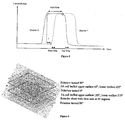
- Figure 2 shows a typical transmission function for an ideal individual slit.
- the slit opens at t 1 and closes at t 2 .
- the time to switch between two states should ideally be infinitely fast, but in practice is a finite time. This time is known as the rise-time and fall-time, and will set the maximum speed at which the shutter can be run. Since the slit is not blocking light properly during transition there will be some light leakage, which gives rise to faint unwanted images known as ghost images. In addition a loss of overall image contrast can be expected due to this transition leakage. Another factor that reduces contrast is the fact that LCD cells never manage to block light one hundred percent efficiently, even in a stable dark state.
- DFLC Dual-frequency Liquid Crystal
- a problem with current shutter technology is that LCDs cannot reliably switch at the high rates required for a flicker free autostereoscopic display apparatus.
- An LCD apparatus is typically arranged to switch between two states of polarization. Usually, degrees of polarization between the two states of polarization may also be selected with the LCD apparatus.
- the time to switch between two states is finite.
- the time for a transition from a first state to a second state is known as the rise-time and the reverse transition is known as the fall-time.
- the fall-time is typically a relaxation time and this is the strongest factor determining the maximum speed at which the shutter can switch. Since the slit does not block light properly during transition there is light leakage. Light leakage may give rise to faint unwanted images known as ghost images. In addition, a loss of overall image contrast can be expected due to this transition leakage. Another factor that reduces contrast is the fact that LCD cells do not exhibit zero percent transmission, even in a stable dark state.
- a shutter with high contrast fast rise time and fast fall-time but using a standard liquid crystal material that switches quickly in only one direction may be obtained by using a double cell solution.
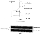
- Such a shutter can be built up from two individual liquid crystal cells, one with a fast dark to clear transition and one with a fast clear to dark transition as shown in Figure 3 .
- the top normally white cell is clear (commonly termed “white”) in the art when no electric field is present.
- the normally black cell is opaque (commonly termed “black” in the art) when no field is applied.
- a third polariser can be placed between the two cells which acts as a clean up filter to ensure that the light is correctly polarised when entering the next liquid crystal cell.
- polarisers and liquid crystal material there are numerous configurations of polarisers and liquid crystal material to achieve the same double cell effect with both fast rise time and fast fall-time, however only one example will be given. Assuming light enters the top of double cell shown in and assuming each cell is made up of a planar aligned (PA) liquid crystal material then one possible configuration is:
- the middle polariser ensures correct polarisation state of the light entering the second cell. This may be particularly useful during the transition of the first cell when the polarisation state is unknown.
- Some liquid crystals have an associated hold time when switching, which can set a minimum limit to the length of the pulse.
- normally black (or opaque) cell One challenge associated with the above configuration is the normally black (or opaque) cell.
- normally black cell For the normally black cell to achieve high contrast it must act as a perfect half wave-plate which is difficult to achieve for planar aligned liquid crystals. Therefore this cell will often have considerably lower contrast than the normally white cell.
- a first requirement of the retardation film is that it has the correct retardation for one wavelength in the most sensitive part of the optical spectrum, around 554 nm. For optimum transmission, it should have a retardation value around 277 nm. However, the retardation value should also be matched to the liquid crystal cell, and a somewhat smaller value means a thinner cell with faster response, sacrificing the transmission to a small degree.
- a second requirement of the retardation film is that the retardation should have the similar wavelength dependence to the liquid crystal used.
- a third requirement of the retardation film is that it gives a good angular dependence together with the liquid crystal panel. This can be achieved by using a material with negative birefringence. If the retardation film is not explicitly designed to provide good angular properties, these may be improved by suitable orientation of the liquid crystal and the retardation film. For example, a panel with the rubbing, polariser and retardation film rotated 45 degrees, could reduce the angular dependence in the horizontal direction.
- Figure 6 shows how a double cell can be made using a retardation film.
- a retardation film according to embodiments may satisfy any combination of the above requirements.
- Figure 6 shows a six layer double cell using a retardation film.
- the first layer is a polarizer arranged at 90[deg.] to an alignment axis.
- the second layer is a Planar Alignment (PA) cell comprising liquid crystal arranged between an upper surface and a lower surface. The upper surface rubbed at 45[deg.] to the alignment axis. The lower surface buffed at 225[deg.] to the alignment axis.
- the third layer is a polarizer arranged parallel to the alignment axis.
- the fourth layer is a Planar Alignment (PA) cell having an upper surface buffed at 135[deg.] to the alignment axis and a lower surface buffed at 315[deg.] to the alignment axis.
- the fifth layer is a retarder sheet with its slow axis arranged at 45[deg.] to the alignment axis.
- the sixth layer is a polarizer arranged at 90[deg.] to the
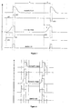
- the contrast ratio is different for the normally white and the normally black cell, with the normally black typically having poorer contrast.
- the overall contrast may be improved by maximising the time during which the cell with the higher contrast is in the black state.
- the normally black cell only needs to block light during period (c). If the fall time (a) of the normally white can be reduced then the overall contrast can be improved.
- the goal is to allow the normally white cell to block light as long as possible and let the normally black cell only when the normally white is transitioning, i.e. make period (b) as long as possible and (c), i.e. (a), as short as possible.
- the cell could be optimised by having different response curves for the two cells.
- the normally black cell could be thicker to give good contrast with a longer fall time, and the normally white cell could be thinner to give a shorter fall time.
- Figure 8 shows transmission against time for a normally white cell, a normally black cell, and a double cell comprising a normally black cell and a normally white cell.
- Figure 8 also shows drive signals (voltage against time) for the normally black cell and the normally white cell.
- ECS Electrically Commanded Surfaces
- the response time may vary along the slits or other geometry being switched. The variation will depend on the resistivity per unit length of the strip and the capacity per unit length.
- One way to reduce the variation is to use a low resistance conductive layer.
- Another way is to connect both ends of the slits to the driver electronics.
- Yet another way is to add a metal wire along the slit to reduce resistance.
- Another solution is to compensate for the variation in response time by modifying the input image that is synchronised with the shutter.
- One option is to drive the panels with an AC waveform as shown in Figure 9 .
- an electric field will switch the cell. Note that the polarity switches within one cycle thus providing a zero dc bias within the "closed" cycle.
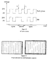
- Another way to reduce the capacitive load is to drive each individual slit with alternating dc drive signals. This would mean that the backplane is constantly at ground and that each slit receives alternating fields, e.g. +25V and-25V. This ensures the zero dc bias condition and requires that only a strip is driven. Thus the entire backplane drive can be removed.
- the signal to one slit would be as shown in Figure 11 .
- the maximum viewing angle is up to 180 degrees and only limited by the thickness of the cell and the maximum viewing angle for the liquid crystal. Having two or more shutters will change the maximum viewing angle as shown in the Figure 12 . Furthermore, the effective slit width will gradually become smaller when increasing the angle away from the normal going out from the center of the slit. This will make the brightness dependent on viewing angle and can introduce black stripes.
- Figure 13 shows the effect on viewing angle of adding an extra shutter. It has been drawn with the Shutter B, with the wider slit, between Shutter A and the display. However, a similar analysis would be applicable if it was further away from the display by a distance s. In some instances the viewing angle should not be reduced compared to having only one shutter. To achieve this one can ensure that the system is designed for viewing angles no greater than ⁇ .
- l b will be made up of several elements of width 1'. Due to symmetry, 1' will in many instances be a multiple of l a (because the slit for Shutter B will need to move along with the slit for Shutter A), which limits the range of values that r can take. Effectively the resolution of Shutter B determines at what steps ⁇ can be changed dynamically.
- Another way to change the viewing angle dynamically is to change the distance between the two shutters.
- the mechanism for changing the distance can be combined with a device that accurately measures the distances s and d. This would allow other system parameters that are affected by these distances to be adjusted dynamically.
- the minimum distance between the two shutters is limited by glass substrate thickness.
- a typical glass substrate is 1.1 mm thick, although thinner substrates exist.
- the liquid crystal layer will be a few microns and can be ignored.
- the thickness s will be 2.2 mm and for a single 1.1 mm.
- Two cases are considered, one with an 80 slit shutter and one with a 256 slit shutter. Both are assumed to be 400mm wide, giving slit widths l a of 5mm and 1.56mm respectively.
- FIG 16 A weaker case is shown in Figure 16 .
- the problem can be described as a number of shutter states in a repeated time sequence.
- the number of shutter states equals the spacing between the simultaneously open slits (N).
- the number of states in the time sequence is usually the same, i.e. N.
- One way to improve the visual appearance of the sequence is to reduce the negative effect of the fall time t f . This can be done by finding sequences based on constraint programming techniques. The following set of constraints is an example that would give an effective sequence:
- N is large, r is small and the fall time short it will be easier to find an optimal sequence. In that respect, using materials with short fall time and putting the shutters close together will simplify the design.
- f 1 the cost depending on separation in distance between shutter states and f 2 gives the relative cost depending on the separation in time.
- f 1 (j) the cost for the jth adjacent slit opening at 1th same time
- Shutter A could be a normally white cell with higher contrast since it will be in the black state for a larger proportion of the cycle. In other instances one may choose to have a normally white cell with faster fall time and use that as Shutter B.
- N the number of steps between slits on Shutter A that are open at the same point in time must at least be 2r+1 if crosstalk between viewing regions is to be avoided. It should be noted though that in some cases this repeated viewing zone is desired.
- r does not have to be constant and the slit on Shutter B does not need to be centered with the slit of Shutter A.
- the frustums may be shifted outwards as shown in Figure 17 .
- the dotted line indicates a symmetric frustum where the slit on Shutter B would be centered with the slit for Shutter A if they are defined as the intersection of the shutters and the frustum.
- the full line indicates a frustum that is shifted outwards and is non-symmetric in the sense that the slits for Shutter B are not centered with the slits for Shutter A if they are defined as the intersection of the shutters and the frustum.
- An example of a double shutter LCD intended for horizontal parallax only 3D display, i.e. where a viewer will see different images only for different horizontal viewing positions, will typically consist of columns rather than pixels which is typically for conventional 2D LCD screens.
- the shutter LCD screen will consist of many columns typically 1-5mm wide that can switch between optically transparent and optically opaque.
- such an LCD screen can be achieved by using two panels: One that switches quickly from opaque to transparent (normally black) and one that switches quickly from transparent to opaque (normally white).
- a cell gap of around 2.5 micrometers is used.
- One suitable liquid crystal material for use in both cells is MLC14300-100.
- the normally black and normally white cells are configured as described above with reference to the Double cell shutter overview, with the normally white using crossed polarisers and material director at 45° to input polarizer, which is achieved by rubbing the alignment material (for example PI 7992) at 45° with respect to polariser orientation.
- the normally black cell has the polarisers in parallel and with material director also aligned at 45° to input polariser as described above with reference to the Double cell shutter overview. Due to the narrow cell gap of the normally black cell a compensation film might improve contrast. In such case the compensation film is incorporated as shown in Figure 6 . Alternatively a third cell, an exact replica of the normally black is included as a compensation film.
- a high voltage is required. Typically around 25 volts will suffice to switch the panels in approximately 40 micro seconds. However, if a larger cell gap is required then a higher voltage will be required.
- the shutter can also be used to vary the viewing zones dynamically, from narrow to wide cones.
- One way to do this is to change the width of the slits being switched by varying the number of adjacent slits being switched simultaneously.
- the image on the display that is synchronized with the shutter should be rendered to match the slit width to maintain a correct image.
- Another way to change the viewing zones is to have a mechanism to change the distance between the shutter and the display. Again the image on the display should be rendered to match the distance between the shutter and the display.
Landscapes
- Engineering & Computer Science (AREA)
- Multimedia (AREA)
- Signal Processing (AREA)
- Physics & Mathematics (AREA)
- General Physics & Mathematics (AREA)
- Optics & Photonics (AREA)
- Testing, Inspecting, Measuring Of Stereoscopic Televisions And Televisions (AREA)
- Control Of Indicators Other Than Cathode Ray Tubes (AREA)
- Liquid Crystal (AREA)
- Devices For Indicating Variable Information By Combining Individual Elements (AREA)
- Controls And Circuits For Display Device (AREA)
Claims (12)
- Verschluss (Shutter) für ein autostereoskopisches Display, mit:einem ersten umschaltbaren Blenden-Array, das eine Vielzahl umschaltbarer Blendenelemente hat und einen Teil einer ersten umschaltbaren Parallaxenbarriere bildet, wobei jedes umschaltbare Blendenelement des ersten umschaltbaren Blenden-Arrays eine schnellere Umschaltzeit von einem im Wesentlichen transparenten Zustand, in dem das umschaltbare Blendenelement eine entsprechende Blende bildet, in einen im Wesentlichen undurchsichtigen Zustand hat, als seine langsamere Umschaltzeit von einem im Wesentlichen undurchsichtigen Zustand in einen im Wesentlichen transparenten Zustand; undeinem zweiten umschaltbaren Blenden-Array, das eine Vielzahl umschaltbarer Blendenelemente hat und einen Teil einer zweiten umschaltbaren Parallaxenbarriere bildet, wobei jedes umschaltbare Blendenelement des zweiten umschaltbaren Blenden-Arrays eine schnellere Umschaltzeit von einem im Wesentlichen undurchsichtigen Zustand in einen im Wesentlichen transparenten Zustand hat, in dem das umschaltbare Blendenelement eine entsprechende Blende bildet, als seine langsamere Umschaltzeit von einem im Wesentlichen transparenten Zustand in einen im Wesentlichen undurchsichtigen Zustand;wobei die umschaltbaren Blendenelemente des ersten umschaltbaren Blenden-Arrays sich wenigstens teilweise mit jeweiligen umschaltbaren Blendenelementen des zweiten umschaltbaren Blenden-Arrays überlappen; undAntriebsmitteln, die im Gebrauch dazu ausgelegt sind, den ersten und den zweiten umschaltbaren Blenden-Array zu treiben, wobei für jede Blende, die in einem des ersten und des zweiten umschaltbaren Blenden-Arrays ausgebildet ist, wobei die Blende eine erste Blende ist und durch Öffnen eines oder mehrerer der umschaltbaren Blendenelemente des einen des ersten und des zweiten umschaltbaren Blenden-Arrays ausgebildet wird, und wobei die erste Blende eine erste Breite hat:eine Anzahl umschaltbarer Blendenelemente in dem anderen des ersten und des zweiten umschaltbaren Blenden-Arrays geöffnet werden, um dadurch eine entsprechende zweite Blende in dem anderen des ersten und des zweiten umschaltbaren Blenden-Arrays auszubilden, wobei die zweite Blende die erste Blende vollständig überlappt und eine zweite Breite hat, die größer als die erste Breite ist;wobei eines des ersten und des zweiten umschaltbaren Blenden-Arrays ein höheres Kontrastverhältnis hat, als das andere des ersten und des zweiten umschaltbaren Blenden-Arrays; undwobei die langsamere Umschaltzeit der umschaltbaren Blendenelemente des umschaltbaren Blenden-Arrays mit dem höheren Kontrastverhältnis geringer ist, als die langsamere Umschaltzeit des anderen umschaltbaren Blenden-Arrays.
- Verschluss nach Anspruch 1, wobei die in den umschaltbaren Blenden-Arrays ausgebildeten Blenden Säulen aufweisen, und wobei die Säulen des ersten und des zweiten umschaltbaren Blenden-Arrays ausgerichtet sind.
- Verschluss nach einem der vorhergehenden Ansprüche, wobei das erste und das zweite umschaltbare Blenden-Array so angeordnet sind, dass eine Linie durch die Mitte sowohl einer in dem ersten umschaltbaren Blenden-Array ausgebildeten Blende als auch einer in dem zweiten umschaltbaren Blenden-Array ausgebildeten Blende senkrecht zu der Oberfläche beider Blenden steht.
- Verschluss nach Anspruch 1, wobei die in den umschaltbaren Blenden-Arrays ausgebildeten Blenden Säulen aufweisen, und wobei die Säulen des ersten und des zweiten umschaltbaren Blenden-Arrays zueinander versetzt sind.
- Autostereoskopisches Display, das ein zweidimensionales Display und einen Verschluss nach einem der vorhergehenden Ansprüche aufweist.
- Autostereoskopisches Display nach Anspruch 5, wobei
das erste umschaltbare Blenden-Array zwischen dem zweiten umschaltbaren Blenden-Array und dem zweidimensionalen Display angeordnet ist; oder
das zweite umschaltbare Blenden-Array zwischen dem ersten umschaltbaren Blenden-Array und dem zweidimensionalen Display angeordnet ist. - Autostereoskopisches Display nach Anspruch 5 oder 6, wobei das zweidimensionale Display ein Bildschirm eines Projektors ist, wobei der Projektor optional ein DMD aufweist.
- Verfahren zum Betreiben des Verschlusses nach einem der vorhergehenden Ansprüche, wobei das Verfahren umfasst:Anordnen einer Anzahl der umschaltbaren Blendenelemente des ersten umschaltbaren Blenden-Arrays derart, dass sie in dem im Wesentlichen transparenten Zustand sind;Anordnen einer Anzahl der umschaltbaren Blendenelemente des zweiten umschaltbaren Blenden-Arrays derart, dass sie in dem im Wesentlichen undurchsichtigen Zustand sind;Umschalten der Anzahl der umschaltbaren Blendenelemente des zweiten umschaltbaren Blenden-Arrays von dem im Wesentlichen undurchsichtigen Zustand in den im Wesentlichen transparenten Zustand, wodurch ein erster Abschnitt des Verschlusses im Wesentlichen transparent wird.
- Verfahren zum Betreiben des Verschlusses nach einem der vorhergehenden Ansprüche, wobei das Verfahren umfasst:Anordnen einer Anzahl der umschaltbaren Blendenelemente des ersten umschaltbaren Blenden-Arrays derart, dass sie in dem im Wesentlichen transparenten Zustand sind;Anordnen einer Anzahl der umschaltbaren Blendenelemente des zweiten umschaltbaren Blenden-Arrays derart, dass sie in dem im Wesentlichen transparenten Zustand sind;Umschalten der Anzahl der umschaltbaren Blendenelemente des zweiten umschaltbaren Blenden-Arrays von dem im Wesentlichen transparenten Zustand in den im Wesentlichen undurchsichtigen Zustand, wodurch ein zweiter Abschnitt des Verschlusses im Wesentlichen undurchsichtig wird.
- Verfahren nach Anspruch 8 oder 9, wobei die umschaltbaren Blendenelemente des ersten umschaltbaren Blenden-Arrays eine erste Abfallzeit zum Umschalten von dem im Wesentlichen undurchsichtigen Zustand in den im Wesentlichen transparenten Zustand haben, und wobei die umschaltbaren Blendenelemente des zweiten umschaltbaren Blenden-Arrays eine zweite Abfallzeit zum Umschalten von dem im Wesentlichen transparenten Zustand in den im Wesentlichen undurchsichtigen Zustand haben.
- Verfahren nach einem der Ansprüche 8 bis 10, wobei ein Umschaltschema, das für die umschaltbaren Blenden-Arrays verwendet wird, bestimmt wird durch eines von:Minimieren einer Kostenfunktion, die mit geradlinigem Ghosting und Ghosting im Winkel in Zusammenhang steht, wobei die Kostenfunktion den Betrag von geradlinigem Ghosting und Ghosting im Winkel definiert, der in einem durch den Verschluss betrachteten Bild wahrgenommen wird;Minimieren einer Kostenfunktion, die mit Striping in Zusammenhang steht, wobei die Kostenfunktion den Betrag von Striping definiert, der in einem durch den Verschluss betrachteten Bild wahrgenommen wird;Minimieren einer Kostenfunktion, die mit geradlinigem Ghosting, Ghosting im Winkel und Striping in Zusammenhang steht, wobei die Kostenfunktion den Betrag von geradlinigem Ghosting, Ghosting im Winkel und Striping definiert, der in einem durch den Verschluss betrachteten Bild wahrgenommen wird.
- Verfahren nach Anspruch 11, wobei das Umschaltschema definiert, wann jedes umschaltbare Blendenelement geöffnet wird, und wann jedes umschaltbare Blendenelement geschlossen wird.
Applications Claiming Priority (3)
| Application Number | Priority Date | Filing Date | Title |
|---|---|---|---|
| GB0607727A GB0607727D0 (en) | 2006-04-19 | 2006-04-19 | Bandwidth improvement for 3D display |
| GB0607726A GB0607726D0 (en) | 2006-04-19 | 2006-04-19 | High speed display shutter |
| PCT/GB2007/001407 WO2007119064A1 (en) | 2006-04-19 | 2007-04-19 | High speed display shutter for autostereoscopic display |
Publications (2)
| Publication Number | Publication Date |
|---|---|
| EP2014102A1 EP2014102A1 (de) | 2009-01-14 |
| EP2014102B1 true EP2014102B1 (de) | 2016-03-09 |
Family
ID=38217306
Family Applications (3)
| Application Number | Title | Priority Date | Filing Date |
|---|---|---|---|
| EP07732449.9A Active EP2014102B1 (de) | 2006-04-19 | 2007-04-19 | Schnelle anzeigeblende für eine autostereoskopische anzeige |
| EP11194100.1A Ceased EP2477409A3 (de) | 2006-04-19 | 2007-04-19 | Autostereoskopischen Anzeige mit einstellbaren Anzeigeparametern |
| EP07732448.1A Active EP2014101B1 (de) | 2006-04-19 | 2007-04-19 | Bandbreitenverbesserung für eine 3d-anzeige |
Family Applications After (2)
| Application Number | Title | Priority Date | Filing Date |
|---|---|---|---|
| EP11194100.1A Ceased EP2477409A3 (de) | 2006-04-19 | 2007-04-19 | Autostereoskopischen Anzeige mit einstellbaren Anzeigeparametern |
| EP07732448.1A Active EP2014101B1 (de) | 2006-04-19 | 2007-04-19 | Bandbreitenverbesserung für eine 3d-anzeige |
Country Status (9)
| Country | Link |
|---|---|
| US (3) | US9497445B2 (de) |
| EP (3) | EP2014102B1 (de) |
| JP (2) | JP5154543B2 (de) |
| KR (3) | KR101041635B1 (de) |
| CN (2) | CN102123292B (de) |
| AU (2) | AU2007238391B2 (de) |
| CA (2) | CA2649415C (de) |
| NO (2) | NO342535B1 (de) |
| WO (2) | WO2007119063A1 (de) |
Families Citing this family (46)
| Publication number | Priority date | Publication date | Assignee | Title |
|---|---|---|---|---|
| GB0410551D0 (en) * | 2004-05-12 | 2004-06-16 | Ller Christian M | 3d autostereoscopic display |
| CN102123292B (zh) * | 2006-04-19 | 2014-06-25 | 塞特雷德股份公司 | 3d显示器的带宽改善 |
| GB0716776D0 (en) * | 2007-08-29 | 2007-10-10 | Setred As | Rendering improvement for 3D display |
| KR101451565B1 (ko) * | 2008-02-13 | 2014-10-16 | 삼성전자 주식회사 | 비안경식 입체영상 디스플레이 시스템 |
| KR101626063B1 (ko) * | 2010-01-21 | 2016-06-01 | 삼성디스플레이 주식회사 | 입체 영상 표시 방법 및 이를 수행하기 위한 표시 장치 |
| TWI423192B (zh) * | 2010-06-22 | 2014-01-11 | Wistron Corp | 多工顯示系統和其顯示方法 |
| TWI408948B (zh) * | 2010-08-16 | 2013-09-11 | Wistron Corp | 根據不同視角播放相對應之立體影像之方法及其相關影像處理系統 |
| EP2431786A1 (de) * | 2010-09-17 | 2012-03-21 | Bayer MaterialScience AG | Autostereoskopisches 3D-Display |
| KR101082056B1 (ko) * | 2010-09-29 | 2011-11-10 | 주식회사 엘지화학 | 입체 영상 표시 장치 |
| GB201019694D0 (en) * | 2010-11-19 | 2011-01-05 | Setred As | Camera and visualisation of images and video for autostereoscopic display |
| US8698880B2 (en) * | 2010-12-01 | 2014-04-15 | Industrial Technology Research Institute | System and method for time multiplexed stereo display and display apparatus |
| US20120194755A1 (en) * | 2011-01-27 | 2012-08-02 | Reald Inc. | Ultrafast twisted nematic liquid crystal display |
| CN103718094B (zh) * | 2011-03-30 | 2016-04-27 | 拉谢扎·科米托夫 | 快速切换的双盒液晶装置 |
| CA2842572C (en) | 2011-08-16 | 2020-10-13 | Imax Corporation | Hybrid image decomposition and projection |
| EP2769261B1 (de) | 2011-10-20 | 2022-07-06 | IMAX Corporation | Verzerrungskompensation für bildprojektion |
| CA2847999C (en) | 2011-10-20 | 2019-11-12 | Imax Corporation | Invisible or low perceptibility of image alignment in dual projection systems |
| KR101901858B1 (ko) * | 2011-12-01 | 2018-10-01 | 삼성디스플레이 주식회사 | 표시장치 |
| KR101477967B1 (ko) | 2012-03-12 | 2014-12-31 | 삼성디스플레이 주식회사 | 표시 패널의 구동 방법 및 이를 수행하기 위한 표시 장치 |
| KR102039947B1 (ko) * | 2012-05-18 | 2019-11-05 | 리얼디 스파크, 엘엘씨 | 지향성 광원을 위한 제어 시스템 |
| US9265458B2 (en) | 2012-12-04 | 2016-02-23 | Sync-Think, Inc. | Application of smooth pursuit cognitive testing paradigms to clinical drug development |
| CN103152594B (zh) * | 2013-02-20 | 2015-04-01 | 京东方科技集团股份有限公司 | 一种3d显示控制方法及装置 |
| US9380976B2 (en) | 2013-03-11 | 2016-07-05 | Sync-Think, Inc. | Optical neuroinformatics |
| US9967546B2 (en) | 2013-10-29 | 2018-05-08 | Vefxi Corporation | Method and apparatus for converting 2D-images and videos to 3D for consumer, commercial and professional applications |
| US20150116458A1 (en) | 2013-10-30 | 2015-04-30 | Barkatech Consulting, LLC | Method and apparatus for generating enhanced 3d-effects for real-time and offline appplications |
| CA2931776C (en) | 2013-11-27 | 2025-06-17 | Magic Leap, Inc. | VIRTUAL REALITY AND AUGMENTED REALITY SYSTEMS AND PROCESSES |
| US9746739B2 (en) | 2014-06-05 | 2017-08-29 | Microsoft Technology Licensing, Llc | See-through dimming panel |
| US10158847B2 (en) | 2014-06-19 | 2018-12-18 | Vefxi Corporation | Real—time stereo 3D and autostereoscopic 3D video and image editing |
| TWI537671B (zh) | 2014-08-14 | 2016-06-11 | 台達電子工業股份有限公司 | 環繞光場顯示器及其操作方法 |
| TWI537605B (zh) | 2014-08-28 | 2016-06-11 | 台達電子工業股份有限公司 | 立體顯示裝置與應用其之立體顯示方法 |
| CN104240670B (zh) * | 2014-10-10 | 2016-04-06 | 天津三星电子有限公司 | 一种显示参数调整的方法及显示器 |
| CN107211119B (zh) * | 2015-01-30 | 2019-03-01 | 三菱电机株式会社 | 图像处理装置、图像显示装置及图像处理方法 |
| CN105093548B (zh) * | 2015-08-20 | 2018-10-23 | 京东方科技集团股份有限公司 | 3d显示装置的控制方法、控制装置及3d显示装置 |
| US10652526B2 (en) * | 2016-04-25 | 2020-05-12 | Sun Yat-Sen University | Three-dimentional display system based on division multiplexing of viewer's entrance-pupil and display method thereof |
| CN106488155A (zh) * | 2016-10-17 | 2017-03-08 | 青岛海信电器股份有限公司 | 一种屏幕菜单信号的生成方法及装置 |
| CA2953752A1 (en) * | 2017-01-06 | 2018-07-06 | Libra At Home Ltd | Virtual reality apparatus and methods therefor |
| US11601638B2 (en) * | 2017-01-10 | 2023-03-07 | Intel Corporation | Head-mounted display device |
| CN107340602A (zh) * | 2017-06-09 | 2017-11-10 | 利亚德光电股份有限公司 | 3d显示装置和方法 |
| JP7015520B2 (ja) * | 2017-11-01 | 2022-02-15 | 国立大学法人電気通信大学 | 広視野角空中映像表示装置 |
| CN109298538B (zh) * | 2018-11-20 | 2024-03-26 | 成都航空职业技术学院 | 均匀光学效率的双视3d显示装置 |
| CN109254412B (zh) * | 2018-11-20 | 2024-03-22 | 成都航空职业技术学院 | 基于矩形针孔阵列的双视3d显示装置 |
| CN112114437B (zh) * | 2019-06-03 | 2022-06-07 | 驻景(广州)科技有限公司 | 一种实现大视区小视点间距的三维显示方法 |
| DE102019213764A1 (de) * | 2019-09-10 | 2021-03-11 | Continental Automotive Gmbh | Stereoskopisches Display und Verfahren zum Betreiben eines stereoskopischen Displays |
| US11330249B1 (en) * | 2020-12-01 | 2022-05-10 | Sun Yat-Sen University | Three-dimensional display method for large field of view and small viewing-zone interval |
| CN114895479B (zh) * | 2022-05-18 | 2024-05-10 | 成都工业学院 | 宽视角双视3d显示装置 |
| CN114791678B (zh) * | 2022-05-18 | 2024-05-14 | 成都工业学院 | 基于双渐变孔径狭缝光栅的双视3d显示装置 |
| CN114895481B (zh) * | 2022-05-18 | 2024-05-10 | 成都工业学院 | 基于狭缝光栅和偏振光栅的双视3d显示装置 |
Citations (4)
| Publication number | Priority date | Publication date | Assignee | Title |
|---|---|---|---|---|
| JPS58199321A (ja) * | 1982-05-17 | 1983-11-19 | Seiko Instr & Electronics Ltd | 高速液晶シヤツタ− |
| DE19836886A1 (de) * | 1998-08-14 | 2000-03-02 | Dieter Just | Verfahren zur autostereoskopischen Bild-, Film- und Fernsehaufnahme- und -wiedergabe durch Multi-Apertur-Multiplexing |
| US6674463B1 (en) * | 1999-08-06 | 2004-01-06 | Deiter Just | Technique for autostereoscopic image, film and television acquisition and display by multi-aperture multiplexing |
| WO2005112474A2 (en) * | 2004-05-12 | 2005-11-24 | Setred Ab | 3d display method and apparatus |
Family Cites Families (71)
| Publication number | Priority date | Publication date | Assignee | Title |
|---|---|---|---|---|
| GB248344A (en) | 1925-02-27 | 1927-03-10 | Siemens Schuckertwerke Gmbh | Improvements in or relating to tension regulating by means of asynchronous wattless current machines |
| US4740073A (en) * | 1982-12-27 | 1988-04-26 | Meacham G B Kirby | System for projecting three-dimensional images |
| JPS62153833A (ja) * | 1985-12-26 | 1987-07-08 | Sharp Corp | 液晶光シヤツタ−の駆動方式 |
| US4853769A (en) | 1987-06-16 | 1989-08-01 | Massachusetts Institute Of Technology | Time multiplexed auto-stereoscopic three-dimensional imaging system |
| GB8716369D0 (en) * | 1987-07-10 | 1987-08-19 | Travis A R L | Three-dimensional display device |
| JP2857429B2 (ja) | 1989-10-02 | 1999-02-17 | 日本放送協会 | 3次元画像表示装置および方法 |
| KR0123909B1 (en) | 1991-11-05 | 1997-11-26 | Sharp Kk | A three-dimensional display system |
| EP0664917B1 (de) | 1992-10-15 | 2004-03-03 | Texas Instruments Incorporated | Anzeigevorrichtung |
| GB2272555A (en) * | 1992-11-11 | 1994-05-18 | Sharp Kk | Stereoscopic display using a light modulator |
| GB2278223A (en) | 1993-05-21 | 1994-11-23 | Sharp Kk | Spatial light modulator and directional display |
| JP3268586B2 (ja) * | 1993-09-24 | 2002-03-25 | 富士通株式会社 | 立体映像の表示装置と撮影記録装置 |
| US5448322A (en) | 1993-11-05 | 1995-09-05 | Vision Iii Imaging, Inc. | Autostereoscopic imaging apparatus and method using a parallax scanning lens aperture |
| EP0656555B1 (de) | 1993-12-01 | 2003-03-19 | Sharp Kabushiki Kaisha | Display für dreidimensionale Bilder |
| JPH0915532A (ja) | 1995-06-29 | 1997-01-17 | Canon Inc | 立体画像表示方法及びそれを用いた立体画像表示装置 |
| JP2778543B2 (ja) * | 1995-07-27 | 1998-07-23 | 日本電気株式会社 | 立体表示装置 |
| JP2966781B2 (ja) * | 1995-11-16 | 1999-10-25 | 三洋電機株式会社 | 立体画像表示装置の制御方法 |
| JPH09171156A (ja) | 1995-12-20 | 1997-06-30 | Fujitsu General Ltd | 立体画像表示装置 |
| JPH09289655A (ja) | 1996-04-22 | 1997-11-04 | Fujitsu Ltd | 立体画像表示方法及び多視画像入力方法及び多視画像処理方法及び立体画像表示装置及び多視画像入力装置及び多視画像処理装置 |
| GB2320156A (en) | 1996-12-07 | 1998-06-10 | Sharp Kk | Directional display and method of making a mask for a directional display |
| GB2317291A (en) * | 1996-09-12 | 1998-03-18 | Sharp Kk | Observer tracking directional display |
| GB2321815A (en) | 1997-02-04 | 1998-08-05 | Sharp Kk | Autostereoscopic display with viewer position indicator |
| US6366281B1 (en) * | 1996-12-06 | 2002-04-02 | Stereographics Corporation | Synthetic panoramagram |
| WO1998043441A1 (en) | 1997-03-27 | 1998-10-01 | Litton Systems, Inc. | Autostereoscopic projection system |
| JP3500036B2 (ja) * | 1997-05-15 | 2004-02-23 | 三洋電機株式会社 | プラズマディスプレイパネルを用いた時分割メガネ方式の立体映像表示方法 |
| GB9713658D0 (en) | 1997-06-28 | 1997-09-03 | Travis Adrian R L | View-sequential holographic display |
| KR100304784B1 (ko) * | 1998-05-25 | 2001-09-24 | 박호군 | 편광과광띠를이용한다자시청용3차원영상표시장치 |
| JP2000004451A (ja) * | 1998-06-15 | 2000-01-07 | Idemitsu Kosan Co Ltd | 立体画像表示方法および装置 |
| JP2000092520A (ja) * | 1998-09-16 | 2000-03-31 | Toshiba Corp | 立体映像表示装置 |
| US6795241B1 (en) * | 1998-12-10 | 2004-09-21 | Zebra Imaging, Inc. | Dynamic scalable full-parallax three-dimensional electronic display |
| GB9907277D0 (en) * | 1999-03-31 | 1999-05-26 | Cambridge 3D Display Ltd | Wide field view projection display |
| US20020063807A1 (en) * | 1999-04-19 | 2002-05-30 | Neal Margulis | Method for Performing Image Transforms in a Digital Display System |
| US6128132A (en) * | 1999-07-13 | 2000-10-03 | Disney Enterprises, Inc. | Method and apparatus for generating an autostereo image |
| GB2354389A (en) | 1999-09-15 | 2001-03-21 | Sharp Kk | Stereo images with comfortable perceived depth |
| EP1087627A3 (de) * | 1999-09-24 | 2004-02-18 | SANYO ELECTRIC Co., Ltd. | Autostereoskopische Bildanzeigevorrichtung |
| US6717728B2 (en) * | 1999-12-08 | 2004-04-06 | Neurok Llc | System and method for visualization of stereo and multi aspect images |
| US7046271B2 (en) | 2000-01-25 | 2006-05-16 | X3D Technologies Gmbh | Method and system for the three-dimensional representation |
| US7254265B2 (en) * | 2000-04-01 | 2007-08-07 | Newsight Corporation | Methods and systems for 2D/3D image conversion and optimization |
| GB0010685D0 (en) | 2000-05-03 | 2000-06-28 | Koninkl Philips Electronics Nv | Autostereoscopic display driver |
| TW540228B (en) | 2000-11-03 | 2003-07-01 | Actuality Systems Inc | Three-dimensional display systems |
| US20040070556A1 (en) * | 2001-02-22 | 2004-04-15 | Sebastien Weitbruch | Stereoscopic plasma display and interleaving of fields |
| EP1415482A1 (de) * | 2001-07-27 | 2004-05-06 | Koninklijke Philips Electronics N.V. | Autostereoskopische bildanzeigevorrichtung mit benutzernachfolgesystem |
| AU2002343480A1 (en) * | 2001-10-05 | 2003-04-22 | Teraburst Networks, Inc. | Immersive visualization theater system and method |
| US7043073B1 (en) * | 2001-10-19 | 2006-05-09 | Zebra Imaging, Inc. | Distortion correcting rendering techniques for autostereoscopic displays |
| WO2003048840A1 (es) * | 2001-12-07 | 2003-06-12 | Juan Dominguez-Montes | Doble barrera de paralaje activa para la vision de imagenes estereoscopicas |
| AU2002361857A1 (en) | 2001-12-19 | 2003-07-09 | Actuality Systems, Inc. | A radiation conditioning system |
| KR20050016344A (ko) | 2002-04-17 | 2005-02-21 | 필립 안소니 셔만 | 자동 입체 디스플레이 |
| GB2387664B (en) | 2002-04-17 | 2005-08-24 | Philip Anthony Surman | Autostereoscopic display |
| US6927886B2 (en) | 2002-08-02 | 2005-08-09 | Massachusetts Institute Of Technology | Reconfigurable image surface holograms |
| JP2004101826A (ja) * | 2002-09-09 | 2004-04-02 | Fuji Photo Optical Co Ltd | プロジェクタ用光学系およびこれを用いたプロジェクタ装置 |
| GB2393344A (en) | 2002-09-17 | 2004-03-24 | Sharp Kk | Autostereoscopic display |
| US6943790B2 (en) * | 2002-10-11 | 2005-09-13 | International Business Machines Corporation | Dual mesh resampling |
| GB2396070A (en) * | 2002-12-07 | 2004-06-09 | Sharp Kk | Multiple view display |
| JP2005010303A (ja) | 2003-06-17 | 2005-01-13 | Sea Phone Co Ltd | 表示装置 |
| GB2405043A (en) | 2003-08-13 | 2005-02-16 | Sharp Kk | Compensation for refraction effects in an autostereoscopic display |
| DE10339076B4 (de) * | 2003-08-26 | 2007-10-31 | Seereal Technologies Gmbh | Autostereoskopisches Multi-User-Display |
| GB2406731A (en) | 2003-08-30 | 2005-04-06 | Sharp Kk | Multiple view display having directional backlight |
| GB2405517A (en) | 2003-08-30 | 2005-03-02 | Sharp Kk | Multiple view display |
| GB2405542A (en) * | 2003-08-30 | 2005-03-02 | Sharp Kk | Multiple view directional display having display layer and parallax optic sandwiched between substrates. |
| GB2406730A (en) | 2003-09-30 | 2005-04-06 | Ocuity Ltd | Directional display. |
| US7372629B2 (en) * | 2003-11-06 | 2008-05-13 | Nec Corporation | Three-dimensional image display device, portable terminal device, display panel and fly eye lens |
| US7573491B2 (en) * | 2004-04-02 | 2009-08-11 | David Hartkop | Method for formatting images for angle-specific viewing in a scanning aperture display device |
| WO2005106572A1 (en) | 2004-04-02 | 2005-11-10 | David Hartkop | Scanning aperture three dimensional display device |
| US7375886B2 (en) | 2004-04-19 | 2008-05-20 | Stereographics Corporation | Method and apparatus for optimizing the viewing distance of a lenticular stereogram |
| JP4370215B2 (ja) * | 2004-07-29 | 2009-11-25 | オリンパス株式会社 | 投影表示装置 |
| JP4328311B2 (ja) | 2005-04-14 | 2009-09-09 | 株式会社東芝 | 三次元画像表示用多視点画像の作成方法およびプログラム |
| JP4687216B2 (ja) | 2005-04-18 | 2011-05-25 | ソニー株式会社 | 画像信号処理装置、カメラシステム、および画像信号処理方法 |
| GB2426351A (en) | 2005-05-19 | 2006-11-22 | Sharp Kk | A dual view display |
| GB2428344A (en) | 2005-07-08 | 2007-01-24 | Sharp Kk | Multiple view directional display |
| JP4488996B2 (ja) | 2005-09-29 | 2010-06-23 | 株式会社東芝 | 多視点画像作成装置、多視点画像作成方法および多視点画像作成プログラム |
| CN102123292B (zh) * | 2006-04-19 | 2014-06-25 | 塞特雷德股份公司 | 3d显示器的带宽改善 |
| GB0716776D0 (en) * | 2007-08-29 | 2007-10-10 | Setred As | Rendering improvement for 3D display |
-
2007
- 2007-04-19 CN CN201110081768.2A patent/CN102123292B/zh active Active
- 2007-04-19 AU AU2007238391A patent/AU2007238391B2/en active Active
- 2007-04-19 CA CA2649415A patent/CA2649415C/en active Active
- 2007-04-19 KR KR1020087027287A patent/KR101041635B1/ko active Active
- 2007-04-19 KR KR1020087027288A patent/KR100985215B1/ko active Active
- 2007-04-19 JP JP2009505951A patent/JP5154543B2/ja active Active
- 2007-04-19 WO PCT/GB2007/001406 patent/WO2007119063A1/en not_active Ceased
- 2007-04-19 KR KR1020117007981A patent/KR101124452B1/ko active Active
- 2007-04-19 EP EP07732449.9A patent/EP2014102B1/de active Active
- 2007-04-19 EP EP11194100.1A patent/EP2477409A3/de not_active Ceased
- 2007-04-19 US US12/297,590 patent/US9497445B2/en active Active
- 2007-04-19 JP JP2009505952A patent/JP5406014B2/ja active Active
- 2007-04-19 CA CA2649411A patent/CA2649411C/en active Active
- 2007-04-19 EP EP07732448.1A patent/EP2014101B1/de active Active
- 2007-04-19 CN CN201310413901.9A patent/CN103501432A/zh active Pending
- 2007-04-19 WO PCT/GB2007/001407 patent/WO2007119064A1/en not_active Ceased
- 2007-04-19 US US12/297,581 patent/US20090309887A1/en not_active Abandoned
- 2007-04-19 AU AU2007238392A patent/AU2007238392B9/en active Active
-
2008
- 2008-11-18 NO NO20084862A patent/NO342535B1/no unknown
- 2008-11-18 NO NO20084849A patent/NO342524B1/no unknown
-
2014
- 2014-05-30 US US14/291,299 patent/US9628782B2/en active Active
Patent Citations (4)
| Publication number | Priority date | Publication date | Assignee | Title |
|---|---|---|---|---|
| JPS58199321A (ja) * | 1982-05-17 | 1983-11-19 | Seiko Instr & Electronics Ltd | 高速液晶シヤツタ− |
| DE19836886A1 (de) * | 1998-08-14 | 2000-03-02 | Dieter Just | Verfahren zur autostereoskopischen Bild-, Film- und Fernsehaufnahme- und -wiedergabe durch Multi-Apertur-Multiplexing |
| US6674463B1 (en) * | 1999-08-06 | 2004-01-06 | Deiter Just | Technique for autostereoscopic image, film and television acquisition and display by multi-aperture multiplexing |
| WO2005112474A2 (en) * | 2004-05-12 | 2005-11-24 | Setred Ab | 3d display method and apparatus |
Also Published As
Similar Documents
| Publication | Publication Date | Title |
|---|---|---|
| EP2014102B1 (de) | Schnelle anzeigeblende für eine autostereoskopische anzeige | |
| JP4530267B2 (ja) | マルチプルビューディスプレイ | |
| US10048506B2 (en) | Stereoscopic 3D display device | |
| EP0833183B1 (de) | Räumlicher LCD Lichtmodulator als elektronische Parallaxen-Barriere | |
| US6943852B2 (en) | Single cell liquid crystal shutter glasses | |
| KR20070073036A (ko) | 고해상도의 필드 순차 오토스테레오스코픽 디스플레이 장치 | |
| JP2000004451A (ja) | 立体画像表示方法および装置 | |
| JP2000284224A (ja) | 立体画像表示システム | |
| GB2470623A (en) | Polarised 3D stereoscopic display to prevent crosstalk | |
| GB2405516A (en) | Multiple view display | |
| JPH10221646A (ja) | 立体画像表示装置 | |
| US20140009701A1 (en) | Method executed in liquid crystal device and liquid crystal glasses | |
| US20130201091A1 (en) | Three-dimensional display | |
| US8953106B2 (en) | Display unit, barrier device, and method of driving display unit | |
| JP3586681B2 (ja) | 反射形強誘電性液晶表示装置及びその駆動方法 | |
| US20130141653A1 (en) | Display apparatus | |
| CN101473662A (zh) | 用于自动立体显示器的高速显示器快门 | |
| HK1126604B (en) | High speed display shutter for autostereoscopic display | |
| Shestak et al. | Application of Pi-cells in time-multiplexed stereoscopic and autostereoscopic displays based on LCD panels | |
| JPH10232366A (ja) | 立体画像表示装置 | |
| KR101604134B1 (ko) | 액정셔터 안경과 이를 이용한 입체 영상표시장치 | |
| JP2000004454A (ja) | 立体表示装置 | |
| KR101829457B1 (ko) | 입체영상표시장치와 이의 구동방법 |
Legal Events
| Date | Code | Title | Description |
|---|---|---|---|
| PUAI | Public reference made under article 153(3) epc to a published international application that has entered the european phase |
Free format text: ORIGINAL CODE: 0009012 |
|
| 17P | Request for examination filed |
Effective date: 20081119 |
|
| AK | Designated contracting states |
Kind code of ref document: A1 Designated state(s): AT BE BG CH CY CZ DE DK EE ES FI FR GB GR HU IE IS IT LI LT LU LV MC MT NL PL PT RO SE SI SK TR |
|
| AX | Request for extension of the european patent |
Extension state: AL BA HR MK RS |
|
| REG | Reference to a national code |
Ref country code: HK Ref legal event code: DE Ref document number: 1126604 Country of ref document: HK |
|
| 17Q | First examination report despatched |
Effective date: 20091217 |
|
| DAX | Request for extension of the european patent (deleted) | ||
| REG | Reference to a national code |
Ref country code: DE Ref legal event code: R079 Ref document number: 602007045136 Country of ref document: DE Free format text: PREVIOUS MAIN CLASS: H04N0013000000 Ipc: H04N0013040000 |
|
| GRAP | Despatch of communication of intention to grant a patent |
Free format text: ORIGINAL CODE: EPIDOSNIGR1 |
|
| RIC1 | Information provided on ipc code assigned before grant |
Ipc: H04N 13/04 20060101AFI20150825BHEP |
|
| INTG | Intention to grant announced |
Effective date: 20150917 |
|
| GRAS | Grant fee paid |
Free format text: ORIGINAL CODE: EPIDOSNIGR3 |
|
| GRAA | (expected) grant |
Free format text: ORIGINAL CODE: 0009210 |
|
| AK | Designated contracting states |
Kind code of ref document: B1 Designated state(s): AT BE BG CH CY CZ DE DK EE ES FI FR GB GR HU IE IS IT LI LT LU LV MC MT NL PL PT RO SE SI SK TR |
|
| REG | Reference to a national code |
Ref country code: GB Ref legal event code: FG4D |
|
| REG | Reference to a national code |
Ref country code: AT Ref legal event code: REF Ref document number: 780247 Country of ref document: AT Kind code of ref document: T Effective date: 20160315 Ref country code: CH Ref legal event code: EP |
|
| REG | Reference to a national code |
Ref country code: IE Ref legal event code: FG4D |
|
| REG | Reference to a national code |
Ref country code: DE Ref legal event code: R096 Ref document number: 602007045136 Country of ref document: DE |
|
| REG | Reference to a national code |
Ref country code: FR Ref legal event code: PLFP Year of fee payment: 10 |
|
| REG | Reference to a national code |
Ref country code: NL Ref legal event code: FP |
|
| REG | Reference to a national code |
Ref country code: LT Ref legal event code: MG4D |
|
| PG25 | Lapsed in a contracting state [announced via postgrant information from national office to epo] |
Ref country code: FI Free format text: LAPSE BECAUSE OF FAILURE TO SUBMIT A TRANSLATION OF THE DESCRIPTION OR TO PAY THE FEE WITHIN THE PRESCRIBED TIME-LIMIT Effective date: 20160309 Ref country code: ES Free format text: LAPSE BECAUSE OF FAILURE TO SUBMIT A TRANSLATION OF THE DESCRIPTION OR TO PAY THE FEE WITHIN THE PRESCRIBED TIME-LIMIT Effective date: 20160309 Ref country code: GR Free format text: LAPSE BECAUSE OF FAILURE TO SUBMIT A TRANSLATION OF THE DESCRIPTION OR TO PAY THE FEE WITHIN THE PRESCRIBED TIME-LIMIT Effective date: 20160610 |
|
| REG | Reference to a national code |
Ref country code: AT Ref legal event code: MK05 Ref document number: 780247 Country of ref document: AT Kind code of ref document: T Effective date: 20160309 |
|
| PG25 | Lapsed in a contracting state [announced via postgrant information from national office to epo] |
Ref country code: SE Free format text: LAPSE BECAUSE OF FAILURE TO SUBMIT A TRANSLATION OF THE DESCRIPTION OR TO PAY THE FEE WITHIN THE PRESCRIBED TIME-LIMIT Effective date: 20160309 Ref country code: PL Free format text: LAPSE BECAUSE OF FAILURE TO SUBMIT A TRANSLATION OF THE DESCRIPTION OR TO PAY THE FEE WITHIN THE PRESCRIBED TIME-LIMIT Effective date: 20160309 Ref country code: BE Free format text: LAPSE BECAUSE OF NON-PAYMENT OF DUE FEES Effective date: 20160430 Ref country code: LV Free format text: LAPSE BECAUSE OF FAILURE TO SUBMIT A TRANSLATION OF THE DESCRIPTION OR TO PAY THE FEE WITHIN THE PRESCRIBED TIME-LIMIT Effective date: 20160309 Ref country code: LT Free format text: LAPSE BECAUSE OF FAILURE TO SUBMIT A TRANSLATION OF THE DESCRIPTION OR TO PAY THE FEE WITHIN THE PRESCRIBED TIME-LIMIT Effective date: 20160309 |
|
| PG25 | Lapsed in a contracting state [announced via postgrant information from national office to epo] |
Ref country code: EE Free format text: LAPSE BECAUSE OF FAILURE TO SUBMIT A TRANSLATION OF THE DESCRIPTION OR TO PAY THE FEE WITHIN THE PRESCRIBED TIME-LIMIT Effective date: 20160309 Ref country code: IS Free format text: LAPSE BECAUSE OF FAILURE TO SUBMIT A TRANSLATION OF THE DESCRIPTION OR TO PAY THE FEE WITHIN THE PRESCRIBED TIME-LIMIT Effective date: 20160709 |
|
| PG25 | Lapsed in a contracting state [announced via postgrant information from national office to epo] |
Ref country code: PT Free format text: LAPSE BECAUSE OF FAILURE TO SUBMIT A TRANSLATION OF THE DESCRIPTION OR TO PAY THE FEE WITHIN THE PRESCRIBED TIME-LIMIT Effective date: 20160711 Ref country code: CZ Free format text: LAPSE BECAUSE OF FAILURE TO SUBMIT A TRANSLATION OF THE DESCRIPTION OR TO PAY THE FEE WITHIN THE PRESCRIBED TIME-LIMIT Effective date: 20160309 Ref country code: RO Free format text: LAPSE BECAUSE OF FAILURE TO SUBMIT A TRANSLATION OF THE DESCRIPTION OR TO PAY THE FEE WITHIN THE PRESCRIBED TIME-LIMIT Effective date: 20160309 Ref country code: SK Free format text: LAPSE BECAUSE OF FAILURE TO SUBMIT A TRANSLATION OF THE DESCRIPTION OR TO PAY THE FEE WITHIN THE PRESCRIBED TIME-LIMIT Effective date: 20160309 Ref country code: AT Free format text: LAPSE BECAUSE OF FAILURE TO SUBMIT A TRANSLATION OF THE DESCRIPTION OR TO PAY THE FEE WITHIN THE PRESCRIBED TIME-LIMIT Effective date: 20160309 |
|
| REG | Reference to a national code |
Ref country code: CH Ref legal event code: PL |
|
| REG | Reference to a national code |
Ref country code: DE Ref legal event code: R097 Ref document number: 602007045136 Country of ref document: DE |
|
| PG25 | Lapsed in a contracting state [announced via postgrant information from national office to epo] |
Ref country code: BE Free format text: LAPSE BECAUSE OF FAILURE TO SUBMIT A TRANSLATION OF THE DESCRIPTION OR TO PAY THE FEE WITHIN THE PRESCRIBED TIME-LIMIT Effective date: 20160309 Ref country code: IT Free format text: LAPSE BECAUSE OF FAILURE TO SUBMIT A TRANSLATION OF THE DESCRIPTION OR TO PAY THE FEE WITHIN THE PRESCRIBED TIME-LIMIT Effective date: 20160309 |
|
| PLBE | No opposition filed within time limit |
Free format text: ORIGINAL CODE: 0009261 |
|
| STAA | Information on the status of an ep patent application or granted ep patent |
Free format text: STATUS: NO OPPOSITION FILED WITHIN TIME LIMIT |
|
| REG | Reference to a national code |
Ref country code: IE Ref legal event code: MM4A |
|
| PG25 | Lapsed in a contracting state [announced via postgrant information from national office to epo] |
Ref country code: DK Free format text: LAPSE BECAUSE OF FAILURE TO SUBMIT A TRANSLATION OF THE DESCRIPTION OR TO PAY THE FEE WITHIN THE PRESCRIBED TIME-LIMIT Effective date: 20160309 Ref country code: CH Free format text: LAPSE BECAUSE OF NON-PAYMENT OF DUE FEES Effective date: 20160430 Ref country code: LI Free format text: LAPSE BECAUSE OF NON-PAYMENT OF DUE FEES Effective date: 20160430 |
|
| 26N | No opposition filed |
Effective date: 20161212 |
|
| REG | Reference to a national code |
Ref country code: HK Ref legal event code: GR Ref document number: 1126604 Country of ref document: HK |
|
| PG25 | Lapsed in a contracting state [announced via postgrant information from national office to epo] |
Ref country code: BG Free format text: LAPSE BECAUSE OF FAILURE TO SUBMIT A TRANSLATION OF THE DESCRIPTION OR TO PAY THE FEE WITHIN THE PRESCRIBED TIME-LIMIT Effective date: 20160609 |
|
| REG | Reference to a national code |
Ref country code: FR Ref legal event code: PLFP Year of fee payment: 11 |
|
| PG25 | Lapsed in a contracting state [announced via postgrant information from national office to epo] |
Ref country code: IE Free format text: LAPSE BECAUSE OF NON-PAYMENT OF DUE FEES Effective date: 20160419 Ref country code: SI Free format text: LAPSE BECAUSE OF FAILURE TO SUBMIT A TRANSLATION OF THE DESCRIPTION OR TO PAY THE FEE WITHIN THE PRESCRIBED TIME-LIMIT Effective date: 20160309 |
|
| REG | Reference to a national code |
Ref country code: DE Ref legal event code: R079 Ref document number: 602007045136 Country of ref document: DE Free format text: PREVIOUS MAIN CLASS: H04N0013040000 Ipc: H04N0013300000 |
|
| REG | Reference to a national code |
Ref country code: FR Ref legal event code: PLFP Year of fee payment: 12 |
|
| PG25 | Lapsed in a contracting state [announced via postgrant information from national office to epo] |
Ref country code: CY Free format text: LAPSE BECAUSE OF FAILURE TO SUBMIT A TRANSLATION OF THE DESCRIPTION OR TO PAY THE FEE WITHIN THE PRESCRIBED TIME-LIMIT Effective date: 20160309 Ref country code: HU Free format text: LAPSE BECAUSE OF FAILURE TO SUBMIT A TRANSLATION OF THE DESCRIPTION OR TO PAY THE FEE WITHIN THE PRESCRIBED TIME-LIMIT; INVALID AB INITIO Effective date: 20070419 |
|
| PG25 | Lapsed in a contracting state [announced via postgrant information from national office to epo] |
Ref country code: MT Free format text: LAPSE BECAUSE OF NON-PAYMENT OF DUE FEES Effective date: 20160430 Ref country code: LU Free format text: LAPSE BECAUSE OF NON-PAYMENT OF DUE FEES Effective date: 20160419 Ref country code: TR Free format text: LAPSE BECAUSE OF FAILURE TO SUBMIT A TRANSLATION OF THE DESCRIPTION OR TO PAY THE FEE WITHIN THE PRESCRIBED TIME-LIMIT Effective date: 20160309 Ref country code: MC Free format text: LAPSE BECAUSE OF FAILURE TO SUBMIT A TRANSLATION OF THE DESCRIPTION OR TO PAY THE FEE WITHIN THE PRESCRIBED TIME-LIMIT Effective date: 20160309 |
|
| PGFP | Annual fee paid to national office [announced via postgrant information from national office to epo] |
Ref country code: NL Payment date: 20210413 Year of fee payment: 15 |
|
| REG | Reference to a national code |
Ref country code: NL Ref legal event code: MM Effective date: 20220501 |
|
| PG25 | Lapsed in a contracting state [announced via postgrant information from national office to epo] |
Ref country code: NL Free format text: LAPSE BECAUSE OF NON-PAYMENT OF DUE FEES Effective date: 20220501 |
|
| P01 | Opt-out of the competence of the unified patent court (upc) registered |
Effective date: 20230526 |
|
| PGFP | Annual fee paid to national office [announced via postgrant information from national office to epo] |
Ref country code: GB Payment date: 20250321 Year of fee payment: 19 |
|
| PGFP | Annual fee paid to national office [announced via postgrant information from national office to epo] |
Ref country code: DE Payment date: 20250410 Year of fee payment: 19 |
|
| PGFP | Annual fee paid to national office [announced via postgrant information from national office to epo] |
Ref country code: FR Payment date: 20250410 Year of fee payment: 19 |