EP2013484B1 - Revetement pour palier a gaz - Google Patents
Revetement pour palier a gaz Download PDFInfo
- Publication number
- EP2013484B1 EP2013484B1 EP07728273.9A EP07728273A EP2013484B1 EP 2013484 B1 EP2013484 B1 EP 2013484B1 EP 07728273 A EP07728273 A EP 07728273A EP 2013484 B1 EP2013484 B1 EP 2013484B1
- Authority
- EP
- European Patent Office
- Prior art keywords
- vacuum pump
- gas
- hard layer
- layer
- gas bearing
- Prior art date
- Legal status (The legal status is an assumption and is not a legal conclusion. Google has not performed a legal analysis and makes no representation as to the accuracy of the status listed.)
- Not-in-force
Links
Images
Classifications
-
- F—MECHANICAL ENGINEERING; LIGHTING; HEATING; WEAPONS; BLASTING
- F04—POSITIVE - DISPLACEMENT MACHINES FOR LIQUIDS; PUMPS FOR LIQUIDS OR ELASTIC FLUIDS
- F04D—NON-POSITIVE-DISPLACEMENT PUMPS
- F04D19/00—Axial-flow pumps
- F04D19/02—Multi-stage pumps
- F04D19/04—Multi-stage pumps specially adapted to the production of a high vacuum, e.g. molecular pumps
- F04D19/042—Turbomolecular vacuum pumps
-
- F—MECHANICAL ENGINEERING; LIGHTING; HEATING; WEAPONS; BLASTING
- F04—POSITIVE - DISPLACEMENT MACHINES FOR LIQUIDS; PUMPS FOR LIQUIDS OR ELASTIC FLUIDS
- F04D—NON-POSITIVE-DISPLACEMENT PUMPS
- F04D29/00—Details, component parts, or accessories
- F04D29/05—Shafts or bearings, or assemblies thereof, specially adapted for elastic fluid pumps
- F04D29/051—Axial thrust balancing
- F04D29/0513—Axial thrust balancing hydrostatic; hydrodynamic thrust bearings
-
- F—MECHANICAL ENGINEERING; LIGHTING; HEATING; WEAPONS; BLASTING
- F04—POSITIVE - DISPLACEMENT MACHINES FOR LIQUIDS; PUMPS FOR LIQUIDS OR ELASTIC FLUIDS
- F04D—NON-POSITIVE-DISPLACEMENT PUMPS
- F04D29/00—Details, component parts, or accessories
- F04D29/05—Shafts or bearings, or assemblies thereof, specially adapted for elastic fluid pumps
- F04D29/056—Bearings
- F04D29/057—Bearings hydrostatic; hydrodynamic
-
- F—MECHANICAL ENGINEERING; LIGHTING; HEATING; WEAPONS; BLASTING
- F16—ENGINEERING ELEMENTS AND UNITS; GENERAL MEASURES FOR PRODUCING AND MAINTAINING EFFECTIVE FUNCTIONING OF MACHINES OR INSTALLATIONS; THERMAL INSULATION IN GENERAL
- F16C—SHAFTS; FLEXIBLE SHAFTS; ELEMENTS OR CRANKSHAFT MECHANISMS; ROTARY BODIES OTHER THAN GEARING ELEMENTS; BEARINGS
- F16C33/00—Parts of bearings; Special methods for making bearings or parts thereof
- F16C33/02—Parts of sliding-contact bearings
- F16C33/04—Brasses; Bushes; Linings
- F16C33/043—Sliding surface consisting mainly of ceramics, cermets or hard carbon, e.g. diamond like carbon [DLC]
-
- F—MECHANICAL ENGINEERING; LIGHTING; HEATING; WEAPONS; BLASTING
- F16—ENGINEERING ELEMENTS AND UNITS; GENERAL MEASURES FOR PRODUCING AND MAINTAINING EFFECTIVE FUNCTIONING OF MACHINES OR INSTALLATIONS; THERMAL INSULATION IN GENERAL
- F16C—SHAFTS; FLEXIBLE SHAFTS; ELEMENTS OR CRANKSHAFT MECHANISMS; ROTARY BODIES OTHER THAN GEARING ELEMENTS; BEARINGS
- F16C17/00—Sliding-contact bearings for exclusively rotary movement
- F16C17/04—Sliding-contact bearings for exclusively rotary movement for axial load only
-
- F—MECHANICAL ENGINEERING; LIGHTING; HEATING; WEAPONS; BLASTING
- F16—ENGINEERING ELEMENTS AND UNITS; GENERAL MEASURES FOR PRODUCING AND MAINTAINING EFFECTIVE FUNCTIONING OF MACHINES OR INSTALLATIONS; THERMAL INSULATION IN GENERAL
- F16C—SHAFTS; FLEXIBLE SHAFTS; ELEMENTS OR CRANKSHAFT MECHANISMS; ROTARY BODIES OTHER THAN GEARING ELEMENTS; BEARINGS
- F16C2202/00—Solid materials defined by their properties
- F16C2202/02—Mechanical properties
- F16C2202/04—Hardness
-
- F—MECHANICAL ENGINEERING; LIGHTING; HEATING; WEAPONS; BLASTING
- F16—ENGINEERING ELEMENTS AND UNITS; GENERAL MEASURES FOR PRODUCING AND MAINTAINING EFFECTIVE FUNCTIONING OF MACHINES OR INSTALLATIONS; THERMAL INSULATION IN GENERAL
- F16C—SHAFTS; FLEXIBLE SHAFTS; ELEMENTS OR CRANKSHAFT MECHANISMS; ROTARY BODIES OTHER THAN GEARING ELEMENTS; BEARINGS
- F16C2240/00—Specified values or numerical ranges of parameters; Relations between them
- F16C2240/40—Linear dimensions, e.g. length, radius, thickness, gap
- F16C2240/60—Thickness, e.g. thickness of coatings
-
- F—MECHANICAL ENGINEERING; LIGHTING; HEATING; WEAPONS; BLASTING
- F16—ENGINEERING ELEMENTS AND UNITS; GENERAL MEASURES FOR PRODUCING AND MAINTAINING EFFECTIVE FUNCTIONING OF MACHINES OR INSTALLATIONS; THERMAL INSULATION IN GENERAL
- F16C—SHAFTS; FLEXIBLE SHAFTS; ELEMENTS OR CRANKSHAFT MECHANISMS; ROTARY BODIES OTHER THAN GEARING ELEMENTS; BEARINGS
- F16C2360/00—Engines or pumps
- F16C2360/44—Centrifugal pumps
- F16C2360/45—Turbo-molecular pumps
Definitions
- the invention relates to a vacuum pump in which the gas bearing is coated with a hard layer, and to a method for producing this gas bearing of a vacuum pump.
- wear-resistant materials are expediently used for this purpose.
- the wear resistance increases, but the workability of such materials becomes more difficult.
- the possible wear resistance of hard materials is therefore limited by their machinability.
- the hard materials used had to be formed by exciting fine machining such as honing or diamond milling. These operations are not only very expensive, but also limit the hard material used in its hardness, since the processing tools must each have a higher hardness.
- the DE 34 396 48 A1 describes, for example, the generation of storage areas by bedding of hard material balls in order to first obtain a densest spherical packing. Subsequently, these surfaces are then compacted by rollers and then diamond coated.
- the exciting process therefore limits the number of hard materials in question. As a result, only limited to the desired specific tribological properties can be addressed.
- EP 1024294 describes a vacuum pump with gas storage, wherein the gas bearing is uncoated.
- DE 19725784 A1 describes the dynamic gas storage of a fast-rotating shaft, for example, for use in a fast rotating mirror wheel, as used for example in scanners and printers. These are atmospheric pressure applications.
- WO 02/10598 A1 describes the dynamic gas storage of a motor spindle also at atmospheric pressure.
- DE 19821601 C1 describes the gas storage of a fast spinning wave at atmospheric pressure in applications such as scanners or printers.
- WO 02/35099 A1 describes a vacuum pump in which the shaft is supported by ball bearings.
- WO 94/6228 A1 describes a vacuum pump in which the rotor consists of a special aluminum-lithium alloy.
- DE 4403340 A1 describes the coating of aerostatic bearings with hard materials through the bed and subsequent rolling of the hard materials, followed by diamond coating of the surface.
- Object of the present invention is therefore to provide a gas bearing in vacuum, in which the wear resistance when using hard coatings can be minimized, but still the gas storage can be made as simple as possible.
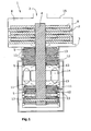
- a lubricant-free vacuum pump 1 with a suction port 2, an outlet port 3, a gas bearing rotor 16 supporting shaft 4, which is held in gas bearings 5, characterized in that at least the Shaft 4 and / or the gas bearing rotor 16 facing gas bearing surface 9 has a hard layer 10 having a layer thickness in a range of 0.5 to 30 microns of a material having a microhardness of at least 1000 HK at 0.01 N measuring force.
- the vacuum pump 1 advantageously has at least one suction opening 2 and at least one outlet opening 3 and at least one housing 15.
- at least one rotor 6 and at least one stator 7 form a lubricant-free delivery chamber 8 through which the gases to be delivered are conveyed.
- Vacuum pumps according to the invention are pumps for use in high vacuum up to pumps for use in a pre-vacuum.
- the former pumps include, for example, mechanical-kinetic vacuum pumps such as side channel blowers, turbo-compressors (axial, radial), molecular pumps and turbomolecular pumps.
- turbocompressors include, for example, turbo-radial fans such as Turbo- Stream® .
- the possibly necessary structural elements in the stator elements 11 of the gas bearings 5 can be shaped or structured, for example by exciting fine machining of the material from which the stator elements 11 are formed, so that the surface of the hard layer 10 is formed or shaped by this shaping or structuring nevertheless exactly copied.
- This can be for example a steel or aluminum alloy. Due to the small layer thickness of the hard layer, these structural elements will then be imaged exactly with the necessary precision of approximately up to 1 ⁇ m despite the hard layer 10 provided on the stator elements. Processing of the material of the hard layer 10 is therefore advantageously not required.
- the hard layer 10 itself therefore does not have to have any additional structuring in contrast to the prior art and can be substantially smooth.
- the hard layer 10 of the vacuum pump 1 according to the invention is preferably substantially smooth, as this, in contrast to the known gas bearings, a costly and expensive post-processing of the hard layer 10 such as in DE 4403340 A1 or DE 19950463 B4 is not necessary. If structuring of the resulting surface 9 is desired, this can namely in Difference to this prior art, also be created by the fact that the underlying materials 11 such as steel or aluminum alloys are much easier to work.
- the gas bearings 5 essentially consist of gas bearing stator elements 11, gas supply devices 12 and gas outlet openings 13. In this way, the formation of the gas cushion is particularly simplified.
- stator elements 11 below the hard layer 10 are preferably structured in such a way that they have inlet 12 and outlet channels 13 as the gas supply device 12 and gas outlet openings 13.
- the gas supply means 12 and gas outlet openings 13 can be integrated particularly easily into the stator elements 11.
- stator elements 11 only that part of the stator elements 11 has the hard layer 10, which faces the shaft 4 directly.
- the stator elements 11 can be made much cheaper by saving the hard materials.
- the material of the hard layer 10 is selected from carbon or hard compounds with carbon, in particular carbides, nitrides or carbonitrides of the metals Al, W, Cr or Ti.
- Such layers can be realized as single- or multi-phase layer systems up to graded layer composites.
- the layer thickness of the hard layer 10 preferably does not vary over the entire hard layer 10 by more than 10%. Through this Particularly even manufacture of the hard layer 10, the life of the vacuum pump according to the invention can be significantly increased. Therefore, the R a roughness of the hard layer 10 is advantageously up to 500 nm, in particular up to 100 nm.
- the roughness is given in R a according to DIN EN ISO 4287.
- R a in the context of the invention is the mean roughness and indicates the average distance of a measuring point on the surface to the center line. The centerline intersects the actual profile within the datum line so that the sum of the profile profile deviations relative to the centerline becomes minimal.
- a mechanical post-processing of the components after the coating is no longer necessary, in particular, if the layer thickness of the hard layer 10 according to the invention is preferably in a range of 1 to 5 ⁇ m, in particular 1 to 2.5 ⁇ m.
- the function-related tolerances of the gas storage can be kept particularly simple.
- the object underlying the invention is achieved by a method for producing a gas bearing of a vacuum pump according to the invention, in which the hard layer 10 is applied by a coating method which is selected from the group PVD, CVD, electrolysis or implantation of uncharged atoms or molecules.
- a coating method which is selected from the group PVD, CVD, electrolysis or implantation of uncharged atoms or molecules.
- PVD stands for physical vapor deposition in this case and refers to all vapor coating processes in which no chemical reaction takes place on the surface.
- CVD refers to chemical vapor coatings in which, after evaporation of so-called Precursor molecules react on the surface to certain compounds.
- the coatings 10 may (for example Dichronite ®) can be applied also, for example, by implanting uncharged atoms or molecules, if they allow sliding ideally without adhesion or abrasion under vacuum or inert dry gases.
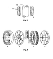
- the gas bearing 5 or the gas bearing component may be a circularly symmetrical disc of an axial gas bearing with concentrically arranged and spirally extending gas channels (see. Fig. 3 a) ,
- the component was made of an alloyed steel. In order to ensure the function of the thrust bearing component, its upper side, as well as that of the corresponding counter-disc, had to be polished.
- the surface 9 of this component was coated with a PVD hard material layer 10, as it is sold, for example, under the brand name BALINIT ® by Balzers Verschl constituentschutz GmbH, Bingen. During the start-up and the deceleration from the operating state, the two bearing discs were in contact, resulting in sliding friction.
- the component surface 9 was subjected to a cleaning pretreatment.
- a pure metallic surface 9 was achieved by ion etching with argon ions.
- a hard metal-carbon PVD layer 10 of type "ME-C: H” was then applied.
- the layer thickness was about 4 microns.
- the polished surface was reproduced exactly.
- the opposite disc was treated in the same way.
- a layer 10 having a hardness of 1000 HK with a measuring force of 0.01 N was achieved. As a result, a high resistance to adhesive wear at higher sliding speeds was achieved even under vacuum conditions. In the experiment, no wear could be found.
Landscapes
- Engineering & Computer Science (AREA)
- General Engineering & Computer Science (AREA)
- Mechanical Engineering (AREA)
- Physics & Mathematics (AREA)
- Fluid Mechanics (AREA)
- Chemical & Material Sciences (AREA)
- Ceramic Engineering (AREA)
- Structures Of Non-Positive Displacement Pumps (AREA)
- Non-Positive Displacement Air Blowers (AREA)
- Magnetic Bearings And Hydrostatic Bearings (AREA)
- Compressor (AREA)
- Sliding-Contact Bearings (AREA)
Claims (10)
- Pompe à vide sans lubrifiant (1) comprenant une ouverture d'aspiration (2), une ouverture de refoulement (3), un arbre (4) portant un rotor d'un palier à gaz et maintenu dans des paliers à gaz (5), caractérisée en ce qu'au moins la surface (9) du palier à gaz orientée vers ledit arbre (4) et/ou ledit rotor d'un palier à gaz (16) possède une couche dure (10) avec une épaisseur de couche comprise entre 0,5 et 30 µm, constituée d'un matériau ayant une microdureté d'au moins 1000 HK pour une force de mesure de 0,01 N.
- Pompe à vide (1) selon la revendication 1, caractérisée en ce qu'elle comprend des éléments (11) de palier à gaz structurés de manière à avoir des canaux d'entrée et des canaux de sortie comme dispositifs d'admission de gaz (12) et comme ouvertures de sortie de gaz (13).
- Pompe à vide (1) selon la revendication 1, caractérisée en ce que seulement la partie des éléments (11) de palier à gaz qui est directement orientée vers ledit arbre (4) possède ladite couche dure (10).
- Pompe à vide (1) selon la revendication 1, caractérisée en ce que le matériau de la couche dure (10) est choisi parmi le carbone ou les carbures, nitrures ou carbonitrures des métaux W, Cr ou Ti.
- Pompe à vide (1) selon la revendication 1, caractérisée en ce que l'épaisseur de couche de la couche dure (10) ne varie pas de plus de 10 % à travers la couche entière.
- Pompe à vide (1) selon la revendication 1, caractérisée en ce que la rugosité Ra de la couche dure (10) va jusqu'à 500 nm, notamment jusqu'à 100 nm.
- Pompe à vide (1) selon la revendication 1, caractérisée en ce que l'épaisseur de couche de la couche dure (10) est comprise entre 1 et 5 µm, notamment entre 1 et 2,5 µm.
- Procédé de production d'un palier à gaz d'une pompe à vide (1) selon l'une quelconque des revendications 1 à 7, dans lequel la couche dure (10) est appliquée par un procédé de revêtement choisi dans le groupe consistant d'un procédé de dépôt physique en phase vapeur (PVD), d'un procédé de dépôt chimique en phase vapeur (CVD), d'une électrolyse ou d'une implantation d'atomes ou de molécules non chargés.
- Procédé selon la revendication 8, caractérisée en ce qu'un procédé PVD ou CVD assisté par plasma est utilisé comme procédé de revêtement.
- Procédé selon la revendication 8, caractérisée en ce que la surface est gravée avec des ions, notamment des ions d'argon, dans une seule étape avant le revêtement.
Applications Claiming Priority (2)
| Application Number | Priority Date | Filing Date | Title |
|---|---|---|---|
| DE102006020102A DE102006020102A1 (de) | 2006-04-29 | 2006-04-29 | Beschichtung für Gaslager |
| PCT/EP2007/053811 WO2007125042A1 (fr) | 2006-04-29 | 2007-04-19 | Revetement pour palier a gaz |
Publications (2)
| Publication Number | Publication Date |
|---|---|
| EP2013484A1 EP2013484A1 (fr) | 2009-01-14 |
| EP2013484B1 true EP2013484B1 (fr) | 2013-06-19 |
Family
ID=38266251
Family Applications (1)
| Application Number | Title | Priority Date | Filing Date |
|---|---|---|---|
| EP07728273.9A Not-in-force EP2013484B1 (fr) | 2006-04-29 | 2007-04-19 | Revetement pour palier a gaz |
Country Status (7)
| Country | Link |
|---|---|
| US (1) | US8011880B2 (fr) |
| EP (1) | EP2013484B1 (fr) |
| JP (1) | JP2009535548A (fr) |
| CN (1) | CN101432526A (fr) |
| DE (1) | DE102006020102A1 (fr) |
| RU (1) | RU2008146812A (fr) |
| WO (1) | WO2007125042A1 (fr) |
Families Citing this family (10)
| Publication number | Priority date | Publication date | Assignee | Title |
|---|---|---|---|---|
| US7574486B1 (en) * | 2000-11-06 | 2009-08-11 | Telecommunication Systems, Inc. | Web page content translator |
| US8545103B1 (en) * | 2011-04-19 | 2013-10-01 | Us Synthetic Corporation | Tilting pad bearing assemblies and apparatuses, and motor assemblies using the same |
| US9263224B2 (en) | 2013-05-31 | 2016-02-16 | General Electric Company | Liquid bearing assembly and method of constructing same |
| EP3543529B1 (fr) * | 2016-11-18 | 2021-01-20 | Panasonic Intellectual Property Management Co., Ltd. | Compresseur réfrigérant et dispositif de réfrigération comprenant ce dernier |
| CN111365259A (zh) * | 2018-12-25 | 2020-07-03 | 珠海格力电器股份有限公司 | 具有扩压器供气流道的离心式压缩机和冷媒循环系统 |
| CN111486102B (zh) * | 2019-01-29 | 2022-06-14 | 青岛海尔智能技术研发有限公司 | 一种离心式压缩机和热泵系统 |
| DE102019215223A1 (de) * | 2019-10-02 | 2021-04-08 | Robert Bosch Gmbh | Axial-Gaslager |
| GB2588146A (en) * | 2019-10-09 | 2021-04-21 | Edwards Ltd | Vacuum pump |
| JP7494763B2 (ja) * | 2021-02-26 | 2024-06-04 | 株式会社豊田自動織機 | 流体機械 |
| DE102022114460A1 (de) | 2022-06-09 | 2023-12-14 | Zf Cv Systems Global Gmbh | Verdichter für ein Brennstoffzellensystem, und Brennstoffzellensystem mit selbigem |
Family Cites Families (21)
| Publication number | Priority date | Publication date | Assignee | Title |
|---|---|---|---|---|
| GB1591804A (en) * | 1977-01-10 | 1981-06-24 | British Petroleum Co | Bearing surface |
| DE3330458A1 (de) | 1983-08-24 | 1985-03-14 | The Coca-Cola Co., Atlanta, Ga. | Verschlussvorrichtung fuer lastwagen |
| DE3439648A1 (de) | 1984-10-30 | 1986-05-07 | Joachim Prof. Dr.-Ing. 8000 München Heinzl | Aerostatisches lager |
| DE3530458A1 (de) * | 1985-08-26 | 1987-03-05 | Interatom | Verfahren zur herstellung einer gasstatischen lagerung und entsprechend hergestellte lagerung |
| JPS6388314A (ja) * | 1986-09-30 | 1988-04-19 | Toshiba Corp | 動圧空気軸受 |
| US5289498A (en) | 1992-09-09 | 1994-02-22 | Echelon Corporation | Adaptive data recovery for spread spectrum systems |
| DE4300274A1 (de) | 1993-01-08 | 1994-07-14 | Leybold Ag | Vakuumpumpe mit Rotor |
| DE4403340A1 (de) | 1994-02-03 | 1995-08-10 | Heinzl Joachim | Verfahren zum Herstellen zumindest einer Mikrodüse eines aerostatischen Lagers |
| DE19725784C2 (de) | 1997-06-18 | 1999-12-16 | Gerhard Wanger | Dynamische Gaslagerung eines schnelldrehenden Werkzeugs |
| DE19821601C1 (de) | 1997-06-18 | 2000-03-16 | Gerhard Wanger | Gaslagerung einer schnelldrehenden Welle |
| EP1024294A3 (fr) * | 1999-01-29 | 2002-03-13 | Ibiden Co., Ltd. | Moteur et pompe turbomoléculaire |
| DE19915983A1 (de) | 1999-04-09 | 2000-10-12 | Pfeiffer Vacuum Gmbh | Vakuumpumpe mit Gaslagerung |
| DE19950463B4 (de) | 1999-10-20 | 2004-04-15 | Precision Motors Deutsche Minebea Gmbh | Verfahren zur Herstellung hydrodynamischen Gleitlagers für einen Spindelmotor und ein nach dem Verfahren hergestelltes hydrodynamisches Gleitlager |
| DE10037077A1 (de) | 2000-07-27 | 2002-02-28 | Paul Mueller Gmbh & Co Kg | Dynamische Gaslagerung einer Motorspindel mit Entlüftung |
| DE10053663A1 (de) | 2000-10-28 | 2002-05-08 | Leybold Vakuum Gmbh | Mechanische kinetische Vakuumpumpe mit Rotor und Welle |
| DE202004010821U1 (de) * | 2003-07-23 | 2004-12-23 | The Boc Group Plc, Windlesham | Vakuumpumpenbauteil |
| US20090098002A1 (en) * | 2005-09-20 | 2009-04-16 | Kudu Industries Inc. | Process for hardfacing a metal body |
| US20080069715A1 (en) * | 2006-09-20 | 2008-03-20 | Kudu Industries Inc. | Process for hardfacing a progressing cavity pump/motor rotor |
| US20070071921A1 (en) * | 2005-09-20 | 2007-03-29 | James Coulas | Process for hardfacing a progressing cavity pump/motor rotor |
| JP2009133218A (ja) * | 2007-11-28 | 2009-06-18 | Showa Corp | ベーンポンプ |
| CN102002684B (zh) * | 2009-08-31 | 2014-07-30 | 日立金属株式会社 | 滑动部件 |
-
2006
- 2006-04-29 DE DE102006020102A patent/DE102006020102A1/de not_active Withdrawn
-
2007
- 2007-04-19 US US12/298,547 patent/US8011880B2/en not_active Expired - Fee Related
- 2007-04-19 RU RU2008146812/06A patent/RU2008146812A/ru not_active Application Discontinuation
- 2007-04-19 EP EP07728273.9A patent/EP2013484B1/fr not_active Not-in-force
- 2007-04-19 JP JP2009507037A patent/JP2009535548A/ja not_active Withdrawn
- 2007-04-19 CN CNA2007800155513A patent/CN101432526A/zh active Pending
- 2007-04-19 WO PCT/EP2007/053811 patent/WO2007125042A1/fr active Application Filing
Also Published As
| Publication number | Publication date |
|---|---|
| CN101432526A (zh) | 2009-05-13 |
| RU2008146812A (ru) | 2010-06-10 |
| DE102006020102A1 (de) | 2007-10-31 |
| EP2013484A1 (fr) | 2009-01-14 |
| US20100202880A1 (en) | 2010-08-12 |
| US8011880B2 (en) | 2011-09-06 |
| WO2007125042A1 (fr) | 2007-11-08 |
| JP2009535548A (ja) | 2009-10-01 |
Similar Documents
| Publication | Publication Date | Title |
|---|---|---|
| EP2013484B1 (fr) | Revetement pour palier a gaz | |
| EP1767662B1 (fr) | Revêtement résistant à l'usure et procédé pour sa fabrication | |
| DE60103152T2 (de) | Lager mit amorpher borcarbidbeschichtung | |
| CN1123703C (zh) | 带有涂层的滚动元件轴承 | |
| JPH01279119A (ja) | 機械部材 | |
| WO2014063676A1 (fr) | Composant doté d'un revêtement et procédé pour le fabriquer | |
| AT510190B1 (de) | Verfahren zum herstellen eines mehrschichtigen gleitlagers | |
| EP0816698A1 (fr) | Dispositifs à contact de roulement lubrifiés, méthode pour les lubrifier et composition adaptée à une telle lubrification | |
| CH706054A2 (de) | Verfahren zum Herstellen eines mehrschichtigen Gleitlagers, sowie ein Gleitlager umfassend eine Stützschicht und eine Gleitschicht. | |
| CN1625656A (zh) | 含油烧结滑动轴承 | |
| JP2009133408A (ja) | 転がり摺動部材およびこれを用いた転動装置ならびにプーリ装置 | |
| EP1837418A1 (fr) | Revêtement en carbone à dureté élevée | |
| EP3207268B1 (fr) | Palier oléophile présentant une partie à surface modifiée en acier à roulement non oxydable | |
| US7281853B2 (en) | Bearing material | |
| US20010005436A1 (en) | Arrangement in an air bearing | |
| JP2009007935A (ja) | ターボチャージャ | |
| US6087009A (en) | Surface treating methods | |
| WO2004055402A1 (fr) | Palier a roulement a materiau lubrifiant integre | |
| EP0571481B1 (fr) | Paliers | |
| EP3916237B1 (fr) | Pompe centrifuge pourvue d'au moins un dispositif palier lisse hydrodynamique | |
| RU2230238C1 (ru) | Антифрикционное покрытие | |
| Recanati et al. | Engineering the next generation of carbon based (DLC) coatings for demanding applications | |
| JP2008151264A (ja) | 転がり軸受用保持器 | |
| DE202007012053U1 (de) | Turbomaschine | |
| DE102006027501A1 (de) | Verschleißfeste Beschichtung und Verfahren zur Herstellung derselben |
Legal Events
| Date | Code | Title | Description |
|---|---|---|---|
| PUAI | Public reference made under article 153(3) epc to a published international application that has entered the european phase |
Free format text: ORIGINAL CODE: 0009012 |
|
| 17P | Request for examination filed |
Effective date: 20081014 |
|
| AK | Designated contracting states |
Kind code of ref document: A1 Designated state(s): AT BE BG CH CY CZ DE DK EE ES FI FR GB GR HU IE IS IT LI LT LU LV MC MT NL PL PT RO SE SI SK TR |
|
| AX | Request for extension of the european patent |
Extension state: AL BA HR MK RS |
|
| RIN1 | Information on inventor provided before grant (corrected) |
Inventor name: FROITZHEIM, MICHAEL Inventor name: BLUMENTHAL, ROLAND |
|
| DAX | Request for extension of the european patent (deleted) | ||
| RBV | Designated contracting states (corrected) |
Designated state(s): CH DE FR GB IT LI |
|
| GRAP | Despatch of communication of intention to grant a patent |
Free format text: ORIGINAL CODE: EPIDOSNIGR1 |
|
| GRAS | Grant fee paid |
Free format text: ORIGINAL CODE: EPIDOSNIGR3 |
|
| GRAA | (expected) grant |
Free format text: ORIGINAL CODE: 0009210 |
|
| AK | Designated contracting states |
Kind code of ref document: B1 Designated state(s): CH DE FR GB IT LI |
|
| REG | Reference to a national code |
Ref country code: GB Ref legal event code: FG4D Free format text: NOT ENGLISH |
|
| REG | Reference to a national code |
Ref country code: CH Ref legal event code: EP |
|
| REG | Reference to a national code |
Ref country code: DE Ref legal event code: R096 Ref document number: 502007011925 Country of ref document: DE Effective date: 20130814 |
|
| PLBE | No opposition filed within time limit |
Free format text: ORIGINAL CODE: 0009261 |
|
| STAA | Information on the status of an ep patent application or granted ep patent |
Free format text: STATUS: NO OPPOSITION FILED WITHIN TIME LIMIT |
|
| 26N | No opposition filed |
Effective date: 20140320 |
|
| PG25 | Lapsed in a contracting state [announced via postgrant information from national office to epo] |
Ref country code: IT Free format text: LAPSE BECAUSE OF FAILURE TO SUBMIT A TRANSLATION OF THE DESCRIPTION OR TO PAY THE FEE WITHIN THE PRESCRIBED TIME-LIMIT Effective date: 20130619 |
|
| REG | Reference to a national code |
Ref country code: DE Ref legal event code: R097 Ref document number: 502007011925 Country of ref document: DE Effective date: 20140320 |
|
| PGFP | Annual fee paid to national office [announced via postgrant information from national office to epo] |
Ref country code: GB Payment date: 20140423 Year of fee payment: 8 |
|
| PGFP | Annual fee paid to national office [announced via postgrant information from national office to epo] |
Ref country code: FR Payment date: 20140416 Year of fee payment: 8 Ref country code: DE Payment date: 20140627 Year of fee payment: 8 |
|
| REG | Reference to a national code |
Ref country code: CH Ref legal event code: PL |
|
| PG25 | Lapsed in a contracting state [announced via postgrant information from national office to epo] |
Ref country code: CH Free format text: LAPSE BECAUSE OF NON-PAYMENT OF DUE FEES Effective date: 20140430 Ref country code: LI Free format text: LAPSE BECAUSE OF NON-PAYMENT OF DUE FEES Effective date: 20140430 |
|
| REG | Reference to a national code |
Ref country code: DE Ref legal event code: R119 Ref document number: 502007011925 Country of ref document: DE |
|
| GBPC | Gb: european patent ceased through non-payment of renewal fee |
Effective date: 20150419 |
|
| PG25 | Lapsed in a contracting state [announced via postgrant information from national office to epo] |
Ref country code: DE Free format text: LAPSE BECAUSE OF NON-PAYMENT OF DUE FEES Effective date: 20151103 Ref country code: GB Free format text: LAPSE BECAUSE OF NON-PAYMENT OF DUE FEES Effective date: 20150419 |
|
| REG | Reference to a national code |
Ref country code: FR Ref legal event code: ST Effective date: 20151231 |
|
| PG25 | Lapsed in a contracting state [announced via postgrant information from national office to epo] |
Ref country code: FR Free format text: LAPSE BECAUSE OF NON-PAYMENT OF DUE FEES Effective date: 20150430 |