EP2013468B1 - Injector - Google Patents
Injector Download PDFInfo
- Publication number
- EP2013468B1 EP2013468B1 EP07726724A EP07726724A EP2013468B1 EP 2013468 B1 EP2013468 B1 EP 2013468B1 EP 07726724 A EP07726724 A EP 07726724A EP 07726724 A EP07726724 A EP 07726724A EP 2013468 B1 EP2013468 B1 EP 2013468B1
- Authority
- EP
- European Patent Office
- Prior art keywords
- injector
- actuator
- contour
- sealing
- nozzle needle
- Prior art date
- Legal status (The legal status is an assumption and is not a legal conclusion. Google has not performed a legal analysis and makes no representation as to the accuracy of the status listed.)
- Not-in-force
Links
- 238000007789 sealing Methods 0.000 claims abstract description 56
- 239000000446 fuel Substances 0.000 claims abstract description 17
- 238000002347 injection Methods 0.000 claims abstract description 16
- 239000007924 injection Substances 0.000 claims abstract description 16
- 230000036316 preload Effects 0.000 claims description 5
- 238000002485 combustion reaction Methods 0.000 claims description 3
- 239000007921 spray Substances 0.000 claims description 3
- 230000003213 activating effect Effects 0.000 claims 1
- 230000003993 interaction Effects 0.000 description 3
- 238000004519 manufacturing process Methods 0.000 description 3
- 210000002435 tendon Anatomy 0.000 description 3
- 230000000295 complement effect Effects 0.000 description 1
- 230000006835 compression Effects 0.000 description 1
- 238000007906 compression Methods 0.000 description 1
- 238000010276 construction Methods 0.000 description 1
- 238000007667 floating Methods 0.000 description 1
- 238000000034 method Methods 0.000 description 1
- 230000000284 resting effect Effects 0.000 description 1
- 238000007493 shaping process Methods 0.000 description 1
- 238000004904 shortening Methods 0.000 description 1
Images


Classifications
-
- F—MECHANICAL ENGINEERING; LIGHTING; HEATING; WEAPONS; BLASTING
- F02—COMBUSTION ENGINES; HOT-GAS OR COMBUSTION-PRODUCT ENGINE PLANTS
- F02M—SUPPLYING COMBUSTION ENGINES IN GENERAL WITH COMBUSTIBLE MIXTURES OR CONSTITUENTS THEREOF
- F02M51/00—Fuel-injection apparatus characterised by being operated electrically
- F02M51/06—Injectors peculiar thereto with means directly operating the valve needle
- F02M51/0603—Injectors peculiar thereto with means directly operating the valve needle using piezoelectric or magnetostrictive operating means
-
- F—MECHANICAL ENGINEERING; LIGHTING; HEATING; WEAPONS; BLASTING
- F02—COMBUSTION ENGINES; HOT-GAS OR COMBUSTION-PRODUCT ENGINE PLANTS
- F02M—SUPPLYING COMBUSTION ENGINES IN GENERAL WITH COMBUSTIBLE MIXTURES OR CONSTITUENTS THEREOF
- F02M51/00—Fuel-injection apparatus characterised by being operated electrically
- F02M51/005—Arrangement of electrical wires and connections, e.g. wire harness, sockets, plugs; Arrangement of electronic control circuits in or on fuel injection apparatus
-
- F—MECHANICAL ENGINEERING; LIGHTING; HEATING; WEAPONS; BLASTING
- F02—COMBUSTION ENGINES; HOT-GAS OR COMBUSTION-PRODUCT ENGINE PLANTS
- F02M—SUPPLYING COMBUSTION ENGINES IN GENERAL WITH COMBUSTIBLE MIXTURES OR CONSTITUENTS THEREOF
- F02M55/00—Fuel-injection apparatus characterised by their fuel conduits or their venting means; Arrangements of conduits between fuel tank and pump F02M37/00
- F02M55/004—Joints; Sealings
Definitions
- the present invention relates to an injector for supplying fuel to an internal combustion engine, in particular in a motor vehicle, having the features of the preamble of claim 1.
- Injectors of this type are for example from the DE 10 2004 027 824 A1 and from the EP 1 174 615 A2 are known and each comprise a piezoelectric actuator for driving or actuating at least one nozzle needle, with the aid of which an injection of high-pressure fuel is controlled by at least one injection hole.
- the piezoelectric actuator has a shaft which expands in its "energization” in its longitudinal direction and which resumes its original, shortened length in a "Entstromung”.
- An injector body of the injector contains an actuator space in which the piezoelectric actuator is arranged with its shaft.
- a high-pressure path which leads the high-pressure fuel to the at least one injection hole, is passed through said actuator space.
- the piezoelectric actuator is surrounded by the fuel under high pressure;
- the piezoelectric actuator is arranged “wet” or "floating".
- the injectors can be driven by energizing and Entström the piezoelectric actuator, a control piston to lower the pressure in a control chamber for opening the nozzle needle.
- This is a direct, pressure controlled Needle control.
- an inversely operated piezoelectric actuator it is de-energized to open the nozzle needle while it is energized when the nozzle needle is closed (eg WO 2005/121544 ).
- the piezoelectric actuator directly to drive the nozzle needle or a needle assembly comprising the nozzle needle or, for example, to control a servo valve.
- other designs for injectors with piezoelectric actuator are conceivable.
- the injector according to the invention with the features of claim 1 has the advantage that the alignment of the piezoelectric actuator relative to the injector body is improved during assembly of the injector via the interaction of a sealing contour formed on an actuator body with a sealing seat formed on the injector body. It is of particular importance that the sealing contour of the actuator base of the nozzle needle faces and sits axially in the direction of the nozzle needle in the sealing seat. In particular, this makes it possible to match the sealing contour and the sealing seat to one another such that the actuator foot, with its sealing contour in the sealing seat, forms an actuator space seal closing the actuator space. Depending on which axial force the sealing contour in the sealing seat sits, a more or less effective seal of the actuator space can be achieved to the outside.
- the actuator foot is biased by means of a biasing device in the direction of the nozzle needle, such that the sealing contour is biased in the sealing seat.
- a biasing device By selecting this axial preload, the tightness of the actuator chamber seal can be adjusted to the particular desired pressure value.
- the biasing device can also be designed so that it is designed to initiate a bias that is so great that it leads to plastic deformation of the sealing seat and / or on the sealing contour. In such an embodiment, even the smallest form deviations can be compensated by the deformation in order to improve the effectiveness of the actuator chamber seal.
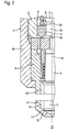
- Fig. 1 to 3 comprises an injector 1 of an injection device, which for supplying an internal combustion engine, in particular in a motor vehicle, with fuel serves, an injector body 2, in which at least one nozzle needle 3 and a nozzle needle 3 comprehensive nozzle body 4 is arranged.
- the nozzle body 4 is fixed by means of an overspent nozzle retaining nut 46 on the rest of the injector body 2.
- the injector 1 comprises a piezoactuator 5 with an actuator foot 6, an actuator shaft 7 and an actuator head 8.
- the injector body 2 contains an actuator chamber 9, in which the piezoactuator 5 is arranged at least with its shaft 7.
- a high pressure path 10 is also formed, which leads from a trained on the injector 2 high pressure port 11 of the injector 1 to at least one also formed on the nozzle body 4 injection hole 12 of the injector 1 and in operation of the injector 1 under high pressure fuel for at least one Spray hole 12 leads.
- the high-pressure path 10 is moved through the actuator chamber 9, that is, the actuator chamber 9 forms part of the high-pressure path 10 and is flowed through by the high-pressure fuel.
- the piezoelectric actuator 5 is used to control or to actuate the nozzle needle 3, such that with the nozzle needle 3, the injection of high-pressure fuel through the at least one injection hole 12 in a respective injector 1 associated injection chamber 13 is controllable.
- the nozzle needle 3 cooperates with a needle seat 14 in a known manner.
- the pressure is lowered in a control chamber 16 by a corresponding actuation of the piezoelectric actuator 5.
- Said control chamber 16 is limited in the radial direction by a control sleeve 17.
- control chamber 16 In the axial direction of the control chamber 16 is limited to the nozzle needle 3 through an intermediate plate 18 and the piezoelectric actuator 5 through a control piston 19.
- the control piston 19 is firmly connected to the actuator head 8 and immersed in the control sleeve 17 a.
- the control sleeve 17 is mounted on the control piston 19 adjustable in stroke and supported by a closing compression spring 20 on the actuator head 8. About the closing pressure spring 20, the control sleeve 17 is axially biased against the intermediate plate 18.
- the piezoelectric actuator 5 may be operated inversely, for example. That is, in the initial state shown, in which the nozzle needle 3 is seated in the needle seat 14 and assumes its closed position, the piezoelectric actuator 5 is energized and is thus axially expanded. To open the nozzle needle 3, the piezoelectric actuator 5 is de-energized, whereby it is parallel to the longitudinal axis 15 measured length reduced. Since the actuator foot 6 is fixedly arranged on the injector body 2, the actuator head 8 retracts from the nozzle needle 3 during the shortening of the actuator shaft 7. As a result, the control piston 19 is moved away from the, nozzle needle 3, whereby the pressure in the control chamber 16 drops. As a result, the pressure-controlled nozzle needle 3 can lift off the needle seat 14 and the injection process begins.
- the actuator foot 6 has a sealing contour 21 which faces the nozzle needle 3 and bears against a sealing seat 22 which faces away from the nozzle needle 3 and at the injector body 2 is formed. As a result, the actuator foot 6 can be supported axially on the injector body 2 in the direction of the nozzle needle 3.
- sealing contour 21 and sealing seat 22 are matched to one another such that the actuator foot 6 forms, together with its sealing contour 21 in the sealing seat 22, an actuator space seal 23 which closes the actuator space 9.
- the sealing contour 21 and the sealing seat 22 are each designed annularly closed, wherein they rotate with respect to the longitudinal axis 15 in the circumferential direction.
- sealing contour 21 and sealing seat 22 are preferably aligned concentrically to the longitudinal axis 15.
- the sealing contour 21 and the sealing seat 22 can also be utilized to align the piezoactuator 5 as exactly as possible concentrically with the longitudinal central axis 15 during assembly of the injector 1.
- the sealing contour 21 is designed spherical, such that the sealing contour 21 extends spherically along a spherical section.
- the associated virtual sphere is designated 24 in the figures.
- a center 25 of the ball 24 is arranged centrally in the actuator base 6.
- the spherical sealing contour 21 simplifies the axial alignment of the piezoelectric actuator 5 relative to the injector body 2, whereby the functionality of the interaction between the control sleeve 17 and the control piston 19 is improved. This design is particularly advantageous when the piezoelectric actuator 5 has a comparatively long shaft 7, for example, in Fig. 1 is clearly shortened.
- the sealing seat 22 preferably has a conical shape, whereby a linear contact between sealing contour 21 and sealing seat 22 is achieved regardless of manufacturing tolerances. As a result, a closed and thus effective Aktorraumdichtung 23 is realized.
- the actuator foot 6 is prestressed in the direction of the nozzle needle 3, as a result of which the sealing contour 21 is seated with axial prestress in the sealing seat 22.
- the selected axial preload can be comparatively large, for example, the set preload can be so large that it comes to tolerated plastic deformation of the sealing seat 22 and / or on the sealing contour 21.
- the above-mentioned linear contact between sealing contour 21 and sealing seat 22 is thereby virtually strip-shaped.
- the injector 1 is equipped with a pretensioning device 26.
- the biasing means 26 comprises a clamping screw 27 and a clamping member 28, wherein it is also possible in principle, the here separately formed clamping member 28 integrally formed on the clamping screw 27 and to form the clamping member 28 by the clamping screw 27.
- a clamping screw 27 and a clamping nut can be used instead of a clamping screw 27 and a clamping nut.
- the tendon 28 has a support seat 29 which faces the nozzle needle 3.
- a support contour 30 is formed on a side facing away from the nozzle needle 3, which abuts axially in the support seat 29 and is supported.
- the support contour 30 and the support seat 29 closed in an annular manner and preferably to arrange it concentrically with respect to the longitudinal axis 15.
- the support contour 30 then extends spherically in a spherical section.
- the support contour 30 associated ball may have a different radius than the sealing contour 21 associated ball.
- the balls of the two contours 21, 30 are the same size and are preferably identical. That is, in the example shown, the spherical support contour 30 is also on the virtual ball 24 with the center 25th
- the support seat 29 is preferably configured conical, whereby a linear contact is achieved between the support contour 30 and support seat 29. Depending on the biasing force, plastic deformation may also occur on the support seat 29 and / or on the support contour 30.
- the clamping screw 27 has an external thread 31 which cooperates with a complementary internal thread 32 which is formed on the injector body 2. Thus, the clamping screw 27 is axially screwed into the injector 2. The clamping screw 27 presses the clamping member 28 in the axial direction against the actuator base. 6
- the tendon 28 may be secured by means of a rotation lock 33 against a rotational adjustment about the longitudinal axis 15.
- the anti-rotation device 33 is formed by a locking pin 34 which is supported on the injector body 2 and engages radially in a securing slot 35 formed on the outside of the tensioning element 28.
- the tendon 28 is preferably annular, thereby including a central opening 36.
- the clamping screw 27 may be configured as sleeve-shaped here, whereby it has a central passage 37. Opening 36 and passage 37 form a connection channel 38, through which electrical connections 39 of the piezoelectric actuator 5 to the actuator foot 6 and through the actuator foot 6 are led through to the actuator shaft 7 equipped with the piezoelectric elements.
- the actuator foot 6 together with its support seat 29 resting on the support contour 30 form a connection channel seal 45, which closes the connection channel 38 on the actuator foot 6 to the outside.
- the injector 1 is characterized in particular by the fact that its piezoactuator 5 can be aligned relatively exactly axially parallel to the longitudinal axis 15 during assembly, which is achieved by the targeted shaping and interaction of sealing contour 21 and sealing seat 22. Furthermore, with the help of the clamping member 28, which is secured against rotation on the injector body 2, the introduction of very high biasing forces on the clamping screw 27 allows, without causing a change in the set orientation between the piezoelectric actuator 5 and injector 2. Because the rotational movement of the clamping screw 27 is not transmitted to the actuator base 6 via the non-rotatable clamping member 28.
- the injector 1 can be connected to a high-pressure source which provides the high-pressure fuel.
- the high pressure port 11 is connected to a high pressure line, which in turn is connected to a high pressure pump. If a plurality of injectors 1 is connected to a common high pressure line, it is a so-called "common rail system".
- the injector body 2 is made in one piece in the region containing the actuator chamber 9.
- the injector body 2 is made in the area surrounding the actuator chamber 9 at least in two parts or assembled from two parts, namely from a first injector body part 40 and from a second injector body part 41.
- the first injector body part 40 contains the actuator foot 6.
- the second injector body part 41 adjoins the first injector body part 40 in the direction of the nozzle needle 3.
- the second injector body part 41 contains the entire or at least a substantial proportion of the actuator chamber 9.
- the first injector body part 40 may contain a comparatively small proportion of the actuator chamber 9.
- the high-pressure port 11 is formed on the first injector body part 40.
- the two injector body parts 40, 41 are fastened to one another via a connecting element 42, which may be designed in particular sleeve-shaped.
- a connecting element 42 which may be designed in particular sleeve-shaped.
- an annular seal 44 is additionally provided here.
- the second injector body part 41 As a standard component, which is used identically in different variants of the injector 1.
- the first injector body part 40 can then be designed differently for different variants of the injector 1.
- different variants of the injector 1 can then be realized comparatively inexpensively.
Landscapes
- Engineering & Computer Science (AREA)
- Chemical & Material Sciences (AREA)
- Combustion & Propulsion (AREA)
- Mechanical Engineering (AREA)
- General Engineering & Computer Science (AREA)
- Fuel-Injection Apparatus (AREA)
- Glass Compositions (AREA)
- Disintegrating Or Milling (AREA)
- Jellies, Jams, And Syrups (AREA)
Abstract
Description
Die vorliegende Erfindung betrifft einen Injektor zur Kraftstoffversorgung einer Brennkraftmaschine, insbesondere in einem Kraftfahrzeug, mit den Merkmalen des Oberbegriffs des Anspruchs 1.The present invention relates to an injector for supplying fuel to an internal combustion engine, in particular in a motor vehicle, having the features of the preamble of claim 1.
Injektoren dieser Art sind beispielsweise aus der
Bei den bekannten Injektoren kann durch Bestromen und Entstromen des Piezoaktors ein Steuerkolben angetrieben werden, um in einem Steuerraum zum Öffnen der Düsennadel den Druck abzusenken. Hierbei handelt es sich um eine direkte, druckgesteuerte Nadelsteuerung. Bei einem invers betriebenen Piezoaktor wird er zum Öffnen der Düsennadel entstromt, während er bei geschlossener Düsennadel bestromt ist (z.B.
Bei anderen Bauformen von Injektoren ist es ebenso möglich, den Piezoaktor direkt zum Antreiben der Düsennadel oder eines die Düsennadel umfassenden Nadelverbands zu verwenden oder beispielsweise um ein Servoventil anzusteuern. Des Weiteren sind auch andere Bauformen für Injektoren mit Piezoaktor denkbar.In other types of injectors, it is also possible to use the piezoelectric actuator directly to drive the nozzle needle or a needle assembly comprising the nozzle needle or, for example, to control a servo valve. Furthermore, other designs for injectors with piezoelectric actuator are conceivable.
Bei der oben erwähnten direkten Nadelsteuerung ist es zur Reduzierung von hydraulischen Übersetzungseinrichtungen erforderlich, den Piezoaktor mit einem relativ langen Schaft zu versehen, um die erforderlichen Hübe realisieren zu können. Bei der Herstellung des Piezoaktors und des Injektorkörpers lassen sich jedoch aufgrund von Herstellungstoleranzen Plan- und Rundlaufabweichungen nicht vermeiden, die zu einem Achs- und Winkelversatz der miteinander zusammenwirkenden Komponenten führen können. Zur Erzielung einer effektiven Abdichtung des Aktorraums nach außen, ist jedoch eine möglichst exakte Winkelausrichtung des Piezoaktors innerhalb des Injektorkörpers erforderlich. Diese Anforderung wird immer wichtiger, je höher der Hochdruck zur Beaufschlagung des Kraftstoffs gewählt wird. Zwischenzeitlich kann der Kraftstoff bei modernen Einspritzanlagen mit einem Hochdruck von 2.000 bar beaufschlagt werden. Für den Injektor wird dann beispielsweise eine Druckdichtheit nach außen bis ca. 2.400 bar erwünscht, um auch bei im Betrieb auftretenden, dynamischen Druckspitzen Leckagen vermeiden zu können.In the case of the above-mentioned direct needle control, in order to reduce hydraulic translation devices, it is necessary to provide the piezoelectric actuator with a relatively long shaft in order to be able to realize the required strokes. In the production of the piezoelectric actuator and the injector body, however, plan and concentricity deviations due to manufacturing tolerances can not be avoided, which can lead to an axial and angular offset of the interacting components. To achieve an effective seal of the actuator space to the outside, however, the most accurate angular orientation of the piezoelectric actuator within the injector body is required. This requirement becomes more important the higher the high pressure is selected to apply to the fuel. In the meantime, the fuel in modern injection systems with a high pressure of 2,000 bar can be applied. For the injector then, for example, a pressure tightness to the outside to about 2,400 bar is desired in order to avoid leaks even when occurring during operation, dynamic pressure peaks.
Der erfindungsgemäße Injektor mit den Merkmalen des Anspruchs 1 hat den Vorteil, dass über das Zusammenwirken einer an einem Aktorfuss ausgebildeten Dichtkontur mit einem am Injektorkörper ausgebildeten Dichtsitz die Ausrichtbarkeit des Piezoaktors gegenüber dem Injektorkörper während der Montage des Injektors verbessert ist. Dabei ist von besonderer Bedeutung, dass die Dichtkontur des Aktorfusses der Düsennadel zugewandt ist und axial in Richtung zur Düsennadel im Dichtsitz sitzt. Insbesondere ist es dadurch möglich, Dichtkontur und Dichtsitz so aufeinander abzustimmen, dass der Aktorfuss mit seiner im Dichtsitz anliegenden Dichtkontur eine den Aktorraum verschließende Aktorraumdichtung bildet. Je nachdem mit welcher Axialkraft die Dichtkontur im Dichtsitz sitzt, lässt sich eine mehr oder weniger effektive Abdichtung des Aktorraums nach außen erzielen.The injector according to the invention with the features of claim 1 has the advantage that the alignment of the piezoelectric actuator relative to the injector body is improved during assembly of the injector via the interaction of a sealing contour formed on an actuator body with a sealing seat formed on the injector body. It is of particular importance that the sealing contour of the actuator base of the nozzle needle faces and sits axially in the direction of the nozzle needle in the sealing seat. In particular, this makes it possible to match the sealing contour and the sealing seat to one another such that the actuator foot, with its sealing contour in the sealing seat, forms an actuator space seal closing the actuator space. Depending on which axial force the sealing contour in the sealing seat sits, a more or less effective seal of the actuator space can be achieved to the outside.
Besonders vorteilhaft ist eine Weiterbildung, bei welcher der Aktorfuss mittels einer Vorspanneinrichtung in Richtung auf die Düsennadel vorgespannt ist, derart, dass die Dichtkontur unter Vorspannung im Dichtsitz anliegt. Durch Auswahl dieser axialen Vorspannung lässt sich die Dichtigkeit der Aktorraumdichtung auf den jeweils gewünschten Druckwert einstellen. Insbesondere kann die Vorspanneinrichtung auch so ausgestaltet sein, dass sie zur Einleitung einer Vorspannung ausgestaltet ist, die so groß ist, dass sie zu plastischen Verformungen am Dichtsitz und/oder an der Dichtkontur führt. Bei einer derartigen Ausführungsform lassen sich durch die Verformung auch kleinste Formabweichungen ausgleichen, um die Effektivität der Aktorraumdichtung zu verbessern.Particularly advantageous is a development in which the actuator foot is biased by means of a biasing device in the direction of the nozzle needle, such that the sealing contour is biased in the sealing seat. By selecting this axial preload, the tightness of the actuator chamber seal can be adjusted to the particular desired pressure value. In particular, the biasing device can also be designed so that it is designed to initiate a bias that is so great that it leads to plastic deformation of the sealing seat and / or on the sealing contour. In such an embodiment, even the smallest form deviations can be compensated by the deformation in order to improve the effectiveness of the actuator chamber seal.
Weitere wichtige Merkmale und Vorteile des erfindungsgemäßen Injektors ergeben sich aus den Unteransprüchen, aus den Zeichnungen und aus der zugehörigen Figurenbeschreibung anhand der Zeichnungen.Further important features and advantages of the injector according to the invention will become apparent from the subclaims, from the drawings and from the associated description of the figures with reference to the drawings.
Ausführungsbeispiele des erfindungsgemäßen Injektors sind in den Zeichnungen dargestellt und werden im folgenden näher erläutert, wobei sich gleiche Bezugszeichen auf gleiche oder ähnliche oder funktional gleiche Komponenten beziehen. Es zeigen, jeweils schematisch,
- Fig. 1
- einen vereinfachten Längsschnitt durch einen Injektor,
- Fig. 2
- eine vergrößerte Darstellung im Halbschnitt eines Ausschnitts II aus
Fig. 1 , - Fig. 3
- eine weiter vereinfachte Darstellung im Längsschnitt eines Injektors, jedoch bei einer anderen Ausführungsform.
- Fig. 1
- a simplified longitudinal section through an injector,
- Fig. 2
- an enlarged view in half section of a section II
Fig. 1 . - Fig. 3
- a further simplified representation in longitudinal section of an injector, but in another embodiment.
Entsprechend den
Im Injektorkörper 2 ist außerdem ein Hochdruckpfad 10 ausgebildet, der von einem am Injektorkörper 2 ausgebildeten Hochdruckanschluss 11 des Injektors 1 bis zu wenigstens einem ebenfalls am Düsenkörper 4 ausgebildeten Spritzloch 12 des Injektors 1 führt und im Betrieb des Injektors 1 unter Hochdruck stehenden Kraftstoff zum wenigstens einen Spritzloch 12 führt. Der Hochdruckpfad 10 ist durch den Aktorraum 9 hindurch gerührt, das heißt, der Aktorraum 9 bildet einen Bestandteil des Hochdruckpfads 10 und ist von dem unter Hochdruck stehenden Kraftstoff durchströmt.In the
Der Piezoaktor 5 dient zum Ansteuern bzw. zum Betätigen der Düsennadel 3, derart, dass mit der Düsennadel 3 die Einspritzung des unter Hochdruck stehenden Kraftstoffs durch das wenigstens eine Spritzloch 12 in einen dem jeweiligen Injektor 1 zugeordneten Einspritzraum 13 steuerbar ist. Zum Steuern der Einspritzung durch das wenigstens eine Spritzloch 12 wirkt die Düsennadel 3 mit einem Nadelsitz 14 in bekannter Weise zusammen. Um die Düsennadel 3 aus dem Nadelsitz 14 herauszufahren, muss sie einen Öffnungshub parallel zu einer Längsachse 15 des Injektors 1 bzw. des Injektorkörpers 2 durchführen. Hierzu wird in einem Steuerraum 16 durch eine entsprechende Betätigung des Piezoaktors 5 der Druck abgesenkt. Besagter Steuerraum 16 ist in radialer Richtung von einer Steuerhülse 17 begrenzt. In axialer Richtung ist der Steuerraum 16 zur Düsennadel 3 hin durch eine Zwischenplatte 18 und zum Piezoaktor 5 hin durch einen Steuerkolben 19 begrenzt. Der Steuerkolben 19 ist mit dem Aktorkopf 8 fest verbunden und taucht in die Steuerhülse 17 ein. Die Steuerhülse 17 ist am Steuerkolben 19 hubverstellbar gelagert und über eine Schließdruckfeder 20 am Aktorkopf 8 abgestützt. Über die Schließdruckfeder 20 ist die Steuerhülse 17 gegen die Zwischenplatte 18 axial vorgespannt.The
Der Piezoaktor 5 kann beispielsweise invers betrieben sein. Das heißt, im gezeigten Ausgangszustand, bei dem die Düsennadel 3 im Nadelsitz 14 sitzt und ihre Schließstellung einnimmt, ist der Piezoaktor 5 bestromt und ist dadurch axial ausgedehnt. Zum Öffnen der Düsennadel 3 wird der Piezoaktor 5 entstromt, wodurch sich seine parallel zur Längsachse 15 gemessene Länge reduziert. Da der Aktorfuss 6 ortsfest am Injektorkörper 2 angeordnet ist, zieht sich bei der Verkürzung des Aktorschafts 7 der Aktorkopf 8 von der Düsennadel 3 zurück. Hierdurch wird der Steuerkolben 19 von der, Düsennadel 3 wegbewegt, wodurch der Druck im Steuerraum 16 abfällt. In der Folge kann die druckgesteuerte Düsennadel 3 vom Nadelsitz 14 abheben und der Einspritzvorgang beginnt.The
Um den Piezoaktor 5 im Bereich seines Aktorfusses 6 am Injektorkörper 2 ortsfest abstützen zu können, weist der Aktorfuss 6 eine Dichtkontur 21 auf, die der Düsennadel 3 zugewandt ist und die in einem Dichtsitz 22 anliegt, der von der Düsennadel 3 abgewandt ist und am Injektorkörper 2 ausgebildet ist. Hierdurch kann sich der Aktorfuss 6 in Richtung zur Düsennadel 3 axial am Injektorkörper 2 abstützen.To be able to support the
Vorzugsweise sind Dichtkontur 21 und Dichtsitz 22 so aufeinander abgestimmt, dass der Aktorfuss 6 zusammen mit seiner im Dichtsitz 22 anliegenden Dichtkontur 21 eine Aktorraumdichtung 23 bildet, die den Aktorraum 9 verschließt. Mit Hilfe dieser Aktorraumdichtung 23 wird dabei der Aktorraum 9 an seinem von der Düsennadel 3 abgewandten Ende axial verschlossen. Um die gewünschte Aktorraumdichtung 23 zu realisieren, sind die Dichtkontur 21 und der Dichtsitz 22 jeweils ringförmig geschlossen ausgestaltet, wobei sie bezüglich der Längsachse 15 in Umfangsrichtung umlaufen. Des Weiteren sind Dichtkontur 21 und Dichtsitz 22 vorzugsweise konzentrisch zur Längsachse 15 ausgerichtet.Preferably, sealing
Neben der Realisierbarkeit der Aktorraumdichtung 23 lassen sich Dichtkontur 21 und Dichtsitz 22 auch dazu ausnutzen, beim Zusammenbau des Injektors 1 den Piezoaktor 5 möglichst exakt konzentrisch zur Längsmittelachse 15 auszurichten. Besonders vorteilhaft ist dabei eine Ausführungsform, bei welcher die Dichtkontur 21 kugelförmig ausgestaltet ist, derart, dass sich die Dichtkontur 21 sphärisch entlang eines Kugelabschnitts erstreckt. Die zugehörige virtuelle Kugel ist in den Figuren mit 24 bezeichnet. Vorzugsweise ist ein Mittelpunkt 25 der Kugel 24 zentrisch im Aktorfuss 6 angeordnet. Die kugelförmige Dichtkontur 21 vereinfacht die axiale Ausrichtung des Piezoaktors 5 relativ zum Injektorkörper 2, wodurch die Funktionsfähigkeit beim Zusammenspiel zwischen Steuerhülse 17 und Steuerkolben 19 verbessert ist. Diese Bauweise ist insbesondere dann von Vorteil, wenn der Piezoaktor 5 einen vergleichsweise langen Schaft 7 aufweist, der zum Beispiel in
Der Dichtsitz 22 weist vorzugsweise eine Kegelform auf, wodurch unabhängig von Fertigungstoleranzen eine linienförmige Kontaktierung zwischen Dichtkontur 21 und Dichtsitz 22 erreicht wird. Hierdurch wird eine geschlossene und somit effektive Aktorraumdichtung 23 realisiert.The sealing
Um die Effektivität der Aktoraumdichtung 23 zu steigern, ist der Aktorfuss 6 in Richtung Düsennadel 3 vorgespannt, wodurch die Dichtkontur 21 mit axialer Vorspannung im Dichtsitz 22 sitzt. Die gewählte axiale Vorspannung kann vergleichsweise groß sein, beispielsweise kann die eingestellte Vorspannung so groß sein, dass es zu tolerierten plastischen Verformungen am Dichtsitz 22 und/oder an der Dichtkontur 21 kommt. Die zuvor genannte linienförmige Kontaktierung zwischen Dichtkontur 21 und Dichtsitz 22 wird dadurch quasi streifenförmig.In order to increase the effectiveness of the
Um die gewünschte axiale Vorspannung in den Aktorfuss 6 einleiten zu können, ist der Injektor 1 mit einer Vorspanneinrichtung 26 ausgestattet. Bei den gezeigten Ausführungsbeispielen umfasst die Vorspanneinrichtung 26 eine Spannschraube 27 und eine Spannglied 28, wobei es grundsätzlich auch möglich ist, das hier separat ausgebildete Spannglied 28 integral an der Spannschraube 27 auszubilden bzw. das Spannglied 28 durch die Spannschraube 27 zu bilden. Ebenso kann anstelle einer Spannschraube 27 auch eine Spannmutter verwendet werden.In order to be able to introduce the desired axial prestress into the
Das Spannglied 28 weist einen Stützsitz 29 auf, der der Düsennadel 3 zugewandt ist. Am Aktorfuss 6 ist an einer von der Düsennadel 3 abgewandten Seite eine Stützkontur 30 ausgebildet, die im Stützsitz 29 axial anliegt bzw. abgestützt ist. Um möglichst hohe axiale Kräfte in den Aktorfuss 6 einleiten zu können, ist es zweckmäßig, die Stützkontur 30 und den Stützsitz 29 ringförmig geschlossen auszugestalten und vorzugsweise konzentrisch zur Längsachse 15 anzuordnen. Des Weiteren kann es auch hier vorteilhaft sein, die Stützkontur 30 kugelförmig auszugestalten. Die Stützkontur 30 erstreckt sich dann sphärisch in einem Kugelabschnitt. Die der Stützkontur 30 zugeordnete Kugel kann einen anderen Radius aufweisen als die der Dichtkontur 21 zugeordnete Kugel. Im gezeigten, bevorzugten Beispiel sind zum einen die Kugeln der beiden Konturen 21, 30 gleich groß und sind vorzugsweise identisch. Das heißt, im gezeigten Beispiel liegt die kugelförmige Stützkontur 30 ebenfalls auf der virtuellen Kugel 24 mit dem Mittelpunkt 25.The
Der Stützsitz 29 ist vorzugsweise kegelförmig ausgestaltet, wodurch auch zwischen Stützkontur 30 und Stützsitz 29 eine linienförmige Kontaktierung erreicht wird. Je nach Vorspannkraft kann es auch am Stützsitz 29 und/oder an der Stützkontur 30 zu plastischen Verformungen kommen.The
Die Spannschraube 27 weist ein Außengewinde 31 auf, das mit einem komplementären Innengewinde 32 zusammenwirkt, das am Injektorkörper 2 ausgebildet ist. Somit ist die Spannschraube 27 in den Injektorkörper 2 axial einschraubbar. Dabei presst die Spannschraube 27 das Spannglied 28 in axialer Richtung gegen den Aktorfuss 6.The clamping
Das Spannglied 28 kann mit Hilfe einer Drehsicherung 33 gegen eine Drehverstellung um die Längsachse 15 gesichert sein. Beispielsweise ist die Drehsicherung 33, durch einen am Injektorkörper 2 abgestützten Sicherungsstift 34 gebildet, der in einen außen am Spannglied 28 ausgebildeten Sicherungschlitz 35 radial eingreift. Des Weiteren ist das Spannglied 28 vorzugsweise ringförmig ausgebildet, wodurch es eine zentrale Öffnung 36 enthält. Außerdem kann die Spannschraube 27 wie hier hülsenförmig ausgestaltet sein, wodurch sie einen zentralen Durchgang 37 aufweist. Öffnung 36 und Durchgang 37 bilden einen Anschlusskanal 38, durch den hindurch elektrische Anschlüsse 39 des Piezoaktors 5 zum Aktorfuss 6 und durch den Aktorfuss 6 hindurch bis zu dem mit den Piezoelementen ausgestatteten Aktorschaft 7 geführt sind. Für diesen Anschlusskanal 38 kann der Aktorfuss 6 zusammen mit seiner am Stützsitz 29 anliegenden Stützkontur 30 eine Anschlusskanaldichtung 45 ausbilden, die den Anschlusskanal 38 am Aktorfuss 6 nach außen verschließt.The
Der erfindungsgemäße Injektor 1 zeichnet sich insbesondere dadurch aus, dass sein Piezoaktor 5 während der Montage relativ genau achsparallel zur Längsachse 15 ausgerichtet werden kann, was durch die gezielte Formgebung und das Zusammenspielen von Dichtkontur 21 und Dichtsitz 22 erreicht wird. Des Weiteren wird mit Hilfe des Spannglieds 28, das drehfest am Injektorkörper 2 gesichert ist, die Einleitung sehr hoher Vorspannkräfte über die Spannschraube 27 ermöglicht, ohne dass es dabei zu einer Änderung der eingestellten Ausrichtung zwischen Piezoaktor 5 und Injektorkörper 2 kommt. Denn die Drehbewegung der Spannschraube 27 wird über das drehfeste Spannglied 28 nicht auf den Aktorfuss 6 übertragen.The injector 1 according to the invention is characterized in particular by the fact that its
Über den Hochdruckanschluss 11 kann der Injektor 1 an eine Hochdruckquelle angeschlossen werden, die den unter Hochdruck stehenden Kraftstoff bereitstellt. Beispielsweise ist der Hochdruckanschluss 11 an eine Hochdruckleitung angeschlossen, die ihrerseits mit einer Hochdruckpumpe verbunden ist. Sofern mehrere Injektoren 1 an eine gemeinsame Hochdruckleitung angeschlossen ist, handelt es sich um ein sogenanntes "Common-Rail-System".Via the high-
Bei der in den
Durch die in
Claims (10)
- Injector for supplying fuel to an internal combustion engine, in particular in a motor vehicle,- comprising a piezoactuator (5) for activating and/or actuating at least one nozzle needle (3) for controlling the injection of high-pressure fuel through at least one spray hole (12),- the piezoactuator (5) being arranged with its shank (7) in an actuator space (9) of an injector body (2),- a high-pressure path (10), which directs the high-pressure fuel to the spray hole (12), of which there is at least one, being passed through the actuator space (9),characterized in that the piezoactuator (5) has an actuator foot (6) at an end remote from the nozzle needle (3), said actuator foot (6) having a sealing contour (21) which faces the nozzle needle (3) and fits in a sealing seat (22) formed on the injector body (2) and facing away from the nozzle needle (3).
- Injector according to Claim 1, characterized in that the actuator foot (6) forms an actuator-space seal (23) with its sealing contour (21), which fits in the sealing seat (22), which seal closes the actuator space (9).
- Injector according to Claim 1 or 2,
characterized in that the actuator foot (6) is preloaded towards the nozzle needle (3) by means of a preloading device (26) in such a way that the sealing contour (21) fits in the sealing seat (22) under a preload. - Injector according to Claim 3, characterized- in that the preloading device (26) has a clamping member (28), the actuator foot (6) having a supporting contour (30) which faces away from the nozzle needle (3) and fits in a supporting seat (29) formed on the clamping member (28) and facing the nozzle needle (3),
and/or- in that the preloading device (26) has a clamping nut or clamping screw (27) which is screwed to the injector body (2) and which is the clamping member (28) preloaded against the actuator foot (6) or by means of which the clamping member (28) is preloaded against the actuator foot (6). - Injector according to Claim 4, characterized in that the clamping member (28) is secured against twisting about a longitudinal axis (15) of the injector body (2) by means of an anti-rotation device (33) supported on the injector body (2).
- Injector according to Claim 4 or 5,
characterized- in that the clamping member (28) is of annular configuration and has a central opening (36), and/or- in that the clamping nut or clamping screw (27) is of sleeve-shaped configuration and has a central passage (37), and/or- in that the electrical connections (39) of the piezoactuator (5) are passed through the actuator foot (6) and through a connection duct (38), which has the opening (36) of the clamping member (28) and the passage (37) of the clamping nut or clamping screw (27). - Injector according to Claim 6, characterized in that, with its supporting contour (30), which fits in the supporting seat (29), the actuator foot (6) forms a connection-duct seal (45) which seals the connection duct (38).
- Injector according to one of Claims 3 to 7,
characterized in that the preloading device (26) is designed to introduce a preload which leads to plastic deformations at the sealing seat (22) and/or at the sealing contour (21) and/or at the supporting seat (29) and/or at the supporting contour (30). - Injector according to one of Claims 1 to 8,
characterized- in that the sealing contour (21) is of closed annular configuration, and/or- in that the sealing contour (21) is configured to be concentric to a longitudinal axis (15) of the injector body (2), and/or- in that the sealing contour (21) is of spherical configuration, and/or- in that the sealing seat (22) is of closed annular configuration, and/or- in that the sealing seat (22) is configured to be concentric to a longitudinal axis (15) of the injector body (2), and/or- in that the sealing seat (22) is of conical configuration, and/or- in that the supporting contour (30) is of closed annular configuration, and/or- in that the supporting contour (30) is configured to be concentric to a longitudinal axis (15) of the injector body (2), and/or- in that the supporting contour (30) is of spherical configuration, and/or- in that the supporting seat (29) is of closed annular configuration, and/or- in that the supporting seat (29) is configured to be concentric to a longitudinal axis (15) of the injector body (2), and/or- in that the supporting seat (29) is of conical configuration. - Injector according to one of Claims 1 to 9,
characterized- in that the injector body (2) is assembled at least from a first injector-body part (40) containing the actuator foot (6) and from a second injector-body part (41) adjoining the first injector-body part (40) towards the nozzle needle (3), and- in that the two injector-body parts (40, 41) are secured on one another by means of a sleeve-shaped connecting element (42), and- in that the first injector-body part (40) has a high-pressure connection (11), via which the high-pressure path (10) can be connected to a high-pressure source which provides the fuel under high pressure.
Applications Claiming Priority (2)
| Application Number | Priority Date | Filing Date | Title |
|---|---|---|---|
| DE102006019308A DE102006019308A1 (en) | 2006-04-26 | 2006-04-26 | Injector for fuel supply to internal combustion engine, especially in motor vehicle, has piezoactuator with foot on end remote from nozzle needle with sealing profile facing needle that contacts seal seat on injector body |
| PCT/EP2007/052201 WO2007124971A1 (en) | 2006-04-26 | 2007-03-09 | Injector |
Publications (2)
| Publication Number | Publication Date |
|---|---|
| EP2013468A1 EP2013468A1 (en) | 2009-01-14 |
| EP2013468B1 true EP2013468B1 (en) | 2009-11-11 |
Family
ID=38093129
Family Applications (1)
| Application Number | Title | Priority Date | Filing Date |
|---|---|---|---|
| EP07726724A Not-in-force EP2013468B1 (en) | 2006-04-26 | 2007-03-09 | Injector |
Country Status (5)
| Country | Link |
|---|---|
| US (1) | US20090050114A1 (en) |
| EP (1) | EP2013468B1 (en) |
| AT (1) | ATE448401T1 (en) |
| DE (2) | DE102006019308A1 (en) |
| WO (1) | WO2007124971A1 (en) |
Families Citing this family (5)
| Publication number | Priority date | Publication date | Assignee | Title |
|---|---|---|---|---|
| DE102006019309B4 (en) * | 2006-04-26 | 2014-03-06 | Robert Bosch Gmbh | injector |
| DE602008004091D1 (en) * | 2008-04-03 | 2011-02-03 | Continental Automotive Gmbh | Actuator arrangement and injection valve |
| JP5195451B2 (en) * | 2008-04-15 | 2013-05-08 | 株式会社デンソー | FUEL INJECTION DEVICE AND PRESSURE ACCUMULATION FUEL INJECTION SYSTEM USED FOR THE SAME |
| DE102010034411B4 (en) | 2010-08-14 | 2018-10-11 | Audi Ag | Internal combustion engine with injection valve |
| DE102011081176A1 (en) * | 2011-08-18 | 2013-02-21 | Robert Bosch Gmbh | Valve for metering a flowing medium |
Family Cites Families (12)
| Publication number | Priority date | Publication date | Assignee | Title |
|---|---|---|---|---|
| DE19500706C2 (en) * | 1995-01-12 | 2003-09-25 | Bosch Gmbh Robert | Metering valve for dosing liquids or gases |
| DE19519191C2 (en) * | 1995-05-24 | 1997-04-10 | Siemens Ag | Injector |
| DE19742320A1 (en) * | 1997-09-25 | 1999-04-01 | Bosch Gmbh Robert | Fuel injector |
| GB9922408D0 (en) * | 1999-09-23 | 1999-11-24 | Lucas Ind Plc | Fuel injector |
| DE10040239B4 (en) * | 2000-08-17 | 2009-04-02 | Continental Automotive Gmbh | Noise-damped actuator unit |
| DE10140799A1 (en) * | 2001-08-20 | 2003-03-06 | Bosch Gmbh Robert | Fuel injector |
| DE10158789A1 (en) * | 2001-11-30 | 2003-07-10 | Bosch Gmbh Robert | Fuel injector |
| DE10232193A1 (en) * | 2002-07-16 | 2004-02-05 | Robert Bosch Gmbh | Fuel injector |
| DE102004002299A1 (en) * | 2004-01-16 | 2005-08-04 | Robert Bosch Gmbh | Fuel injector with directly controlled injection valve member |
| DE102004027824A1 (en) * | 2004-06-08 | 2006-01-05 | Robert Bosch Gmbh | Fuel injector with variable actuator ratio |
| DE102004046888A1 (en) * | 2004-09-28 | 2006-03-30 | Robert Bosch Gmbh | Injector for fuel injection on an internal combustion engine |
| US20070235554A1 (en) * | 2006-03-29 | 2007-10-11 | Williams Arthur R | Dual stroke injector using SMA |
-
2006
- 2006-04-26 DE DE102006019308A patent/DE102006019308A1/en not_active Withdrawn
-
2007
- 2007-03-09 WO PCT/EP2007/052201 patent/WO2007124971A1/en active Application Filing
- 2007-03-09 AT AT07726724T patent/ATE448401T1/en active
- 2007-03-09 US US12/295,829 patent/US20090050114A1/en not_active Abandoned
- 2007-03-09 DE DE502007001979T patent/DE502007001979D1/en active Active
- 2007-03-09 EP EP07726724A patent/EP2013468B1/en not_active Not-in-force
Also Published As
| Publication number | Publication date |
|---|---|
| WO2007124971A1 (en) | 2007-11-08 |
| DE102006019308A1 (en) | 2007-10-31 |
| US20090050114A1 (en) | 2009-02-26 |
| EP2013468A1 (en) | 2009-01-14 |
| DE502007001979D1 (en) | 2009-12-24 |
| ATE448401T1 (en) | 2009-11-15 |
Similar Documents
| Publication | Publication Date | Title |
|---|---|---|
| EP1989436B1 (en) | Fuel injection device for an internal combustion engine | |
| EP3478957B1 (en) | Valve for injecting gaseous fuel | |
| WO2017144185A1 (en) | Electromagnetically actuatable inlet valve and high-pressure pump comprising an inlet valve | |
| EP2013468B1 (en) | Injector | |
| DE102007047425A1 (en) | Control valve for a fuel injector | |
| EP2310662B1 (en) | Fuel injector | |
| EP2084392A1 (en) | Fuel injector | |
| EP1775460B1 (en) | Fuel injection valve | |
| EP2914838B1 (en) | Fuel injector comprising a piezoactuator | |
| DE102008035087B4 (en) | Injector | |
| DE10353045A1 (en) | Fuel injection valve | |
| EP1404965A1 (en) | Control valve for liquids | |
| DE102006029392A1 (en) | injector | |
| EP3380715A1 (en) | Fuel injector | |
| EP3387247B1 (en) | Electromagnetically actuatable inlet valve and high-pressure pump having an inlet valve | |
| WO2007098985A1 (en) | Fuel injection valve | |
| EP1961953A1 (en) | Multiway valve | |
| WO2003018996A2 (en) | Piezoelectric actuator module | |
| EP2905458B1 (en) | Nozzle assembly for a fuel injector and fuel injector | |
| EP2957760B1 (en) | Nozzle assembly for a fuel injector and fuel injector | |
| DE10029297A1 (en) | Valve for controling liquids has piezo actuator, dual piston hydraulic converter, valve closure element and spring element directly coupled to second piston of hydraulic converter | |
| DE10029296A1 (en) | Valve for fluid flow control eg motor fuel injection has a separate setting unit to adjust the stroke movement of the valve ball at the valve seat in a simplified valve structure | |
| DE10255328A1 (en) | Valve device, especially for combustion engine fuel injection system, has valve body with two at least approximately spherical elements, each facing at least approximately spherical valve seat region | |
| EP2226490B1 (en) | Fuel injector | |
| DE102006036782B4 (en) | injector |
Legal Events
| Date | Code | Title | Description |
|---|---|---|---|
| PUAI | Public reference made under article 153(3) epc to a published international application that has entered the european phase |
Free format text: ORIGINAL CODE: 0009012 |
|
| 17P | Request for examination filed |
Effective date: 20081126 |
|
| AK | Designated contracting states |
Kind code of ref document: A1 Designated state(s): AT BE BG CH CY CZ DE DK EE ES FI FR GB GR HU IE IS IT LI LT LU LV MC MT NL PL PT RO SE SI SK TR |
|
| AX | Request for extension of the european patent |
Extension state: AL BA HR MK RS |
|
| GRAP | Despatch of communication of intention to grant a patent |
Free format text: ORIGINAL CODE: EPIDOSNIGR1 |
|
| DAX | Request for extension of the european patent (deleted) | ||
| GRAS | Grant fee paid |
Free format text: ORIGINAL CODE: EPIDOSNIGR3 |
|
| GRAA | (expected) grant |
Free format text: ORIGINAL CODE: 0009210 |
|
| AK | Designated contracting states |
Kind code of ref document: B1 Designated state(s): AT BE BG CH CY CZ DE DK EE ES FI FR GB GR HU IE IS IT LI LT LU LV MC MT NL PL PT RO SE SI SK TR |
|
| REG | Reference to a national code |
Ref country code: GB Ref legal event code: FG4D Free format text: NOT ENGLISH |
|
| REG | Reference to a national code |
Ref country code: CH Ref legal event code: EP |
|
| REG | Reference to a national code |
Ref country code: IE Ref legal event code: FG4D |
|
| REF | Corresponds to: |
Ref document number: 502007001979 Country of ref document: DE Date of ref document: 20091224 Kind code of ref document: P |
|
| NLV1 | Nl: lapsed or annulled due to failure to fulfill the requirements of art. 29p and 29m of the patents act | ||
| LTIE | Lt: invalidation of european patent or patent extension |
Effective date: 20091111 |
|
| PG25 | Lapsed in a contracting state [announced via postgrant information from national office to epo] |
Ref country code: PT Free format text: LAPSE BECAUSE OF FAILURE TO SUBMIT A TRANSLATION OF THE DESCRIPTION OR TO PAY THE FEE WITHIN THE PRESCRIBED TIME-LIMIT Effective date: 20100311 Ref country code: SE Free format text: LAPSE BECAUSE OF FAILURE TO SUBMIT A TRANSLATION OF THE DESCRIPTION OR TO PAY THE FEE WITHIN THE PRESCRIBED TIME-LIMIT Effective date: 20091111 Ref country code: LT Free format text: LAPSE BECAUSE OF FAILURE TO SUBMIT A TRANSLATION OF THE DESCRIPTION OR TO PAY THE FEE WITHIN THE PRESCRIBED TIME-LIMIT Effective date: 20091111 Ref country code: ES Free format text: LAPSE BECAUSE OF FAILURE TO SUBMIT A TRANSLATION OF THE DESCRIPTION OR TO PAY THE FEE WITHIN THE PRESCRIBED TIME-LIMIT Effective date: 20100222 Ref country code: IS Free format text: LAPSE BECAUSE OF FAILURE TO SUBMIT A TRANSLATION OF THE DESCRIPTION OR TO PAY THE FEE WITHIN THE PRESCRIBED TIME-LIMIT Effective date: 20100311 Ref country code: FI Free format text: LAPSE BECAUSE OF FAILURE TO SUBMIT A TRANSLATION OF THE DESCRIPTION OR TO PAY THE FEE WITHIN THE PRESCRIBED TIME-LIMIT Effective date: 20091111 |
|
| PG25 | Lapsed in a contracting state [announced via postgrant information from national office to epo] |
Ref country code: CY Free format text: LAPSE BECAUSE OF FAILURE TO SUBMIT A TRANSLATION OF THE DESCRIPTION OR TO PAY THE FEE WITHIN THE PRESCRIBED TIME-LIMIT Effective date: 20091111 Ref country code: SI Free format text: LAPSE BECAUSE OF FAILURE TO SUBMIT A TRANSLATION OF THE DESCRIPTION OR TO PAY THE FEE WITHIN THE PRESCRIBED TIME-LIMIT Effective date: 20091111 Ref country code: PL Free format text: LAPSE BECAUSE OF FAILURE TO SUBMIT A TRANSLATION OF THE DESCRIPTION OR TO PAY THE FEE WITHIN THE PRESCRIBED TIME-LIMIT Effective date: 20091111 Ref country code: LV Free format text: LAPSE BECAUSE OF FAILURE TO SUBMIT A TRANSLATION OF THE DESCRIPTION OR TO PAY THE FEE WITHIN THE PRESCRIBED TIME-LIMIT Effective date: 20091111 |
|
| REG | Reference to a national code |
Ref country code: IE Ref legal event code: FD4D |
|
| PG25 | Lapsed in a contracting state [announced via postgrant information from national office to epo] |
Ref country code: EE Free format text: LAPSE BECAUSE OF FAILURE TO SUBMIT A TRANSLATION OF THE DESCRIPTION OR TO PAY THE FEE WITHIN THE PRESCRIBED TIME-LIMIT Effective date: 20091111 Ref country code: DK Free format text: LAPSE BECAUSE OF FAILURE TO SUBMIT A TRANSLATION OF THE DESCRIPTION OR TO PAY THE FEE WITHIN THE PRESCRIBED TIME-LIMIT Effective date: 20091111 Ref country code: IE Free format text: LAPSE BECAUSE OF FAILURE TO SUBMIT A TRANSLATION OF THE DESCRIPTION OR TO PAY THE FEE WITHIN THE PRESCRIBED TIME-LIMIT Effective date: 20091111 Ref country code: RO Free format text: LAPSE BECAUSE OF FAILURE TO SUBMIT A TRANSLATION OF THE DESCRIPTION OR TO PAY THE FEE WITHIN THE PRESCRIBED TIME-LIMIT Effective date: 20091111 Ref country code: BG Free format text: LAPSE BECAUSE OF FAILURE TO SUBMIT A TRANSLATION OF THE DESCRIPTION OR TO PAY THE FEE WITHIN THE PRESCRIBED TIME-LIMIT Effective date: 20100211 |
|
| PG25 | Lapsed in a contracting state [announced via postgrant information from national office to epo] |
Ref country code: CZ Free format text: LAPSE BECAUSE OF FAILURE TO SUBMIT A TRANSLATION OF THE DESCRIPTION OR TO PAY THE FEE WITHIN THE PRESCRIBED TIME-LIMIT Effective date: 20091111 Ref country code: SK Free format text: LAPSE BECAUSE OF FAILURE TO SUBMIT A TRANSLATION OF THE DESCRIPTION OR TO PAY THE FEE WITHIN THE PRESCRIBED TIME-LIMIT Effective date: 20091111 |
|
| PLBE | No opposition filed within time limit |
Free format text: ORIGINAL CODE: 0009261 |
|
| STAA | Information on the status of an ep patent application or granted ep patent |
Free format text: STATUS: NO OPPOSITION FILED WITHIN TIME LIMIT |
|
| BERE | Be: lapsed |
Owner name: ROBERT BOSCH G.M.B.H. Effective date: 20100331 |
|
| 26N | No opposition filed |
Effective date: 20100812 |
|
| PG25 | Lapsed in a contracting state [announced via postgrant information from national office to epo] |
Ref country code: GR Free format text: LAPSE BECAUSE OF FAILURE TO SUBMIT A TRANSLATION OF THE DESCRIPTION OR TO PAY THE FEE WITHIN THE PRESCRIBED TIME-LIMIT Effective date: 20100212 Ref country code: MC Free format text: LAPSE BECAUSE OF NON-PAYMENT OF DUE FEES Effective date: 20100331 |
|
| PG25 | Lapsed in a contracting state [announced via postgrant information from national office to epo] |
Ref country code: BE Free format text: LAPSE BECAUSE OF NON-PAYMENT OF DUE FEES Effective date: 20100331 |
|
| PG25 | Lapsed in a contracting state [announced via postgrant information from national office to epo] |
Ref country code: IT Free format text: LAPSE BECAUSE OF NON-PAYMENT OF DUE FEES Effective date: 20100309 |
|
| PG25 | Lapsed in a contracting state [announced via postgrant information from national office to epo] |
Ref country code: MT Free format text: LAPSE BECAUSE OF FAILURE TO SUBMIT A TRANSLATION OF THE DESCRIPTION OR TO PAY THE FEE WITHIN THE PRESCRIBED TIME-LIMIT Effective date: 20091111 |
|
| REG | Reference to a national code |
Ref country code: CH Ref legal event code: PL |
|
| GBPC | Gb: european patent ceased through non-payment of renewal fee |
Effective date: 20110309 |
|
| PG25 | Lapsed in a contracting state [announced via postgrant information from national office to epo] |
Ref country code: CH Free format text: LAPSE BECAUSE OF NON-PAYMENT OF DUE FEES Effective date: 20110331 Ref country code: LI Free format text: LAPSE BECAUSE OF NON-PAYMENT OF DUE FEES Effective date: 20110331 |
|
| PG25 | Lapsed in a contracting state [announced via postgrant information from national office to epo] |
Ref country code: GB Free format text: LAPSE BECAUSE OF NON-PAYMENT OF DUE FEES Effective date: 20110309 |
|
| PG25 | Lapsed in a contracting state [announced via postgrant information from national office to epo] |
Ref country code: NL Free format text: LAPSE BECAUSE OF FAILURE TO SUBMIT A TRANSLATION OF THE DESCRIPTION OR TO PAY THE FEE WITHIN THE PRESCRIBED TIME-LIMIT Effective date: 20091111 Ref country code: LU Free format text: LAPSE BECAUSE OF NON-PAYMENT OF DUE FEES Effective date: 20100309 Ref country code: HU Free format text: LAPSE BECAUSE OF FAILURE TO SUBMIT A TRANSLATION OF THE DESCRIPTION OR TO PAY THE FEE WITHIN THE PRESCRIBED TIME-LIMIT Effective date: 20100512 |
|
| PG25 | Lapsed in a contracting state [announced via postgrant information from national office to epo] |
Ref country code: TR Free format text: LAPSE BECAUSE OF FAILURE TO SUBMIT A TRANSLATION OF THE DESCRIPTION OR TO PAY THE FEE WITHIN THE PRESCRIBED TIME-LIMIT Effective date: 20091111 |
|
| REG | Reference to a national code |
Ref country code: AT Ref legal event code: MM01 Ref document number: 448401 Country of ref document: AT Kind code of ref document: T Effective date: 20120309 |
|
| PG25 | Lapsed in a contracting state [announced via postgrant information from national office to epo] |
Ref country code: AT Free format text: LAPSE BECAUSE OF NON-PAYMENT OF DUE FEES Effective date: 20120309 |
|
| REG | Reference to a national code |
Ref country code: FR Ref legal event code: PLFP Year of fee payment: 9 |
|
| PGFP | Annual fee paid to national office [announced via postgrant information from national office to epo] |
Ref country code: IT Payment date: 20150323 Year of fee payment: 9 |
|
| PGFP | Annual fee paid to national office [announced via postgrant information from national office to epo] |
Ref country code: FR Payment date: 20150319 Year of fee payment: 9 |
|
| REG | Reference to a national code |
Ref country code: FR Ref legal event code: ST Effective date: 20161130 |
|
| PG25 | Lapsed in a contracting state [announced via postgrant information from national office to epo] |
Ref country code: FR Free format text: LAPSE BECAUSE OF NON-PAYMENT OF DUE FEES Effective date: 20160331 |
|
| PG25 | Lapsed in a contracting state [announced via postgrant information from national office to epo] |
Ref country code: IT Free format text: LAPSE BECAUSE OF NON-PAYMENT OF DUE FEES Effective date: 20160309 |
|
| PGFP | Annual fee paid to national office [announced via postgrant information from national office to epo] |
Ref country code: DE Payment date: 20180517 Year of fee payment: 12 |
|
| REG | Reference to a national code |
Ref country code: DE Ref legal event code: R119 Ref document number: 502007001979 Country of ref document: DE |
|
| PG25 | Lapsed in a contracting state [announced via postgrant information from national office to epo] |
Ref country code: DE Free format text: LAPSE BECAUSE OF NON-PAYMENT OF DUE FEES Effective date: 20191001 |