EP2013101B1 - Anti-oozing product dispensing system, and packaging comprising same - Google Patents
Anti-oozing product dispensing system, and packaging comprising same Download PDFInfo
- Publication number
- EP2013101B1 EP2013101B1 EP07731047A EP07731047A EP2013101B1 EP 2013101 B1 EP2013101 B1 EP 2013101B1 EP 07731047 A EP07731047 A EP 07731047A EP 07731047 A EP07731047 A EP 07731047A EP 2013101 B1 EP2013101 B1 EP 2013101B1
- Authority
- EP
- European Patent Office
- Prior art keywords
- window
- delivery system
- base element
- strip
- cap
- Prior art date
- Legal status (The legal status is an assumption and is not a legal conclusion. Google has not performed a legal analysis and makes no representation as to the accuracy of the status listed.)
- Not-in-force
Links
Images


Classifications
-
- B—PERFORMING OPERATIONS; TRANSPORTING
- B65—CONVEYING; PACKING; STORING; HANDLING THIN OR FILAMENTARY MATERIAL
- B65D—CONTAINERS FOR STORAGE OR TRANSPORT OF ARTICLES OR MATERIALS, e.g. BAGS, BARRELS, BOTTLES, BOXES, CANS, CARTONS, CRATES, DRUMS, JARS, TANKS, HOPPERS, FORWARDING CONTAINERS; ACCESSORIES, CLOSURES, OR FITTINGS THEREFOR; PACKAGING ELEMENTS; PACKAGES
- B65D47/00—Closures with filling and discharging, or with discharging, devices
- B65D47/04—Closures with discharging devices other than pumps
- B65D47/20—Closures with discharging devices other than pumps comprising hand-operated members for controlling discharge
- B65D47/2018—Closures with discharging devices other than pumps comprising hand-operated members for controlling discharge comprising a valve or like element which is opened or closed by deformation of the container or closure
Definitions
- the present invention relates to a dispensing system intended to be positioned on a flexible tube type packaging, bottle or equivalent.
- Such a dispenser must allow the delivery of a more or less viscous product, of the cream, paste, milk or equivalent type.
- the product is extracted by manual pressure on it, after opening and then closing it after use.
- a major disadvantage is well known in the use of this type of tube and consists in the fact that there is a seepage of the product at the outlet of the tube, even after stopping to exert pressure on the tube.
- the product can jerk out, unintentionally, during opening, due to an involuntary preliminary pressure on the tube.
- the window associated with the strip is made on the periphery of the hollow body of the base element, or on its upper plane.
- the invention also relates to the features which will emerge during the following description, which should be considered in isolation or in all their possible technical combinations.
- the system 1 generally designated in the figures is intended to be put in place at the open end of a package 2, of the flexible tube or bottle type, on which manual pressure is applied to evacuate a liquid product. or pasty, by via integrated opening-closing means.
- a base element 3 formed by a hollow body fixed to the open end 4 of the tube 2 and having, on its periphery or its upper plane, a window 5A, 5B associated with a strip 6A, 6B , of shape and substantially corresponding dimensions, which is movable in opening under the effect of a thrust of the product, during a pressure on the tube 2, to be automatically recalled to its original position of closure upon cessation or the decrease in pressure.
- This slat is positioned to close the window located in the thickness of the base, so that the slat in position integrates and is not greater than the thickness of the base member. When the slat is in its window, it completely closes the window tightly and prevents any product passage.
- the system also comprises a cover 7 intended to cover the base element 3A, 3B, at least in its upper part comprising the window 5A, 5B and the strip 6A, 6B, and having an internal recess 8 thereabove 8 , at least of dimensions corresponding to those of the lamella 6A, 6B and of depth such as to allow the opening of opening thereof and consequently the receipt of the product of said recess 8, then its routing to an outlet hole 9 made in an upper zone of the cover 7, the closing immobilization of the lamella 6A, 6B being obtained by moving the cover 7, until the recess 8 is no longer facing it.
- the slat by its positioning in the housing, allows to cut the flow of product and prevent unwanted oozing thereof, even when the recess is opposite the slat.
- the window 5A of the base 3A being rectangular
- the movable strip 6A closing it is secured to an upper right side 10 of said window 5A by means of a hinge
- the recess 8 of the cover 7 being realized over the entire height of the slat 6A to allow the angular deflection thereof in opening, in a vertical plane.
- the blade thus rotates about an axis of rotation, in which case the pressure only raises the blade, and the blade is repositioned when an inverse flow is initiated, said flux driving the blade.
- the window 5A of the base 3A being rectangular, the movable blade 6A closing the occulting is directly from an upper right side 10 of said window, so as to make it elastically deformable for an opening angular deflection, in a vertical plane.
- the strip is locked in rotation, in which case the strip deforms elastically under the action of pressure and is automatically repositioned when the pressure is reduced.
- the window 5B of the base 3B being rectangular, the movable strip 6B closingly occluding it is integral with one of the lateral sides 11 of said window 5B by means of a hinge, the recess 8 of the cover 7 being made over the entire width of the lamella 6B to allow the angular deflection of the lamella 6B opening, in a horizontal plane.
- the window 5B of the base 3B being rectangular, the movable strip 6B closingly occluding it comes directly from one of the lateral sides of said window 5B, in order to make it elastically deformable for an opening angular deflection, in a horizontal plane.
- the base element 3A, 3B comprises a transit chamber 12 of the product, produced near the window 5A, 5B with which it communicates via a baffle 13 arranged on a separating rib 14, chamber also in communication with an outlet hole 9 made at the upper part of the cover 7, in line with the internal recess 8 thereof, the height of which is substantially equal to that of the window 5A, 5B and the width substantially equal to the sum of the width of the same window 5A, 5B and the width of the transit chamber 12.
- the transit chamber 12 and the baffle 13 have the essential role of obtaining a product output less violent because less direct, because of pressure losses.
- the relative position of the cover 7, and more particularly of its internal recess 8, with respect to the base element 3, and more particularly of the window 5A, 5B provided with the lamella 6A , 6B and the adjacent transit chamber 12 is obtained by rotating the cover 7 on the base member 3 to obtain either an opening of the blade 6A, 6B and an outlet of the product through the hole 9 of the hood 7, via the internal recess 8 of the cover 7 and the transit chamber 12 of the base 3, when these parts are facing each other, or a closure when they are not.
- closure means For simplicity, according to another alternative embodiment (not shown) of the closure means, one could imagine a "push-pull" system, that is to say non-rotating, but in a linear movement from bottom to top or top to bottom.
- the cover 7 and the base member 3A, 3B comprise complementary indexing means constituted respectively by a finger 15 coming from the outer periphery of a lower flange 16 of the cover 7, which can be rotated in a notch 17 corresponding, made on the outer periphery of an upper flange 18 of the base member 3, the maximum positions of the finger 15 in the notch 17 corresponding to an opening or closing.
- the cover 7 and the base element 3A, 3B comprise complementary indexing means constituted by arrows arranged on said cover and said base element, to be placed opposite each other depending on whether you want to open or close the system.
- the base element 3A, 3B comprises, in an inner central zone, a perforating element 20 for piercing a lid of the tube 2.
- the base element 3A, 3B comprises, on its lower periphery, a tearproof tamper band 19, in connection with the neck 4 of the tube 2.
- a locking ring 21 is interposed between the base member 3A, 3B and the tube 2, to prohibit any attempt to drill by screwing.
- the base element 3 can be screwed or snapped onto the tube 2.
- the invention also relates to a packaging, flexible tube or bottle, comprising a dispensing system as described above.
Abstract
Description
La présente invention concerne un système de distribution destiné à pouvoir être positionné sur un conditionnement du type tube souple, flacon ou équivalent.The present invention relates to a dispensing system intended to be positioned on a flexible tube type packaging, bottle or equivalent.
Un tel distributeur doit permettre la délivrance d'un produit plus ou moins visqueux, du type crème, pâte, lait ou équivalent.Such a dispenser must allow the delivery of a more or less viscous product, of the cream, paste, milk or equivalent type.
Dans ce type de conditionnement, le produit en est extrait par pression manuelle sur celui-ci, après avoir procédé à son ouverture, puis en le refermant après utilisation.In this type of packaging, the product is extracted by manual pressure on it, after opening and then closing it after use.
Un inconvénient majeur est bien connu dans l'utilisation de ce type de tube et consiste dans le fait qu'il se produit un suintement du produit à la sortie du tube, même après avoir arrêté d'exercer une pression sur le tube.A major disadvantage is well known in the use of this type of tube and consists in the fact that there is a seepage of the product at the outlet of the tube, even after stopping to exert pressure on the tube.
Il s'ensuit une impression de gâchis qui s'ajoute au fait que l'utilisateur peut se salir ou bien encore salir l'endroit où est rangé le tube.The result is a mess that adds to the fact that the user can get dirty or dirty the place where the tube is stored.
Enfin, le produit peut sortir par saccades, involontairement, lors de l'ouverture, du fait d'une pression préliminaire involontaire sur le tube.Finally, the product can jerk out, unintentionally, during opening, due to an involuntary preliminary pressure on the tube.
Il est connu de résoudre ce type de problème par des systèmes de valves anti-retour en silicone, nécessitant une pression sur le contenant pour laisser sortir le produit. Cependant, ces systèmes présentent un nombre important de pièces et le suintement n'est que limité. De plus, leur réalisation sur des petits diamètres est difficilement réalisable, d'autant plus que le problème de suintement existe essentiellement sur les petits diamètres de sortie.
La présente invention a pour but de remédier à ces inconvénients et concerne à cet effet un système de distribution d'un produit liquide à pâteux, destiné à être mis en place à l'extrémité ouverte d'un conditionnement, du type tube souple ou flacon, sur lequel on agit par pression manuelle pour provoquer l'évacuation du produit par l'intermédiaire de moyens d'ouverture-fermeture intégrés, caractérisé en ce qu'il comprend :
- un élément de base formé par un corps creux fixé à l'extrémité ouverte du tube et comportant une fenêtre associée à une lamelle, de forme et de dimensions sensiblement correspondantes, qui est mobile en ouverture sous l'effet d'une poussée du produit, lors d'une pression sur le tube, pour être rappelée automatiquement dans sa position initiale de fermeture lors de la cessation ou de la diminution de la pression,
- un capot destiné à coiffer l'élément de base, au moins dans sa partie supérieure comportant la fenêtre et la lamelle, et comportant en regard de celles-ci un évidement interne, au moins de dimensions correspondantes à celles de la lamelle et de profondeur telle à permettre le débattement en ouverture de celle-ci et conséquemment la réception du produit dudit évidement, puis son acheminement vers un trou de sortie pratiqué dans une zone supérieure du capot, l'immobilisation en fermeture de la lamelle étant obtenue par déplacement du capot, jusqu'à ce que l'évidement ne soit plus en regard de celle-ci.
- a base element formed by a hollow body fixed to the open end of the tube and comprising a window associated with a sipe, of substantially corresponding shape and size, which is movable in opening under the effect of a thrust of the product, during a pressure on the tube, to be automatically recalled to its initial closed position upon cessation or reduction of the pressure,
- a cover intended to cap the base element, at least in its upper part comprising the window and the lamella, and comprising opposite these a internal recess, at least of dimensions corresponding to those of the blade and depth such as to allow the opening of the opening thereof and consequently the receipt of the product of said recess, and then its routing to an outlet hole made in an upper zone of bonnet, the closing immobilization of the strip being obtained by moving the cover, until the recess is no longer opposite it.
La fenêtre associée à la lamelle est réalisée sur la périphérie du corps creux de l'élément de base, ou sur son plan supérieur.The window associated with the strip is made on the periphery of the hollow body of the base element, or on its upper plane.
L'invention concerne également les caractéristiques qui ressortiront au cours de la description qui va suivre, et qui devront être considérées isolément ou selon toutes leurs combinaisons techniques possibles.The invention also relates to the features which will emerge during the following description, which should be considered in isolation or in all their possible technical combinations.
Cette description donnée à titre d'exemple non limitatif, fera mieux comprendre comment l'invention peut être réalisée en référence aux dessins annexés sur lesquels:
- La
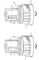
figure 1 représente en plan un système de distribution complet, selon l'invention, disposé à l'extrémité d'un tube, comportant une bande d'inviolabilité. - La
figure 2 représente en perspective un système de distribution complet, selon l'invention, disposé à l'extrémité d'un tube, comportant une bague de blocage. - La
figure 3 représente en perspective et à échelle agrandie l'élément de base du système, selon un premier exemple de réalisation par lamelle à débattement vertical, en position de fermeture. - La
figure 4 représente en perspective et à échelle agrandie l'élément de base du système, selon un premier exemple de réalisation par lamelle à débattement vertical, avant positionnement de celle-ci dans la fenêtre. - La
figure 5 représente en perspective et à échelle agrandie l'élément de base du système, selon un premier exemple de réalisation par lamelle à débattement horizontal, en position de fermeture. - La
figure 6 représente en perspective et à échelle agrandie l'élément de base du système, selon un premier exemple de réalisation par lamelle à débattement horizontal, avant positionnement de celle-ci dans la fenêtre. - La
figure 7 est une vue de dessus, en plan, d'un élément de base selon lafigure 6 . - La
figure 8 est une vue en perspective d'un capot coopérant avec un élément de base, selon les figures précédentes. - Les
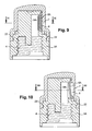
figures 9 et 10 sont des vues en coupe longitudinale, selon l'exemple de réalisation desfigures 3 et 4 , à lamelle verticale, respectivement en position de fermeture et d'ouverture. - Les
figures 11 et 12 sont respectivement des vues en coupe selon les lignes XI-XI et XII-XII desfigures 9 et 10 .
- The
figure 1 represents in plan a complete distribution system, according to the invention, disposed at the end of a tube, having a tamper-evident band. - The
figure 2 represents in perspective a complete distribution system, according to the invention, disposed at the end of a tube, comprising a locking ring. - The
figure 3 represents in perspective and on an enlarged scale the basic element of the system, according to a first embodiment of lamella with vertical displacement, in the closed position. - The
figure 4 represents in perspective and on an enlarged scale the basic element of the system, according to a first embodiment of vertical displacement lamella, before positioning it in the window. - The
figure 5 represents in perspective and on an enlarged scale the basic element of the system, according to a first embodiment of lamella with horizontal movement, in the closed position. - The
figure 6 represents in perspective and on an enlarged scale the basic element of the system, according to a first embodiment of lamella with horizontal displacement, before positioning it in the window. - The
figure 7 is a top view, in plan, of a base element according to thefigure 6 . - The
figure 8 is a perspective view of a cover cooperating with a base member, according to the preceding figures. - The
Figures 9 and 10 are views in longitudinal section, according to the embodiment of theFigures 3 and 4 , with vertical strip, respectively in the closed position and the open position. - The
Figures 11 and 12 are respectively sectional views along lines XI-XI and XII-XII ofFigures 9 and 10 .
Le système 1 globalement désigné sur les figures est destiné à être mis en place à l'extrémité ouverte d'un conditionnement 2, du type tube souple ou flacon, sur lequel on agit par pression manuelle pour provoquer l'évacuation d'un produit liquide ou pâteux, par l'intermédiaire de moyens d'ouverture-fermeture intégrés.The system 1 generally designated in the figures is intended to be put in place at the open end of a
Selon l'invention, il comprend un élément de base 3 formé par un corps creux fixé à l'extrémité ouverte 4 du tube 2 et comportant, sur sa périphérie ou son plan supérieur, une fenêtre 5A, 5B associée à une lamelle 6A, 6B, de forme et de dimensions sensiblement correspondantes, qui est mobile en ouverture sous l'effet d'une poussée du produit, lors d'une pression sur le tube 2, pour être rappelée automatiquement dans sa position initiale de fermeture lors de la cessation ou de la diminution de la pression.According to the invention, it comprises a
Cette lamelle est positionnée de manière à venir obturer la fenêtre située dans l'épaisseur de la base, de manière que la lamelle en position s'intègre et ne soit pas dépassante de l'épaisseur de l'élément de base. Lorsque la lamelle est dans sa fenêtre, elle obture complètement la fenêtre de manière étanche et empêche tout passage de produit.This slat is positioned to close the window located in the thickness of the base, so that the slat in position integrates and is not greater than the thickness of the base member. When the slat is in its window, it completely closes the window tightly and prevents any product passage.
Sous l'action d'une pression de l'utilisateur sur le tube, et donc du produit à l'intérieur du corps creux, la lamelle se déplace vers l'extérieur sous la pression.Under the action of a pressure of the user on the tube, and therefore the product inside the hollow body, the blade moves outward under pressure.
Le système comprend également un capot 7 destiné à coiffer l'élément de base 3A, 3B, au moins dans sa partie supérieure comportant la fenêtre 5A, 5B et la lamelle 6A, 6B, et comportant en regard de celles-ci un évidement interne 8, au moins de dimensions correspondantes à celles de la lamelle 6A, 6B et de profondeur telle à permettre le débattement en ouverture de celle-ci et conséquemment la réception du produit dudit évidement 8, puis son acheminement vers un trou de sortie 9 pratiqué dans une zone supérieure du capot 7, l'immobilisation en fermeture de la lamelle 6A, 6B étant obtenue par déplacement du capot 7, jusqu'à ce que l'évidement 8 ne soit plus en regard de celle-ci.The system also comprises a
C'est ainsi que la lamelle, par son positionnement dans le logement, permet de couper le flux de produit et empêcher un suintement de celui-ci non désiré, même lorsque l'évidement est en regard de la lamelle.Thus, the slat, by its positioning in the housing, allows to cut the flow of product and prevent unwanted oozing thereof, even when the recess is opposite the slat.
Selon un premier exemple de réalisation de la lamelle, représenté sur les
La lamelle tourne donc autour d'un axe de rotation, auquel cas la pression ne fait que soulever la lamelle, et celle-ci se repositionne lorsqu'un flux inverse est initié, ledit flux entraînant la lamelle.The blade thus rotates about an axis of rotation, in which case the pressure only raises the blade, and the blade is repositioned when an inverse flow is initiated, said flux driving the blade.
Selon une variante de réalisation non représentée, la fenêtre 5A de la base 3A étant rectangulaire, la lamelle mobile 6A l'occultant en fermeture est issue directement d'un côté droit supérieur 10 de ladite fenêtre, de manière à la rendre élastiquement déformable pour un débattement angulaire en ouverture, selon un plan vertical.According to an alternative embodiment not shown, the
Dans ce cas, il n'est pas nécessaire que l'évidement 8 du capot 7 soit réalisé sur toute la hauteur de la lamelle.In this case, it is not necessary that the
La lamelle est ici bloquée en rotation, auquel cas la lamelle se déforme élastiquement sous l'action de la pression et se repositionne automatiquement lors de la diminution de la pression.Here, the strip is locked in rotation, in which case the strip deforms elastically under the action of pressure and is automatically repositioned when the pressure is reduced.
Selon le second exemple de réalisation représenté sur les
Selon une variante non représentée du mode de réalisation qui vient d'être décrit, la fenêtre 5B de la base 3B étant rectangulaire, la lamelle mobile 6B l'occultant en fermeture est issue directement de l'un des côtés latéraux de ladite fenêtre 5B, de manière à la rendre élastiquement déformable pour un débattement angulaire en ouverture, selon un plan horizontal.According to a not shown variant of the embodiment which has just been described, the
Dans ce cas, comme précédemment, il n'est nullement besoin de réaliser l'évidement 8 du capot 7 sur tout la largeur de la lamelle 6B.In this case, as before, there is no need to make the
Selon une autre caractéristique de l'invention, l'élément de base 3A, 3B comporte une chambre de transit 12 du produit, réalisée à proximité de la fenêtre 5A, 5B avec laquelle elle communique par l'intermédiaire d'une chicane 13 ménagée sur une nervure séparative 14, chambre également en communication avec un trou de sortie 9 réalisé à la partie supérieur du capot 7, au droit de l'évidement interne 8 de celui-ci, dont la hauteur est sensiblement égale à celle de la fenêtre 5A, 5B et la largeur sensiblement égale à la somme de la largeur de la même fenêtre 5A, 5B et de la largeur de la chambre de transit 12.According to another characteristic of the invention, the
La chambre de transit 12 et la chicane 13 ont pour rôle essentiel d'obtenir une sortie du produit moins violente, car moins directe, du fait des pertes de charge.The
Il est à noter qu'on pourrait également prévoir de réaliser un trou de sortie du capot sur le côté de celui-ci plutôt que sur le dessus comme évoqué ci-dessus.It should be noted that it would also be possible to provide a hood exit hole on the side thereof rather than on the top as mentioned above.
Selon les exemples de réalisation représentés sur les figures, la position relative du capot 7, et plus particulièrement de son évidement interne 8, par rapport à l'élément de base 3, et plus particulièrement de la fenêtre 5A, 5B munie de la lamelle 6A, 6B et de la chambre de transit 12 attenante, est obtenue par rotation du capot 7 sur l'élément de base 3 pour l'obtention, soit d'une ouverture de la lamelle 6A, 6B et d'une sortie du produit par le trou 9 du capot 7, via l'évidement interne 8 du capot 7 et de la chambre de transit 12 de la base 3, lorsque ces parties sont en regard les unes des autres, soit d'une fermeture lorsqu'elles ne le sont pas.According to the exemplary embodiments shown in the figures, the relative position of the
Bien entendu, selon une autre variante de réalisation (non représentée) du moyen de fermeture, on pourrait imaginer un système « push-pull », c'est-à-dire non rotatif, mais selon un mouvement linéaire de bas en haut ou de haut en bas.Of course, according to another alternative embodiment (not shown) of the closure means, one could imagine a "push-pull" system, that is to say non-rotating, but in a linear movement from bottom to top or top to bottom.
Par ailleurs, le capot 7 et l'élément de base 3A, 3B comportent des moyens d'indexation complémentaires constitués respectivement par un doigt 15 issu de la périphérie externe d'une collerette inférieure 16 du capot 7, susceptible de se débattre en rotation dans une échancrure 17 correspondante, réalisée sur la périphérie externe d'une collerette supérieure 18 de l'élément de base 3, les positions maximum du doigt 15 dans l'échancrure 17 correspondant à une ouverture ou à une fermeture.Moreover, the
Selon une variante de réalisation, le capot 7 et l'élément de base 3A, 3B comportent des moyens d'indexation complémentaires constitués par des flèches disposées sur ledit capot et ledit élément de base, à mettre en regard l'une de l'autre, selon que l'on veuille obtenir une ouverture ou une fermeture du système.According to an alternative embodiment, the
L'élément de base 3A, 3B comporte, dans une zone centrale interne, un élément perforant 20 destiné au perçage d'un opercule du tube 2.The
Egalement, l'élément de base 3A, 3B comporte, sur sa périphérie inférieure, une bande d'inviolabilité 19 déchirable, en liaison avec le col 4 du tube 2.Also, the
Selon une variante de réalisation visible sur la
L'élément de base 3 pourra être vissé ou encliqueté sur le tube 2.The
En ce qui concerne le capot 7, celui-ci est clipé 22 sur l'élément de base.3.Regarding the
L'élément de base 3A, 3B, muni de son capot 7 qui lui est solidaire, sont protégés par un capuchon amovible 23.The
Enfin, qu'il s'agisse de l'élément de base 3, du capot 7 ou du capuchon 23, ces éléments constitutifs sont obtenus individuellement par moulage d'une matière plastique.Finally, whether it is the
L'invention concerne également un conditionnement, tube souple ou flacon, comportant un système de distribution tel que décrit ci-dessus.The invention also relates to a packaging, flexible tube or bottle, comprising a dispensing system as described above.
Claims (19)
- System (1) of delivering a liquid to pasty product, designed to be installed at the open end of a packaging element (2), of the flexible tube or small bottle type, on which the user acts by manual pressure to cause the product to come out via integrated opening/closing means, comprising:- a base element (3A, 3B) formed by a hollow body that is attached at the open end (4) of the tube (2) and comprises a window (5A, 5B) associated with a strip (6A, 6B), of substantially matching shape and dimensions, that can be moved in opening under the effect of pressure of the product, during a pressing action on the tube (2), to be returned automatically to its initial closed position when the pressure ceases or diminishes,- and characterized in that it comprises a cap (7) designed to cover the base element (3A, 3B) at least in its top part comprising the window (5A, 5B) and the strip (6A, 6B), and comprising an internal recess (8) opposite the latter, of dimensions at least matching those of the strip (6A, 6B) and of such a depth as to allow the deflection in opening of the latter and consequently the receipt of the product from said recess (8), then its routing toward an outlet hole (9) made in a top zone of the cap (7).
- Delivery system according to Claim 1, characterized in that the window (5A, 5B) associated with the strip (6A, 6B) is made on the periphery of the hollow body of the base element (3A, 3B) .
- Delivery system according to Claim 1, characterized in that the window (5A, 5B) associated with the strip (6A, 6B) is made on the top plane of the hollow body of the base element (3A, 3B) .
- Delivery system according to one of Claims 1 to 3, characterized in that the strip (6A, 6B) is locked in closure by moving the cap (7) until the recess (8) is no longer opposite the latter.
- Delivery system according to one of Claims 1 to 4, characterized in that, the window (5A) of the base (3A) being rectangular, the movable strip (6A) blocking it off in closure is fixedly attached to a top right side (10) of said window (5A) by means of an articulation, the recess (8) of the cap (7) being made over the whole height of the strip (6A) in order to allow the angular deflection in opening of the latter, along a vertical plane.
- Delivery system according to one of Claims 1 to 4, characterized in that, the window (5A) of the base (3A) being rectangular, the movable strip (6A) blocking it off in closure originates directly from a top right side (10) of said window, in order to render it elastically deformable for an angular deflection in opening, along a vertical plane.
- Delivery system according to one of Claims 1 to 4, characterized in that, the window (5B) of the base (3B) being rectangular, the movable strip (6B) blocking it off in closure is fixedly attached to one of the lateral sides (11) of said window (5B) by means of an articulation, the recess (8) of the cap (7) being made over the whole width of the strip (6B) in order to allow the angular deflection of the strip (6B) in opening, along a horizontal plane.
- Delivery system according to one of Claims 1 to 4, characterized in that, the window (5B) of the base (3B) being rectangular, the movable strip (6B) blocking it off in closure originates directly from one of the lateral sides of said window (5B), in order to render it elastically deformable for an angular deflection in opening, along a horizontal plane.
- Delivery system according to one of the preceding claims, characterized in that the base element (3A, 3B) comprises a transit chamber (12) for the product, made close to the window (5A, 5B) with which it communicates via a chicane (13) made on a separating rib (14), a chamber also in communication with an outlet hole (9) made on the top part of the cap (7), in line with the internal recess (8) of the latter, whose height is substantially equal to that of the window (5A, 5B) and whose width substantially equal to the sum of the width of the same window (5A, 5B) and the width of the transit chamber (12).
- Delivery system according to Claim 9, characterized in that the cap (7) and the base element (3A, 3B) comprise matching indexation means consisting respectively of a finger (15) originating from the outer periphery of a bottom collar (16) of the cap (7), capable of deflecting in rotation into a matching indentation (17), made on the outer periphery of a top collar (18) of the base element (3), the maximum positions of the finger (15) in the indentation (17) corresponding to an opening or a closure.
- Delivery system according to Claim 9, characterized in that the cap (7) and the base element (3A, 3B) comprise matching indexation means consisting of arrows placed on said cap and said base element, to be placed opposite one another, depending on whether the user wishes to obtain an opening or a closure of the system.
- Delivery system according to one of the preceding claims, characterized in that the base element (3A, 3B) comprises, in an inner central zone, a perforating element (20) designed to pierce a lid of the tube (2).
- Delivery system according to one of the preceding claims, characterized in that the base element (3A, 3B) comprises, on its bottom periphery, a tear-off anti-tamper band (19) connected with the neck (4) of the tube (2).
- Delivery system according to one of Claims 1 to 12, characterized in that a locking ring (21) is interposed between the base element (3A, 3B) and the tube (2) in order to prevent any attempt at piercing by screwing.
- Delivery system according to one of the preceding claims, characterized in that the base element (3A, 3B) is screwed onto the tube (2).
- Delivery system according to one of Claims 1 to 14, characterized in that the base element (3A, 3B) is snapped onto the tube (2).
- Delivery system according to one of the preceding claims, characterized in that the cap (7) is clipped (22) onto the base element (3A, 3B).
- Delivery system according to one of the preceding claims, characterized in that the base element (3A, 3B), furnished with its cap (7) which is fixedly attached thereto, is protected by a removable top (23).
- Packaging element, characterized in that it comprises an anti-seepage delivery system according to one of the preceding claims.
Applications Claiming Priority (3)
| Application Number | Priority Date | Filing Date | Title |
|---|---|---|---|
| FR0604004A FR2900393B1 (en) | 2006-04-26 | 2006-04-26 | ANTI-SUINTEMENT DISTRIBUTION SYSTEM OF A CONDITIONED PRODUCT, AND PACKAGING COMPRISING IT. |
| FR0604505A FR2900394B1 (en) | 2006-04-26 | 2006-05-19 | ANTI-SUINTEMENT DISTRIBUTION SYSTEM OF A CONDITIONED PRODUCT, AND PACKAGING COMPRISING THE SAME |
| PCT/FR2007/000343 WO2007128889A1 (en) | 2006-04-26 | 2007-02-26 | Anti-oozing packaged product dispensing system, and packaging comprising same |
Publications (2)
| Publication Number | Publication Date |
|---|---|
| EP2013101A1 EP2013101A1 (en) | 2009-01-14 |
| EP2013101B1 true EP2013101B1 (en) | 2009-11-11 |
Family
ID=38293154
Family Applications (1)
| Application Number | Title | Priority Date | Filing Date |
|---|---|---|---|
| EP07731047A Not-in-force EP2013101B1 (en) | 2006-04-26 | 2007-02-26 | Anti-oozing product dispensing system, and packaging comprising same |
Country Status (8)
| Country | Link |
|---|---|
| US (1) | US7568597B2 (en) |
| EP (1) | EP2013101B1 (en) |
| AT (1) | ATE448154T1 (en) |
| CA (1) | CA2650078A1 (en) |
| DE (1) | DE602007003214D1 (en) |
| ES (1) | ES2334468T3 (en) |
| FR (1) | FR2900394B1 (en) |
| WO (1) | WO2007128889A1 (en) |
Families Citing this family (1)
| Publication number | Priority date | Publication date | Assignee | Title |
|---|---|---|---|---|
| US10864923B2 (en) | 2017-06-06 | 2020-12-15 | Kelly J. Deason | Single pole aerial tramway apparatus for cycles |
Family Cites Families (9)
| Publication number | Priority date | Publication date | Assignee | Title |
|---|---|---|---|---|
| US2143661A (en) * | 1938-02-23 | 1939-01-10 | Arthur W Schrader | Dispensing head for collapsible tubes |
| FR967181A (en) * | 1948-06-01 | 1950-10-27 | Cap with automatic opening and closing for all tubes containing pasty semi-liquid or liquid products | |
| US2750084A (en) * | 1952-09-11 | 1956-06-12 | James G Moran | Liquid and semi-liquid dispensing containers |
| US3200995A (en) * | 1962-08-30 | 1965-08-17 | Colgate Palmolive Co | Multicompartment dispensing package |
| US3876118A (en) * | 1973-08-10 | 1975-04-08 | Adolfo Arias Loredo | Dispensing container closure |
| FR2660877B1 (en) * | 1990-04-13 | 1992-07-31 | Oreal | DISPENSING ASSEMBLY OF AT LEAST ONE LIQUID OR CREAM PRODUCT. |
| US6398077B1 (en) * | 2000-02-11 | 2002-06-04 | Seaquist Closures Foreign, Inc. | Package with multiple chambers and valves |
| JP4039507B2 (en) * | 2000-02-25 | 2008-01-30 | 株式会社吉野工業所 | Tube container |
| FR2833579B1 (en) * | 2001-12-13 | 2004-10-08 | Plastohm Sa | STERILE DISPENSING SYSTEM FOR A PRODUCT CONTAINED IN A CONTAINER, IN PARTICULAR A FLEXIBLE TUBE |
-
2006
- 2006-05-19 FR FR0604505A patent/FR2900394B1/en not_active Expired - Fee Related
- 2006-05-24 US US11/440,684 patent/US7568597B2/en not_active Expired - Fee Related
-
2007
- 2007-02-26 WO PCT/FR2007/000343 patent/WO2007128889A1/en active Application Filing
- 2007-02-26 EP EP07731047A patent/EP2013101B1/en not_active Not-in-force
- 2007-02-26 ES ES07731047T patent/ES2334468T3/en active Active
- 2007-02-26 AT AT07731047T patent/ATE448154T1/en not_active IP Right Cessation
- 2007-02-26 CA CA002650078A patent/CA2650078A1/en not_active Abandoned
- 2007-02-26 DE DE602007003214T patent/DE602007003214D1/en active Active
Also Published As
| Publication number | Publication date |
|---|---|
| EP2013101A1 (en) | 2009-01-14 |
| ES2334468T3 (en) | 2010-03-10 |
| US7568597B2 (en) | 2009-08-04 |
| FR2900394A1 (en) | 2007-11-02 |
| WO2007128889A1 (en) | 2007-11-15 |
| CA2650078A1 (en) | 2007-11-15 |
| FR2900394B1 (en) | 2008-06-27 |
| ATE448154T1 (en) | 2009-11-15 |
| US20070251958A1 (en) | 2007-11-01 |
| DE602007003214D1 (en) | 2009-12-24 |
Similar Documents
| Publication | Publication Date | Title |
|---|---|---|
| EP0540129B1 (en) | Assembly for dispensing a fluid product such as cosmetics or pharmaceutics | |
| CA2172229C (en) | Liquid or paste product dispenser, particularly for cosmetic preparations | |
| EP0538094B1 (en) | Metal container which can be partially opened by tearing along a line of weakness | |
| EP2326560B1 (en) | Package provided with a leaktight opening and closing device | |
| EP1633646B1 (en) | Closure having an unlockable lid with elastic return | |
| EP0761558B1 (en) | Device for closing a container and dispensing the product contained in it | |
| FR2887498A1 (en) | HEAD FOR FUEL FILLING TUBE OF A VEHICLE | |
| EP0819614A1 (en) | Opening and closing device for a package, and package with such a device | |
| CA2231168A1 (en) | Spout with stopper for containers, particularly for liquid packaging boxes | |
| EP3417948B1 (en) | Moulded pump for dispensing a fluid product | |
| EP1651540B1 (en) | Fluid product dispensing head | |
| EP2013101B1 (en) | Anti-oozing product dispensing system, and packaging comprising same | |
| FR2780385A1 (en) | Metal cover for a drinks bottle | |
| WO2004058588A1 (en) | Sealing device for a container opening | |
| EP3980350B1 (en) | Valve for pressurised container | |
| FR2900393A1 (en) | Liquid delivering system for use in packaging element, has strip locked in closure by moving cap until recess is no longer opposite to cap, where cap is clipped onto base element, and base element furnished with cap | |
| EP1770022B1 (en) | Closure | |
| FR2981337A1 (en) | FLUID PRODUCT DISPENSER. | |
| EP2065315B1 (en) | Single-part lowered sealing cap including a drip stop | |
| FR2711360A1 (en) | Closure device for a container provided with a neck, of the bottle or pot type. | |
| EP1405796A1 (en) | Fluid dispensing apparatus | |
| FR2791036A1 (en) | Container for freezing or reheating foodstuffs has container with sealed lid and tabs to allow controlled ingress of air | |
| EP2731888B1 (en) | Stopper element and dispenser comprising such an element | |
| EP1919790B1 (en) | Container comprising a screw-on/screw-off locking cover | |
| EP3437512B1 (en) | Packaging for cosmetic product |
Legal Events
| Date | Code | Title | Description |
|---|---|---|---|
| PUAI | Public reference made under article 153(3) epc to a published international application that has entered the european phase |
Free format text: ORIGINAL CODE: 0009012 |
|
| 17P | Request for examination filed |
Effective date: 20081006 |
|
| AK | Designated contracting states |
Kind code of ref document: A1 Designated state(s): AT BE BG CH CY CZ DE DK EE ES FI FR GB GR HU IE IS IT LI LT LU LV MC NL PL PT RO SE SI SK TR |
|
| AX | Request for extension of the european patent |
Extension state: AL BA HR MK RS |
|
| GRAP | Despatch of communication of intention to grant a patent |
Free format text: ORIGINAL CODE: EPIDOSNIGR1 |
|
| RTI1 | Title (correction) |
Free format text: ANTI-OOZING PRODUCT DISPENSING SYSTEM, AND PACKAGING COMPRISING SAME |
|
| DAX | Request for extension of the european patent (deleted) | ||
| GRAS | Grant fee paid |
Free format text: ORIGINAL CODE: EPIDOSNIGR3 |
|
| GRAA | (expected) grant |
Free format text: ORIGINAL CODE: 0009210 |
|
| AK | Designated contracting states |
Kind code of ref document: B1 Designated state(s): AT BE BG CH CY CZ DE DK EE ES FI FR GB GR HU IE IS IT LI LT LU LV MC NL PL PT RO SE SI SK TR |
|
| REG | Reference to a national code |
Ref country code: GB Ref legal event code: FG4D Free format text: NOT ENGLISH |
|
| REG | Reference to a national code |
Ref country code: CH Ref legal event code: EP |
|
| RIN2 | Information on inventor provided after grant (corrected) |
Inventor name: LEMERLE, JEAN-CHRISTOPHE Inventor name: BROGLY, SEBASTIEN Inventor name: LAUTRE, PHILIPPE |
|
| REG | Reference to a national code |
Ref country code: CH Ref legal event code: NV Representative=s name: WILLIAM BLANC & CIE CONSEILS EN PROPRIETE INDUSTRI |
|
| REG | Reference to a national code |
Ref country code: IE Ref legal event code: FG4D |
|
| RAP2 | Party data changed (patent owner data changed or rights of a patent transferred) |
Owner name: PROMENS SA |
|
| REF | Corresponds to: |
Ref document number: 602007003214 Country of ref document: DE Date of ref document: 20091224 Kind code of ref document: P |
|
| NLT2 | Nl: modifications (of names), taken from the european patent patent bulletin |
Owner name: PROMENS SA Effective date: 20091216 |
|
| REG | Reference to a national code |
Ref country code: ES Ref legal event code: FG2A Ref document number: 2334468 Country of ref document: ES Kind code of ref document: T3 |
|
| NLV1 | Nl: lapsed or annulled due to failure to fulfill the requirements of art. 29p and 29m of the patents act | ||
| LTIE | Lt: invalidation of european patent or patent extension |
Effective date: 20091111 |
|
| PG25 | Lapsed in a contracting state [announced via postgrant information from national office to epo] |
Ref country code: IS Free format text: LAPSE BECAUSE OF FAILURE TO SUBMIT A TRANSLATION OF THE DESCRIPTION OR TO PAY THE FEE WITHIN THE PRESCRIBED TIME-LIMIT Effective date: 20100311 Ref country code: FI Free format text: LAPSE BECAUSE OF FAILURE TO SUBMIT A TRANSLATION OF THE DESCRIPTION OR TO PAY THE FEE WITHIN THE PRESCRIBED TIME-LIMIT Effective date: 20091111 Ref country code: LT Free format text: LAPSE BECAUSE OF FAILURE TO SUBMIT A TRANSLATION OF THE DESCRIPTION OR TO PAY THE FEE WITHIN THE PRESCRIBED TIME-LIMIT Effective date: 20091111 Ref country code: PT Free format text: LAPSE BECAUSE OF FAILURE TO SUBMIT A TRANSLATION OF THE DESCRIPTION OR TO PAY THE FEE WITHIN THE PRESCRIBED TIME-LIMIT Effective date: 20100311 Ref country code: SE Free format text: LAPSE BECAUSE OF FAILURE TO SUBMIT A TRANSLATION OF THE DESCRIPTION OR TO PAY THE FEE WITHIN THE PRESCRIBED TIME-LIMIT Effective date: 20091111 |
|
| PG25 | Lapsed in a contracting state [announced via postgrant information from national office to epo] |
Ref country code: PL Free format text: LAPSE BECAUSE OF FAILURE TO SUBMIT A TRANSLATION OF THE DESCRIPTION OR TO PAY THE FEE WITHIN THE PRESCRIBED TIME-LIMIT Effective date: 20091111 Ref country code: CY Free format text: LAPSE BECAUSE OF FAILURE TO SUBMIT A TRANSLATION OF THE DESCRIPTION OR TO PAY THE FEE WITHIN THE PRESCRIBED TIME-LIMIT Effective date: 20091111 Ref country code: LV Free format text: LAPSE BECAUSE OF FAILURE TO SUBMIT A TRANSLATION OF THE DESCRIPTION OR TO PAY THE FEE WITHIN THE PRESCRIBED TIME-LIMIT Effective date: 20091111 Ref country code: SI Free format text: LAPSE BECAUSE OF FAILURE TO SUBMIT A TRANSLATION OF THE DESCRIPTION OR TO PAY THE FEE WITHIN THE PRESCRIBED TIME-LIMIT Effective date: 20091111 |
|
| REG | Reference to a national code |
Ref country code: IE Ref legal event code: FD4D |
|
| PG25 | Lapsed in a contracting state [announced via postgrant information from national office to epo] |
Ref country code: AT Free format text: LAPSE BECAUSE OF FAILURE TO SUBMIT A TRANSLATION OF THE DESCRIPTION OR TO PAY THE FEE WITHIN THE PRESCRIBED TIME-LIMIT Effective date: 20091111 |
|
| REG | Reference to a national code |
Ref country code: CH Ref legal event code: PFA Owner name: PROMENS SA Free format text: PROMENS SA#RUE DE GRANGE MARTIN#69656 ZI NORD (FR) -TRANSFER TO- PROMENS SA#RUE DE GRANGE MARTIN#69656 ZI NORD (FR) |
|
| PG25 | Lapsed in a contracting state [announced via postgrant information from national office to epo] |
Ref country code: DK Free format text: LAPSE BECAUSE OF FAILURE TO SUBMIT A TRANSLATION OF THE DESCRIPTION OR TO PAY THE FEE WITHIN THE PRESCRIBED TIME-LIMIT Effective date: 20091111 Ref country code: EE Free format text: LAPSE BECAUSE OF FAILURE TO SUBMIT A TRANSLATION OF THE DESCRIPTION OR TO PAY THE FEE WITHIN THE PRESCRIBED TIME-LIMIT Effective date: 20091111 Ref country code: IE Free format text: LAPSE BECAUSE OF FAILURE TO SUBMIT A TRANSLATION OF THE DESCRIPTION OR TO PAY THE FEE WITHIN THE PRESCRIBED TIME-LIMIT Effective date: 20091111 Ref country code: BG Free format text: LAPSE BECAUSE OF FAILURE TO SUBMIT A TRANSLATION OF THE DESCRIPTION OR TO PAY THE FEE WITHIN THE PRESCRIBED TIME-LIMIT Effective date: 20100211 Ref country code: RO Free format text: LAPSE BECAUSE OF FAILURE TO SUBMIT A TRANSLATION OF THE DESCRIPTION OR TO PAY THE FEE WITHIN THE PRESCRIBED TIME-LIMIT Effective date: 20091111 |
|
| BERE | Be: lapsed |
Owner name: PLASTOHM S.A. Effective date: 20100228 |
|
| PG25 | Lapsed in a contracting state [announced via postgrant information from national office to epo] |
Ref country code: CZ Free format text: LAPSE BECAUSE OF FAILURE TO SUBMIT A TRANSLATION OF THE DESCRIPTION OR TO PAY THE FEE WITHIN THE PRESCRIBED TIME-LIMIT Effective date: 20091111 Ref country code: SK Free format text: LAPSE BECAUSE OF FAILURE TO SUBMIT A TRANSLATION OF THE DESCRIPTION OR TO PAY THE FEE WITHIN THE PRESCRIBED TIME-LIMIT Effective date: 20091111 |
|
| PLBE | No opposition filed within time limit |
Free format text: ORIGINAL CODE: 0009261 |
|
| STAA | Information on the status of an ep patent application or granted ep patent |
Free format text: STATUS: NO OPPOSITION FILED WITHIN TIME LIMIT |
|
| 26N | No opposition filed |
Effective date: 20100812 |
|
| PG25 | Lapsed in a contracting state [announced via postgrant information from national office to epo] |
Ref country code: GR Free format text: LAPSE BECAUSE OF FAILURE TO SUBMIT A TRANSLATION OF THE DESCRIPTION OR TO PAY THE FEE WITHIN THE PRESCRIBED TIME-LIMIT Effective date: 20100212 Ref country code: MC Free format text: LAPSE BECAUSE OF NON-PAYMENT OF DUE FEES Effective date: 20100301 |
|
| PG25 | Lapsed in a contracting state [announced via postgrant information from national office to epo] |
Ref country code: BE Free format text: LAPSE BECAUSE OF NON-PAYMENT OF DUE FEES Effective date: 20100228 |
|
| PGFP | Annual fee paid to national office [announced via postgrant information from national office to epo] |
Ref country code: FR Payment date: 20110302 Year of fee payment: 5 Ref country code: DE Payment date: 20110223 Year of fee payment: 5 Ref country code: IT Payment date: 20110219 Year of fee payment: 5 Ref country code: CH Payment date: 20110214 Year of fee payment: 5 |
|
| PGRI | Patent reinstated in contracting state [announced from national office to epo] |
Ref country code: IT Effective date: 20110501 |
|
| REG | Reference to a national code |
Ref country code: CH Ref legal event code: PCAR Free format text: NOVAGRAAF SWITZERLAND SA;CHEMIN DE L'ECHO 3;1213 ONEX (CH) |
|
| PGFP | Annual fee paid to national office [announced via postgrant information from national office to epo] |
Ref country code: ES Payment date: 20110315 Year of fee payment: 5 Ref country code: GB Payment date: 20110223 Year of fee payment: 5 |
|
| PGRI | Patent reinstated in contracting state [announced from national office to epo] |
Ref country code: IT Effective date: 20110501 |
|
| PG25 | Lapsed in a contracting state [announced via postgrant information from national office to epo] |
Ref country code: NL Free format text: LAPSE BECAUSE OF FAILURE TO SUBMIT A TRANSLATION OF THE DESCRIPTION OR TO PAY THE FEE WITHIN THE PRESCRIBED TIME-LIMIT Effective date: 20091111 Ref country code: HU Free format text: LAPSE BECAUSE OF FAILURE TO SUBMIT A TRANSLATION OF THE DESCRIPTION OR TO PAY THE FEE WITHIN THE PRESCRIBED TIME-LIMIT Effective date: 20100512 Ref country code: LU Free format text: LAPSE BECAUSE OF NON-PAYMENT OF DUE FEES Effective date: 20100226 |
|
| REG | Reference to a national code |
Ref country code: CH Ref legal event code: PL |
|
| GBPC | Gb: european patent ceased through non-payment of renewal fee |
Effective date: 20120226 |
|
| PG25 | Lapsed in a contracting state [announced via postgrant information from national office to epo] |
Ref country code: LI Free format text: LAPSE BECAUSE OF NON-PAYMENT OF DUE FEES Effective date: 20120229 Ref country code: CH Free format text: LAPSE BECAUSE OF NON-PAYMENT OF DUE FEES Effective date: 20120229 Ref country code: TR Free format text: LAPSE BECAUSE OF FAILURE TO SUBMIT A TRANSLATION OF THE DESCRIPTION OR TO PAY THE FEE WITHIN THE PRESCRIBED TIME-LIMIT Effective date: 20091111 |
|
| REG | Reference to a national code |
Ref country code: FR Ref legal event code: ST Effective date: 20121031 |
|
| PG25 | Lapsed in a contracting state [announced via postgrant information from national office to epo] |
Ref country code: IT Free format text: LAPSE BECAUSE OF NON-PAYMENT OF DUE FEES Effective date: 20120226 |
|
| REG | Reference to a national code |
Ref country code: DE Ref legal event code: R119 Ref document number: 602007003214 Country of ref document: DE Effective date: 20120901 |
|
| PG25 | Lapsed in a contracting state [announced via postgrant information from national office to epo] |
Ref country code: FR Free format text: LAPSE BECAUSE OF NON-PAYMENT OF DUE FEES Effective date: 20120229 Ref country code: GB Free format text: LAPSE BECAUSE OF NON-PAYMENT OF DUE FEES Effective date: 20120226 |
|
| PG25 | Lapsed in a contracting state [announced via postgrant information from national office to epo] |
Ref country code: DE Free format text: LAPSE BECAUSE OF NON-PAYMENT OF DUE FEES Effective date: 20120901 |
|
| REG | Reference to a national code |
Ref country code: ES Ref legal event code: FD2A Effective date: 20131022 |
|
| PG25 | Lapsed in a contracting state [announced via postgrant information from national office to epo] |
Ref country code: ES Free format text: LAPSE BECAUSE OF NON-PAYMENT OF DUE FEES Effective date: 20120227 |