EP2012973B1 - Reconfigurable low-profile pneumatic edge-clamp systems and methods - Google Patents
Reconfigurable low-profile pneumatic edge-clamp systems and methods Download PDFInfo
- Publication number
- EP2012973B1 EP2012973B1 EP07755688.4A EP07755688A EP2012973B1 EP 2012973 B1 EP2012973 B1 EP 2012973B1 EP 07755688 A EP07755688 A EP 07755688A EP 2012973 B1 EP2012973 B1 EP 2012973B1
- Authority
- EP
- European Patent Office
- Prior art keywords
- clamping
- elongated
- workpiece
- beam member
- cavity
- Prior art date
- Legal status (The legal status is an assumption and is not a legal conclusion. Google has not performed a legal analysis and makes no representation as to the accuracy of the status listed.)
- Active
Links
Images


Classifications
-
- B—PERFORMING OPERATIONS; TRANSPORTING
- B25—HAND TOOLS; PORTABLE POWER-DRIVEN TOOLS; MANIPULATORS
- B25B—TOOLS OR BENCH DEVICES NOT OTHERWISE PROVIDED FOR, FOR FASTENING, CONNECTING, DISENGAGING, OR HOLDING
- B25B5/00—Clamps
- B25B5/06—Arrangements for positively actuating jaws
- B25B5/061—Arrangements for positively actuating jaws with fluid drive
- B25B5/065—Arrangements for positively actuating jaws with fluid drive involving the use of flexible pressure bags or diaphragms
-
- B—PERFORMING OPERATIONS; TRANSPORTING
- B25—HAND TOOLS; PORTABLE POWER-DRIVEN TOOLS; MANIPULATORS
- B25B—TOOLS OR BENCH DEVICES NOT OTHERWISE PROVIDED FOR, FOR FASTENING, CONNECTING, DISENGAGING, OR HOLDING
- B25B5/00—Clamps
- B25B5/003—Combinations of clamps
Definitions
- This invention relates to systems and methods for securing a workpiece during a manufacturing operation, and more specifically, to pneumatic edge-clamp systems and methods that may be used, for example, in welding or other manufacturing operations.
- a sheet aluminum panel is clamped against an aluminum substructure, such as an I-beam, to allow a high speed rotating spindle to engage the panel, causing friction-induced elevated temperatures which fuse the panel and substructure together.
- an aluminum substructure such as an I-beam
- One proven method of clamping the aluminum panel is to use commercially available pneumatic inflatable bladders which expand against the panel to restrain movement of the panel and press it firmly against the substructure.
- inflatable flexible bladders are typically contained in a low profile metal frame that is machined with an offset contour that matches the panel. The offset contour places the inflatable bladder slightly offset above the panel, allowing the flexible bladder to expand against and conform to the surface contour of the panel.
- a set of these metal frames can be placed nearby both sides of the friction stir welded joint to provide secure clamping on each side of the rotating spindle.
- DE19816014A concerns a fastening arrangement for joining sheet metal car body components.
- An inflatable hose member is employed to apply a force via compression elements to workpieces in order to clamp them together.
- the present invention provides pneumatic edge-clamp systems and methods for securing a workpiece during a manufacturing operation.
- Embodiments of the present invention may advantageously provide a low-profile edge-clamping system that operates with a short displacement, conforms to the surface contour of the panel, provides quick actuation, and that is readily reconfigurable as needed.
- a clamping apparatus for applying a clamping force to a workpiece includes a beam member having a cavity disposed therein, and an inflatable member disposed within the cavity.
- the inflatable member is coupleable to a pressurization source.
- a clamping member is pivotably coupled to the beam member.
- the clamping member includes a first portion projecting at least partially over the cavity, and a second portion projecting laterally outwardly from the beam member over the workpiece. In operation, inflating the inflatable member applies a driving force to the first portion, rotating the clamping member, and applying a clamping force to the workpiece using the second portion.
- the present invention relates to pneumatic edge-clamp systems and methods for securing a workpiece during a manufacturing operation.
- Many specific details of certain embodiments of the invention are set forth in the following description and in FIGURES 1 through 8 to provide a thorough understanding of such embodiments.
- One skilled in the art, however, will understand that the present invention may have additional embodiments, or that the present invention may be practiced without several of the details described in the following description.
- FIGURE 1 illustrates a manufacturing system 18 in accordance with an embodiment of the present invention.
- the manufacturing system 18 includes a controller 20, a pneumatic pump 19, and a clamping device 21.
- the controller 20 controls operation of the pneumatic pump 19 for supplying pressurized air to various components of the clamping device 21.
- the controller 20 may also control other components of the manufacturing system 18, including one or more tools 30 that perform manufacturing operations on one or more workpieces secured by the clamping device 21.
- the tools 30 are welding components, such as friction stir welding heads or the like.
- the clamping device 21 includes one or more edge-clamp systems 26 and one or more pneumatic surface clamps 32 for securely positioning a first workpiece 24 with respect to a second workpiece 22 during the performance of the manufacturing operation (e.g. welding).
- the pneumatic surface clamps 32 and the edge-clamps systems 26 are attached to one or more fixture bases 28.
- the tools 30 may perform welding (e.g. friction stir welding) along pre-defined paths to securely bond the first and second workpieces 24, 22 together. In alternate embodiments, any other desired manufacturing operations may be performed.
- FIGURE 2 illustrates a cross-sectional view of a portion of the manufacturing system 18 of FIGURE 1 .
- the pneumatic surface clamp 32 includes an inflatable seal 52 that, when inflated by the pump 19, applies pressure on the first workpiece 24, securely engaging the first workpiece 24 against the second workpiece 22.
- the first workpiece 24 is a molded aluminum skin, such as that of a fuselage of an aircraft
- the second workpiece 22 is an aluminum stringer or beam suitable for use within an airframe.
- the structure and operation of the surface clamp 52 is described more fully, for example, in co-pending, commonly owned U.S. Patent Application No.
- the edge-clamp system 26 includes an edge-clamp device 56 operatively coupled to a beam 58.
- the edge-clamp-device 56 includes a clamp bar 62 rotatably attached to a retainer block 64 by a pivot pin 68.
- a securing bolt 66 attaches the retainer block 64 to the beam 58.
- the beam 58 includes an approximately U-shaped cavity 78 for receiving an inflatable bladder (or seal) 60, and a plurality of threaded holes 80 ( FIGURE 3 ) for receiving the securing bolt 66.
- the inflatable seal 60 applies pressure on a first portion of the clamp bar 62, rotating the clamp bar 62 about the pivot pin 68 and forcing a second portion of the clamp bar 62 downwardly to apply a clamping force F c on the first workpiece 24.
- the edge-clamp system 26 thereby securely engages the first workpiece 24 against the second workpiece 22 during a manufacturing operation.
- the tool 30 is placed between the edge-clamp system 26 and the surface clamp 34 in order to get the tool 30 as close as possible to a common edge of the first and second workpieces 22, 24.
- the U-shaped cavity 78 extends from a first end 86a of the beam 58 to a second end 86b of the beam 58.
- the inflatable seal 60 is received within the cavity 78 and includes a stem 76 that passes through an opening in the cavity 78.
- the stem 76 is coupled to the pump 19.
- the inflatable seal 60 may be attached to the base of the cavity 78 using, for example, a suitable adhesive.
- the inflatable seal 60 is a Presray Pneuma-seal ® commercially-available from the Pawling Corporation of Pawling, New York.
- each end 86a and 86b of the beam 58 includes through holes 87 for receiving the bolts 36 that secure the beam 58 onto the respective fixture bases 28.
- each end 86a, 86b of the beam 58 includes a pair of threaded members 84 to secure the beam 58 to the bases 28 and to prevent movement of the beam 58 during a clamping process.
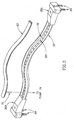
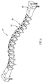
- FIGURE 4 illustrates a perspective view of the edge-clamp system 26 of FIGURE 1 .
- a plurality of edge-clamp devices 56 are coupled to the beam 58
- a plurality of seal restriction members 90 are coupled to the beam 58 and interspersed between the edge-clamp devices 56.
- the securing bolt 66 is threaded through the retainer block 64 and received by one of the threaded holes 80 in the beam 58.
- edge-clamp devices 56 are evenly distributed along the beam 58, however, in alternate embodiments, the edge-clamp devices 56 (and seal restriction members 90) may be non-uniformly distributed along the beam at desired locations depending upon the requirements of the manufacturing operation. In further embodiments, a greater or lesser number of edge-clamp devices 56 (and seal restriction members 90) may be employed than are shown in FIGURE 4 .
- FIGURE 6 is an enlarged partially-exploded view of a portion of the edge-clamp device 26 of FIGURE 4 .
- the seal restriction member 90 is coupled to the beam 58 by a bolt 92 that passes through a hole in the seal restriction member 90 and is received by one of the threaded holes 80.
- the seal restriction members 90 may be coupled to the beam 58 using any suitable attachment device, or alternately, may be integrally-formed with the beam 58.
- the seal restriction member 90 when attached to the beam 58, is configured to extend at least partially over the U-shaped cavity 78 of the beam 58, thereby restricting expansion of the inflatable seal 60 between the edge-clamp devices 56.
- the seal restriction member 90 includes a first portion 91 that contacts the beam 58, and a second portion 93 that extends over the inflatable seal 60 disposed within the U-shaped cavity 78.
- the first portion 91 may have a greater thickness than the second portion 93.
- the thicknesses of the first and second portions 91, 93 may be selected to allow the inflatable seal 60 to expand a pre-defined amount that would in turn allow the clamp bar 62 of the edge-clamp device 56 to rotate a pre-set amount, thereby putting proper pressure on the first workpiece 24.
- FIGURE 7 shows an enlarged cross-sectional view of a portion of the edge clamp system 26 of FIGURE 4 .
- the clamp bar 62 includes a non-abrasive tip 90 that engages the first workpiece 24 during the clamping operation.
- the non-abrasive tip 90 is a polymer tip that reduces marring or scratching of the first workpiece 24 and reduces thermal conduction from the first workpiece 24 into the clamp bar 62 during manufacturing operations ( e . g . welding).
- the tip 90 is attached to the clamp bar 62 by an attachment pin 92.
- the tip 90 may be adhesively attached, or attached by any other suitable means to the clamp bar 62.
- FIGURE 8 illustrates the rotational movement of the clamp bar 62 about the pivot pin 68 as the inflatable seal 60 is being pressurized. More specifically, as the inflatable seal 60 is pressurized, a driving force F d is applied by the inflatable seal 60 against the first end 62a of the clamp bar 62, thus forcing the clamp bar 62 to rotate (generally depicted as arrow R) about the pivot pin 68. In turn, the second end 62b of the clamp bar 62 is forced downwardly, causing the tip 90 to apply the clamping force Fc onto the first workpiece 24. The clamping force Fc is maintained on the first workpiece 24 until the seal 60 is deflated.
- a driving force F d is applied by the inflatable seal 60 against the first end 62a of the clamp bar 62, thus forcing the clamp bar 62 to rotate (generally depicted as arrow R) about the pivot pin 68.
- the second end 62b of the clamp bar 62 is forced downwardly, causing the tip 90 to apply the clamping force Fc onto
- Embodiments of the present invention may provide significant advantages over the prior art.
- embodiments of edge-clamp systems 26 may allow an edge of a workpiece to be secured using less surface area of the workpiece than alternate clamping systems ⁇ e.g. pneumatic surface clamp 32), thereby allowing room for the tool 30 while properly securing the workpiece during the performance of manufacturing operations near the edge.
- embodiments of the invention may provide a low-profile edge-clamping system that operates with a short displacement, thereby performing the desired clamping function without interfering with the performance of the manufacturing operations.
- embodiments of the invention may advantageously be configured to conform to a variety of surface contours, and may be readily reconfigurable by adjustment of the locations of the edge-clamp devices 56, the retaining members 90, and the shape of the beam 58.
- embodiments of the invention may provide relatively quick actuation in comparison with alternative clamping systems.
Landscapes
- Engineering & Computer Science (AREA)
- Mechanical Engineering (AREA)
- Laser Beam Processing (AREA)
- Pressure Welding/Diffusion-Bonding (AREA)
- Jigs For Machine Tools (AREA)
Applications Claiming Priority (2)
| Application Number | Priority Date | Filing Date | Title |
|---|---|---|---|
| US11/379,748 US20070246876A1 (en) | 2006-04-21 | 2006-04-21 | Reconfigurable Low-Profile Pneumatic Edge-Clamp Systems and Methods |
| PCT/US2007/009513 WO2007123964A1 (en) | 2006-04-21 | 2007-04-18 | Reconfigurable low-profile pneumatic edge-clamp systems and methods |
Publications (2)
| Publication Number | Publication Date |
|---|---|
| EP2012973A1 EP2012973A1 (en) | 2009-01-14 |
| EP2012973B1 true EP2012973B1 (en) | 2017-04-12 |
Family
ID=38481383
Family Applications (1)
| Application Number | Title | Priority Date | Filing Date |
|---|---|---|---|
| EP07755688.4A Active EP2012973B1 (en) | 2006-04-21 | 2007-04-18 | Reconfigurable low-profile pneumatic edge-clamp systems and methods |
Country Status (4)
| Country | Link |
|---|---|
| US (1) | US20070246876A1 (https=) |
| EP (1) | EP2012973B1 (https=) |
| JP (1) | JP4994442B2 (https=) |
| WO (1) | WO2007123964A1 (https=) |
Cited By (3)
| Publication number | Priority date | Publication date | Assignee | Title |
|---|---|---|---|---|
| CN110877221A (zh) * | 2019-12-04 | 2020-03-13 | 北京神工科技有限公司 | 一种长桁蒙皮工装结构 |
| CN111531389A (zh) * | 2020-04-15 | 2020-08-14 | 朱志坚 | 一种数控机床加工中心工件气动式夹持工装 |
| WO2024175242A1 (de) * | 2023-02-22 | 2024-08-29 | Singulus Technologies Ag | Sperrklinke |
Families Citing this family (17)
| Publication number | Priority date | Publication date | Assignee | Title |
|---|---|---|---|---|
| US8499433B2 (en) * | 2006-10-05 | 2013-08-06 | The Boeing Company | Reconfigurable clamping system |
| US8695312B2 (en) * | 2008-05-28 | 2014-04-15 | Lantech.Com, Llc | Film clamp and related methods and apparatuses for wrapping loads |
| JP5536007B2 (ja) * | 2011-10-19 | 2014-07-02 | 三菱重工業株式会社 | 摩擦撹拌接合装置及び摩擦撹拌接合方法 |
| FR3009274A1 (fr) | 2013-08-01 | 2015-02-06 | Airbus Operations Sas | Element de cadre de fuselage d'aeronef integrant des languettes pour la fixation de raidisseurs |
| FR3009351B1 (fr) * | 2013-08-01 | 2015-08-07 | Airbus Operations Sas | Outillage pour le maintien simultane de plusieurs clips de fixation contre un element de cadre de fuselage d'aeronef |
| FR3009352B1 (fr) | 2013-08-01 | 2016-01-01 | Airbus Operations Sas | Outillage pour le maintien simultane de plusieurs clips de fixation contre un element de cadre de fuselage d'aeronef |
| CN103567789B (zh) * | 2013-10-08 | 2015-09-30 | 中国民航大学 | 一种叶尖加工用夹具系统 |
| DE102013224031A1 (de) * | 2013-11-25 | 2015-05-28 | Zf Friedrichshafen Ag | Werkzeugmaschine und Verwendung eines Linearantriebes |
| CN104057393B (zh) * | 2014-06-19 | 2016-09-14 | 贵州天义电器有限责任公司 | 一种小型精密u型零件的磨床夹具 |
| DE102016221331A1 (de) * | 2016-10-28 | 2018-05-03 | Ford-Werke Gmbh | Anpressvorrichtung zur Verbindung eines Dachblechs mit Seitenelementen von Fahrzeugen |
| CN107877226A (zh) * | 2017-12-18 | 2018-04-06 | 苏州精锐精密机械有限公司 | 卧式多工件自适应夹紧器 |
| CN113084328B (zh) * | 2021-03-17 | 2022-08-30 | 宁波友智机械科技有限公司 | 一种用于固定长焊缝待焊件的工装夹具及搅拌摩擦焊系统 |
| KR102451064B1 (ko) * | 2021-06-28 | 2022-10-07 | 디와이피엔에프 주식회사 | 사일로용 셀패널 지그 및 이를 가지는 사일러용 셀패널 제조 장치 |
| CN113293526B (zh) * | 2021-06-30 | 2024-10-11 | 四川中缝重工股份有限公司 | 一种用于夹框的夹持装置及绗缝机 |
| CN113293525B (zh) * | 2021-06-30 | 2025-03-21 | 四川中缝重工股份有限公司 | 布夹装置及绗缝机 |
| DE102022004637A1 (de) | 2022-12-12 | 2024-06-13 | Mercedes-Benz Group AG | Spannvorrichtung zum Spannen von wenigstens einem Werkstück |
| CN119794685A (zh) * | 2024-12-18 | 2025-04-11 | 北京航星机器制造有限公司 | 一种蒙皮骨架结构压装焊接工装及其使用方法 |
Family Cites Families (21)
| Publication number | Priority date | Publication date | Assignee | Title |
|---|---|---|---|---|
| GB587971A (en) * | 1944-12-20 | 1947-05-09 | Dudley George Jones | Improvements in and relating to clamps for jigs and the like |
| US3432159A (en) * | 1966-06-20 | 1969-03-11 | Imp Knife Ass Co | Portable pneumatically operated clamp for gripping a group of elongated spaced parallel articles for finishing operations |
| GB1339672A (en) * | 1972-01-18 | 1973-12-05 | Shelley Partners Ltd M L | Means for clamping sheet material |
| JPS573677Y2 (https=) * | 1978-02-20 | 1982-01-22 | ||
| JPS5935717B2 (ja) * | 1979-11-07 | 1984-08-30 | 三菱自動車工業株式会社 | ロケ−タ装置の操作駆動系 |
| US4381104A (en) * | 1980-09-29 | 1983-04-26 | The Boeing Company | Stringer clamp |
| JPS62255037A (ja) * | 1986-04-30 | 1987-11-06 | Fujikura Rubber Ltd | 長尺物用クランプ装置 |
| US4813657A (en) * | 1987-10-26 | 1989-03-21 | Todd Thomas W | Cutting apparatus clamp device and method of using same |
| FR2640901A1 (en) * | 1988-12-23 | 1990-06-29 | Tholomese De Prinsac Gerard De | Self-contained device for positioning immobilising, forming a variable-geometry jig |
| JPH0330776U (https=) * | 1989-07-28 | 1991-03-26 | ||
| JPH0370886U (https=) * | 1989-11-10 | 1991-07-17 | ||
| US5110239A (en) * | 1991-04-26 | 1992-05-05 | The Boeing Company | Vacuum clamping system |
| US5565242A (en) * | 1992-09-21 | 1996-10-15 | The Boeing Company | Lubricant applications to a hole |
| JPH0740075A (ja) * | 1993-07-27 | 1995-02-10 | Nippon Steel Corp | 薄板の突き合わせレーザ溶接装置 |
| IT1295721B1 (it) * | 1997-10-17 | 1999-05-27 | Borgotec Tecnologie Autom Spa | Attrezzatura di allineamento e bloccaggio di un pezzo da lavorare su una macchina utensile, in particolare di un pacco di piastre di |
| US6210084B1 (en) * | 1997-11-26 | 2001-04-03 | The Boeing Company | Pressure foot assembly for clamping a joint |
| DE19816014B4 (de) * | 1998-04-09 | 2007-10-31 | Volkswagen Ag | Spannvorrichtung für die Halterung von Karosseriebauteilen |
| US6257479B1 (en) * | 1999-12-07 | 2001-07-10 | The Boeing Company | Tooling and methods for circumferential friction stir welding |
| DE10009125A1 (de) * | 2000-02-26 | 2001-08-30 | Volkswagen Ag | Vorrichtung zum Gegeneinanderspannen von sich überlappenden Blechen, insbesondere von durch thermische Fügeverfahren zu verbindenden Karosserieblechen von Kraftfahrzeugen |
| US7048174B2 (en) * | 2003-08-25 | 2006-05-23 | The Boeing Company | Adaptable spring force clamping apparatus and methods |
| US20060237888A1 (en) * | 2005-04-22 | 2006-10-26 | The Boeing Company | Inflatable clamping systems and methods |
-
2006
- 2006-04-21 US US11/379,748 patent/US20070246876A1/en not_active Abandoned
-
2007
- 2007-04-18 JP JP2009506568A patent/JP4994442B2/ja active Active
- 2007-04-18 EP EP07755688.4A patent/EP2012973B1/en active Active
- 2007-04-18 WO PCT/US2007/009513 patent/WO2007123964A1/en not_active Ceased
Non-Patent Citations (1)
| Title |
|---|
| None * |
Cited By (4)
| Publication number | Priority date | Publication date | Assignee | Title |
|---|---|---|---|---|
| CN110877221A (zh) * | 2019-12-04 | 2020-03-13 | 北京神工科技有限公司 | 一种长桁蒙皮工装结构 |
| CN110877221B (zh) * | 2019-12-04 | 2021-11-09 | 北京神工科技有限公司 | 一种长桁蒙皮工装结构 |
| CN111531389A (zh) * | 2020-04-15 | 2020-08-14 | 朱志坚 | 一种数控机床加工中心工件气动式夹持工装 |
| WO2024175242A1 (de) * | 2023-02-22 | 2024-08-29 | Singulus Technologies Ag | Sperrklinke |
Also Published As
| Publication number | Publication date |
|---|---|
| WO2007123964A1 (en) | 2007-11-01 |
| JP4994442B2 (ja) | 2012-08-08 |
| EP2012973A1 (en) | 2009-01-14 |
| US20070246876A1 (en) | 2007-10-25 |
| JP2009534194A (ja) | 2009-09-24 |
Similar Documents
| Publication | Publication Date | Title |
|---|---|---|
| EP2012973B1 (en) | Reconfigurable low-profile pneumatic edge-clamp systems and methods | |
| US7076856B2 (en) | Adjustable system and method for supporting and joining structural members | |
| EP1338378B1 (en) | Fixture for locating and clamping a part for laser drilling | |
| JP4823229B2 (ja) | 多機能被加工品クランプ装置 | |
| CA2715779C (en) | Method and fixture for handling and processing die components | |
| JP3638556B2 (ja) | ワークピース支持体 | |
| US10556266B2 (en) | Sliding adjustable toggle clamp | |
| US8365376B2 (en) | Rivet installation system | |
| US20020152598A1 (en) | Cacuum clamp device to vacuum clamp device | |
| US20050045693A1 (en) | Adaptable spring force clamping apparatus and methods | |
| EP1857219B1 (en) | Tooling head mounted structural positioning systems and methods | |
| JP2002001622A (ja) | 加工品における製造工程を行なうための装置 | |
| US20130292891A1 (en) | Reconfigurable clamping system | |
| US5501095A (en) | Bending press | |
| KR101435146B1 (ko) | 진공흡착에 의해 아웃터패널을 고정하는 롤러헤밍장치 | |
| US20250303524A1 (en) | Systems and methods for clamping projects | |
| US20060237888A1 (en) | Inflatable clamping systems and methods | |
| KR100633559B1 (ko) | 항공기 동체용 판넬 드릴링 장치 | |
| US6185982B1 (en) | Apparatus for securing vehicle | |
| US6568237B1 (en) | Apparatus and method for vehicle manipulative anchoring | |
| CN115674059B (zh) | 陶瓷基复合材料单联固定导向器叶片工装及装配方法 | |
| CN220613126U (zh) | 一种五金件加工夹持机构 | |
| JP2026000857A (ja) | 部品を製造するための処理システム、及びその方法 | |
| WO1995021722A1 (en) | Self-equalizing clamp | |
| JPH0748383Y2 (ja) | ロボットのツール着脱安全装置 |
Legal Events
| Date | Code | Title | Description |
|---|---|---|---|
| PUAI | Public reference made under article 153(3) epc to a published international application that has entered the european phase |
Free format text: ORIGINAL CODE: 0009012 |
|
| 17P | Request for examination filed |
Effective date: 20081118 |
|
| AK | Designated contracting states |
Kind code of ref document: A1 Designated state(s): AT BE BG CH CY CZ DE DK EE ES FI FR GB GR HU IE IS IT LI LT LU LV MC MT NL PL PT RO SE SI SK TR |
|
| AX | Request for extension of the european patent |
Extension state: AL BA HR MK RS |
|
| 17Q | First examination report despatched |
Effective date: 20101221 |
|
| DAX | Request for extension of the european patent (deleted) | ||
| GRAP | Despatch of communication of intention to grant a patent |
Free format text: ORIGINAL CODE: EPIDOSNIGR1 |
|
| INTG | Intention to grant announced |
Effective date: 20161110 |
|
| GRAS | Grant fee paid |
Free format text: ORIGINAL CODE: EPIDOSNIGR3 |
|
| GRAA | (expected) grant |
Free format text: ORIGINAL CODE: 0009210 |
|
| AK | Designated contracting states |
Kind code of ref document: B1 Designated state(s): AT BE BG CH CY CZ DE DK EE ES FI FR GB GR HU IE IS IT LI LT LU LV MC MT NL PL PT RO SE SI SK TR |
|
| REG | Reference to a national code |
Ref country code: GB Ref legal event code: FG4D |
|
| REG | Reference to a national code |
Ref country code: CH Ref legal event code: EP |
|
| REG | Reference to a national code |
Ref country code: FR Ref legal event code: PLFP Year of fee payment: 11 |
|
| REG | Reference to a national code |
Ref country code: IE Ref legal event code: FG4D |
|
| REG | Reference to a national code |
Ref country code: AT Ref legal event code: REF Ref document number: 883380 Country of ref document: AT Kind code of ref document: T Effective date: 20170515 |
|
| REG | Reference to a national code |
Ref country code: DE Ref legal event code: R096 Ref document number: 602007050577 Country of ref document: DE |
|
| REG | Reference to a national code |
Ref country code: NL Ref legal event code: MP Effective date: 20170412 |
|
| REG | Reference to a national code |
Ref country code: LT Ref legal event code: MG4D |
|
| REG | Reference to a national code |
Ref country code: AT Ref legal event code: MK05 Ref document number: 883380 Country of ref document: AT Kind code of ref document: T Effective date: 20170412 |
|
| PG25 | Lapsed in a contracting state [announced via postgrant information from national office to epo] |
Ref country code: NL Free format text: LAPSE BECAUSE OF FAILURE TO SUBMIT A TRANSLATION OF THE DESCRIPTION OR TO PAY THE FEE WITHIN THE PRESCRIBED TIME-LIMIT Effective date: 20170412 |
|
| PG25 | Lapsed in a contracting state [announced via postgrant information from national office to epo] |
Ref country code: GR Free format text: LAPSE BECAUSE OF FAILURE TO SUBMIT A TRANSLATION OF THE DESCRIPTION OR TO PAY THE FEE WITHIN THE PRESCRIBED TIME-LIMIT Effective date: 20170713 Ref country code: FI Free format text: LAPSE BECAUSE OF FAILURE TO SUBMIT A TRANSLATION OF THE DESCRIPTION OR TO PAY THE FEE WITHIN THE PRESCRIBED TIME-LIMIT Effective date: 20170412 Ref country code: LT Free format text: LAPSE BECAUSE OF FAILURE TO SUBMIT A TRANSLATION OF THE DESCRIPTION OR TO PAY THE FEE WITHIN THE PRESCRIBED TIME-LIMIT Effective date: 20170412 Ref country code: ES Free format text: LAPSE BECAUSE OF FAILURE TO SUBMIT A TRANSLATION OF THE DESCRIPTION OR TO PAY THE FEE WITHIN THE PRESCRIBED TIME-LIMIT Effective date: 20170412 Ref country code: AT Free format text: LAPSE BECAUSE OF FAILURE TO SUBMIT A TRANSLATION OF THE DESCRIPTION OR TO PAY THE FEE WITHIN THE PRESCRIBED TIME-LIMIT Effective date: 20170412 |
|
| PG25 | Lapsed in a contracting state [announced via postgrant information from national office to epo] |
Ref country code: IS Free format text: LAPSE BECAUSE OF FAILURE TO SUBMIT A TRANSLATION OF THE DESCRIPTION OR TO PAY THE FEE WITHIN THE PRESCRIBED TIME-LIMIT Effective date: 20170812 Ref country code: BG Free format text: LAPSE BECAUSE OF FAILURE TO SUBMIT A TRANSLATION OF THE DESCRIPTION OR TO PAY THE FEE WITHIN THE PRESCRIBED TIME-LIMIT Effective date: 20170712 Ref country code: LV Free format text: LAPSE BECAUSE OF FAILURE TO SUBMIT A TRANSLATION OF THE DESCRIPTION OR TO PAY THE FEE WITHIN THE PRESCRIBED TIME-LIMIT Effective date: 20170412 Ref country code: SE Free format text: LAPSE BECAUSE OF FAILURE TO SUBMIT A TRANSLATION OF THE DESCRIPTION OR TO PAY THE FEE WITHIN THE PRESCRIBED TIME-LIMIT Effective date: 20170412 Ref country code: PL Free format text: LAPSE BECAUSE OF FAILURE TO SUBMIT A TRANSLATION OF THE DESCRIPTION OR TO PAY THE FEE WITHIN THE PRESCRIBED TIME-LIMIT Effective date: 20170412 |
|
| REG | Reference to a national code |
Ref country code: CH Ref legal event code: PL |
|
| REG | Reference to a national code |
Ref country code: DE Ref legal event code: R097 Ref document number: 602007050577 Country of ref document: DE |
|
| REG | Reference to a national code |
Ref country code: IE Ref legal event code: MM4A |
|
| PG25 | Lapsed in a contracting state [announced via postgrant information from national office to epo] |
Ref country code: DK Free format text: LAPSE BECAUSE OF FAILURE TO SUBMIT A TRANSLATION OF THE DESCRIPTION OR TO PAY THE FEE WITHIN THE PRESCRIBED TIME-LIMIT Effective date: 20170412 Ref country code: SK Free format text: LAPSE BECAUSE OF FAILURE TO SUBMIT A TRANSLATION OF THE DESCRIPTION OR TO PAY THE FEE WITHIN THE PRESCRIBED TIME-LIMIT Effective date: 20170412 Ref country code: EE Free format text: LAPSE BECAUSE OF FAILURE TO SUBMIT A TRANSLATION OF THE DESCRIPTION OR TO PAY THE FEE WITHIN THE PRESCRIBED TIME-LIMIT Effective date: 20170412 Ref country code: MC Free format text: LAPSE BECAUSE OF FAILURE TO SUBMIT A TRANSLATION OF THE DESCRIPTION OR TO PAY THE FEE WITHIN THE PRESCRIBED TIME-LIMIT Effective date: 20170412 Ref country code: RO Free format text: LAPSE BECAUSE OF FAILURE TO SUBMIT A TRANSLATION OF THE DESCRIPTION OR TO PAY THE FEE WITHIN THE PRESCRIBED TIME-LIMIT Effective date: 20170412 Ref country code: CZ Free format text: LAPSE BECAUSE OF FAILURE TO SUBMIT A TRANSLATION OF THE DESCRIPTION OR TO PAY THE FEE WITHIN THE PRESCRIBED TIME-LIMIT Effective date: 20170412 |
|
| PLBE | No opposition filed within time limit |
Free format text: ORIGINAL CODE: 0009261 |
|
| STAA | Information on the status of an ep patent application or granted ep patent |
Free format text: STATUS: NO OPPOSITION FILED WITHIN TIME LIMIT |
|
| PG25 | Lapsed in a contracting state [announced via postgrant information from national office to epo] |
Ref country code: CH Free format text: LAPSE BECAUSE OF NON-PAYMENT OF DUE FEES Effective date: 20170430 Ref country code: LI Free format text: LAPSE BECAUSE OF NON-PAYMENT OF DUE FEES Effective date: 20170430 Ref country code: IT Free format text: LAPSE BECAUSE OF FAILURE TO SUBMIT A TRANSLATION OF THE DESCRIPTION OR TO PAY THE FEE WITHIN THE PRESCRIBED TIME-LIMIT Effective date: 20170412 Ref country code: LU Free format text: LAPSE BECAUSE OF NON-PAYMENT OF DUE FEES Effective date: 20170418 |
|
| 26N | No opposition filed |
Effective date: 20180115 |
|
| REG | Reference to a national code |
Ref country code: BE Ref legal event code: MM Effective date: 20170430 |
|
| REG | Reference to a national code |
Ref country code: FR Ref legal event code: PLFP Year of fee payment: 12 |
|
| PG25 | Lapsed in a contracting state [announced via postgrant information from national office to epo] |
Ref country code: IE Free format text: LAPSE BECAUSE OF NON-PAYMENT OF DUE FEES Effective date: 20170418 |
|
| PG25 | Lapsed in a contracting state [announced via postgrant information from national office to epo] |
Ref country code: BE Free format text: LAPSE BECAUSE OF NON-PAYMENT OF DUE FEES Effective date: 20170430 Ref country code: SI Free format text: LAPSE BECAUSE OF FAILURE TO SUBMIT A TRANSLATION OF THE DESCRIPTION OR TO PAY THE FEE WITHIN THE PRESCRIBED TIME-LIMIT Effective date: 20170412 |
|
| PG25 | Lapsed in a contracting state [announced via postgrant information from national office to epo] |
Ref country code: MT Free format text: LAPSE BECAUSE OF NON-PAYMENT OF DUE FEES Effective date: 20170418 |
|
| PG25 | Lapsed in a contracting state [announced via postgrant information from national office to epo] |
Ref country code: HU Free format text: LAPSE BECAUSE OF FAILURE TO SUBMIT A TRANSLATION OF THE DESCRIPTION OR TO PAY THE FEE WITHIN THE PRESCRIBED TIME-LIMIT; INVALID AB INITIO Effective date: 20070418 |
|
| PG25 | Lapsed in a contracting state [announced via postgrant information from national office to epo] |
Ref country code: CY Free format text: LAPSE BECAUSE OF NON-PAYMENT OF DUE FEES Effective date: 20170412 |
|
| PG25 | Lapsed in a contracting state [announced via postgrant information from national office to epo] |
Ref country code: TR Free format text: LAPSE BECAUSE OF FAILURE TO SUBMIT A TRANSLATION OF THE DESCRIPTION OR TO PAY THE FEE WITHIN THE PRESCRIBED TIME-LIMIT Effective date: 20170412 |
|
| PG25 | Lapsed in a contracting state [announced via postgrant information from national office to epo] |
Ref country code: PT Free format text: LAPSE BECAUSE OF FAILURE TO SUBMIT A TRANSLATION OF THE DESCRIPTION OR TO PAY THE FEE WITHIN THE PRESCRIBED TIME-LIMIT Effective date: 20170412 |
|
| REG | Reference to a national code |
Ref country code: DE Ref legal event code: R082 Ref document number: 602007050577 Country of ref document: DE Representative=s name: KILBURN & STRODE LLP, NL |
|
| P01 | Opt-out of the competence of the unified patent court (upc) registered |
Effective date: 20230516 |
|
| PGFP | Annual fee paid to national office [announced via postgrant information from national office to epo] |
Ref country code: DE Payment date: 20250429 Year of fee payment: 19 |
|
| PGFP | Annual fee paid to national office [announced via postgrant information from national office to epo] |
Ref country code: GB Payment date: 20250428 Year of fee payment: 19 |
|
| PGFP | Annual fee paid to national office [announced via postgrant information from national office to epo] |
Ref country code: FR Payment date: 20250425 Year of fee payment: 19 |