EP2012869B1 - Dispositif de stimulation pour ostéosynthèse et endoprothèse - Google Patents
Dispositif de stimulation pour ostéosynthèse et endoprothèse Download PDFInfo
- Publication number
- EP2012869B1 EP2012869B1 EP07722321.2A EP07722321A EP2012869B1 EP 2012869 B1 EP2012869 B1 EP 2012869B1 EP 07722321 A EP07722321 A EP 07722321A EP 2012869 B1 EP2012869 B1 EP 2012869B1
- Authority
- EP
- European Patent Office
- Prior art keywords
- stimulation device
- contact element
- electrode
- shaft
- bone
- Prior art date
- Legal status (The legal status is an assumption and is not a legal conclusion. Google has not performed a legal analysis and makes no representation as to the accuracy of the status listed.)
- Not-in-force
Links
Images


Classifications
-
- A—HUMAN NECESSITIES
- A61—MEDICAL OR VETERINARY SCIENCE; HYGIENE
- A61N—ELECTROTHERAPY; MAGNETOTHERAPY; RADIATION THERAPY; ULTRASOUND THERAPY
- A61N1/00—Electrotherapy; Circuits therefor
- A61N1/18—Applying electric currents by contact electrodes
- A61N1/32—Applying electric currents by contact electrodes alternating or intermittent currents
- A61N1/326—Applying electric currents by contact electrodes alternating or intermittent currents for promoting growth of cells, e.g. bone cells
-
- A—HUMAN NECESSITIES
- A61—MEDICAL OR VETERINARY SCIENCE; HYGIENE
- A61N—ELECTROTHERAPY; MAGNETOTHERAPY; RADIATION THERAPY; ULTRASOUND THERAPY
- A61N1/00—Electrotherapy; Circuits therefor
- A61N1/02—Details
- A61N1/04—Electrodes
- A61N1/05—Electrodes for implantation or insertion into the body, e.g. heart electrode
-
- A—HUMAN NECESSITIES
- A61—MEDICAL OR VETERINARY SCIENCE; HYGIENE
- A61B—DIAGNOSIS; SURGERY; IDENTIFICATION
- A61B17/00—Surgical instruments, devices or methods, e.g. tourniquets
- A61B17/56—Surgical instruments or methods for treatment of bones or joints; Devices specially adapted therefor
- A61B17/58—Surgical instruments or methods for treatment of bones or joints; Devices specially adapted therefor for osteosynthesis, e.g. bone plates, screws, setting implements or the like
- A61B17/68—Internal fixation devices, including fasteners and spinal fixators, even if a part thereof projects from the skin
- A61B17/72—Intramedullary pins, nails or other devices
-
- A—HUMAN NECESSITIES
- A61—MEDICAL OR VETERINARY SCIENCE; HYGIENE
- A61B—DIAGNOSIS; SURGERY; IDENTIFICATION
- A61B17/00—Surgical instruments, devices or methods, e.g. tourniquets
- A61B17/56—Surgical instruments or methods for treatment of bones or joints; Devices specially adapted therefor
- A61B17/58—Surgical instruments or methods for treatment of bones or joints; Devices specially adapted therefor for osteosynthesis, e.g. bone plates, screws, setting implements or the like
- A61B17/68—Internal fixation devices, including fasteners and spinal fixators, even if a part thereof projects from the skin
- A61B17/80—Cortical plates, i.e. bone plates; Instruments for holding or positioning cortical plates, or for compressing bones attached to cortical plates
-
- A—HUMAN NECESSITIES
- A61—MEDICAL OR VETERINARY SCIENCE; HYGIENE
- A61B—DIAGNOSIS; SURGERY; IDENTIFICATION
- A61B17/00—Surgical instruments, devices or methods, e.g. tourniquets
- A61B17/56—Surgical instruments or methods for treatment of bones or joints; Devices specially adapted therefor
- A61B17/58—Surgical instruments or methods for treatment of bones or joints; Devices specially adapted therefor for osteosynthesis, e.g. bone plates, screws, setting implements or the like
- A61B17/68—Internal fixation devices, including fasteners and spinal fixators, even if a part thereof projects from the skin
- A61B17/84—Fasteners therefor or fasteners being internal fixation devices
- A61B17/86—Pins or screws or threaded wires; nuts therefor
-
- A—HUMAN NECESSITIES
- A61—MEDICAL OR VETERINARY SCIENCE; HYGIENE
- A61F—FILTERS IMPLANTABLE INTO BLOOD VESSELS; PROSTHESES; DEVICES PROVIDING PATENCY TO, OR PREVENTING COLLAPSING OF, TUBULAR STRUCTURES OF THE BODY, e.g. STENTS; ORTHOPAEDIC, NURSING OR CONTRACEPTIVE DEVICES; FOMENTATION; TREATMENT OR PROTECTION OF EYES OR EARS; BANDAGES, DRESSINGS OR ABSORBENT PADS; FIRST-AID KITS
- A61F2/00—Filters implantable into blood vessels; Prostheses, i.e. artificial substitutes or replacements for parts of the body; Appliances for connecting them with the body; Devices providing patency to, or preventing collapsing of, tubular structures of the body, e.g. stents
- A61F2/02—Prostheses implantable into the body
- A61F2/30—Joints
- A61F2/32—Joints for the hip
-
- A—HUMAN NECESSITIES
- A61—MEDICAL OR VETERINARY SCIENCE; HYGIENE
- A61N—ELECTROTHERAPY; MAGNETOTHERAPY; RADIATION THERAPY; ULTRASOUND THERAPY
- A61N1/00—Electrotherapy; Circuits therefor
- A61N1/18—Applying electric currents by contact electrodes
- A61N1/32—Applying electric currents by contact electrodes alternating or intermittent currents
- A61N1/36—Applying electric currents by contact electrodes alternating or intermittent currents for stimulation
- A61N1/372—Arrangements in connection with the implantation of stimulators
- A61N1/378—Electrical supply
- A61N1/3787—Electrical supply from an external energy source
Definitions
- the invention relates to a stimulation device for implantation in the human body, comprising a coil arrangement, a first electrode connected to a first pole of the coil arrangement and a second electrode connected to a second pole of the coil arrangement.
- Such stimulation devices are known in the field of osteosynthesis and endoprosthetics.
- a stimulation device with the features of the preamble of claim 1 is made US-B-6,778,861 known.
- the osteosynthesis serves to load-stable fixation of the fragments of a broken or diseased bone in its uninjured, natural shape by implanted screws, support plates, wires, bone marrow nails and the like, which are generally made of stainless steel or titanium alloys. These osteosynthetic agents allow for rapid mobilization of the patient while immobilizing the damaged bone, which is an essential prerequisite for its healing.
- the endoprosthesis serves for the implantation of prostheses, in particular joint prostheses, for example in the hip.
- MRSA biologically multi-resistant Staphylococcus aureus
- the technique of transmission works according to the transformer principle:
- the injured or diseased body region is characterized by an extremely low frequency sinusoidal magnetic field having a frequency of about 1 to 100 Hz - preferably from 3 to 30 Hz - and a magnetic flux density of 0.5 to 5 Flooded mT (5 to 50 gauss), which is generated by a functional current generator in one or more - primary - outer current coils, in which the body part provided with the osteosynthesis means or the endoprosthesis is introduced.
- These extremely low-frequency electromagnetic fields penetrate the tissue largely lossless, including any clothing and a cast, as well as the non-magnetic (austenitic) supporting metals of osteosynthesis or endoprosthetics.
- the so-called transformer implanted in electrical contact with these a - secondary - coil assembly.
- the induced in the transformer electro-potentials are brought so in the area of the bone lesion and generally in the adjacent to the osteosynthetic agent or endoprosthesis tissue effect.
- the treatment parameters are electrical voltage, frequency, Intensity, waveform and treatment time determined by the indication specific programming of the inducing magnetic field determining function current generator.
- the invention has for its object to provide a technique for avoiding the need for implant replacement available, especially in high-risk patients.
- the invention is based on the generic stimulation device in that the second electrode as elastic Contact element is formed. This makes it possible to electrically contact metal parts implanted in the bone region via the elastic contact element. In this way, the already implanted metal part to the electrode, while the electrically connected to the coil assembly part of the stimulation device forms the counter electrode thereto. Consequently, without replacement of the implant, this can be included in the therapy described above using low-frequency electromagnetic alternating fields.
- the stimulation device has a shaft defining an axis, the coil arrangement is arranged in a radially inner receiving region of the shaft and at least part of the shaft forms the first electrode.
- the stimulation device is thus designed as an elongate element, whereby it is suitable for insertion into small openings of the body and in particular of the bone.
- the coil assembly can be safely housed liquid and gas tight within the shaft of the stimulation device.
- the invention is advantageously further developed in that an electrically insulating end piece attaches to an end region of the shank, through which an electrical connection is made to the elastic contact element arranged on the side of the end piece facing away from the shank.
- the electrically insulating end piece serves to isolate the elastic contact element from the rest of the electrically conductive device body, and it also allows the implementation of the electrical connection from the coil arrangement arranged in the shaft to the outer contact element.
- the contact element is fixed in the end piece.
- the contact element may be sintered or glued with epoxy resin; additional fasteners are not required.
- the contact element consists at least partially of spring-hard steel.
- the contact element consists at least partially of spring-hard titanium.
- the contact element has at least one corrugated wire.
- the invention may be designed so that the contact element has at least one helical wire.
- the stimulation device is designed as a bone screw having an external thread.
- a bone screw can be advantageously used because it can be securely fixed in bone, so that the relative position of the stimulation device relative to the metal part already implanted does not change or only insignificantly. Furthermore, no further aids need to be implanted for fixing the bone screw. Even if the interpretation of the stimulation device As a bone screw may be preferred, it should be noted that any other forms are conceivable. Occasionally, the implantation of an additional fixation device is required for the fixation of stimulation devices of a different shape.
- the invention is further developed particularly useful in that the outer surface of the stimulation device is at least partially provided with an electrically conductive coating which enlarges the surface of the stimulation device and avoids the accumulation of bacteria.
- Bactericidal coatings are known. If one selects an electrically conductive bactericidal coating which increases the surface area of the stimulation device, the bactericidal effect is enhanced, namely due to the increased surface area for the transmission of the electric field to the surrounding tissue.
- the coating comprises silver.
- a silver coating can be applied directly to implants of steel or titanium alloys by means of a sputtering technique.
- FIG. 1 shows a sectional view of a stimulation device according to the invention for contacting a H
- the stimulation device is designed as a bone screw 10 with external thread 28.
- the external thread 28 is provided in the distal region of the bone screw 10.
- a coil arrangement 12 provided in a receiving area 24 surrounded by the shank 22 of the bone screw 10 is a coil arrangement 12 provided in a receiving area 24 surrounded by the shank 22 of the bone screw 10 .
- the coil assembly 12 includes a magnetic core 34 and a winding 36 mounted thereon.
- a first pole 14 of the coil assembly 12 is connected via an electrical connection 38 and a rectifier assembly 72, 74 to the electrically conductive shaft 22 of the bone screw 14 which forms the first electrode 16 ,
- the rectifier arrangement comprises a diode 72 and an ohmic resistor 74 connected in parallel with the diode 72.
- the second pole 18 of the coil arrangement 12 is connected via a further electrical connection 40 to an elastic contact element 20 arranged at the distal end of the bone screw 10, which is the second electrode forms.
- the electrical connection 40 is guided by an electrically insulating end piece 26, which consists for example of ceramic or polyethylene.
- the end piece 26 is equipped with a central bore 42.
- the bone screw 10 has at its proximal end a screw head 48 having an opening 50 for insertion of a rotary tool.
- the opening 50 may for example form a hexagon socket.
- the rectifier circuit implemented by the diode 72 may be beneficial to the localization of bone growth.
- the first electrode 16 becomes the anode at which bone growth is inhibited or even osteolysis occurs while the contactor 20 and the implant contacted thereby (see, for example, US Pat FIG.
- the rectifier arrangement 72, 74 is dispensable, so that the first pole 14 of the coil arrangement 12 can be connected directly to the first electrode 16.
- FIG. 2 shows a schematic representation of a introduced into a femur stimulation device.
- a femur 52 and a pelvic bone 54 are shown.
- a H-direc bone 52 On the thigh bone 52 a H-kopfkappenprothese 56 is placed.
- Such a H-handedkopfkappenprothese is often the starting point and the focus of bacterial cultures that colonize below the H Commonkopfkappen prosthesis 56.
- the femoral head prosthesis 56 By contacting the femoral head prosthesis 56 with the bone screw 10 -also the distal portion of the bone screw 10 actually hidden by the femoral head prosthesis 56 is shown-the femoral head prosthesis 56 becomes the electrode, while the shaft 22 of the bone screw 10 forms the counter electrode. Consequently, the tissue lying between the electrodes is stimulated by externally applied magnetic fields.
- FIG. 3 shows a schematic representation of two screwed into the femur stimulation devices for contacting with the shaft of a hip joint prosthesis.
- the shaft 58 of a hip joint prosthesis 60 is contacted by two bone screws 10 of the type according to the invention and in this way to the common counterelectrode to the respective shanks 22 of the bone screws 10.
- FIG. 4 shows a schematic representation of a introduced into a tubular bone stimulation device for contacting an intramedullary nail.
- a long bone 62 with a fracture 66 stabilized by an intramedullary nail 64 is shown.
- the intramedullary nail 64 is connected to the electrode by a screwed into the tubular bone 62 according to the invention bone screw 10.
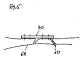
- FIG. 5 shows a schematic representation of a broken bone stabilized with a support plate.
- the broken bone 68 is stabilized by a metal plate 70.
- the screw connections of the metal plate 70 are indicated by broken lines.
- FIG. 7 shows a section through the surface of a stimulation device according to the invention.
- the outer surface of the stimulation device 10 is provided with an electroconductive coating which enlarges the surface and avoids the attachment of bacteria, preferably silver particles 30 present in colloidal state.
- the coating of the surface is mediated by a porous intermediate layer 32, which consists for example of plastic or ceramic. It is also possible that the silver particles are additionally or alternatively incorporated in the intermediate layer. This can be realized by applying a ceramic-silver emulsion.
- the electrical contact between the surface of the stimulation device 10 and the electrically conductive coating 30 is via body fluid or by direct contact of the surface of the stimulation device 10 provided with the coating 30 in the region of the pores of the porous surface.
- the bactericidal coating As a result of the bactericidal coating, the accumulation of bacteria is impeded even without electrical potentials made available via the surface of the stimulation device. This effect is enhanced in the context of the present invention by the induced electric fields. Furthermore, the effect of the induced electric field on the surrounding tissue is favored, since the electrically conductive coating increases the contact surface between tissue and electrode. As a result, the positive biological effects can be improved thereby, or simpler and smaller devices can be used while maintaining a given quality, which relates in particular to the coil arrangement and the equipment generating the external alternating magnetic field.
Landscapes
- Health & Medical Sciences (AREA)
- Life Sciences & Earth Sciences (AREA)
- Animal Behavior & Ethology (AREA)
- General Health & Medical Sciences (AREA)
- Biomedical Technology (AREA)
- Nuclear Medicine, Radiotherapy & Molecular Imaging (AREA)
- Radiology & Medical Imaging (AREA)
- Veterinary Medicine (AREA)
- Public Health (AREA)
- Engineering & Computer Science (AREA)
- Cardiology (AREA)
- Heart & Thoracic Surgery (AREA)
- Cell Biology (AREA)
- Orthopedic Medicine & Surgery (AREA)
- Prostheses (AREA)
- Electrotherapy Devices (AREA)
- Magnetic Treatment Devices (AREA)
- Surgical Instruments (AREA)
Claims (11)
- Dispositif de stimulation (10) pour l'implantation dans le corps human, comportant un agencement bobine (12), une première électrode (16) connectée à un premier pôle (14) de l'agencement bobine et une deuxième électrode (20) connectée à un deuxième pôle (18) de l'agencement bobine; le dispositif de stimulation (10) comporte une hampe (22) qui définit un axe, l'agencement bobine est disposé dans une zone de réception (24) située radialement à l'intérieur et au moins une partie de la hampe (22) forme la première électrode (16), caractérisé en ce que la deuxième électrode (20) est un élément élastique de contact.
- Dispositif de stimulation selon la revendication 1, caractérisé en ce qu'une pièce terminale (26) isolatrice électrique est raccordée à une zone terminale de la hampe (22), un raccord électrique étant mené au travers la pièce terminale à l'élément élastique de contact (20) qui est agencé sur la face de la pièce terminale détournée de la hampe.
- Dispositif de stimulation selon la revendication 2, caractérisé en ce qu'un élément de contact (20) est fixé dans la pièce terminale.
- Dispositif de stimulation selon l'une des revendications précédentes, caractérisé en ce que l'élément de contact (20) consiste du moins en partie d'acier qui est dur comme un ressort.
- Dispositif de stimulation selon l'une des revendications précédentes, caractérisé en ce que l'élément de contact (20) consiste du moins un partie de titane qui est dur comme un ressort.
- Dispositif de stimulation selon l'une des revendications précédentes, caractérisé en ce que l'élément de contact (20) comporte au moins un fil ondulé.
- Dispositif de stimulation selon l'une des revendications précédentes, caractérisé en ce que l'élément de contact (20) comporte au moins un fil en spirale.
- Dispositif de stimulation selon l'une des revendications précédentes, caractérisé en ce que le dispositif de stimulation est une vis d'os (10) qui comporte un filet extérieur (28).
- Dispositif de stimulation selon l'une des revendications précédentes, caractérisé en ce que la surface extérieure du dispositif de stimulation (10) est garnie, du moins en partie, d'un revêtement (30) qui agrandit la surface du dispositif de stimulation et qui évite le dépôt de bactéries.
- Dispositif de stimulation selon la revendication 9, caractérisé en ce que la revêtement (30) comporte de l'argent.
- Dispositif de stimulation selon la revendication 9 ou 10, caractérisé en ce qu'une couche intermédiaire poreuse (32) est prévue entre la surface du dispositif de stimulation et le revêtement (30).
Applications Claiming Priority (3)
| Application Number | Priority Date | Filing Date | Title |
|---|---|---|---|
| DE102006019955 | 2006-05-01 | ||
| DE102006032957A DE102006032957B4 (de) | 2006-05-01 | 2006-07-17 | Stimulationsvorrichtung für die Osteosynthese und die Endoprothetik |
| PCT/DE2007/000764 WO2007124731A2 (fr) | 2006-05-01 | 2007-04-27 | Dispositif de stimulation pour ostéosynthèse et endoprothèse |
Publications (2)
| Publication Number | Publication Date |
|---|---|
| EP2012869A2 EP2012869A2 (fr) | 2009-01-14 |
| EP2012869B1 true EP2012869B1 (fr) | 2013-04-17 |
Family
ID=38537525
Family Applications (1)
| Application Number | Title | Priority Date | Filing Date |
|---|---|---|---|
| EP07722321.2A Not-in-force EP2012869B1 (fr) | 2006-05-01 | 2007-04-27 | Dispositif de stimulation pour ostéosynthèse et endoprothèse |
Country Status (8)
| Country | Link |
|---|---|
| US (1) | US20100036467A1 (fr) |
| EP (1) | EP2012869B1 (fr) |
| JP (1) | JP5062640B2 (fr) |
| CN (1) | CN101437569B (fr) |
| AU (1) | AU2007246020B2 (fr) |
| CA (1) | CA2650117C (fr) |
| DE (1) | DE102006032957B4 (fr) |
| WO (1) | WO2007124731A2 (fr) |
Families Citing this family (26)
| Publication number | Priority date | Publication date | Assignee | Title |
|---|---|---|---|---|
| DE102007063027A1 (de) * | 2007-12-28 | 2009-07-09 | Neue Magnetodyn Gmbh | Kontaktvorrichtung für die Osteosynthese |
| DE102008021575A1 (de) * | 2008-04-30 | 2009-11-05 | Neue Magnetodyn Gmbh | Vorrichtung zum Stimulieren eines Heilungsprozesses |
| DE102009007195A1 (de) * | 2009-02-03 | 2010-08-05 | Neue Magnetodyn Gmbh | Elektrische Hüftgelenkprothese |
| CN105011997B (zh) * | 2009-09-04 | 2019-04-26 | 诺威适骨科专科公司 | 骨生长装置及方法 |
| DK2473116T3 (da) | 2009-09-04 | 2020-01-27 | Nuvasive Specialized Orthopedics Inc | Knoglevækstindretning |
| CN102210903A (zh) * | 2010-04-02 | 2011-10-12 | 鼎迈医疗科技(苏州)有限公司 | 植入式神经电刺激系统的延伸导线保护套 |
| DE202013004045U1 (de) | 2013-05-02 | 2013-06-14 | Paul Schaffrath | Dentalimplantat |
| KR101599603B1 (ko) * | 2013-08-26 | 2016-03-03 | 경북대학교 산학협력단 | 의료용 삽입 장치 |
| DE102014108261A1 (de) | 2014-06-12 | 2016-01-07 | Universität Rostock | Implantat |
| KR101639887B1 (ko) | 2014-11-11 | 2016-07-14 | 경북대학교 산학협력단 | 경추 고정 시스템 및 경추 고정용 기구에 사용되는 드라이버 |
| KR101608949B1 (ko) | 2014-11-19 | 2016-04-04 | 경북대학교 산학협력단 | 경추 고정 시스템, 경추 고정용 기구 및 경추 고정용 기구에 사용되는 드라이버 |
| US10420597B2 (en) * | 2014-12-16 | 2019-09-24 | Arthrex, Inc. | Surgical implant with porous region |
| US11147598B2 (en) * | 2015-04-20 | 2021-10-19 | Bioscience Medical Group Ltd. | Bone fixation apparatus |
| CN104941065B (zh) * | 2015-06-30 | 2018-02-27 | 北京品驰医疗设备有限公司 | 植入式神经电刺激系统以及应用于该植入式神经电刺激系统的保护套 |
| KR101670768B1 (ko) | 2015-07-16 | 2016-10-31 | 경북대학교 산학협력단 | 나사못 앵커 조립체 |
| US10874445B2 (en) | 2015-10-13 | 2020-12-29 | Kyungpook National University Industry-Academic Cooperation Foundation | Screw fixing apparatus |
| KR101712610B1 (ko) | 2015-12-29 | 2017-03-06 | 경북대학교 산학협력단 | 로드 커넥터 |
| KR101791004B1 (ko) | 2016-06-08 | 2017-10-27 | 경북대학교 산학협력단 | 나사못 앵커 조립체 및 나사못 앵커 조립체를 척추 나사못 고정술에 사용하는 방법 |
| US10751527B2 (en) | 2016-10-03 | 2020-08-25 | II Erich W. Wolf | Device and method for percutaneous placement and anchoring of stimulating electrodes in spine |
| CN107961067B (zh) * | 2018-01-12 | 2021-05-07 | 四川大学华西医院 | 外侧入口胫骨髓内针 |
| US11331504B2 (en) | 2018-04-10 | 2022-05-17 | Neue Magnetodyn Gmbh | Bipolar bone anchor with connection for electrostimulation |
| US11305112B2 (en) * | 2018-05-16 | 2022-04-19 | DePuy Synthes Products, Inc. | Electrical stimulation implants |
| US11457934B2 (en) | 2018-07-24 | 2022-10-04 | DePuy Synthes Products, Inc. | Intramedullary nail with wire or magnet for targeting of a bone-anchor locking hole |
| CN110786921B (zh) * | 2019-11-05 | 2021-04-13 | 邹祥 | 一种医用骨钉 |
| DE102020116929A1 (de) | 2020-06-26 | 2021-12-30 | Universität Rostock | Endoprothese, Verfahren zu deren Herstellung und Verwendung einer Endoprothese |
| AU2022339915A1 (en) * | 2021-08-30 | 2024-04-04 | Nanovis, LLC | Devices and methods for treating infected tissue |
Family Cites Families (9)
| Publication number | Priority date | Publication date | Assignee | Title |
|---|---|---|---|---|
| DE2742741A1 (de) * | 1977-09-22 | 1979-04-05 | Kraus Werner | Zusatzvorrichtung zum anbringen von einer aufnehmerspule und elektrodenanschluessen an einem osteosyntheseimplantat |
| US4909263A (en) * | 1988-10-28 | 1990-03-20 | C. R. Bard, Inc. | Method and apparatus for fitting a patient with a body cavity electrode |
| US5292252A (en) * | 1992-12-14 | 1994-03-08 | Impla-Med, Inc. | Stimulator healing cap |
| US5397342A (en) * | 1993-06-07 | 1995-03-14 | Cardiac Pacemakers, Inc. | Resilient structurally coupled and electrically independent electrodes |
| US5476501A (en) * | 1994-05-06 | 1995-12-19 | Medtronic, Inc. | Silicon insulated extendable/retractable screw-in pacing lead with high efficiency torque transfer |
| DE19544750A1 (de) * | 1995-11-30 | 1997-06-05 | Christoph Rehberg | Implantierbare Vorrichtung mit Innenelektrode zur Förderung des Gewebewachstums |
| DE19928449C1 (de) * | 1999-06-23 | 2001-03-08 | Geot Ges Fuer Elektro Oseto Th | Knochenschraube mit Vorrichtung zur Elektrostimulation |
| US7206638B2 (en) * | 2002-11-20 | 2007-04-17 | The Nemours Foundation | Electrical current induced inhibition of bone growth |
| US20040176829A1 (en) * | 2003-03-04 | 2004-09-09 | Japan General Medical Institute Co., Ltd. | Electrode device for myocardial and the like |
-
2006
- 2006-07-17 DE DE102006032957A patent/DE102006032957B4/de not_active Expired - Fee Related
-
2007
- 2007-04-27 US US12/298,398 patent/US20100036467A1/en not_active Abandoned
- 2007-04-27 JP JP2009508113A patent/JP5062640B2/ja not_active Expired - Fee Related
- 2007-04-27 CN CN2007800158225A patent/CN101437569B/zh not_active Expired - Fee Related
- 2007-04-27 EP EP07722321.2A patent/EP2012869B1/fr not_active Not-in-force
- 2007-04-27 WO PCT/DE2007/000764 patent/WO2007124731A2/fr active Application Filing
- 2007-04-27 CA CA2650117A patent/CA2650117C/fr not_active Expired - Fee Related
- 2007-04-27 AU AU2007246020A patent/AU2007246020B2/en not_active Ceased
Also Published As
| Publication number | Publication date |
|---|---|
| US20100036467A1 (en) | 2010-02-11 |
| CN101437569B (zh) | 2013-08-14 |
| CA2650117C (fr) | 2011-09-27 |
| DE102006032957A1 (de) | 2007-11-08 |
| WO2007124731B1 (fr) | 2008-03-20 |
| CN101437569A (zh) | 2009-05-20 |
| JP5062640B2 (ja) | 2012-10-31 |
| WO2007124731A2 (fr) | 2007-11-08 |
| AU2007246020B2 (en) | 2011-04-07 |
| WO2007124731A3 (fr) | 2008-01-31 |
| AU2007246020A1 (en) | 2007-11-08 |
| DE102006032957B4 (de) | 2008-08-07 |
| EP2012869A2 (fr) | 2009-01-14 |
| JP2009535134A (ja) | 2009-10-01 |
| CA2650117A1 (fr) | 2007-11-08 |
Similar Documents
| Publication | Publication Date | Title |
|---|---|---|
| EP2012869B1 (fr) | Dispositif de stimulation pour ostéosynthèse et endoprothèse | |
| EP1847227B1 (fr) | Système de clou électrique | |
| EP2050482B1 (fr) | Dispositif implantable, système de production de champs électromagnétiques localisés dans la zone d'un implant et agencement de bobines | |
| EP2467190B1 (fr) | Dispositif de polarisation et système d'implantation | |
| EP1492591B1 (fr) | Dispositif pour favoriser la croissance osseuse, notamment pour la synthese osseuse de fragments d'os et/ou la fixation de fractures osseuses | |
| WO2009083086A2 (fr) | Dispositif de contact pour l'ostéosynthèse | |
| EP1148830A1 (fr) | Vis a os | |
| DE20020649U1 (de) | Vorrichtung für den chirurgischen oder therapeutischen Gebrauch, insbesondere Implantate und chirurgische Instrumente sowie deren Zubehör | |
| EP1607066A1 (fr) | Calotte de tête fémorale implantable avec dispositif pour la stimulation électrique de tissu | |
| DE2314573A1 (de) | Geraet zur foerderung von heilungsprozessen | |
| EP2421475B1 (fr) | Prothèse de hanche électrique | |
| EP0071658B1 (fr) | Dispositif pour le maintien de la vitalité de tissus osseux | |
| DE202006014950U1 (de) | Hüftimplantat und Modul für Hüftimplantat | |
| DE102009049175A1 (de) | Vorrichtung zum Verabreichen von Arzneimitteln und zum Beeinflussen von Arzneimittelwirkungen | |
| DE102014108261A1 (de) | Implantat | |
| DE102018112298A1 (de) | Vorrichtung zur Behandlung und/oder Vermeidung von Biofilmen und/oder Infektionen an permanent bestehenden oder temporär bestehenden Hautdurchtritten | |
| WO2017097906A1 (fr) | Articulation de gros orteil artificielle, notamment à base de ceramique | |
| CH662279A5 (en) | Device for the biological stimulation of tissues | |
| DE102015104583A1 (de) | Implantierbare Vorrichtung zum Ausbilden einer permanenten Hautdurchführung |
Legal Events
| Date | Code | Title | Description |
|---|---|---|---|
| PUAI | Public reference made under article 153(3) epc to a published international application that has entered the european phase |
Free format text: ORIGINAL CODE: 0009012 |
|
| 17P | Request for examination filed |
Effective date: 20081022 |
|
| AK | Designated contracting states |
Kind code of ref document: A2 Designated state(s): AT BE BG CH CY CZ DE DK EE ES FI FR GB GR HU IE IS IT LI LT LU LV MC MT NL PL PT RO SE SI SK TR |
|
| AX | Request for extension of the european patent |
Extension state: AL BA HR MK RS |
|
| RIN1 | Information on inventor provided before grant (corrected) |
Inventor name: KRAUS, STEPHANIE Inventor name: STEPHAN, HERIBERT Inventor name: KRAUS, WERNER |
|
| DAX | Request for extension of the european patent (deleted) | ||
| 17Q | First examination report despatched |
Effective date: 20090713 |
|
| RIC1 | Information provided on ipc code assigned before grant |
Ipc: A61N 1/05 20060101AFI20120808BHEP Ipc: A61N 1/32 20060101ALI20120808BHEP Ipc: A61B 17/58 20060101ALI20120808BHEP |
|
| GRAP | Despatch of communication of intention to grant a patent |
Free format text: ORIGINAL CODE: EPIDOSNIGR1 |
|
| GRAS | Grant fee paid |
Free format text: ORIGINAL CODE: EPIDOSNIGR3 |
|
| GRAA | (expected) grant |
Free format text: ORIGINAL CODE: 0009210 |
|
| AK | Designated contracting states |
Kind code of ref document: B1 Designated state(s): AT BE BG CH CY CZ DE DK EE ES FI FR GB GR HU IE IS IT LI LT LU LV MC MT NL PL PT RO SE SI SK TR |
|
| REG | Reference to a national code |
Ref country code: GB Ref legal event code: FG4D Free format text: NOT ENGLISH |
|
| REG | Reference to a national code |
Ref country code: CH Ref legal event code: EP |
|
| REG | Reference to a national code |
Ref country code: IE Ref legal event code: FG4D Free format text: LANGUAGE OF EP DOCUMENT: GERMAN |
|
| REG | Reference to a national code |
Ref country code: AT Ref legal event code: REF Ref document number: 606862 Country of ref document: AT Kind code of ref document: T Effective date: 20130515 |
|
| REG | Reference to a national code |
Ref country code: DE Ref legal event code: R096 Ref document number: 502007011623 Country of ref document: DE Effective date: 20130613 |
|
| REG | Reference to a national code |
Ref country code: LT Ref legal event code: MG4D |
|
| REG | Reference to a national code |
Ref country code: NL Ref legal event code: VDEP Effective date: 20130417 |
|
| BERE | Be: lapsed |
Owner name: NEUE MAGNETODYN G.M.B.H. Effective date: 20130430 |
|
| PG25 | Lapsed in a contracting state [announced via postgrant information from national office to epo] |
Ref country code: GR Free format text: LAPSE BECAUSE OF FAILURE TO SUBMIT A TRANSLATION OF THE DESCRIPTION OR TO PAY THE FEE WITHIN THE PRESCRIBED TIME-LIMIT Effective date: 20130718 Ref country code: FI Free format text: LAPSE BECAUSE OF FAILURE TO SUBMIT A TRANSLATION OF THE DESCRIPTION OR TO PAY THE FEE WITHIN THE PRESCRIBED TIME-LIMIT Effective date: 20130417 Ref country code: LT Free format text: LAPSE BECAUSE OF FAILURE TO SUBMIT A TRANSLATION OF THE DESCRIPTION OR TO PAY THE FEE WITHIN THE PRESCRIBED TIME-LIMIT Effective date: 20130417 Ref country code: SE Free format text: LAPSE BECAUSE OF FAILURE TO SUBMIT A TRANSLATION OF THE DESCRIPTION OR TO PAY THE FEE WITHIN THE PRESCRIBED TIME-LIMIT Effective date: 20130417 Ref country code: IS Free format text: LAPSE BECAUSE OF FAILURE TO SUBMIT A TRANSLATION OF THE DESCRIPTION OR TO PAY THE FEE WITHIN THE PRESCRIBED TIME-LIMIT Effective date: 20130817 Ref country code: PT Free format text: LAPSE BECAUSE OF FAILURE TO SUBMIT A TRANSLATION OF THE DESCRIPTION OR TO PAY THE FEE WITHIN THE PRESCRIBED TIME-LIMIT Effective date: 20130819 Ref country code: SI Free format text: LAPSE BECAUSE OF FAILURE TO SUBMIT A TRANSLATION OF THE DESCRIPTION OR TO PAY THE FEE WITHIN THE PRESCRIBED TIME-LIMIT Effective date: 20130417 Ref country code: ES Free format text: LAPSE BECAUSE OF FAILURE TO SUBMIT A TRANSLATION OF THE DESCRIPTION OR TO PAY THE FEE WITHIN THE PRESCRIBED TIME-LIMIT Effective date: 20130728 |
|
| PG25 | Lapsed in a contracting state [announced via postgrant information from national office to epo] |
Ref country code: CY Free format text: LAPSE BECAUSE OF FAILURE TO SUBMIT A TRANSLATION OF THE DESCRIPTION OR TO PAY THE FEE WITHIN THE PRESCRIBED TIME-LIMIT Effective date: 20130417 Ref country code: BG Free format text: LAPSE BECAUSE OF FAILURE TO SUBMIT A TRANSLATION OF THE DESCRIPTION OR TO PAY THE FEE WITHIN THE PRESCRIBED TIME-LIMIT Effective date: 20130717 Ref country code: PL Free format text: LAPSE BECAUSE OF FAILURE TO SUBMIT A TRANSLATION OF THE DESCRIPTION OR TO PAY THE FEE WITHIN THE PRESCRIBED TIME-LIMIT Effective date: 20130417 Ref country code: LV Free format text: LAPSE BECAUSE OF FAILURE TO SUBMIT A TRANSLATION OF THE DESCRIPTION OR TO PAY THE FEE WITHIN THE PRESCRIBED TIME-LIMIT Effective date: 20130417 |
|
| REG | Reference to a national code |
Ref country code: CH Ref legal event code: PL |
|
| REG | Reference to a national code |
Ref country code: IE Ref legal event code: MM4A |
|
| PG25 | Lapsed in a contracting state [announced via postgrant information from national office to epo] |
Ref country code: EE Free format text: LAPSE BECAUSE OF FAILURE TO SUBMIT A TRANSLATION OF THE DESCRIPTION OR TO PAY THE FEE WITHIN THE PRESCRIBED TIME-LIMIT Effective date: 20130417 Ref country code: SK Free format text: LAPSE BECAUSE OF FAILURE TO SUBMIT A TRANSLATION OF THE DESCRIPTION OR TO PAY THE FEE WITHIN THE PRESCRIBED TIME-LIMIT Effective date: 20130417 Ref country code: DK Free format text: LAPSE BECAUSE OF FAILURE TO SUBMIT A TRANSLATION OF THE DESCRIPTION OR TO PAY THE FEE WITHIN THE PRESCRIBED TIME-LIMIT Effective date: 20130417 Ref country code: BE Free format text: LAPSE BECAUSE OF NON-PAYMENT OF DUE FEES Effective date: 20130430 Ref country code: MC Free format text: LAPSE BECAUSE OF FAILURE TO SUBMIT A TRANSLATION OF THE DESCRIPTION OR TO PAY THE FEE WITHIN THE PRESCRIBED TIME-LIMIT Effective date: 20130417 Ref country code: CH Free format text: LAPSE BECAUSE OF NON-PAYMENT OF DUE FEES Effective date: 20130430 Ref country code: CZ Free format text: LAPSE BECAUSE OF FAILURE TO SUBMIT A TRANSLATION OF THE DESCRIPTION OR TO PAY THE FEE WITHIN THE PRESCRIBED TIME-LIMIT Effective date: 20130417 Ref country code: LI Free format text: LAPSE BECAUSE OF NON-PAYMENT OF DUE FEES Effective date: 20130430 |
|
| PLBE | No opposition filed within time limit |
Free format text: ORIGINAL CODE: 0009261 |
|
| STAA | Information on the status of an ep patent application or granted ep patent |
Free format text: STATUS: NO OPPOSITION FILED WITHIN TIME LIMIT |
|
| PG25 | Lapsed in a contracting state [announced via postgrant information from national office to epo] |
Ref country code: RO Free format text: LAPSE BECAUSE OF FAILURE TO SUBMIT A TRANSLATION OF THE DESCRIPTION OR TO PAY THE FEE WITHIN THE PRESCRIBED TIME-LIMIT Effective date: 20130417 Ref country code: IT Free format text: LAPSE BECAUSE OF FAILURE TO SUBMIT A TRANSLATION OF THE DESCRIPTION OR TO PAY THE FEE WITHIN THE PRESCRIBED TIME-LIMIT Effective date: 20130417 Ref country code: NL Free format text: LAPSE BECAUSE OF FAILURE TO SUBMIT A TRANSLATION OF THE DESCRIPTION OR TO PAY THE FEE WITHIN THE PRESCRIBED TIME-LIMIT Effective date: 20130417 |
|
| 26N | No opposition filed |
Effective date: 20140120 |
|
| PG25 | Lapsed in a contracting state [announced via postgrant information from national office to epo] |
Ref country code: IE Free format text: LAPSE BECAUSE OF NON-PAYMENT OF DUE FEES Effective date: 20130427 |
|
| REG | Reference to a national code |
Ref country code: DE Ref legal event code: R097 Ref document number: 502007011623 Country of ref document: DE Effective date: 20140120 |
|
| REG | Reference to a national code |
Ref country code: AT Ref legal event code: MM01 Ref document number: 606862 Country of ref document: AT Kind code of ref document: T Effective date: 20130427 |
|
| PG25 | Lapsed in a contracting state [announced via postgrant information from national office to epo] |
Ref country code: AT Free format text: LAPSE BECAUSE OF NON-PAYMENT OF DUE FEES Effective date: 20130427 |
|
| PG25 | Lapsed in a contracting state [announced via postgrant information from national office to epo] |
Ref country code: MT Free format text: LAPSE BECAUSE OF FAILURE TO SUBMIT A TRANSLATION OF THE DESCRIPTION OR TO PAY THE FEE WITHIN THE PRESCRIBED TIME-LIMIT Effective date: 20130417 |
|
| PG25 | Lapsed in a contracting state [announced via postgrant information from national office to epo] |
Ref country code: TR Free format text: LAPSE BECAUSE OF FAILURE TO SUBMIT A TRANSLATION OF THE DESCRIPTION OR TO PAY THE FEE WITHIN THE PRESCRIBED TIME-LIMIT Effective date: 20130417 |
|
| PG25 | Lapsed in a contracting state [announced via postgrant information from national office to epo] |
Ref country code: LU Free format text: LAPSE BECAUSE OF NON-PAYMENT OF DUE FEES Effective date: 20130427 Ref country code: HU Free format text: LAPSE BECAUSE OF FAILURE TO SUBMIT A TRANSLATION OF THE DESCRIPTION OR TO PAY THE FEE WITHIN THE PRESCRIBED TIME-LIMIT; INVALID AB INITIO Effective date: 20070427 |
|
| REG | Reference to a national code |
Ref country code: FR Ref legal event code: PLFP Year of fee payment: 9 |
|
| REG | Reference to a national code |
Ref country code: FR Ref legal event code: PLFP Year of fee payment: 10 |
|
| REG | Reference to a national code |
Ref country code: FR Ref legal event code: PLFP Year of fee payment: 11 |
|
| REG | Reference to a national code |
Ref country code: FR Ref legal event code: PLFP Year of fee payment: 12 |
|
| PGFP | Annual fee paid to national office [announced via postgrant information from national office to epo] |
Ref country code: DE Payment date: 20200423 Year of fee payment: 14 Ref country code: FR Payment date: 20200421 Year of fee payment: 14 |
|
| PGFP | Annual fee paid to national office [announced via postgrant information from national office to epo] |
Ref country code: GB Payment date: 20200423 Year of fee payment: 14 |
|
| REG | Reference to a national code |
Ref country code: DE Ref legal event code: R119 Ref document number: 502007011623 Country of ref document: DE |
|
| GBPC | Gb: european patent ceased through non-payment of renewal fee |
Effective date: 20210427 |
|
| PG25 | Lapsed in a contracting state [announced via postgrant information from national office to epo] |
Ref country code: DE Free format text: LAPSE BECAUSE OF NON-PAYMENT OF DUE FEES Effective date: 20211103 Ref country code: FR Free format text: LAPSE BECAUSE OF NON-PAYMENT OF DUE FEES Effective date: 20210430 Ref country code: GB Free format text: LAPSE BECAUSE OF NON-PAYMENT OF DUE FEES Effective date: 20210427 |