EP2012869B1 - Stimulationsvorrichtung für die osteosynthese und die endoprothetik - Google Patents
Stimulationsvorrichtung für die osteosynthese und die endoprothetik Download PDFInfo
- Publication number
- EP2012869B1 EP2012869B1 EP07722321.2A EP07722321A EP2012869B1 EP 2012869 B1 EP2012869 B1 EP 2012869B1 EP 07722321 A EP07722321 A EP 07722321A EP 2012869 B1 EP2012869 B1 EP 2012869B1
- Authority
- EP
- European Patent Office
- Prior art keywords
- stimulation device
- contact element
- electrode
- shaft
- bone
- Prior art date
- Legal status (The legal status is an assumption and is not a legal conclusion. Google has not performed a legal analysis and makes no representation as to the accuracy of the status listed.)
- Not-in-force
Links
Images


Classifications
-
- A—HUMAN NECESSITIES
- A61—MEDICAL OR VETERINARY SCIENCE; HYGIENE
- A61N—ELECTROTHERAPY; MAGNETOTHERAPY; RADIATION THERAPY; ULTRASOUND THERAPY
- A61N1/00—Electrotherapy; Circuits therefor
- A61N1/18—Applying electric currents by contact electrodes
- A61N1/32—Applying electric currents by contact electrodes alternating or intermittent currents
- A61N1/326—Applying electric currents by contact electrodes alternating or intermittent currents for promoting growth of cells, e.g. bone cells
-
- A—HUMAN NECESSITIES
- A61—MEDICAL OR VETERINARY SCIENCE; HYGIENE
- A61N—ELECTROTHERAPY; MAGNETOTHERAPY; RADIATION THERAPY; ULTRASOUND THERAPY
- A61N1/00—Electrotherapy; Circuits therefor
- A61N1/02—Details
- A61N1/04—Electrodes
- A61N1/05—Electrodes for implantation or insertion into the body, e.g. heart electrode
-
- A—HUMAN NECESSITIES
- A61—MEDICAL OR VETERINARY SCIENCE; HYGIENE
- A61B—DIAGNOSIS; SURGERY; IDENTIFICATION
- A61B17/00—Surgical instruments, devices or methods, e.g. tourniquets
- A61B17/56—Surgical instruments or methods for treatment of bones or joints; Devices specially adapted therefor
- A61B17/58—Surgical instruments or methods for treatment of bones or joints; Devices specially adapted therefor for osteosynthesis, e.g. bone plates, screws, setting implements or the like
- A61B17/68—Internal fixation devices, including fasteners and spinal fixators, even if a part thereof projects from the skin
- A61B17/72—Intramedullary pins, nails or other devices
-
- A—HUMAN NECESSITIES
- A61—MEDICAL OR VETERINARY SCIENCE; HYGIENE
- A61B—DIAGNOSIS; SURGERY; IDENTIFICATION
- A61B17/00—Surgical instruments, devices or methods, e.g. tourniquets
- A61B17/56—Surgical instruments or methods for treatment of bones or joints; Devices specially adapted therefor
- A61B17/58—Surgical instruments or methods for treatment of bones or joints; Devices specially adapted therefor for osteosynthesis, e.g. bone plates, screws, setting implements or the like
- A61B17/68—Internal fixation devices, including fasteners and spinal fixators, even if a part thereof projects from the skin
- A61B17/80—Cortical plates, i.e. bone plates; Instruments for holding or positioning cortical plates, or for compressing bones attached to cortical plates
-
- A—HUMAN NECESSITIES
- A61—MEDICAL OR VETERINARY SCIENCE; HYGIENE
- A61B—DIAGNOSIS; SURGERY; IDENTIFICATION
- A61B17/00—Surgical instruments, devices or methods, e.g. tourniquets
- A61B17/56—Surgical instruments or methods for treatment of bones or joints; Devices specially adapted therefor
- A61B17/58—Surgical instruments or methods for treatment of bones or joints; Devices specially adapted therefor for osteosynthesis, e.g. bone plates, screws, setting implements or the like
- A61B17/68—Internal fixation devices, including fasteners and spinal fixators, even if a part thereof projects from the skin
- A61B17/84—Fasteners therefor or fasteners being internal fixation devices
- A61B17/86—Pins or screws or threaded wires; nuts therefor
-
- A—HUMAN NECESSITIES
- A61—MEDICAL OR VETERINARY SCIENCE; HYGIENE
- A61F—FILTERS IMPLANTABLE INTO BLOOD VESSELS; PROSTHESES; DEVICES PROVIDING PATENCY TO, OR PREVENTING COLLAPSING OF, TUBULAR STRUCTURES OF THE BODY, e.g. STENTS; ORTHOPAEDIC, NURSING OR CONTRACEPTIVE DEVICES; FOMENTATION; TREATMENT OR PROTECTION OF EYES OR EARS; BANDAGES, DRESSINGS OR ABSORBENT PADS; FIRST-AID KITS
- A61F2/00—Filters implantable into blood vessels; Prostheses, i.e. artificial substitutes or replacements for parts of the body; Appliances for connecting them with the body; Devices providing patency to, or preventing collapsing of, tubular structures of the body, e.g. stents
- A61F2/02—Prostheses implantable into the body
- A61F2/30—Joints
- A61F2/32—Joints for the hip
-
- A—HUMAN NECESSITIES
- A61—MEDICAL OR VETERINARY SCIENCE; HYGIENE
- A61N—ELECTROTHERAPY; MAGNETOTHERAPY; RADIATION THERAPY; ULTRASOUND THERAPY
- A61N1/00—Electrotherapy; Circuits therefor
- A61N1/18—Applying electric currents by contact electrodes
- A61N1/32—Applying electric currents by contact electrodes alternating or intermittent currents
- A61N1/36—Applying electric currents by contact electrodes alternating or intermittent currents for stimulation
- A61N1/372—Arrangements in connection with the implantation of stimulators
- A61N1/378—Electrical supply
- A61N1/3787—Electrical supply from an external energy source
Definitions
- the invention relates to a stimulation device for implantation in the human body, comprising a coil arrangement, a first electrode connected to a first pole of the coil arrangement and a second electrode connected to a second pole of the coil arrangement.
- Such stimulation devices are known in the field of osteosynthesis and endoprosthetics.
- a stimulation device with the features of the preamble of claim 1 is made US-B-6,778,861 known.
- the osteosynthesis serves to load-stable fixation of the fragments of a broken or diseased bone in its uninjured, natural shape by implanted screws, support plates, wires, bone marrow nails and the like, which are generally made of stainless steel or titanium alloys. These osteosynthetic agents allow for rapid mobilization of the patient while immobilizing the damaged bone, which is an essential prerequisite for its healing.
- the endoprosthesis serves for the implantation of prostheses, in particular joint prostheses, for example in the hip.
- MRSA biologically multi-resistant Staphylococcus aureus
- the technique of transmission works according to the transformer principle:
- the injured or diseased body region is characterized by an extremely low frequency sinusoidal magnetic field having a frequency of about 1 to 100 Hz - preferably from 3 to 30 Hz - and a magnetic flux density of 0.5 to 5 Flooded mT (5 to 50 gauss), which is generated by a functional current generator in one or more - primary - outer current coils, in which the body part provided with the osteosynthesis means or the endoprosthesis is introduced.
- These extremely low-frequency electromagnetic fields penetrate the tissue largely lossless, including any clothing and a cast, as well as the non-magnetic (austenitic) supporting metals of osteosynthesis or endoprosthetics.
- the so-called transformer implanted in electrical contact with these a - secondary - coil assembly.
- the induced in the transformer electro-potentials are brought so in the area of the bone lesion and generally in the adjacent to the osteosynthetic agent or endoprosthesis tissue effect.
- the treatment parameters are electrical voltage, frequency, Intensity, waveform and treatment time determined by the indication specific programming of the inducing magnetic field determining function current generator.
- the invention has for its object to provide a technique for avoiding the need for implant replacement available, especially in high-risk patients.
- the invention is based on the generic stimulation device in that the second electrode as elastic Contact element is formed. This makes it possible to electrically contact metal parts implanted in the bone region via the elastic contact element. In this way, the already implanted metal part to the electrode, while the electrically connected to the coil assembly part of the stimulation device forms the counter electrode thereto. Consequently, without replacement of the implant, this can be included in the therapy described above using low-frequency electromagnetic alternating fields.
- the stimulation device has a shaft defining an axis, the coil arrangement is arranged in a radially inner receiving region of the shaft and at least part of the shaft forms the first electrode.
- the stimulation device is thus designed as an elongate element, whereby it is suitable for insertion into small openings of the body and in particular of the bone.
- the coil assembly can be safely housed liquid and gas tight within the shaft of the stimulation device.
- the invention is advantageously further developed in that an electrically insulating end piece attaches to an end region of the shank, through which an electrical connection is made to the elastic contact element arranged on the side of the end piece facing away from the shank.
- the electrically insulating end piece serves to isolate the elastic contact element from the rest of the electrically conductive device body, and it also allows the implementation of the electrical connection from the coil arrangement arranged in the shaft to the outer contact element.
- the contact element is fixed in the end piece.
- the contact element may be sintered or glued with epoxy resin; additional fasteners are not required.
- the contact element consists at least partially of spring-hard steel.
- the contact element consists at least partially of spring-hard titanium.
- the contact element has at least one corrugated wire.
- the invention may be designed so that the contact element has at least one helical wire.
- the stimulation device is designed as a bone screw having an external thread.
- a bone screw can be advantageously used because it can be securely fixed in bone, so that the relative position of the stimulation device relative to the metal part already implanted does not change or only insignificantly. Furthermore, no further aids need to be implanted for fixing the bone screw. Even if the interpretation of the stimulation device As a bone screw may be preferred, it should be noted that any other forms are conceivable. Occasionally, the implantation of an additional fixation device is required for the fixation of stimulation devices of a different shape.
- the invention is further developed particularly useful in that the outer surface of the stimulation device is at least partially provided with an electrically conductive coating which enlarges the surface of the stimulation device and avoids the accumulation of bacteria.
- Bactericidal coatings are known. If one selects an electrically conductive bactericidal coating which increases the surface area of the stimulation device, the bactericidal effect is enhanced, namely due to the increased surface area for the transmission of the electric field to the surrounding tissue.
- the coating comprises silver.
- a silver coating can be applied directly to implants of steel or titanium alloys by means of a sputtering technique.
- FIG. 1 shows a sectional view of a stimulation device according to the invention for contacting a H
- the stimulation device is designed as a bone screw 10 with external thread 28.
- the external thread 28 is provided in the distal region of the bone screw 10.
- a coil arrangement 12 provided in a receiving area 24 surrounded by the shank 22 of the bone screw 10 is a coil arrangement 12 provided in a receiving area 24 surrounded by the shank 22 of the bone screw 10 .
- the coil assembly 12 includes a magnetic core 34 and a winding 36 mounted thereon.
- a first pole 14 of the coil assembly 12 is connected via an electrical connection 38 and a rectifier assembly 72, 74 to the electrically conductive shaft 22 of the bone screw 14 which forms the first electrode 16 ,
- the rectifier arrangement comprises a diode 72 and an ohmic resistor 74 connected in parallel with the diode 72.
- the second pole 18 of the coil arrangement 12 is connected via a further electrical connection 40 to an elastic contact element 20 arranged at the distal end of the bone screw 10, which is the second electrode forms.
- the electrical connection 40 is guided by an electrically insulating end piece 26, which consists for example of ceramic or polyethylene.
- the end piece 26 is equipped with a central bore 42.
- the bone screw 10 has at its proximal end a screw head 48 having an opening 50 for insertion of a rotary tool.
- the opening 50 may for example form a hexagon socket.
- the rectifier circuit implemented by the diode 72 may be beneficial to the localization of bone growth.
- the first electrode 16 becomes the anode at which bone growth is inhibited or even osteolysis occurs while the contactor 20 and the implant contacted thereby (see, for example, US Pat FIG.
- the rectifier arrangement 72, 74 is dispensable, so that the first pole 14 of the coil arrangement 12 can be connected directly to the first electrode 16.
- FIG. 2 shows a schematic representation of a introduced into a femur stimulation device.
- a femur 52 and a pelvic bone 54 are shown.
- a H-direc bone 52 On the thigh bone 52 a H-kopfkappenprothese 56 is placed.
- Such a H-handedkopfkappenprothese is often the starting point and the focus of bacterial cultures that colonize below the H Commonkopfkappen prosthesis 56.
- the femoral head prosthesis 56 By contacting the femoral head prosthesis 56 with the bone screw 10 -also the distal portion of the bone screw 10 actually hidden by the femoral head prosthesis 56 is shown-the femoral head prosthesis 56 becomes the electrode, while the shaft 22 of the bone screw 10 forms the counter electrode. Consequently, the tissue lying between the electrodes is stimulated by externally applied magnetic fields.
- FIG. 3 shows a schematic representation of two screwed into the femur stimulation devices for contacting with the shaft of a hip joint prosthesis.
- the shaft 58 of a hip joint prosthesis 60 is contacted by two bone screws 10 of the type according to the invention and in this way to the common counterelectrode to the respective shanks 22 of the bone screws 10.
- FIG. 4 shows a schematic representation of a introduced into a tubular bone stimulation device for contacting an intramedullary nail.
- a long bone 62 with a fracture 66 stabilized by an intramedullary nail 64 is shown.
- the intramedullary nail 64 is connected to the electrode by a screwed into the tubular bone 62 according to the invention bone screw 10.
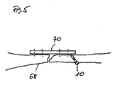
- FIG. 5 shows a schematic representation of a broken bone stabilized with a support plate.
- the broken bone 68 is stabilized by a metal plate 70.
- the screw connections of the metal plate 70 are indicated by broken lines.
- FIG. 7 shows a section through the surface of a stimulation device according to the invention.
- the outer surface of the stimulation device 10 is provided with an electroconductive coating which enlarges the surface and avoids the attachment of bacteria, preferably silver particles 30 present in colloidal state.
- the coating of the surface is mediated by a porous intermediate layer 32, which consists for example of plastic or ceramic. It is also possible that the silver particles are additionally or alternatively incorporated in the intermediate layer. This can be realized by applying a ceramic-silver emulsion.
- the electrical contact between the surface of the stimulation device 10 and the electrically conductive coating 30 is via body fluid or by direct contact of the surface of the stimulation device 10 provided with the coating 30 in the region of the pores of the porous surface.
- the bactericidal coating As a result of the bactericidal coating, the accumulation of bacteria is impeded even without electrical potentials made available via the surface of the stimulation device. This effect is enhanced in the context of the present invention by the induced electric fields. Furthermore, the effect of the induced electric field on the surrounding tissue is favored, since the electrically conductive coating increases the contact surface between tissue and electrode. As a result, the positive biological effects can be improved thereby, or simpler and smaller devices can be used while maintaining a given quality, which relates in particular to the coil arrangement and the equipment generating the external alternating magnetic field.
Description
- Die Erfindung betrifft eine Stimulationsvorrichtung zur Implantation in den menschlichen Körper, mit einer Spulenanordnung, einer mit einem ersten Pol der Spulenanordnung verbundenen ersten Elektrode und einer mit einem zweiten Pol der Spulenanordnung verbundenen zweiten Elektrode.
- Derartige Stimulationsvorrichtungen sind auf dem Gebiet der Osteosynthese sowie der Endoprothetik bekannt. Eine Stimulationsvorrichtung mit den Merkmalen des Oberbegriffs des Anspruchs 1 ist aus
US-B-6 778 861 bekannt. - Die Osteosynthese dient der belastungsstabilen Fixation der Fragmente eines gebrochenen oder kranken Knochens in seiner unverletzten, natürlichen Form durch implantierte Schrauben, Stützplatten, Drähte, Knochenmarknägel und dergleichen, die im Allgemeinen aus nicht rostenden Stahl- oder Titanlegierungen gefertigt sind. Diese Osteosynthesemittel ermöglichen die rasche Mobilisierung des Patienten bei gleichzeitiger Ruhigstellung des lädierten Knochens, die eine unerlässliche Voraussetzung für seine Heilung ist.
- Die Endoprothetik dient der Implatation von Prothesen, insbesondere Gelenkprothesen, beispielsweise in der Hüfte.
- Die Zahl der Patienten mit knochen- und gelenktragenden sowie stützenden Metallimplantaten im Skelett ist in den zurückliegenden zwei Jahrzehnten exponentiell angestiegen. Die Gründe hierfür bilden die Zunahme der unfallbedingten komplizierten Knochenfrakturen und ganz besonders auch der degenerativen Erkrankungen der Gelenke (Arthrosen, Nekrosen), die in immer früherem Lebensalter zum künstlichen Gelenkersatz durch eine Endoprothese führen. Mit der Zunahme des Altersdurchschnitts der Menschen um nahezu zehn Jahre - während der zurückliegenden fünf Jahrzehnte - wächst auch der Anspruch auf die beschwerdefreie Funktionsdauer eines Kunstgelenks. Wurde dieser im sechsten bis siebten Jahrzehnt des vergangenen Jahrhunderts mit 15 bis 20 Jahren erfüllt, so steht die Technik heute vor der Aufgabe, eine möglichst verlustfreie Mobilität des Trägers eines Kunstgelenks über bis zu drei Jahrzehnte oder länger zu gewährleisten. Diesem wachsenden Anspruch an die biomechanische Toleranz des biologischen Lagers eines Langzeitimplantates im Knochenskelett versucht man durch verträglichere Materialien, wie Titanlegierungen und patientenindividuelle Formgebungen unter größtmöglicher Schonung der versorgenden Blutgefäße zu entsprechen.
- Trotz der beachtlichen Fortschritte in der Anpassung der Fremdkörperimplantate an die individualbiologischen und - physiologischen Gegebenheiten entstehen mit dem wachsenden Anspruch der Patienten an die Mobilität und die Funktionsdauer des Implantates neue Probleme, die einer stimulierenden Vermittlung zwischen dem Fremdkörper und seinem biologischen Lager bedürfen. Dass diese Aufgabe durch die Applikation extrem niederfrequenter elektromagnetischer Wechselfelder mit einer Frequenz von 3 bis 30 Hz bei reiner Sinusform (Oberwellenanteil < 1 %) in Verbindung mit einer implantierten Spule (Sekundärinduktivität dem sog. Übertrager) im elektrischen Kontakt mit den Metallbestandteiten der Osteosynthese und der Gelenkendoprothetik auch in Fällen der extremen Knochenheilungsstörung zu lösen ist, wurde in zahlreichen Grundlagenexperimenten und klinischen Studien des Antragsstellers innerhalb von dreieinhalb Jahrzehnten nachgewiesen und publiziert. Die Mehrzahl der Patienten mit Stütz- bzw. Gelenkimplantaten war mit Keimen infiziert, die heute als biologisch multiresistent bezeichnet werden (MRSA = Multiresistenter Staphylococcus Aureus) und ein wachsendes Problem in der orthopädischen und unfallchirurgischen Klinik darstellen. Offenbar sind Keime, die sich an Langzeitimplantaten in Form von "Biofilmen" ansiedeln und sich durch Schleimhüllen schützen, für Antibiotika nicht mehr erreichbar. Die Adhärenz von Keimfilmen an Metallimplantaten kann mit der elektrischen Aktivierung Ihrer Oberfläche durch die verfahrensgemäße elektromagnetische Induktion offenbar vermieden werden.
- Die Technik der Übertragung funktioniert nach dem Transformatorprinzip: Die verletzte oder kranke Körperregion wird von einem extrem niederfrequenten sinusförmig verlaufenden Magnetfeld mit einer Frequenz von ca. 1 bis 100 Hz - vorzugsweise von 3 bis 30 Hz - und einer magnetischen Flussdichte von 0,5 bis 5 mT (5 bis 50 Gauß) durchflutet, das durch einen Funktionsstromgenerator in einer oder mehreren - primären - äußeren Stromspulen erzeugt wird, in die das mit den Osteosynthesemitteln oder der Endoprothese versehene Körperteil eingebracht wird. Diese extrem niederfrequenten elektromagnetischen Felder durchdringen weitgehend verlustfrei das Gewebe, einschließlich eventuelle Kleidung und einen Gipsverband, sowie die unmagnetischen (austenitischen) Stützmetalle der Osteosynthese oder der Endoprothetik. Im elektrischen Kontakt mit diesen wird eine - sekundäre - Spulenanordnung, der so genannte Übertrager, implantiert. Die in dem Übertrager induzierten Elektropotentiale werden so im Bereich der Knochenläsion sowie allgemein in dem an die Osteosynthesemittel beziehungsweise die Endoprothese angrenzenden Gewebe zur Wirkung gebracht. Als Behandlungsparameter dienen elektrische Spannung, Frequenz, Intensität, Signalform und die Behandlungszeit, die durch die indikationsspezifische Programmierung des das induzierende Magnetfeld bestimmenden Funktionsstrom-Generators bestimmt werden.
- Grundsätzlich stehen somit Techniken zur Verfügung, um die Gefahren der Osteosynthese sowie der Endoprothetik zu vermindern.
- Problematisch ist jedoch insbesondere die Situation, in der eine Endoprothese beziehungsweise ein Osteosynthesemittel ohne Befähigung zur Anwendung der beschriebenen, elektromagnetische Wechselfelder nutzenden Therapie bereits seit Langem implantiert ist und ein Wechsel des Stütz- bzw. Gelenkimplantates im heilungsresistenten, infizierten Knochen ein für den Chirurgen nicht mehr kalkulierbares Risiko bedeutet. Insbesondere für viele zumeist ältere Patienten mit infektionsgefährdeten Stütz- und Gelenkimplantaten ist die komplizierte Operation zum Implantatwechsel mit einem deutlich erhöhten Überlebensrisiko verbunden.
- Der Erfindung liegt die Aufgabe zugrunde, eine Technik zur Vermeidung der Notwendigkeit eines Implantatwechsels zur Verfügung zu stellen, insbesondere bei Risikopatienten.
- Diese Aufgabe wird mit den Merkmalen des unabhängigen Anspruchs gelöst.
- Vorteilhafte Ausführungsformen der Erfindung sind in den abhängigen Ansprüchen angegeben.
- Die Erfindung baut auf der gattungsgemäßen Stimulationsvorrichtung dadurch auf, dass die zweite Elektrode als elastisches Kontaktelement ausgebildet ist. Hierdurch wird es ermöglicht, im Knochenbereich implantierte Metallteile über das elastische Kontaktelement elektrisch zu kontaktieren. Auf diese Weise wird das bereits implantierte Metallteil zur Elektrode, während der elektrisch mit der Spulenanordnung verbundene Teil der Stimulationsvorrichtung die Gegenelektrode hierzu bildet. Folglich kann ohne Austausch des Implantats dieses in die eingangs beschriebene Therapie unter Verwendung niederfrequenter elektromagnetischer Wechselfelder einbezogen werden.
- Nützlicherweise ist vorgesehen, dass die Stimulationsvorrichtung einen eine Achse definierenden Schaft aufweist, die Spulenanordnung in einem radial innen liegenden Aufnahmenbereich des Schaftes angeordnet ist und zumindest ein Teil des Schaftes die erste Elektrode bildet. Die Stimulationsvorrichtung ist somit als längliches Element ausgebildet, wodurch sie sich zur Einführung in kleine Öffnungen des Körpers und insbesondere des Knochens eignet. Die Spulenanordnung kann flüssigkeits- und gasdicht innerhalb des Schaftes der Stimulationsvorrichtung sicher untergebracht sein.
- Die Erfindung ist in vorteilhafter Weise dadurch weitergebildet, dass an einem Endbereich des Schaftes ein elektrisch isolierendes Endstück ansetzt, durch welches eine elektrische Verbindung zu dem an der dem Schaft abgewandten Seite des Endstücks angeordneten elastischen Kontaktelement geführt ist. Das elektrisch isolierende Endstück dient dazu, das elastische Kontaktelement vom Rest des elektrisch leitenden Vorrichtungskörpers zu isolieren, und es ermöglicht weiterhin die Durchführung der elektrischen Verbindung von der im Schaft angeordneten Spulenanordnung zu dem außen liegenden Kontaktelement.
- Es kann vorgesehen sein, dass das Kontaktelement in dem Endstück fixiert ist. Beispielsweise kann das Kontaktelement eingesintert oder mit Epoxydharz eingeklebt sein; zusätzliche Befestigungsmittel sind somit nicht erforderlich.
- Gemäß einer Variante der vorliegenden Erfindung ist vorgesehen, dass das Kontaktelement zumindest teilweise aus federhartem Stahl besteht.
- Ebenfalls kann vorgesehen sein, dass das Kontaktelement zumindest teilweise aus federhartem Titan besteht.
- Zur Herstellung eines guten elektrischen Kontaktes zwischen dem Kontaktelement und dem bereits implantierten Metallteil ist nützlicherweise vorgesehen, dass das Kontaktelement mindestens einen gewellten Draht aufweist.
- Ebenfalls kann die Erfindung so ausgelegt sein, dass das Kontaktelement mindestens einen wendelförmigen Draht aufweist.
- Es ist bevorzugt, dass die Stimulationsvorrichtung als Knochenschraube ausgebildet ist, die ein Außengewinde aufweist. Eine Knochenschraube lässt sich vorteilhaft zum Einsatz bringen, da diese in Knochen sicher fixiert werden kann, so dass sich auch die Relativposition der Stimulationsvorrichtung gegenüber dem bereits implantierten Metallteil nicht oder nur unwesentlich ändert. Des Weiteren muss zur Fixierung der Knochenschraube kein weiteres Hilfsmittel implantiert werden. Auch wenn die Auslegung der Stimulationsvorrichtung als Knochenschraube bevorzugt sein mag, ist festzuhalten, dass jegliche andere Formen denkbar sind. Mitunter ist zur Fixierung von Stimulationsvorrichtungen anderer Form die Implantation einer zusätzlichen Fixiervorrichtung erforderlich.
- Die Erfindung ist ferner dadurch besonders nützlich weitergebildet, dass die äußere Oberfläche der Stimulationsvorrichtung zumindest teilweise mit einer die Oberfläche der Stimulationsvorrichtung vergrößernden und die Anlagerung von Bakterien vermeidenden, elektrisch leitfähigen Beschichtung versehen ist. Bakterizide Beschichtungen sind bekannt. Wählt man eine elektrisch leitfähige bakterizide Beschichtung, die die Oberfläche der Stimulationsvorrichtung vergrößert, so kommt es zu einer Verstärkung des bakteriziden Effektes, nämlich aufgrund der vergrößerten Oberfläche zur Übertragung des elektrischen Feldes auf das umgebende Gewebe.
- In diesem Zusammenhang ist bevorzugt, dass die Beschichtung Silber aufweist. Eine Silberbeschichtung kann beispielsweise direkt auf Implantate aus Stahl- oder Titanlegierungen mittels einer Sputtertechnik aufgebracht werden.
- Nützlicherweise kann aber auch vorgesehen sein, dass zwischen der Oberfläche der Vorrichtung und der Beschichtung eine poröse Zwischenschicht vorgesehen ist. Die elektrisch leitfähige Verbindung der Beschichtung mit der unter der Zwischenschicht liegenden Oberfläche der Stimulationsvorrichtung wird durch die umgebende Körperflüssigkeit und/oder durch direkten Kontakt der Silberpartikel mit der Oberfläche zur Verfügung gestellt. Die poröse Zwischenschicht besteht beispielsweise aus Keramik oder Kunststoff. Der Erfindung liegt die Erkenntnis zugrunde, dass eine Stimulationsvorrichtung, insbesondere eine Knochenschraube, mit integrierter Sekundär-Induktions-Spule und einer zungenförmigen Elektrode an der Spitze der Vorrichtung durch einen chirurgisch-minimalinvasiven Eingriff in permanent leitenden Kontakt mit der Oberfläche eines Metall-Stütz- bzw. Gelenkimplantates gebracht werden kann. Durch die Induktion der Sekundärspule durch ein äußeres Elektromagnetfeld wird die Oberfläche des Langzeitimplantates zur Elektrode mit einer elektrischen Potentialdifferenz zum Schaft der Stimulationsvorrichtung von 500 bis 700 mV. Durch diese Anordnung werden insbesondere die folgenden Wirkungen erzielt:
- 1. Die Ansiedlung von Keimen wird vermieden.
- 2. Die Multiresistenz gegen Antibiotika wird aufgehoben.
- 3. Der Knochen wächst an das Langzeitimplantat heran und verleiht ihm wieder festen Sitz.
- Die Erfindung wird nun mit Bezug auf die begleitenden Zeichnungen anhand bevorzugter Ausführungsformen beispielhaft erläutert.
- Es zeigen:
- Figur 1
- eine Schnittdarstellung einer erfindungsgemäßen Stimulationsvorrichtung;
- Figur 2
- eine schematische Darstellung einer in einen Oberschenkelknochen eingebrachten Stimulationsvorrichtung zur Kontaktierung einer Hüftkopfkappenprothese;
- Figur 3
- eine schematische Darstellung von zwei in den Oberschenkelknochen eingeschraubten Stimulationsvorrichtungen zur Kontaktierung des Schaftes einer Hüftgelenkprothese;
- Figur 4
- eine schematische Darstellung einer in einen Röhrenknochen eingebrachten Stimulationsvorrichtung zur Kontaktierung eines Marknagels;
- Figur 5
- eine schematische Darstellung einer in einen gebrochenen Knochen eingebrachten Stimulationsvorrichtung zur Kontaktierung einer Stützplatte und
- Figur 6
- einen Schnitt durch die Oberfläche einer erfindungsgemäßen Stimulationsvorrichtung mit einer die Oberfläche vergrößernden Beschichtung.
- Bei der nachfolgenden Beschreibung der bevorzugten Ausführungsformen der vorliegenden Erfindung bezeichnen gleiche Bezugszeichen gleiche oder vergleichbare Komponenten.
-
Figur 1 zeigt eine Schnittdarstellung einer erfindungsgemäßen Stimulationsvorrichtung zur Kontaktierung einer Hüftkopfkappe. Die Stimulationsvorrichtung ist als Knochenschraube 10 mit Außengewinde 28 ausgebildet. Das Außengewinde 28 ist im distalen Bereich der Knochenschraube 10 vorgesehen. Je nach Anwendung kann es ebenfalls nützlich sein, das Außengewinde im proximalen Bereich der Knochenschraube anzuordnen. In einem von dem Schaft 22 der Knochenschraube 10 umgebenen Aufnahmebereich 24 ist eine Spulenanordnung 12 vorgesehen. Die Spulenanordnung 12 umfasst einen Magnetkern 34 und eine darauf angebrachte Wicklung 36. Ein erster Pol 14 der Spulenanordnung 12 ist über eine elektrische Verbindung 38 und eine Gleichrichteranordnung 72, 74 mit dem elektrisch leitfähigen Schaft 22 der Knochenschraube 14 verbunden, die die erste Elektrode 16 bildet. Die Gleichrichteranordnung umfasst eine Diode 72 und einen zu der Diode 72 parallel geschalteten ohmschen Widerstand 74. Der zweite Pol 18 der Spulenanordnung 12 ist über eine weitere elektrische Verbindung 40 mit einem am distalen Ende der Knochenschraube 10 angeordneten elastischen Kontaktelement 20 verbunden, das die zweite Elektrode bildet. Zu diesem Zweck ist die elektrische Verbindung 40 durch ein elektrisch isolierendes Endstück 26 geführt, das beispielsweise aus Keramik oder Polyethylen besteht. Hierzu ist das Endstück 26 mit einer zentralen Bohrung 42 ausgestattet. Es sind Dichtungen 44, 46 vorgesehen, die sicherstellen, dass der Aufnahmebereich 24 der Spulenanordnung 12 gas- und flüssigkeitsdicht gegen den Außenbereich der Knochenschraube 10 abgeschlossen ist. Jegliche andere Maßnahmen zum gas- und flüssigkeitsdichten Einsetzten des Endstückes 26 in den Schaft 22 der Knochenschraube 10 ist ebenfalls denkbar. Die Knochenschraube 10 hat an ihrem proximalen Ende einen Schraubenkopf 48, der eine Öffnung 50 zum Einsetzen eines Drehwerkzeugs aufweist. Die Öffnung 50 kann beispielsweise einen Innensechskant bilden. Die durch die Diode 72 realisierte Gleichrichterschaltung kann sich vorteilhaft auf die Lokalisierung des Knochenwachstums auswirken. So wird die erste Elektrode 16 zur Anode, an der das Knochenwachstum gehemmt wird oder sogar Osteolyse stattfindet, während das Kontaktelement 20 und das hiervon kontaktierte Implantat (siehe zum BeispielFigur 2 ) zur Kathode wird, so dass insbesondere in der Umgebung des Implantates das Knochenwachstum gefördert wird. Durch den zu der Diode 72 parallel geschalteten ohmschen Widerstand 74 wird eine nicht vollständige Gleichrichtung zur Verfügung gestellt. Unter Verzicht auf die genannten Vorteile der Gleichrichtung ist die Gleichrichteranordnung 72, 74 entbehrlich, so dass der erste Pol 14 der Spulenanordnung 12 direkt mit der ersten Elektrode 16 verbunden sein kann. -
Figur 2 zeigt eine schematische Darstellung einer in einen Oberschenkelknochen eingebrachten Stimulationsvorrichtung. Es sind ein Oberschenkelknochen 52 und ein Beckenknochen 54 dargestellt. Auf den Oberschenkelknochen 52 ist eine Hüftkopfkappenprothese 56 aufgesetzt. Eine solche Hüftkopfkappenprothese ist häufig der Ausgangspunkt und der Herd von Bakterienkulturen, die sich unterhalb der Hüftkopfkappenprothese 56 ansiedeln. Indem die Hüftkopfkappenprothese 56 durch die Knochenschraube 10 kontaktiert wird - es ist auch der eigentlich von der Hüftkopfkappenprothese 56 verdeckte distale Bereich der Knochenschraube 10 dargestellt - wird die Hüftkopfkappenprothese 56 zur Elektrode, während der Schaft 22 der Knochenschraube 10 die Gegenelektrode bildet. Folglich wird das zwischen den Elektroden liegende Gewebe bei von außen angelegten Magnetfeldern stimuliert. -
Figur 3 zeigt eine schematische Darstellung von zwei in den Oberschenkelknochen eingeschraubten Stimulationsvorrichtungen zur Kontaktierung mit dem Schaft einer Hüftgelenkprothese. Im vorliegenden Fall wird der Schaft 58 einer Hüftgelenkprothese 60 von zwei Knochenschrauben 10 der erfindungsgemäßen Art kontaktiert und auf diese Weise zur gemeinsamen Gegenelektrode zu den jeweiligen Schäften 22 der Knochenschrauben 10. -
Figur 4 zeigt eine schematische Darstellung einer in einen Röhrenknochen eingebrachten Stimulationsvorrichtung zur Kontaktierung eines Marknagels. Es ist ein Röhrenknochen 62 mit einer durch einen Marknagel 64 stabilisierten Fraktur 66 dargestellt. Der Marknagel 64 wird durch eine in den Röhrenknochen 62 eingeschraubte erfindungsgemäße Knochenschraube 10 zur Elektrode. -
Figur 5 zeigt eine schematische Darstellung einer in einen mit einer Stützplatte stabilisierten gebrochenen Knochen. Der gebrochene Knochen 68 ist durch eine Metallplatte 70 stabilisiert. Die Verschraubungen der Metallplatte 70 sind durch unterbrochene Linien angedeutet. Indem eine erfindungsgemäße Knochenschraube 10 in den Knochen 68 eingeschraubt ist und die Metallplatte 70 kontaktiert, wird auch diese zur Elektrode. - Figur 7 zeigt einen Schnitt durch die Oberfläche einer erfindungsgemäßen Stimulationsvorrichtung. Die äußere Oberfläche der Stimulationsvorrichtung 10 ist mit einer die Oberfläche vergrößernden und die Anlagerung von Bakterien vermeidenden elektrisch leitfähigen Beschichtung, vorzugsweise aus in kolloidem Zustand vorliegenden Silberpartikeln 30, versehen. Die Beschichtung der Oberfläche wird durch eine poröse Zwischenschicht 32 vermittelt, die beispielsweise aus Kunststoff oder Keramik besteht. Ebenfalls ist möglich, dass die Silberpartikel zusätzlich oder alternativ in die Zwischenschicht eingelagert sind. Dies kann durch das Aufbringen einer Keramik-Silber-Emulsion realisiert werden. Der elektrische Kontakt zwischen der Oberfläche der Stimulationsvorrichtung 10 und der elektrisch leitfähigen Beschichtung 30 wird über Körperflüssigkeit oder durch direkten Kontakt der Oberfläche der Stimulationsvorrichtung 10 mit der Beschichtung 30 im Bereich der Poren der porösen Oberfläche zur Verfügung gestellt. Durch die bakterizide Beschichtung wird die Anlagerung von Bakterien auch ohne über die Oberfläche der Stimulationsvorrichtung zur Verfügung gestellte elektrische Potentiale behindert. Dieser Effekt wird im Rahmen der vorliegenden Erfindung durch die induzierten elektrischen Felder verstärkt. Weiterhin wird auch die Wirkung des induzierten elektrischen Feldes auf das umgebende Gewebe begünstigt, da die elektrisch leitfähige Beschichtung die Kontaktoberfläche zwischen Gewebe und Elektrode vergrößert. Im Ergebnis können hierdurch die positiven biologischen Effekte verbessert werden, oder es können unter Beibehaltung einer gegebenen Qualität einfachere und kleinere Geräte zum Einsatz kommen, was insbesondere die Spulenanordnung und die das externe magnetische Wechselfeld erzeugenden Gerätschaften betrifft.
- Die in der vorstehenden Beschreibung, in den Zeichnungen sowie in den Ansprüchen offenbarten Merkmale der Erfindung können sowohl einzeln als auch in beliebiger Kombination für die Verwirklichung der Erfindung wesentlich sein.
Bezugszeichenliste 10 Knochenschraube 12 Spulenanordnung 14 erster Pol 16 Elektrode 18 zweiter Pol 20 Kontaktelement 22 Schaft 24 Aufnahmebereich 26 Endstück 28 Außengewinde 30 Beschichtung 32 Zwischenschicht 34 Magnetkern 36 Wicklung 38 elektrische Verbindung 40 elektrische Verbindung 42 Bohrung 44 Dichtung 46 Dichtung 48 Schraubenkopf 50 Öffnung 52 Oberschenkelknochen 54 Beckenknochen 56 Hüftkopfkappenprothese 58 Schaft 60 Hüftgelenkprothese 62 Röhrenknochen 64 Marknagel 66 Fraktur 68 gebrochener Knochen 70 Metallplatte 72 Diode 74 ohmscher Widerstand
Claims (11)
- Stimulationsvorrichtung (10) zur Implantation in den menschlichen Körper, mit einer Spulenanordnung (12), einer mit einem ersten Pol (14) der Spulenanordnung verbundenen ersten Elektrode (16) und einer mit einem zweiten Pol (18) der Spulenanordnung verbundenen zweiten Elektrode (20), wobei die Stimulationsvorrichtung (10) einen eine Achse definierenden Schaft (22) aufweist, die Spulenanordnung in einem radial innen liegenden Aufnahmebereich (24) des Schaftes (22) angeordnet ist und zumindest ein Teil des Schaftes (22) die erste Elektrode (16) bildet, dadurch gekennzeichnet, dass die zweite Elektrode (20) als elastisches Kontaktelement ausgebildet ist.
- Stimulationsvorrichtung nach Anspruch 1, dadurch gekennzeichnet, dass an einem Endbereich des Schaftes (22) ein elektrisch isolierendes Endstück (26) ansetzt, durch welches eine elektrische Verbindung zu dem an der dem Schaft abgewandten Seite des Endstücks angeordneten elastischen Kontaktelement (20) geführt ist.
- Stimulationsvorrichtung nach Anspruch 2, dadurch gekennzeichnet, dass das Kontaktelement (20) in dem Endstück (26) fixiert ist.
- Stimulationsvorrichtung nach einem der vorangehenden Ansprüche, dadurch gekennzeichnet, dass das Kontaktelement (20) zumindest teilweise aus federhartem Stahl besteht.
- Stimulationsvorrichtung nach einem der vorangehenden Ansprüche, dadurch gekennzeichnet, dass das Kontaktelement (20) zumindest teilweise aus federhartem Titan besteht.
- Stimulationsvorrichtung nach einem der vorangehenden Ansprüche, dadurch gekennzeichnet, dass das Kontaktelement (20) mindestens einen gewellten Draht aufweist.
- Stimulationsvorrichtung nach einem der vorangehenden Ansprüche, dadurch gekennzeichnet, dass das Kontaktelement (20) mindestens einen wendelförmigen Draht aufweist.
- Stimulationsvorrichtung nach einem der vorangehenden Ansprüche, dadurch gekennzeichnet, dass die Stimulationsvorrichtung als Knochenschraube (10) ausgebildet ist, die ein Außengewinde (28) aufweist.
- Stimulationsvorrichtung nach einem der vorangehenden Ansprüche, dadurch gekennzeichnet, dass die äußere Oberfläche der Stimulationsvorrichtung (10) zumindest teilweise mit einer die Oberfläche der Stimulationsvorrichtung vergrößernden und die Anlagerung von Bakterien vermeidenden, elektrisch leitfähigen Beschichtung (30) versehen ist.
- Stimulationsvorrichtung nach Anspruch 9, dadurch gekennzeichnet, dass die Beschichtung (30) Silber aufweist.
- Stimulationsvorrichtung nach Anspruch 9 oder 10, dadurch gekennzeichnet, dass zwischen der Oberfläche der Stimulationsvorrichtung und der Beschichtung (30) eine poröse Zwischenschicht (32) vorgesehen ist.
Applications Claiming Priority (3)
| Application Number | Priority Date | Filing Date | Title |
|---|---|---|---|
| DE102006019955 | 2006-05-01 | ||
| DE102006032957A DE102006032957B4 (de) | 2006-05-01 | 2006-07-17 | Stimulationsvorrichtung für die Osteosynthese und die Endoprothetik |
| PCT/DE2007/000764 WO2007124731A2 (de) | 2006-05-01 | 2007-04-27 | Stimulationsvorrichtung für die osteosynthese und die endoprothetik |
Publications (2)
| Publication Number | Publication Date |
|---|---|
| EP2012869A2 EP2012869A2 (de) | 2009-01-14 |
| EP2012869B1 true EP2012869B1 (de) | 2013-04-17 |
Family
ID=38537525
Family Applications (1)
| Application Number | Title | Priority Date | Filing Date |
|---|---|---|---|
| EP07722321.2A Not-in-force EP2012869B1 (de) | 2006-05-01 | 2007-04-27 | Stimulationsvorrichtung für die osteosynthese und die endoprothetik |
Country Status (8)
| Country | Link |
|---|---|
| US (1) | US20100036467A1 (de) |
| EP (1) | EP2012869B1 (de) |
| JP (1) | JP5062640B2 (de) |
| CN (1) | CN101437569B (de) |
| AU (1) | AU2007246020B2 (de) |
| CA (1) | CA2650117C (de) |
| DE (1) | DE102006032957B4 (de) |
| WO (1) | WO2007124731A2 (de) |
Families Citing this family (26)
| Publication number | Priority date | Publication date | Assignee | Title |
|---|---|---|---|---|
| DE102007063027A1 (de) * | 2007-12-28 | 2009-07-09 | Neue Magnetodyn Gmbh | Kontaktvorrichtung für die Osteosynthese |
| DE102008021575A1 (de) | 2008-04-30 | 2009-11-05 | Neue Magnetodyn Gmbh | Vorrichtung zum Stimulieren eines Heilungsprozesses |
| DE102009007195A1 (de) * | 2009-02-03 | 2010-08-05 | Neue Magnetodyn Gmbh | Elektrische Hüftgelenkprothese |
| CN105193485A (zh) * | 2009-09-04 | 2015-12-30 | 埃利普斯科技有限公司 | 骨生长装置及方法 |
| RU2016101629A (ru) | 2009-09-04 | 2018-12-04 | Нувэйсив Спешилайзд Ортопэдикс, Инк. | Устройство и способ для наращивания кости |
| CN102210903A (zh) * | 2010-04-02 | 2011-10-12 | 鼎迈医疗科技(苏州)有限公司 | 植入式神经电刺激系统的延伸导线保护套 |
| DE202013004045U1 (de) | 2013-05-02 | 2013-06-14 | Paul Schaffrath | Dentalimplantat |
| KR101599603B1 (ko) * | 2013-08-26 | 2016-03-03 | 경북대학교 산학협력단 | 의료용 삽입 장치 |
| DE102014108261A1 (de) | 2014-06-12 | 2016-01-07 | Universität Rostock | Implantat |
| KR101639887B1 (ko) | 2014-11-11 | 2016-07-14 | 경북대학교 산학협력단 | 경추 고정 시스템 및 경추 고정용 기구에 사용되는 드라이버 |
| KR101608949B1 (ko) | 2014-11-19 | 2016-04-04 | 경북대학교 산학협력단 | 경추 고정 시스템, 경추 고정용 기구 및 경추 고정용 기구에 사용되는 드라이버 |
| US10420597B2 (en) | 2014-12-16 | 2019-09-24 | Arthrex, Inc. | Surgical implant with porous region |
| EP3285668B1 (de) * | 2015-04-20 | 2019-10-30 | Bioscience Medical Group Ltd | Vorrichtung zur knochenfixierung |
| CN104941065B (zh) * | 2015-06-30 | 2018-02-27 | 北京品驰医疗设备有限公司 | 植入式神经电刺激系统以及应用于该植入式神经电刺激系统的保护套 |
| KR101670768B1 (ko) | 2015-07-16 | 2016-10-31 | 경북대학교 산학협력단 | 나사못 앵커 조립체 |
| US10874445B2 (en) | 2015-10-13 | 2020-12-29 | Kyungpook National University Industry-Academic Cooperation Foundation | Screw fixing apparatus |
| KR101712610B1 (ko) | 2015-12-29 | 2017-03-06 | 경북대학교 산학협력단 | 로드 커넥터 |
| KR101791004B1 (ko) | 2016-06-08 | 2017-10-27 | 경북대학교 산학협력단 | 나사못 앵커 조립체 및 나사못 앵커 조립체를 척추 나사못 고정술에 사용하는 방법 |
| US10751527B2 (en) | 2016-10-03 | 2020-08-25 | II Erich W. Wolf | Device and method for percutaneous placement and anchoring of stimulating electrodes in spine |
| CN107961067B (zh) * | 2018-01-12 | 2021-05-07 | 四川大学华西医院 | 外侧入口胫骨髓内针 |
| WO2019197994A1 (en) * | 2018-04-10 | 2019-10-17 | DePuy Synthes Products, Inc. | Bipolar bone anchor with connection for electrostimulation |
| US11305112B2 (en) * | 2018-05-16 | 2022-04-19 | DePuy Synthes Products, Inc. | Electrical stimulation implants |
| US11457934B2 (en) | 2018-07-24 | 2022-10-04 | DePuy Synthes Products, Inc. | Intramedullary nail with wire or magnet for targeting of a bone-anchor locking hole |
| CN110786921B (zh) * | 2019-11-05 | 2021-04-13 | 邹祥 | 一种医用骨钉 |
| DE102020116929A1 (de) | 2020-06-26 | 2021-12-30 | Universität Rostock | Endoprothese, Verfahren zu deren Herstellung und Verwendung einer Endoprothese |
| AU2022339915A1 (en) * | 2021-08-30 | 2024-04-04 | Nanovis, LLC | Devices and methods for treating infected tissue |
Family Cites Families (9)
| Publication number | Priority date | Publication date | Assignee | Title |
|---|---|---|---|---|
| DE2742741A1 (de) * | 1977-09-22 | 1979-04-05 | Kraus Werner | Zusatzvorrichtung zum anbringen von einer aufnehmerspule und elektrodenanschluessen an einem osteosyntheseimplantat |
| US4909263A (en) * | 1988-10-28 | 1990-03-20 | C. R. Bard, Inc. | Method and apparatus for fitting a patient with a body cavity electrode |
| US5292252A (en) * | 1992-12-14 | 1994-03-08 | Impla-Med, Inc. | Stimulator healing cap |
| US5397342A (en) * | 1993-06-07 | 1995-03-14 | Cardiac Pacemakers, Inc. | Resilient structurally coupled and electrically independent electrodes |
| US5476501A (en) * | 1994-05-06 | 1995-12-19 | Medtronic, Inc. | Silicon insulated extendable/retractable screw-in pacing lead with high efficiency torque transfer |
| DE19544750A1 (de) * | 1995-11-30 | 1997-06-05 | Christoph Rehberg | Implantierbare Vorrichtung mit Innenelektrode zur Förderung des Gewebewachstums |
| DE19928449C1 (de) * | 1999-06-23 | 2001-03-08 | Geot Ges Fuer Elektro Oseto Th | Knochenschraube mit Vorrichtung zur Elektrostimulation |
| US7206638B2 (en) * | 2002-11-20 | 2007-04-17 | The Nemours Foundation | Electrical current induced inhibition of bone growth |
| US20040176829A1 (en) * | 2003-03-04 | 2004-09-09 | Japan General Medical Institute Co., Ltd. | Electrode device for myocardial and the like |
-
2006
- 2006-07-17 DE DE102006032957A patent/DE102006032957B4/de not_active Expired - Fee Related
-
2007
- 2007-04-27 CA CA2650117A patent/CA2650117C/en not_active Expired - Fee Related
- 2007-04-27 AU AU2007246020A patent/AU2007246020B2/en not_active Ceased
- 2007-04-27 US US12/298,398 patent/US20100036467A1/en not_active Abandoned
- 2007-04-27 EP EP07722321.2A patent/EP2012869B1/de not_active Not-in-force
- 2007-04-27 WO PCT/DE2007/000764 patent/WO2007124731A2/de active Application Filing
- 2007-04-27 JP JP2009508113A patent/JP5062640B2/ja not_active Expired - Fee Related
- 2007-04-27 CN CN2007800158225A patent/CN101437569B/zh not_active Expired - Fee Related
Also Published As
| Publication number | Publication date |
|---|---|
| CN101437569B (zh) | 2013-08-14 |
| WO2007124731B1 (de) | 2008-03-20 |
| CA2650117C (en) | 2011-09-27 |
| EP2012869A2 (de) | 2009-01-14 |
| AU2007246020A1 (en) | 2007-11-08 |
| JP5062640B2 (ja) | 2012-10-31 |
| WO2007124731A3 (de) | 2008-01-31 |
| CN101437569A (zh) | 2009-05-20 |
| DE102006032957A1 (de) | 2007-11-08 |
| DE102006032957B4 (de) | 2008-08-07 |
| JP2009535134A (ja) | 2009-10-01 |
| US20100036467A1 (en) | 2010-02-11 |
| AU2007246020B2 (en) | 2011-04-07 |
| WO2007124731A2 (de) | 2007-11-08 |
| CA2650117A1 (en) | 2007-11-08 |
Similar Documents
| Publication | Publication Date | Title |
|---|---|---|
| EP2012869B1 (de) | Stimulationsvorrichtung für die osteosynthese und die endoprothetik | |
| EP1847227B1 (de) | Elektrisches Marknagelsystem | |
| EP2050482B1 (de) | Implantierbare Vorrichtung, System zum Erzeugen lokalisierter elektromagnetischer Felder im Bereich eines Implantats und Spulenanordnung | |
| EP2467190B1 (de) | Polarisationsvorrichtung und implantationssystem | |
| EP1492591B1 (de) | Vorrichtung zur förderung des knochenwachstums, insbesondere zur osteosynthese von knochenfragmenten und/oder fixation von knochenfrakturen | |
| WO2009083086A2 (de) | Kontaktvorrichtung für die osteosynthese | |
| EP0941037B1 (de) | Prophylaxe-implantat gegen frakturen osteoporotisch befallener knochensegmente | |
| EP1148830A1 (de) | Knochenschraube | |
| DE2314573A1 (de) | Geraet zur foerderung von heilungsprozessen | |
| DE102004024473B4 (de) | Hüftkopfkappenimplantat mit Vorrichtung zur elektrischen Gewebestimulation | |
| EP2421475B1 (de) | Elektrische hüftgelenkprothese | |
| EP0071658B1 (de) | Vorrichtung zur Vitalerhaltung von Knochengewebe | |
| DE202006014950U1 (de) | Hüftimplantat und Modul für Hüftimplantat | |
| DE102009049175A1 (de) | Vorrichtung zum Verabreichen von Arzneimitteln und zum Beeinflussen von Arzneimittelwirkungen | |
| DE102014108261A1 (de) | Implantat | |
| DE102018112298A1 (de) | Vorrichtung zur Behandlung und/oder Vermeidung von Biofilmen und/oder Infektionen an permanent bestehenden oder temporär bestehenden Hautdurchtritten | |
| WO2017097906A1 (de) | Grosszehengrundgelenksersatz, insbesondere auf keramischer basis | |
| CH662279A5 (en) | Device for the biological stimulation of tissues | |
| DE102015104583A1 (de) | Implantierbare Vorrichtung zum Ausbilden einer permanenten Hautdurchführung |
Legal Events
| Date | Code | Title | Description |
|---|---|---|---|
| PUAI | Public reference made under article 153(3) epc to a published international application that has entered the european phase |
Free format text: ORIGINAL CODE: 0009012 |
|
| 17P | Request for examination filed |
Effective date: 20081022 |
|
| AK | Designated contracting states |
Kind code of ref document: A2 Designated state(s): AT BE BG CH CY CZ DE DK EE ES FI FR GB GR HU IE IS IT LI LT LU LV MC MT NL PL PT RO SE SI SK TR |
|
| AX | Request for extension of the european patent |
Extension state: AL BA HR MK RS |
|
| RIN1 | Information on inventor provided before grant (corrected) |
Inventor name: KRAUS, STEPHANIE Inventor name: STEPHAN, HERIBERT Inventor name: KRAUS, WERNER |
|
| DAX | Request for extension of the european patent (deleted) | ||
| 17Q | First examination report despatched |
Effective date: 20090713 |
|
| RIC1 | Information provided on ipc code assigned before grant |
Ipc: A61N 1/05 20060101AFI20120808BHEP Ipc: A61N 1/32 20060101ALI20120808BHEP Ipc: A61B 17/58 20060101ALI20120808BHEP |
|
| GRAP | Despatch of communication of intention to grant a patent |
Free format text: ORIGINAL CODE: EPIDOSNIGR1 |
|
| GRAS | Grant fee paid |
Free format text: ORIGINAL CODE: EPIDOSNIGR3 |
|
| GRAA | (expected) grant |
Free format text: ORIGINAL CODE: 0009210 |
|
| AK | Designated contracting states |
Kind code of ref document: B1 Designated state(s): AT BE BG CH CY CZ DE DK EE ES FI FR GB GR HU IE IS IT LI LT LU LV MC MT NL PL PT RO SE SI SK TR |
|
| REG | Reference to a national code |
Ref country code: GB Ref legal event code: FG4D Free format text: NOT ENGLISH |
|
| REG | Reference to a national code |
Ref country code: CH Ref legal event code: EP |
|
| REG | Reference to a national code |
Ref country code: IE Ref legal event code: FG4D Free format text: LANGUAGE OF EP DOCUMENT: GERMAN |
|
| REG | Reference to a national code |
Ref country code: AT Ref legal event code: REF Ref document number: 606862 Country of ref document: AT Kind code of ref document: T Effective date: 20130515 |
|
| REG | Reference to a national code |
Ref country code: DE Ref legal event code: R096 Ref document number: 502007011623 Country of ref document: DE Effective date: 20130613 |
|
| REG | Reference to a national code |
Ref country code: LT Ref legal event code: MG4D |
|
| REG | Reference to a national code |
Ref country code: NL Ref legal event code: VDEP Effective date: 20130417 |
|
| BERE | Be: lapsed |
Owner name: NEUE MAGNETODYN G.M.B.H. Effective date: 20130430 |
|
| PG25 | Lapsed in a contracting state [announced via postgrant information from national office to epo] |
Ref country code: GR Free format text: LAPSE BECAUSE OF FAILURE TO SUBMIT A TRANSLATION OF THE DESCRIPTION OR TO PAY THE FEE WITHIN THE PRESCRIBED TIME-LIMIT Effective date: 20130718 Ref country code: FI Free format text: LAPSE BECAUSE OF FAILURE TO SUBMIT A TRANSLATION OF THE DESCRIPTION OR TO PAY THE FEE WITHIN THE PRESCRIBED TIME-LIMIT Effective date: 20130417 Ref country code: LT Free format text: LAPSE BECAUSE OF FAILURE TO SUBMIT A TRANSLATION OF THE DESCRIPTION OR TO PAY THE FEE WITHIN THE PRESCRIBED TIME-LIMIT Effective date: 20130417 Ref country code: SE Free format text: LAPSE BECAUSE OF FAILURE TO SUBMIT A TRANSLATION OF THE DESCRIPTION OR TO PAY THE FEE WITHIN THE PRESCRIBED TIME-LIMIT Effective date: 20130417 Ref country code: IS Free format text: LAPSE BECAUSE OF FAILURE TO SUBMIT A TRANSLATION OF THE DESCRIPTION OR TO PAY THE FEE WITHIN THE PRESCRIBED TIME-LIMIT Effective date: 20130817 Ref country code: PT Free format text: LAPSE BECAUSE OF FAILURE TO SUBMIT A TRANSLATION OF THE DESCRIPTION OR TO PAY THE FEE WITHIN THE PRESCRIBED TIME-LIMIT Effective date: 20130819 Ref country code: SI Free format text: LAPSE BECAUSE OF FAILURE TO SUBMIT A TRANSLATION OF THE DESCRIPTION OR TO PAY THE FEE WITHIN THE PRESCRIBED TIME-LIMIT Effective date: 20130417 Ref country code: ES Free format text: LAPSE BECAUSE OF FAILURE TO SUBMIT A TRANSLATION OF THE DESCRIPTION OR TO PAY THE FEE WITHIN THE PRESCRIBED TIME-LIMIT Effective date: 20130728 |
|
| PG25 | Lapsed in a contracting state [announced via postgrant information from national office to epo] |
Ref country code: CY Free format text: LAPSE BECAUSE OF FAILURE TO SUBMIT A TRANSLATION OF THE DESCRIPTION OR TO PAY THE FEE WITHIN THE PRESCRIBED TIME-LIMIT Effective date: 20130417 Ref country code: BG Free format text: LAPSE BECAUSE OF FAILURE TO SUBMIT A TRANSLATION OF THE DESCRIPTION OR TO PAY THE FEE WITHIN THE PRESCRIBED TIME-LIMIT Effective date: 20130717 Ref country code: PL Free format text: LAPSE BECAUSE OF FAILURE TO SUBMIT A TRANSLATION OF THE DESCRIPTION OR TO PAY THE FEE WITHIN THE PRESCRIBED TIME-LIMIT Effective date: 20130417 Ref country code: LV Free format text: LAPSE BECAUSE OF FAILURE TO SUBMIT A TRANSLATION OF THE DESCRIPTION OR TO PAY THE FEE WITHIN THE PRESCRIBED TIME-LIMIT Effective date: 20130417 |
|
| REG | Reference to a national code |
Ref country code: CH Ref legal event code: PL |
|
| REG | Reference to a national code |
Ref country code: IE Ref legal event code: MM4A |
|
| PG25 | Lapsed in a contracting state [announced via postgrant information from national office to epo] |
Ref country code: EE Free format text: LAPSE BECAUSE OF FAILURE TO SUBMIT A TRANSLATION OF THE DESCRIPTION OR TO PAY THE FEE WITHIN THE PRESCRIBED TIME-LIMIT Effective date: 20130417 Ref country code: SK Free format text: LAPSE BECAUSE OF FAILURE TO SUBMIT A TRANSLATION OF THE DESCRIPTION OR TO PAY THE FEE WITHIN THE PRESCRIBED TIME-LIMIT Effective date: 20130417 Ref country code: DK Free format text: LAPSE BECAUSE OF FAILURE TO SUBMIT A TRANSLATION OF THE DESCRIPTION OR TO PAY THE FEE WITHIN THE PRESCRIBED TIME-LIMIT Effective date: 20130417 Ref country code: BE Free format text: LAPSE BECAUSE OF NON-PAYMENT OF DUE FEES Effective date: 20130430 Ref country code: MC Free format text: LAPSE BECAUSE OF FAILURE TO SUBMIT A TRANSLATION OF THE DESCRIPTION OR TO PAY THE FEE WITHIN THE PRESCRIBED TIME-LIMIT Effective date: 20130417 Ref country code: CH Free format text: LAPSE BECAUSE OF NON-PAYMENT OF DUE FEES Effective date: 20130430 Ref country code: CZ Free format text: LAPSE BECAUSE OF FAILURE TO SUBMIT A TRANSLATION OF THE DESCRIPTION OR TO PAY THE FEE WITHIN THE PRESCRIBED TIME-LIMIT Effective date: 20130417 Ref country code: LI Free format text: LAPSE BECAUSE OF NON-PAYMENT OF DUE FEES Effective date: 20130430 |
|
| PLBE | No opposition filed within time limit |
Free format text: ORIGINAL CODE: 0009261 |
|
| STAA | Information on the status of an ep patent application or granted ep patent |
Free format text: STATUS: NO OPPOSITION FILED WITHIN TIME LIMIT |
|
| PG25 | Lapsed in a contracting state [announced via postgrant information from national office to epo] |
Ref country code: RO Free format text: LAPSE BECAUSE OF FAILURE TO SUBMIT A TRANSLATION OF THE DESCRIPTION OR TO PAY THE FEE WITHIN THE PRESCRIBED TIME-LIMIT Effective date: 20130417 Ref country code: IT Free format text: LAPSE BECAUSE OF FAILURE TO SUBMIT A TRANSLATION OF THE DESCRIPTION OR TO PAY THE FEE WITHIN THE PRESCRIBED TIME-LIMIT Effective date: 20130417 Ref country code: NL Free format text: LAPSE BECAUSE OF FAILURE TO SUBMIT A TRANSLATION OF THE DESCRIPTION OR TO PAY THE FEE WITHIN THE PRESCRIBED TIME-LIMIT Effective date: 20130417 |
|
| 26N | No opposition filed |
Effective date: 20140120 |
|
| PG25 | Lapsed in a contracting state [announced via postgrant information from national office to epo] |
Ref country code: IE Free format text: LAPSE BECAUSE OF NON-PAYMENT OF DUE FEES Effective date: 20130427 |
|
| REG | Reference to a national code |
Ref country code: DE Ref legal event code: R097 Ref document number: 502007011623 Country of ref document: DE Effective date: 20140120 |
|
| REG | Reference to a national code |
Ref country code: AT Ref legal event code: MM01 Ref document number: 606862 Country of ref document: AT Kind code of ref document: T Effective date: 20130427 |
|
| PG25 | Lapsed in a contracting state [announced via postgrant information from national office to epo] |
Ref country code: AT Free format text: LAPSE BECAUSE OF NON-PAYMENT OF DUE FEES Effective date: 20130427 |
|
| PG25 | Lapsed in a contracting state [announced via postgrant information from national office to epo] |
Ref country code: MT Free format text: LAPSE BECAUSE OF FAILURE TO SUBMIT A TRANSLATION OF THE DESCRIPTION OR TO PAY THE FEE WITHIN THE PRESCRIBED TIME-LIMIT Effective date: 20130417 |
|
| PG25 | Lapsed in a contracting state [announced via postgrant information from national office to epo] |
Ref country code: TR Free format text: LAPSE BECAUSE OF FAILURE TO SUBMIT A TRANSLATION OF THE DESCRIPTION OR TO PAY THE FEE WITHIN THE PRESCRIBED TIME-LIMIT Effective date: 20130417 |
|
| PG25 | Lapsed in a contracting state [announced via postgrant information from national office to epo] |
Ref country code: LU Free format text: LAPSE BECAUSE OF NON-PAYMENT OF DUE FEES Effective date: 20130427 Ref country code: HU Free format text: LAPSE BECAUSE OF FAILURE TO SUBMIT A TRANSLATION OF THE DESCRIPTION OR TO PAY THE FEE WITHIN THE PRESCRIBED TIME-LIMIT; INVALID AB INITIO Effective date: 20070427 |
|
| REG | Reference to a national code |
Ref country code: FR Ref legal event code: PLFP Year of fee payment: 9 |
|
| REG | Reference to a national code |
Ref country code: FR Ref legal event code: PLFP Year of fee payment: 10 |
|
| REG | Reference to a national code |
Ref country code: FR Ref legal event code: PLFP Year of fee payment: 11 |
|
| REG | Reference to a national code |
Ref country code: FR Ref legal event code: PLFP Year of fee payment: 12 |
|
| PGFP | Annual fee paid to national office [announced via postgrant information from national office to epo] |
Ref country code: DE Payment date: 20200423 Year of fee payment: 14 Ref country code: FR Payment date: 20200421 Year of fee payment: 14 |
|
| PGFP | Annual fee paid to national office [announced via postgrant information from national office to epo] |
Ref country code: GB Payment date: 20200423 Year of fee payment: 14 |
|
| REG | Reference to a national code |
Ref country code: DE Ref legal event code: R119 Ref document number: 502007011623 Country of ref document: DE |
|
| GBPC | Gb: european patent ceased through non-payment of renewal fee |
Effective date: 20210427 |
|
| PG25 | Lapsed in a contracting state [announced via postgrant information from national office to epo] |
Ref country code: DE Free format text: LAPSE BECAUSE OF NON-PAYMENT OF DUE FEES Effective date: 20211103 Ref country code: FR Free format text: LAPSE BECAUSE OF NON-PAYMENT OF DUE FEES Effective date: 20210430 Ref country code: GB Free format text: LAPSE BECAUSE OF NON-PAYMENT OF DUE FEES Effective date: 20210427 |