EP2012573B1 - Automatisches Industrie-Eingabe-Ausgabe-Modul mit Elastomerdichtung - Google Patents
Automatisches Industrie-Eingabe-Ausgabe-Modul mit Elastomerdichtung Download PDFInfo
- Publication number
- EP2012573B1 EP2012573B1 EP08159623.1A EP08159623A EP2012573B1 EP 2012573 B1 EP2012573 B1 EP 2012573B1 EP 08159623 A EP08159623 A EP 08159623A EP 2012573 B1 EP2012573 B1 EP 2012573B1
- Authority
- EP
- European Patent Office
- Prior art keywords
- seal
- wall
- housing member
- connector
- input output
- Prior art date
- Legal status (The legal status is an assumption and is not a legal conclusion. Google has not performed a legal analysis and makes no representation as to the accuracy of the status listed.)
- Ceased
Links
Images


Classifications
-
- H—ELECTRICITY
- H05—ELECTRIC TECHNIQUES NOT OTHERWISE PROVIDED FOR
- H05K—PRINTED CIRCUITS; CASINGS OR CONSTRUCTIONAL DETAILS OF ELECTRIC APPARATUS; MANUFACTURE OF ASSEMBLAGES OF ELECTRICAL COMPONENTS
- H05K5/00—Casings, cabinets or drawers for electric apparatus
- H05K5/06—Hermetically-sealed casings
- H05K5/061—Hermetically-sealed casings sealed by a gasket held between a removable cover and a body, e.g. O-ring, packing
-
- F—MECHANICAL ENGINEERING; LIGHTING; HEATING; WEAPONS; BLASTING
- F16—ENGINEERING ELEMENTS AND UNITS; GENERAL MEASURES FOR PRODUCING AND MAINTAINING EFFECTIVE FUNCTIONING OF MACHINES OR INSTALLATIONS; THERMAL INSULATION IN GENERAL
- F16J—PISTONS; CYLINDERS; SEALINGS
- F16J15/00—Sealings
- F16J15/02—Sealings between relatively-stationary surfaces
- F16J15/06—Sealings between relatively-stationary surfaces with solid packing compressed between sealing surfaces
- F16J15/064—Sealings between relatively-stationary surfaces with solid packing compressed between sealing surfaces the packing combining the sealing function with other functions
-
- H—ELECTRICITY
- H05—ELECTRIC TECHNIQUES NOT OTHERWISE PROVIDED FOR
- H05K—PRINTED CIRCUITS; CASINGS OR CONSTRUCTIONAL DETAILS OF ELECTRIC APPARATUS; MANUFACTURE OF ASSEMBLAGES OF ELECTRICAL COMPONENTS
- H05K5/00—Casings, cabinets or drawers for electric apparatus
- H05K5/06—Hermetically-sealed casings
- H05K5/063—Hermetically-sealed casings sealed by a labyrinth structure provided at the joining parts
Definitions
- the present development relates to an industrial automation input output module for a distributed input output system that is highly resistant to ingress of water, oil, debris, dirt and other contaminants encountered in manufacturing and other environments without use of a potting compound.
- An industrial automation input output module formed in accordance with the present development meets ingress protection standards such as IP69/IP67.
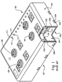
- FIG. 1 illustrates a known industrial automation input output module 100 comprising a housing 102 constructed from inner and outer housing members 102a,102b that are inter-fitted with each other to define an enclosed interior space 104 in which one or more electronic circuit boards 106 is/are located.
- the inner and outer housing members 102a,102b are each preferably defined as one-piece molded polymeric constructions utilizing any of a wide variety of polymeric materials in an injection molding process.
- One suitable material is glass-filled polyester, although it is not intended that the development be limited to such material or any other material.
- One or more connectors 108 are operably connected to the circuit board 106 and project through a top face 110 of the outer housing member 102b so as to be adapted for mating with corresponding cable connectors from external input output devices or the like.
- the circuit boards 106 and connectors 108 are adapted for any desired electrical application such as input and output to/from an industrial process.
- a module 100 typically comprises a plurality of visual indicators such as light emitting diodes operably connected to a circuit board 106 and that provide visual output signals concerning the state of the circuitry 106 in the module 100 and/or flow of data or power or other signals.
- a light pipe includes lenses 114 that are aligned with and/or project through respective openings 116 in the top face 110 of the outer housing member 102b or other location of the housing 102 to communicate light from the LED's outside of the module 100.
- the connectors 108, light pipe lenses 114 and any other openings in the outer housing member 102b are sealed against ingress of water, dirt or other contaminants to the interior space 104 using a potting compound PT that is applied into the outer housing member 102b after the various components such as the connectors and light pipe are installed. Often, multiple layers of potting compound PT are used and installed/cured in stages as components are correspondingly added in stages.
- Potting compound PT is also used to seal the connection between the inner and outer housing members 102a,102b.
- the inner housing member 102a is adapted for nesting within the outer housing member 102b and comprises a plurality of tabs 102T that are received in corresponding recesses 102R such as notches, or apertures defined by the outer housing member 102b so that the housing members 102a,102b are mechanically interlocked with a close snap-fit.
- the inner housing member 102a comprises a continuous peripheral wall 102W projecting outwardly therefrom that is received within a corresponding continuously extending peripheral groove 102G defined by the outer housing member 102b. The joint at the junction of the wall 102W and groove 102G is sealed with the potting compound PT.
- the module 100 of FIG. 1 has various drawbacks relating to the use of potting compound PT to provide the requisite ingress protection. Potted products cannot be disassembled and repaired. A batch of defective modules 100 must be discarded even if only a single component of each module is defective. Assembled modules 100 that are potted cannot be disassembled and reconfigured. The potting compound PT must be cured by passage of time and/or application of heat, neither of which is desirable in a manufacturing system. The potting compound PT is dense and adds significant weight to the product. The presence of potting compound PT also prevents recycling of the module 100.
- US 2006/0082975 A1 discloses an electronic control unit comprising an electronic control enclosure for housing electronic components of the electronic control unit and that is configured to dissipate heat from within the enclosure, while environmentally sealing the electronic components in the electronic control enclosure.
- An object of the invention is to provide an industrial automation input output module that is highly resistant to ingress of contaminants without using a potting compound. This object is solved by the subject matter of independent claim 1. Preferred embodiments are subject matter of the dependent claims.
- an industrial automation input output module includes an outer housing member with a top housing wall and an outer peripheral housing wall.
- the top housing wall and the outer peripheral housing wall define an open recess.
- the outer housing member further includes an inner peripheral housing wall spaced from the outer peripheral housing wall.
- a groove is defined between the inner peripheral housing wall and the outer peripheral housing wall.
- An inner housing member is received in the open recess of the outer housing member so that the inner and outer housing members together define an interior space for containing at least one circuit board.
- the inner housing member includes a projecting seal engagement wall that is received in the groove.
- a one-piece elastomeric main seal is installed adjacent the groove.
- the main seal includes: (i) a lateral seal portion that provides a fluid-tight seal between an inner face of said seal engagement wall and the inner peripheral housing wall; and, (ii) a face seal portion located in the groove that provides a fluid-tight seal between a tip of the seal engagement wall and the outer housing member.
- the industrial automation input output module further includes a visual indicator adjacent a visual indicator opening in the top housing wall.
- the one-piece elastomeric main seal further includes a light-pipe portion including a translucent light pipe adapted to communicate light from a light source located in the interior space of the module to the visual indicator opening.
- an elastomeric seal comprises a one-piece body including a seal portion and a light pipe portion, said seal portion including a plurality of linear segments and a plurality of corners located respectively between the linear segments, wherein the linear segments and the corners define the main seal to have an open central portion.
- the light pipe portion includes a translucent light pipe having an inner end and an outer end, and the light pipe is adapted to communicate light from the inner end to the outer end thereof.
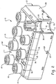
- FIG. 2 shows an industrial automation input output module 10 that corresponds in terms of structure to the module 100 of FIG. 1 , except that the potting compound PT of the module 100 of FIG. 1 is eliminated and replaced with a one-piece elastomeric seal 30 in accordance with the present invention.
- the one or more connectors 18 of the module 10 are sealed to the housing with O-rings or other elastomeric seals, depending on the type of connector.
- the module 10 comprises a housing 12 constructed from inner and outer housing members 12a,12b that are inter-fitted with each other to define an enclosed interior space 14 in which one or more electronic circuit boards 16 is/are located.
- the inner and outer housing members 12a,12b are each preferably defined as one-piece molded polymeric constructions utilizing any of a wide variety of polymeric materials in an injection molding process.
- One suitable material is glass-filled polyester, although it is not intended that the development be limited to such material or any other material.
- the connectors 18 are operably connected to a circuit board 16 and project through a top wall 11 of the outer housing member 12b so as to be adapted for mating with corresponding cable connectors from external input output devices or the like.
- the circuit boards 16 and connectors 18 are adapted for any desired electrical application such as input and output to/from an industrial process.
- the module 10 comprises a plurality of visual indicators 25 that project through corresponding openings 26 in the outer housing member 12b that provide visual output signals concerning the state of the circuitry 16 in the module 10 and/or flow of data or power or other signals.
- the housing member 12 is sealed against ingress of water, dirt or other contaminants using a main elastomeric seal 30 located between the inner and outer housing members 12a,12b, and an elastomeric seal for each connector 18.
- the visual indicators 25 are also sealed relative to the openings 26 in the outer housing member 12b, but remain visible outside of the housing member 12.
- the inner housing member 12a is adapted for nesting within the outer housing member 12b and comprises a plurality of tabs 12T that are received in corresponding recesses 12R such as notches, or apertures defined by the outer housing member 12b so that the housing members 12a,12b are mechanically interlocked with a close snap-fit without requiring use of screws or other fasteners.
- the inner housing member 12a comprises a continuous peripheral wall 12W projecting outwardly therefrom that is received within a corresponding continuously extending peripheral groove 12G defined by the outer housing member 12b.
- the joint at the junction of the wall 12W and groove 12G of the module 10 is sealed with the main elastomeric seal 30 to prevent ingress of water, dirt, and other contaminants at the interface between the wall 12W and groove 12G.
- the wall 12W is sometimes referred to herein as a "seal engagement wall.”
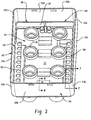
- FIG. 3 shows the outer housing member 12b by itself in an inverted state and with the circuit board(s) 16 and other components removed so that it can be seen that the outer housing member includes an open recess 20 defined by the top wall 11 and a plurality of side walls 22a,22b,22c,22d that project outwardly from the top wall 11 and that are connected to each other by corners 23a,23b,23c,23d so as to define a continuous outer peripheral wall structure 22.
- the connectors 18 project through respective openings 19 in the top wall 11 and are sealed using respective connector seals 70 (see FIG. 8 ).
- the groove 12G is defined between an inner face of the peripheral wall 22 and a correspondingly shaped but shorter second or inner wall 24 that is spaced inward from the peripheral wall 22 (see also FIG. 6 ). As shown in FIG. 6 , this inner wall 24 comprises an outer edge 24a and first and second opposite faces 24b,24c and thus defines a mounting location for the main elastomeric seal 30.
- the main elastomeric seal 30, itself is shown in FIGS. 4A , 4B , and 5 and comprises a one-piece molded elastomeric body defined from a suitable elastomer such as DuPontTM Vamac® ethylene acrylic elastomer (AEM) or a commercial grade silicone or any other compressible, resilient elastomeric composition suitable for seals (that is preferably also clear or at least translucent for light piping capability as disclosed below).
- the seal 30 is dimensioned and conformed so as to be adapted to seal the groove 12G of the outer housing member 12b, i.e., to seal the space between the seal engaging wall 12W of the inner housing member 12a and the groove 12G of the outer housing member 12b.
- the seal 30 defines an overall rectangular shape comprising four linear segments 32a,32b,32c,32d connected by corners 33a,33b,33c,33d.
- the linear segments 32a-32d and corners 33a-33d preferably define an open central portion O of the seal 30 therebetween to reduce material usage and to minimize the likelihood that the seal 30 will interfere with other components of the module 10, e.g., the connectors 18.
- the linear segments 32a-32d and corners 33a,33d are defined by spaced apart inner and outer walls 34a,34b that are interconnected by an end wall 34c, wherein the inner and outer walls 34a,34b and end wall 34c define a U-shaped wall receiving structure adapted for close sliding receipt of the inner wall 24 of the outer housing member 12b as shown in FIG. 6 , with the interface between the housing wall 24 and the seal walls 34a,34b being smooth and planar over at least a substantial portion of both opposite faces 24a,24b of the wall 24.
- the outer seal wall 34b located adjacent the groove 12G, comprises an outer face 36 that provides a lateral seal portion SL.
- This outer face 36 preferably defines one or more sealing ribs 36r that extend parallel to the outer and inner walls 22,24 and parallel to the groove 12G.
- the sealing ribs 36r preferably define a saw-tooth cross-section, with a ramp surface 36a that diverges from the seal wall 34b as it extends away from the end wall 34c, which facilitates insertion of the seal engagement wall 12W of the inner housing member into the groove 12G when the module 10 is assembled and which also tends to improve sealing in response to any fluid pressure being exerted on the ribs 36r toward the interior space 14 of the module 10.
- the sealing ribs 36r engage and are compressed by an inner surface 12Wi of the wall 12W when the wall 12W is inserted in the groove 12G as shown in FIG. 7 .
- the seal 30 further comprises a face seal portion SF defined by a lip 38 that projects transversely outward from the seal outer wall 34b away from the inner wall 34a at a location spaced from the end wall 34c so as to be located in the groove 12G, in abutment with an inner wall 12Gi of the groove that extends between and interconnects the walls 22,24 of the outer housing member 12b.
- the lip 38 of the face seal portion SF defines an outwardly facing recess 38r that opens upwardly away from the inner wall 12Gi of the groove 12G so as to be adapted for receipt of a tip 12Wt of the wall 12W of the inner housing portion 12a when the inner and outer housing portions 12a,12b are inter-fitted to define the module housing 12 as shown in FIG. 7 .
- the lip 38 At least at each of the corners 33a-33d of the seal, the lip 38 further comprises an upwardly projecting tab 38t that projects upwardly away from the recess 38r at a location spaced from the seal outer wall 34b.
- the seal engagement wall 12W of the inner housing member 12a is received between the seal outer wall 34b and each tab 38t, and the tabs 38t ensure a fluid-tight seal between the corners 23a,23b,23c,23d of the outer housing wall 22 and the corresponding adjacent corners of the seal engagement wall 12W of the inner housing 12a when the inner housing 12a is installed in the outer housing 12b.
- the tabs 38t ensure a fluid-tight seal at the corners 23a-23d which can otherwise be prone to leaks.
- the main elastomeric seal 30 preferably includes at least one integral light-pipe portion 50 as part of its one-piece construction.
- the light pipe portion 50 is defined as part of the one-piece seal construction from the same material and comprises at least one light pipe 52 which is transparent or at least translucent, depending upon the material from which the seal 30 is defined.
- a base wall 54 is connected to the seal inner wall 34a and extends transversely inward toward a center of the seal 30, and each light pipe 52 is connected to the base wall 54.
- the seal 30 comprises two light pipe portions 50a,50b of like construction located on opposite sides of the seal opening O, each comprising a plurality of light pipes 52.
- Each light pipe 52 is adapted to communicate light from a light source such as an LED or other light source located inside the space 14 of the module 10 to a location adjacent one of the visual indicator openings 26 of the outer housing member 12b. More particularly, as shown in FIG. 7 , each light pipe 52 comprises an inner end 52a and an outer end 52b. The inner end 52a is adapted to be positioned in abutment with or otherwise adjacent an LED or other light source 56 connected to a circuit board 16 or other location in the module 10.
- a light source such as an LED or other light source located inside the space 14 of the module 10 to a location adjacent one of the visual indicator openings 26 of the outer housing member 12b. More particularly, as shown in FIG. 7 , each light pipe 52 comprises an inner end 52a and an outer end 52b. The inner end 52a is adapted to be positioned in abutment with or otherwise adjacent an LED or other light source 56 connected to a circuit board 16 or other location in the module 10.
- each visual indicator opening 26 is surrounded by a respective visual indicator boss 26b that is part of the outer housing member 12b and that includes a cylindrical inner surface.
- the outer end 52b of each light pipe comprises one or more radically projecting scaling ribs 57 that engage the corresponding visual indicator boss 26b with a fluid-tight fit as shown in FIG. 7 (note that in FIG.
- each light pipe 52 comprise a hollow tube structure including a bore 53 closed at the outer end 52b but otherwise open from the closed end 52b to and through the inner end 52a.
- the open, tubular bore 53 of the light pipe maximizes communication of light from the light source 54 to the closed outer end 52b of the light pipe, whereas a solid mass of the elastomeric seal material would lead to light losses, scattering and/or dissipation.
- the bore 53 also facilitates injection molding of the one-piece main seal 30.
- the main seal 30, including the light pipe portion 50 can alternatively be made integral to the outer housing member 12b using a transfer or insert molding process, in which the main seal 30 becomes permanently bonded to and/or defined as part of the outer housing member 12b.
- each connector 18 projects through respective openings 19 in the outer housing member 12b as shown in FIGS 2 and 3 .
- each connector 18 must be sealingly engaged with the outer housing member 12b to prevent ingress of water and other contaminants to the interior space 14 between the connector 18 and outer housing member 12b as required by the IP65/IP67 or other comparable standard.
- each connector 18 is sealed to the outer housing member 12b using an O-ring or like seal 70 as shown in FIG. 8 .
- the top wall 11 of the outer housing member 12b includes one or more connector mounting locations 60 corresponding in number to the number of connectors 18 for the module 10.
- Each connector mounting location 60 is defined by a connector opening 19 in the top wall 11, an outer boss 62 that projects from an outer surface 11a of the top wall and that encircles the opening 19, and an inner boss 64 that also encircles the opening 19 but projects from an opposite inner surface 11b of the top wall 11 into the open recess 20 of the outer housing member 12b.
- the outer and inner bosses 62,64 each comprise a cylindrical inner surface.
- the connector 18 is inserted into the connector mounting location 60, from inside the open recess 20 of the outer housing member 12b, so that the connector extends through the opening 19 with an outer portion 18a of the connector tightly fit into the outer boss 62 and an inner portion 18b of the connector tightly fit into the inner boss 64.
- the inner portion 18b of the connector comprises an elastomeric O-ring seal 70 seated in a circumferential groove 72, and the seal 70 engages the inner boss 64 with a fluid-tight fit.
- the connectors 18 are typically metallic and can be any of a wide variety of well known connectors. As shown, the connectors 18 adapted for threaded connection with a mating cable connector and, as such, each comprise an internally threaded portion 18t.
- each connector 18 includes means for preventing rotation of the connector relative to the connector mounting location 60.
- the outer portion 18a of each connector includes a plurality of vertical or otherwise configured ribs 18r so that a knurled outer surface is defined which frictionally engages the outer cylindrical boss 62 to inhibit rotation of the connector 18. It is preferred that the knurled outer surface defined by the ribs 18r be bonded to the outer cylindrical boss, e.g., by ultrasonic welding or an adhesive or the like.
Landscapes
- Engineering & Computer Science (AREA)
- Microelectronics & Electronic Packaging (AREA)
- General Engineering & Computer Science (AREA)
- Mechanical Engineering (AREA)
- Casings For Electric Apparatus (AREA)
- Arrangement Of Elements, Cooling, Sealing, Or The Like Of Lighting Devices (AREA)
- Gasket Seals (AREA)
- Connector Housings Or Holding Contact Members (AREA)
Claims (14)
- Automatisches Industrie-Eingabe-Ausgabe-Modul, das umfasst:ein äußeres Gehäuseelement (12b), das eine obere Gehäusewand (11) und eine äußere Umfangsgehäusewand (22) umfasst,ein inneres Gehäuseelement (12a), wobei das innere Gehäuseelement (12a) angepasst ist, um in dem äußeren Gehäuseelement (12b) verschachtelt zu werden und eine Vielzahl von Laschen (12T) umfasst, die in entsprechenden Aussparungen (12R) aufgenommen werden, die durch das äußere Gehäuseelement (12b) definiert werden, so dass das innere Gehäuseelement (12a) und das äußere Gehäuseelement (12b) mit einem engen Schnappverschluss mechanisch verhakt sind; undeine einstückige Elastomer-Hauptdichtung (30),dadurch gekennzeichnet, dassdie obere Gehäusewand (11) und die äußere Umfangsgehäusewand (22) eine offene Aussparung (20) definieren, wobei das äußere Gehäuseelement (12b) des Weiteren eine innere Umfangsgehäusewand (24) umfasst, die von der äußeren Umfangsgehäusewand (22) beabstandet ist, wobei eine Nut (12G) zwischen der inneren Umfangsgehäusewand (24) und der äußeren Umfangsgehäusewand (22) definiert ist;das innere Gehäuseelement (12a) in der offenen Aussparung (20) des äußeren Gehäuseelements (12B) aufgenommen wird, so dass das innere (12a) und das äußere Gehäuseelement (12b) zusammen einen inneren Raum definieren, um wenigstens eine Leiterplatte (16) zu beinhalten, wobei das innere Gehäuseelement (12a) eine vorstehende Dichtungseingriffswand (12W) umfasst, die in der Nut (12G) aufgenommen wird; unddie einstückige Elastomer-Hauptdichtung (30) angrenzend an der Nut (12G) eingebaut ist, wobei die Hauptdichtung (30) umfasst:eine innere Dichtungswand (34a), eine äußere Dichtungswand (34b) und eine Dichtungsstirnwand (34c), die einen U-förmigen Wandaufnahmeaufbau definieren, der für ein enge gleitende Aufnahme der inneren Umfangsgehäusewand (24) des äußeren Gehäuseelements (12b) angepasst ist,wobei dadurch die angrenzend an der Nut (12G) angeordnete-äußere Dichtungswand (34b) eine Außenfläche (36) umfasst, die ein fluiddichtes seitliches Dichtungsteil (SL) zwischen einer Innenfläche (12Wi) der Dichtungseingriffswand (12W) und der inneren Umfangsgehäusewand (24) bereitstellt; unddie Dichtung (30) des Weiteren ein Flächendichtungsteil (SF) umfasst, das durch eine Lippe (38) definiert wird, die von der äußeren Dichtungswand (34b) von der inneren Dichtungswand (34a) weg an einer Stelle quer nach außen vorsteht, die von der Dichtungsstirnwand (34c) beabstandet ist, so dass sie in der Nut (12G) in Anschlag mit einer Innenwand (12Gi) der Nut angeordnet ist, die sich zwischen den inneren und äußeren Umfangswänden (24, 22) des äußeren Gehäuseelements (12b) erstreckt und sie miteinander verbindet, wobei dadurch eine fluiddichte Abdichtung zwischen einer Spitze (12Wt) der Dichtungseingriffswand (12W) und dem äußeren Gehäuseelement (12b) bereitgestellt wird.
- Automatisches Industrie-Eingabe-Ausgabe-Modul nach Anspruch 1, das des Weiteren umfasst:eine Verbinder-Montagestelle (60) mit einer Verbinderöffnung (19), die in der oberen Gehäusewand (11) definiert ist;einen Verbinder (18), der in der Verbinderöffnung (19) eingebaut ist; undeine elastomere Verbinderdichtung (70), die eine fluiddichte Abdichtung zwischen dem Verbinder (18) und dem äußeren Gehäuseelement (12b) bereitstellt.
- Automatisches Industrie-Eingabe-Ausgabe-Modul nach Anspruch 2, wobei die Verbinder-Montagestelle (60) des Weiteren einen inneren Vorsprung (64) umfasst, der von einer inneren Seite (11 b) der oberen Gehäusewand (11) vorsteht und der die Verbinderöffnung (19) umgibt, wobei der Verbinder (18) ein inneres Teil (18b) mit einer in einer Nut (72) eingesetzten elastomeren Abdichtung (70) aufweist, wobei die Dichtung (70) sowohl mit dem inneren Verbinderteil (18b) als auch mit dem zylindrischen Vorsprung (64) in Eingriff steht, um eine fluiddichte Abdichtung bereitzustellen.
- Automatisches Industrie-Eingabe-Ausgabe-Modul nach Anspruch 3, wobei die Verbinder-Montagestelle (60) des Weiteren einen äußeren Vorsprung (62) umfasst, der von einer äußeren Seite (11a) der oberen Gehäusewand (11) vorsteht und der das Verbinderöffnungsteil (19) umgibt, wobei der Verbinder (18) ein äußeres Teil (18a) umfasst, das mit dem äußeren Vorsprung (62) in Reibungseingriff steht, um eine Drehung des Verbinders (18) relativ zum äußeren Vorsprung (62) zu verhindern.
- Automatisches Industrie-Eingabe-Ausgabe-Modul nach Anspruch 4, wobei das äußere Teil (18a) des Verbinders (18) eine gerändelte Oberfläche umfasst, die mit dem äußeren zylindrischen Vorsprung (62) verbunden ist.
- Automatisches Industrie-Eingabe-Ausgabe-Modul nach einem der Ansprüche 1 bis 5, wobei die einstückige elastomere Hauptdichtung (30) eine Vielzahl von linearen Segmenten (32a - 32d) und eine Vielzahl von Ecken (33a - 33d) umfasst, die sich jeweils zwischen den linearen Segmenten (32a - 32d) befinden, wobei die linearen Segmente (32a - 32d) und die Ecken (33a - 33d) die Hauptdichtung (30) definieren, um ein offenes mittleres Teil aufzuweisen.
- Automatisches Industrie-Eingabe-Ausgabe-Modul nach Anspruch 6, wobei die linearen Segmente (32a - 32d) die innere Dichtungswand (34a), die äußere Dichtungswand (34b) und die Dichtungsstirnwand (34c) umfassen.
- Automatisches Industrie-Eingabe-Ausgabe-Modul nach Anspruch 7, wobei die äußere Dichtungswand (34b) wenigstens eine Dichtungsrippe (36r) umfasst, die sich parallel zur Nut (12G) erstreckt.
- Automatisches Industrie-Eingabe-Ausgabe-Modul nach Anspruch 8, wobei die Dichtungsrippe (36r) einen Sägezahn-Querschnitt mit einer Auflauffläche (36a) definiert, der von der äußeren Dichtungswand (34b) divergiert, wenn es sich von der Dichtungsstirnwand (34c) weg erstreckt.
- Automatisches Industrie-Eingabe-Ausgabe-Modul nach Anspruch 7, wobei die Lippe (38) eine Aussparung (38r) umfasst, die sich nach oben von der Innenwand (12Gi) der Nut (12G) weg öffnet.
- Automatisches Industrie-Eingabe-Ausgabe-Modul nach Anspruch 7, wobei die Lippe (38) eine Vielzahl von Laschen (38t) umfasst, die von dort nach außen vorstehen und sich jeweils an der Vielzahl von Ecken (33a - 33d) befinden, die von der äußeren Dichtungswand (34b) beabstandet sind, wobei sich die Dichtungseingriffswand (12W) des inneren Gehäuseelement (12a) zwischen der äußeren Dichtungswand (34b) und den Laschen (38t) befindet.
- Automatisches Industrie-Eingabe-Ausgabe-Modul nach Anspruch 1, das des Weiteren eine visuelle Anzeige (25) angrenzend an einer visuellen Anzeigeöffnung (26) in der oberen Gehäusewand (11) umfasst, wobei die einstückige Elastomer-Hauptdichtung (30) des Weiteren umfasst:ein Lichtleiterteil (50), das einen durchscheinenden Lichtleiter (52) umfasst, der angepasst ist, um Licht von einer Lichtquelle (56), die sich in dem inneren Raum (14) des Moduls (14) befindet, zu der visuellen Anzeigeöffnung (26) zu kommunizieren.
- Automatisches Industrie-Eingabe-Ausgabe-Modul nach Anspruch 12, wobei der Lichtleiter (52) ein inneres Ende (52a), das angrenzend an der Lichtquelle (56) angeordnet ist, und ein äußeres Ende (52b) umfasst, das angrenzend an der visuellen Anzeigeöffnung (26) angeordnet ist, wobei das äußere Ende (52b) des Lichtleiters (52) durch die visuelle Anzeigeöffnung (26) vorsteht, um die visuelle Anzeige (25) zu bilden, wobei der Lichtleiter (52) mit dem äußeren Gehäuseelement (12b) abdichtend in Eingriff steht, um ein Eindringen von Fluid in den inneren Raum (14) zwischen dem Lichtleiter (52) und dem äußeren Gehäuseelement (12b) zu verhindern, und wobei der Lichtleiter (52) einen hohlen, röhrenförmigen Aufbau mit einer Bohrung (53) umfasst, die sich von dem und durch das innere Ende (52a) zum äußeren Ende (52b) erstreckt, wobei das äußere Ende (52b) der Bohrung (53) verschlossen ist.
- Automatisches Industrie-Eingabe-Ausgabe-Modul nach Anspruch 12, wobei der Lichtleiter (52) ein inneres Ende (52a), das angrenzend an der Lichtquelle (56) angeordnet ist, und ein äußeres Ende (52b) umfasst, das angrenzend an der visuellen Anzeigeöffnung (26) angeordnet ist, um die visuelle Anzeige (25) zu definieren, und wobei das äußere Gehäuseelement (12b) einen visuellen Anzeige-Vorsprung (26b) umfasst, der die visuelle Anzeigeöffnung (26) umgibt, und wobei das äußere Ende (52b) des Lichtleiters (52) eine Dichtungsrippe (57) umfasst, die von dort nach außen vorsteht und die mit dem visuellen Anzeige-Vorsprung (26b) mit einer fluiddichten Abdichtung in Eingriff steht.
Applications Claiming Priority (1)
| Application Number | Priority Date | Filing Date | Title |
|---|---|---|---|
| US11/824,987 US7503790B2 (en) | 2007-07-03 | 2007-07-03 | Industrial automation input output module with elastomeric sealing |
Publications (3)
| Publication Number | Publication Date |
|---|---|
| EP2012573A2 EP2012573A2 (de) | 2009-01-07 |
| EP2012573A3 EP2012573A3 (de) | 2009-02-25 |
| EP2012573B1 true EP2012573B1 (de) | 2017-06-21 |
Family
ID=39739367
Family Applications (1)
| Application Number | Title | Priority Date | Filing Date |
|---|---|---|---|
| EP08159623.1A Ceased EP2012573B1 (de) | 2007-07-03 | 2008-07-03 | Automatisches Industrie-Eingabe-Ausgabe-Modul mit Elastomerdichtung |
Country Status (2)
| Country | Link |
|---|---|
| US (2) | US7503790B2 (de) |
| EP (1) | EP2012573B1 (de) |
Families Citing this family (17)
| Publication number | Priority date | Publication date | Assignee | Title |
|---|---|---|---|---|
| TWI333805B (en) | 2003-10-03 | 2010-11-21 | Osram Sylvania Inc | Housing for electronic ballast |
| DE102009005716B4 (de) | 2009-01-22 | 2014-01-02 | Rittal Gmbh & Co. Kg | Gehäuse |
| US20110254030A1 (en) * | 2010-04-15 | 2011-10-20 | Perkinelmer Elcos Gmbh | Liquid reflector |
| CN201781111U (zh) * | 2010-07-22 | 2011-03-30 | 美国莫列斯股份有限公司 | 电连接器及其组件 |
| US9974952B2 (en) | 2010-12-17 | 2018-05-22 | Advanced Bionics Ag | Sound processor housings, sound processors and implantable cochlear stimulation systems including the same |
| CN103270620B (zh) | 2010-12-17 | 2015-11-25 | 领先仿生公司 | 声音处理器外壳,声音处理器和包括声音处理器的可植入耳蜗刺激系统 |
| US8965019B2 (en) | 2010-12-17 | 2015-02-24 | Advanced Bionics Ag | Sound processor housings, sound processors and implantable cochlear stimulation systems including the same |
| US8965020B2 (en) | 2010-12-17 | 2015-02-24 | Advanced Bionics Ag | Sound processors with light transmissive seals and implantable cochlear stimulation systems including the same |
| DK177658B1 (en) * | 2011-12-16 | 2014-02-03 | Envision Energy Denmark Aps | A wind turbine nacelle cover and a method for installing a generator on a mainframe in a nacelle |
| JP6023454B2 (ja) * | 2012-04-11 | 2016-11-09 | 東光東芝メーターシステムズ株式会社 | 電力量計 |
| US8757847B2 (en) * | 2012-06-29 | 2014-06-24 | Eaton Corporation | Pedestal light assembly |
| DE102013100987B4 (de) | 2013-01-31 | 2023-06-29 | Phoenix Contact Gmbh & Co. Kg | Anschlussmodul |
| US20190097362A1 (en) * | 2017-09-26 | 2019-03-28 | Xcelsis Corporation | Configurable smart object system with standard connectors for adding artificial intelligence to appliances, vehicles, and devices |
| US11167433B2 (en) * | 2018-10-02 | 2021-11-09 | Flexiv Ltd. | Sealing apparatus and articulated robot |
| USD918149S1 (en) | 2019-01-09 | 2021-05-04 | Wago Verwaltungsgesellschaft Mbh | Control device |
| USD929348S1 (en) * | 2019-03-25 | 2021-08-31 | Rittal Gmbh & Co. Kg | Housing of switchboard for electric connections |
| TWI854806B (zh) * | 2023-08-29 | 2024-09-01 | 香港商埃爾加托艾迪斯普雷有限公司 | 可調整更換的模組化控制面板 |
Family Cites Families (21)
| Publication number | Priority date | Publication date | Assignee | Title |
|---|---|---|---|---|
| US4335273A (en) * | 1979-05-25 | 1982-06-15 | Electric Power Research Institute, Inc. | Electrically insulating seal assembly |
| DE3815511A1 (de) * | 1988-05-06 | 1989-11-16 | Daimler Benz Ag | Gummielastische abdichtung zwischen zwei loesbaren gehaeuseteilen, insbesondere solche zwischen einer oelwanne und einem getriebegehaeuse fuer einen fahrzeugantrieb |
| DE4223322C1 (de) * | 1992-07-16 | 1993-07-29 | Schroff Gmbh, 7541 Straubenhardt, De | |
| US5277610A (en) * | 1992-12-21 | 1994-01-11 | Molex Incorporated | Sealing system for electrical connectors |
| JP3156494B2 (ja) * | 1994-04-01 | 2001-04-16 | セイコーエプソン株式会社 | デジタルマルチメータ |
| JPH09116277A (ja) * | 1995-10-18 | 1997-05-02 | Yazaki Corp | 電気接続箱 |
| JPH10241783A (ja) * | 1997-02-28 | 1998-09-11 | Yazaki Corp | パッキンの固定方法及びパッキンの固定構造 |
| US6231052B1 (en) * | 1999-10-26 | 2001-05-15 | W. Thomas Forlander | Transparent flange protector |
| JP3478385B2 (ja) * | 2000-05-11 | 2003-12-15 | 住友電装株式会社 | 防水コネクタ |
| DE10151413B4 (de) * | 2001-10-18 | 2005-05-19 | Siemens Ag | Dichtung zum Abdichten eines Spaltes zwischen zwei abzudichtenden Gehäuseteilen, sowie ein Gehäuse eines Steuergerätes eines Kraftfahrzeugs |
| US6881101B2 (en) | 2003-02-20 | 2005-04-19 | Rockwell Automation Technologies, Inc. | Modular electrical device |
| WO2004075356A1 (en) | 2003-02-20 | 2004-09-02 | Rockwell Automation Technologies, Inc. | Modular electrical device |
| TWI333805B (en) * | 2003-10-03 | 2010-11-21 | Osram Sylvania Inc | Housing for electronic ballast |
| EP1706666A4 (de) * | 2003-12-16 | 2007-03-28 | 1662801 Ontario Inc | Beleuchtungsanordnung, kühlkörper und wärmerückgewinnungssystem dafür |
| US7190589B2 (en) | 2004-10-19 | 2007-03-13 | Cinch Connectors, Inc. | Electronic control enclosure |
| US20060292913A1 (en) * | 2005-06-23 | 2006-12-28 | Siemens Vdo Automotive Corporation | Integrated direct fuel pump connector |
| TWM286471U (en) * | 2005-09-09 | 2006-01-21 | Smart Ant Telecom Co Ltd | Waterproof housing |
| US7572027B2 (en) * | 2005-09-15 | 2009-08-11 | Integrated Illumination Systems, Inc. | Interconnection arrangement having mortise and tenon connection features |
| EA014861B1 (ru) * | 2006-05-30 | 2011-02-28 | Необульб Текнолоджиз Инк. | Светодиодное осветительное оборудование высокой мощности с высокой эффективностью теплоотвода |
| US7329030B1 (en) * | 2006-08-17 | 2008-02-12 | Augux., Ltd. | Assembling structure for LED road lamp and heat dissipating module |
| WO2008070519A2 (en) * | 2006-12-01 | 2008-06-12 | Abl Ip Holding Llc | Systems and methods for thermal management of lamps and luminaires using led sources |
-
2007
- 2007-07-03 US US11/824,987 patent/US7503790B2/en active Active
-
2008
- 2008-07-03 EP EP08159623.1A patent/EP2012573B1/de not_active Ceased
-
2009
- 2009-02-18 US US12/372,806 patent/US8115099B2/en active Active
Non-Patent Citations (1)
| Title |
|---|
| None * |
Also Published As
| Publication number | Publication date |
|---|---|
| EP2012573A3 (de) | 2009-02-25 |
| US20090152821A1 (en) | 2009-06-18 |
| EP2012573A2 (de) | 2009-01-07 |
| US8115099B2 (en) | 2012-02-14 |
| US20090008880A1 (en) | 2009-01-08 |
| US7503790B2 (en) | 2009-03-17 |
Similar Documents
| Publication | Publication Date | Title |
|---|---|---|
| EP2012573B1 (de) | Automatisches Industrie-Eingabe-Ausgabe-Modul mit Elastomerdichtung | |
| US10139098B2 (en) | Sealed LED light module | |
| US6881101B2 (en) | Modular electrical device | |
| US7755907B2 (en) | Electronic control device | |
| WO2004053375A3 (en) | Pipe fitting with composite gasket assembly | |
| JP6763222B2 (ja) | 多光軸光電センサ | |
| US6045140A (en) | Retention gasket with cooperating cover | |
| CA2429774C (en) | Housings for circuit cards | |
| JP7393402B2 (ja) | 端子台 | |
| JP6750648B2 (ja) | 防爆構造 | |
| EP1884707A2 (de) | Wasserdichtes Beleuchtungsgerät mit bündiger Anbringung | |
| EP3642536B1 (de) | Kostengünstige, kompakte abdichtung für seitenausgangskabel für ip66-led-aussenbereichsmodule | |
| US11761621B2 (en) | Method for forming a luminaire | |
| US10090655B1 (en) | Universal inlet conduit box and method for coupling a sensor to cables | |
| CN108807736A (zh) | 一种防水结构组件及水上动力装备 | |
| KR100913858B1 (ko) | 케이블 진입부 또는 파이프 관통부용 하나 이상의 탄성 모듈을 포함하는 프레임 및 방법 | |
| EP0134155B1 (de) | Wärmeübertragungsplatte | |
| US20210016268A1 (en) | Fluid guiding module and fluid guiding system having at least two fluid guiding modules | |
| JPH11257533A (ja) | 電磁弁 | |
| RU2630604C2 (ru) | Крышка для канального датчика | |
| CN101692564A (zh) | 连接盒和包括这类盒的连接组件 | |
| JP2005127520A (ja) | 密封装置 | |
| CN222638268U (zh) | 一种带密封结构的智能驱动同步电动机 | |
| JP2009049215A (ja) | 密封筐体 | |
| KR102850341B1 (ko) | 밀폐형 커넥터 조립체 |
Legal Events
| Date | Code | Title | Description |
|---|---|---|---|
| PUAI | Public reference made under article 153(3) epc to a published international application that has entered the european phase |
Free format text: ORIGINAL CODE: 0009012 |
|
| AK | Designated contracting states |
Kind code of ref document: A2 Designated state(s): AT BE BG CH CY CZ DE DK EE ES FI FR GB GR HR HU IE IS IT LI LT LU LV MC MT NL NO PL PT RO SE SI SK TR |
|
| AX | Request for extension of the european patent |
Extension state: AL BA MK RS |
|
| PUAL | Search report despatched |
Free format text: ORIGINAL CODE: 0009013 |
|
| AK | Designated contracting states |
Kind code of ref document: A3 Designated state(s): AT BE BG CH CY CZ DE DK EE ES FI FR GB GR HR HU IE IS IT LI LT LU LV MC MT NL NO PL PT RO SE SI SK TR |
|
| AX | Request for extension of the european patent |
Extension state: AL BA MK RS |
|
| 17P | Request for examination filed |
Effective date: 20090814 |
|
| AKX | Designation fees paid |
Designated state(s): DE FR GB |
|
| 17Q | First examination report despatched |
Effective date: 20091022 |
|
| RAP1 | Party data changed (applicant data changed or rights of an application transferred) |
Owner name: ROCKWELL AUTOMATION ASIA PACIFIC BUSINESS CTR. PTE |
|
| REG | Reference to a national code |
Ref country code: DE Ref legal event code: R079 Ref document number: 602008050735 Country of ref document: DE Free format text: PREVIOUS MAIN CLASS: H05K0005060000 Ipc: F16J0015060000 |
|
| RIC1 | Information provided on ipc code assigned before grant |
Ipc: F16J 15/06 20060101AFI20170131BHEP Ipc: H05K 5/06 20060101ALI20170131BHEP |
|
| GRAP | Despatch of communication of intention to grant a patent |
Free format text: ORIGINAL CODE: EPIDOSNIGR1 |
|
| INTG | Intention to grant announced |
Effective date: 20170317 |
|
| GRAS | Grant fee paid |
Free format text: ORIGINAL CODE: EPIDOSNIGR3 |
|
| GRAA | (expected) grant |
Free format text: ORIGINAL CODE: 0009210 |
|
| AK | Designated contracting states |
Kind code of ref document: B1 Designated state(s): DE FR GB |
|
| REG | Reference to a national code |
Ref country code: GB Ref legal event code: FG4D |
|
| REG | Reference to a national code |
Ref country code: FR Ref legal event code: PLFP Year of fee payment: 10 |
|
| REG | Reference to a national code |
Ref country code: DE Ref legal event code: R096 Ref document number: 602008050735 Country of ref document: DE |
|
| REG | Reference to a national code |
Ref country code: DE Ref legal event code: R097 Ref document number: 602008050735 Country of ref document: DE |
|
| PLBE | No opposition filed within time limit |
Free format text: ORIGINAL CODE: 0009261 |
|
| STAA | Information on the status of an ep patent application or granted ep patent |
Free format text: STATUS: NO OPPOSITION FILED WITHIN TIME LIMIT |
|
| 26N | No opposition filed |
Effective date: 20180322 |
|
| REG | Reference to a national code |
Ref country code: FR Ref legal event code: PLFP Year of fee payment: 11 |
|
| P01 | Opt-out of the competence of the unified patent court (upc) registered |
Effective date: 20230404 |
|
| PGFP | Annual fee paid to national office [announced via postgrant information from national office to epo] |
Ref country code: GB Payment date: 20240620 Year of fee payment: 17 |
|
| PGFP | Annual fee paid to national office [announced via postgrant information from national office to epo] |
Ref country code: FR Payment date: 20240619 Year of fee payment: 17 |
|
| PGFP | Annual fee paid to national office [announced via postgrant information from national office to epo] |
Ref country code: DE Payment date: 20240619 Year of fee payment: 17 |
|
| REG | Reference to a national code |
Ref country code: DE Ref legal event code: R119 Ref document number: 602008050735 Country of ref document: DE |
|
| GBPC | Gb: european patent ceased through non-payment of renewal fee |
Effective date: 20250703 |
|
| PG25 | Lapsed in a contracting state [announced via postgrant information from national office to epo] |
Ref country code: GB Free format text: LAPSE BECAUSE OF NON-PAYMENT OF DUE FEES Effective date: 20250703 |
|
| PG25 | Lapsed in a contracting state [announced via postgrant information from national office to epo] |
Ref country code: DE Free format text: LAPSE BECAUSE OF NON-PAYMENT OF DUE FEES Effective date: 20260203 |
|
| PG25 | Lapsed in a contracting state [announced via postgrant information from national office to epo] |
Ref country code: FR Free format text: LAPSE BECAUSE OF NON-PAYMENT OF DUE FEES Effective date: 20250731 |