EP2012177A1 - Rückbeleuchtungsmodul und Anzeigevorrichtung damit - Google Patents
Rückbeleuchtungsmodul und Anzeigevorrichtung damit Download PDFInfo
- Publication number
- EP2012177A1 EP2012177A1 EP08008124A EP08008124A EP2012177A1 EP 2012177 A1 EP2012177 A1 EP 2012177A1 EP 08008124 A EP08008124 A EP 08008124A EP 08008124 A EP08008124 A EP 08008124A EP 2012177 A1 EP2012177 A1 EP 2012177A1
- Authority
- EP
- European Patent Office
- Prior art keywords
- circuit board
- control circuit
- backlight module
- back bezel
- light
- Prior art date
- Legal status (The legal status is an assumption and is not a legal conclusion. Google has not performed a legal analysis and makes no representation as to the accuracy of the status listed.)
- Withdrawn
Links
- 239000012788 optical film Substances 0.000 claims description 6
- 238000004519 manufacturing process Methods 0.000 description 5
- 230000008901 benefit Effects 0.000 description 4
- 238000009434 installation Methods 0.000 description 4
- 238000012986 modification Methods 0.000 description 4
- 230000004048 modification Effects 0.000 description 4
- 238000001514 detection method Methods 0.000 description 2
- 238000012423 maintenance Methods 0.000 description 2
- 230000008878 coupling Effects 0.000 description 1
- 238000010168 coupling process Methods 0.000 description 1
- 238000005859 coupling reaction Methods 0.000 description 1
- 230000017525 heat dissipation Effects 0.000 description 1
- 239000004973 liquid crystal related substance Substances 0.000 description 1
Images



Classifications
-
- G—PHYSICS
- G02—OPTICS
- G02F—OPTICAL DEVICES OR ARRANGEMENTS FOR THE CONTROL OF LIGHT BY MODIFICATION OF THE OPTICAL PROPERTIES OF THE MEDIA OF THE ELEMENTS INVOLVED THEREIN; NON-LINEAR OPTICS; FREQUENCY-CHANGING OF LIGHT; OPTICAL LOGIC ELEMENTS; OPTICAL ANALOGUE/DIGITAL CONVERTERS
- G02F1/00—Devices or arrangements for the control of the intensity, colour, phase, polarisation or direction of light arriving from an independent light source, e.g. switching, gating or modulating; Non-linear optics
- G02F1/01—Devices or arrangements for the control of the intensity, colour, phase, polarisation or direction of light arriving from an independent light source, e.g. switching, gating or modulating; Non-linear optics for the control of the intensity, phase, polarisation or colour
- G02F1/13—Devices or arrangements for the control of the intensity, colour, phase, polarisation or direction of light arriving from an independent light source, e.g. switching, gating or modulating; Non-linear optics for the control of the intensity, phase, polarisation or colour based on liquid crystals, e.g. single liquid crystal display cells
- G02F1/133—Constructional arrangements; Operation of liquid crystal cells; Circuit arrangements
- G02F1/1333—Constructional arrangements; Manufacturing methods
- G02F1/1335—Structural association of cells with optical devices, e.g. polarisers or reflectors
- G02F1/1336—Illuminating devices
- G02F1/133602—Direct backlight
- G02F1/133608—Direct backlight including particular frames or supporting means
-
- G—PHYSICS
- G02—OPTICS
- G02F—OPTICAL DEVICES OR ARRANGEMENTS FOR THE CONTROL OF LIGHT BY MODIFICATION OF THE OPTICAL PROPERTIES OF THE MEDIA OF THE ELEMENTS INVOLVED THEREIN; NON-LINEAR OPTICS; FREQUENCY-CHANGING OF LIGHT; OPTICAL LOGIC ELEMENTS; OPTICAL ANALOGUE/DIGITAL CONVERTERS
- G02F1/00—Devices or arrangements for the control of the intensity, colour, phase, polarisation or direction of light arriving from an independent light source, e.g. switching, gating or modulating; Non-linear optics
- G02F1/01—Devices or arrangements for the control of the intensity, colour, phase, polarisation or direction of light arriving from an independent light source, e.g. switching, gating or modulating; Non-linear optics for the control of the intensity, phase, polarisation or colour
- G02F1/13—Devices or arrangements for the control of the intensity, colour, phase, polarisation or direction of light arriving from an independent light source, e.g. switching, gating or modulating; Non-linear optics for the control of the intensity, phase, polarisation or colour based on liquid crystals, e.g. single liquid crystal display cells
- G02F1/133—Constructional arrangements; Operation of liquid crystal cells; Circuit arrangements
- G02F1/1333—Constructional arrangements; Manufacturing methods
- G02F1/1335—Structural association of cells with optical devices, e.g. polarisers or reflectors
- G02F1/1336—Illuminating devices
- G02F1/133602—Direct backlight
- G02F1/133612—Electrical details
-
- G—PHYSICS
- G02—OPTICS
- G02F—OPTICAL DEVICES OR ARRANGEMENTS FOR THE CONTROL OF LIGHT BY MODIFICATION OF THE OPTICAL PROPERTIES OF THE MEDIA OF THE ELEMENTS INVOLVED THEREIN; NON-LINEAR OPTICS; FREQUENCY-CHANGING OF LIGHT; OPTICAL LOGIC ELEMENTS; OPTICAL ANALOGUE/DIGITAL CONVERTERS
- G02F1/00—Devices or arrangements for the control of the intensity, colour, phase, polarisation or direction of light arriving from an independent light source, e.g. switching, gating or modulating; Non-linear optics
- G02F1/01—Devices or arrangements for the control of the intensity, colour, phase, polarisation or direction of light arriving from an independent light source, e.g. switching, gating or modulating; Non-linear optics for the control of the intensity, phase, polarisation or colour
- G02F1/13—Devices or arrangements for the control of the intensity, colour, phase, polarisation or direction of light arriving from an independent light source, e.g. switching, gating or modulating; Non-linear optics for the control of the intensity, phase, polarisation or colour based on liquid crystals, e.g. single liquid crystal display cells
- G02F1/133—Constructional arrangements; Operation of liquid crystal cells; Circuit arrangements
- G02F1/1333—Constructional arrangements; Manufacturing methods
- G02F1/1345—Conductors connecting electrodes to cell terminals
- G02F1/13452—Conductors connecting driver circuitry and terminals of panels
Definitions
- the invention relates to a backlight module and display apparatus using the same and more particularly, to such a backlight module and display apparatus using the same in which the control circuit board is closely attached to the back bezel.
- a conventional backlight module 100 includes a back bezel 110, a light source 120, a control circuit board 130, a sensing unit 140 and a light guide element 150.
- the light source 120 includes, for example, a plurality of light emitting diodes evenly arranged on the inner side of the back bezel 110 and electrically connected to the control circuit board 130 outside back bezel 110.
- the sensing unit 140 is, for example, a light emitting diode that has its bottom pins electrically connected to the control circuit board 130 and is mounted on the surface of the control circuit board 130 that faces the back bezel 110 at a distance to avoid oversaturation.
- the top light receiving side of the sensing unit 140 senses the performance of the mixed light or luminance brightness of the light source 120 via the light guide element 150.
- the related control circuit of the control circuit board 130 receives electrical signal converted from light signal by the sensing unit 140 and compares received electrical signal with pre-stored data for analysis, and then controls the operation of the light source 120 subject to the analysis result, keeping the light source 120 in the desired brightness subject to this feedback adjustment.
- the distance between the control circuit board 130 and the back bezel 110 or the hole on the back bezel 110 corresponding to the light guide element 150 may be increased to avoid mechanical interference and to facilitate heat dissipation.
- this arrangement complicates installation and wiring, or affects brightness performance of the backlight module 100.
- the other devices are disposed at a different side relative to the sensing unit 140, this arrangement increases the dimension of the backlight module 100, and the control circuit board 130 needs to use a relatively expensive double-side PCB (printed circuit board), increasing the manufacturing cost of the backlight module 100.
- the invention provides a backlight module and display apparatus using the same, which has the control circuit board attached to the back bezel and the sensing unit disposed outside the back bezel to effectively reduce the dimension and cost of the backlight module and to improve the installation efficiency without affecting the brightness performance.
- the backlight module includes a back bezel, a light source, a control circuit board and a sensing unit.
- the light source is mounted inside the back bezel, and adapted for producing light.
- the control circuit board is mounted outside the back bezel and closely attached to the back bezel, and electrically connected with the light source.
- the sensing unit is mounted outside the back bezel, and electrically connected to the control circuit board.
- a display apparatus includes a display panel and a backlight module.
- the backlight module provides a backlight to the display panel, and includes a back bezel, a light source, a control circuit board and a sensing unit.
- the light source is arranged inside the back bezel to produce light.
- the control circuit board is arranged outside the back bezel and closely attached to the back bezel, and electrically connected with the light source.
- the sensing unit is arranged outside the back bezel, and electrically connected to the control circuit board.
- FIG. 1 is a schematic view of a convectional backlight module.
- FIG. 2 is a schematic view of a display apparatus in accordance with a first embodiment of the present invention.
- FIG. 3 is a schematic elevation of a sensing unit shown in FIG. 2 .
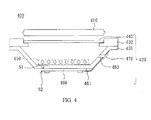
- FIG. 4 is a schematic view of a display apparatus in accordance with a second embodiment of the present invention.
- FIG. 5 is a schematic view of a display apparatus in accordance with a third embodiment of the present invention.
- a display apparatus 200 in accordance with a first embodiment of the present invention including a display panel 210 and a backlight module 220.
- the display panel 210 according to this embodiment is a liquid crystal display panel.
- the backlight module 220 is adapted for providing a backlight to the display panel 210, including a back bezel 231, a frame 232, an optical film 240, a light source 250, a control circuit board 260, a sensing unit 270 and a light guide element 280.
- the frame 232 is disposed at the top side of the back bezel 231 to hold the optical film 240 in place.
- the light source 250 according to this embodiment includes a plurality of red, green and blue LEDs (light emitting diodes) arranged in an array on the light output side of the back bezel 231.
- the control circuit board 260 is electrically connected with the light source 250 for controlling driving of the light source 250.
- the control circuit board 260 uses a single-sided PCB, having a first side S 1 and a second side S2 opposite to the first side S 1. As shown in FIG. 2 , the first side S 1 of the control circuit board 260 is closely attached to the side of the back bezel 231 that does not output light and fixedly secured thereto by means of a plug or screw joint.
- the sensing unit 270 and the other integrated devices of the control circuit board 260 are arranged on one same side of the control circuit board 260, namely, the second side S2. Further, holes 291 and 292 are respectively formed on the back bezel 231 and the control circuit board 260.
- the light guide element 280 is inserted through the holes 291 and 292 guides a part of the light produced by the light source 250 out of the back bezel 231 to the sensing unit 270. It must be pointed out that using the light guide element 280 is simply to guide the light to the sensing unit 270. However, the use of the light guide element 280 is not a limitation. Light may be directly guided by the holes 291 and 292 to the sensing unit 270.
- the sensing unit 270 may be a photosensor, photodiode or phototransistor. As shown in FIG. 3 , the sensing unit 270 according to this first embodiment includes a body 271, a connection portion 272 (the slated area) and a light sensing portion 273. The connection portion 272 and the light sensing portion 273 are located on one same side of the body 271. As shown in FIG. 2 , the connection portion 272 is electrically connected to the respective pins or lead wires at the second side S2 of the control circuit board 260, and the light sensing portion 273 faces the holes 291 and 292 to receive a part of the light that is transferred through the light guide element 280.
- the light emitted by the light source 250 is radiated onto the display panel 210 through the optical film 240, enabling the display apparatus 200 to display the desired picture image.
- the sensing unit 270 converts the light signal received through the light sensing portion 273 into a corresponding electrical signal, and transmits the electrical signal to the control circuit board 260 through the connection portion 272 so that the control circuit board 260 knows the current brightness performance of the light source 250.
- the control circuit board 260 utilizes the sensing unit 270 to detect the brightness performance of the light source 250, compares the detection result with pre-stored data for analysis, and controls the operation of the light source 250 subject to the analysis result, maintaining the brightness performance of the backlight module 220 at the expected level
- control circuit board 260 when compared with the prior art design, direct bonding between the control circuit board 260 and the back bezel 231 according to the present invention effectively reduce the dimension of the backlight module 220 without affecting brightness performance. Further, except the advantage that the control circuit board 260 may use a relatively cheaper single-sided PCB, this embodiment allows the sensing unit 270 and the other integrated devices to be arranged on the same side, facilitating fabrication and further calibration and maintenance.
- a display apparatus 400 in accordance with a second embodiment of the present invention is substantially similar to the aforesaid first embodiment with the exception that the backlight module 420 of the display apparatus 400 according to this second embodiment further includes a circuit board 461.
- the circuit board 461 for example, is a flexible circuit board, having one end affixed to one lateral side of the back bezel 431 by means of a plug or screw joint and the other end is arranged on the second side S2 of the control circuit board 460 to be electrically connected to the control circuit board 460.
- the sensing unit 470 is arranged on the end of the circuit board 461, as shown in FIG.
- a light guide structure formed of, for example, holes and light guide element 480, is provided to receive a part of the light that is radiated onto the lateral side of the back bezel 431, and the circuit board 460 transmits the converted electrical signal to the control circuit board 460 for processing.
- a display apparatus 500 in accordance with a third embodiment of the present invention is substantially similar to the aforesaid second embodiment with the exception that the circuit board 561 of the backlight module 520 of the display apparatus 500 according to this third embodiment has one end affixed to one lateral side of the frame 532 and the other end electrically connected to the control circuit board 560.
- the sensing unit 570 according to the position where the sensing unit 570 is arranged on the circuit board 561, the sensing unit 570 receives a part of the light that goes out of one lateral side of the optical film 540, and the circuit board 561 transmits the converted electrical signal to the control circuit board 560 for processing.
- the number and distribution locations of the sensing unit may be adjusted subject to requirements to enhance detection accuracy.
- the fixation arrangement of the control circuit board or circuit board may be changed subject to installation and fabrication needs.
- the sensing unit is not limited to the structure used in FIG. 3 , i.e., the light sensing portion and the connection portion may be disposed at different sides of the body, or the light sensing portion may be made in any of a variety of other geometric shapes and the light guide structure is relatively changed to match the light sensing portion. Any modifications and enhancements shall not depart from the spirit and scope of the invention in which the control circuit board is closely attached to the back bezel to reduce the dimension and manufacturing cost of the backlight module.
- the backlight module and display apparatus using the same as described above embodiments is to have the control circuit board closely attached to the back bezel of the backlight module so that the sensing unit and the integrated devices of the control circuit board are arranged on the same side.
- This design effectively reduces the dimension and manufacturing cost of the backlight module, improves the installation efficiency of the backlight module without affecting the brightness performance of the backlight module.
- the invention facilitates further calibration and maintenance.
- the term "the invention”, “the present invention” or the like does not necessarily limit the claim scope to a specific embodiment, and the reference to particularly preferred exemplary embodiments of the invention does not imply a limitation on the invention, and no such limitation is to be inferred.
- the invention is limited only by the spirit and scope of the appended claims.
- the abstract of the disclosure is provided to comply with the rules requiring an abstract, which will allow a searcher to quickly ascertain the subject matter of the technical disclosure of any patent issued from this disclosure. It is submitted with the understanding that it will not be used to interpret or limit the scope or meaning of the claims. Any advantages and benefits described may not apply to all embodiments of the invention.
Landscapes
- Physics & Mathematics (AREA)
- Nonlinear Science (AREA)
- Mathematical Physics (AREA)
- Chemical & Material Sciences (AREA)
- Crystallography & Structural Chemistry (AREA)
- General Physics & Mathematics (AREA)
- Optics & Photonics (AREA)
- Liquid Crystal (AREA)
- Planar Illumination Modules (AREA)
- Devices For Indicating Variable Information By Combining Individual Elements (AREA)
- Arrangement Of Elements, Cooling, Sealing, Or The Like Of Lighting Devices (AREA)
Applications Claiming Priority (1)
| Application Number | Priority Date | Filing Date | Title |
|---|---|---|---|
| TW096210917U TWM326640U (en) | 2007-07-04 | 2007-07-04 | Back light module and display apparatus using the same |
Publications (1)
| Publication Number | Publication Date |
|---|---|
| EP2012177A1 true EP2012177A1 (de) | 2009-01-07 |
Family
ID=39496155
Family Applications (1)
| Application Number | Title | Priority Date | Filing Date |
|---|---|---|---|
| EP08008124A Withdrawn EP2012177A1 (de) | 2007-07-04 | 2008-04-28 | Rückbeleuchtungsmodul und Anzeigevorrichtung damit |
Country Status (3)
| Country | Link |
|---|---|
| EP (1) | EP2012177A1 (de) |
| JP (1) | JP3143499U (de) |
| TW (1) | TWM326640U (de) |
Cited By (1)
| Publication number | Priority date | Publication date | Assignee | Title |
|---|---|---|---|---|
| US9864220B2 (en) | 2013-05-30 | 2018-01-09 | Eizo Corporation | Optical sensor attachment structure for image display device |
Families Citing this family (1)
| Publication number | Priority date | Publication date | Assignee | Title |
|---|---|---|---|---|
| TWI522869B (zh) | 2009-12-17 | 2016-02-21 | 中強光電股份有限公司 | 光學觸控顯示裝置 |
Citations (6)
| Publication number | Priority date | Publication date | Assignee | Title |
|---|---|---|---|---|
| US6069676A (en) * | 1996-08-02 | 2000-05-30 | Citizen Electronics Co., Ltd. | Sequential color display device |
| US20030043107A1 (en) * | 2001-09-05 | 2003-03-06 | Ruby Joseph H. | LED backlight luminance sensing for LCDs |
| US20040174332A1 (en) * | 2003-03-03 | 2004-09-09 | Dong-Hoon Kim | Lamp driving apparatus, backlight assembly and liquid crystal display device using the same |
| US20050111225A1 (en) * | 2003-10-20 | 2005-05-26 | Samsung Electronics Co., Ltd. | Backlight assembly and display apparatus having the same |
| US20060243948A1 (en) * | 2005-03-25 | 2006-11-02 | Masaru Ishiwa | Liquid crystal display |
| US20070121318A1 (en) * | 2005-11-29 | 2007-05-31 | Sharp Kabushiki Kaisha | Backlight and liquid crystal display device |
-
2007
- 2007-07-04 TW TW096210917U patent/TWM326640U/zh not_active IP Right Cessation
-
2008
- 2008-04-28 EP EP08008124A patent/EP2012177A1/de not_active Withdrawn
- 2008-05-14 JP JP2008003099U patent/JP3143499U/ja not_active Expired - Lifetime
Patent Citations (6)
| Publication number | Priority date | Publication date | Assignee | Title |
|---|---|---|---|---|
| US6069676A (en) * | 1996-08-02 | 2000-05-30 | Citizen Electronics Co., Ltd. | Sequential color display device |
| US20030043107A1 (en) * | 2001-09-05 | 2003-03-06 | Ruby Joseph H. | LED backlight luminance sensing for LCDs |
| US20040174332A1 (en) * | 2003-03-03 | 2004-09-09 | Dong-Hoon Kim | Lamp driving apparatus, backlight assembly and liquid crystal display device using the same |
| US20050111225A1 (en) * | 2003-10-20 | 2005-05-26 | Samsung Electronics Co., Ltd. | Backlight assembly and display apparatus having the same |
| US20060243948A1 (en) * | 2005-03-25 | 2006-11-02 | Masaru Ishiwa | Liquid crystal display |
| US20070121318A1 (en) * | 2005-11-29 | 2007-05-31 | Sharp Kabushiki Kaisha | Backlight and liquid crystal display device |
Cited By (1)
| Publication number | Priority date | Publication date | Assignee | Title |
|---|---|---|---|---|
| US9864220B2 (en) | 2013-05-30 | 2018-01-09 | Eizo Corporation | Optical sensor attachment structure for image display device |
Also Published As
| Publication number | Publication date |
|---|---|
| TWM326640U (en) | 2008-02-01 |
| JP3143499U (ja) | 2008-07-24 |
Similar Documents
| Publication | Publication Date | Title |
|---|---|---|
| KR100898521B1 (ko) | 액정 디스플레이용 led 백라이트 휘도 검출 시스템 | |
| US7423626B2 (en) | Light-emission control circuit | |
| CN101153979B (zh) | 用于小型显示装置的背光组件和盖 | |
| US7717605B2 (en) | Liquid crystal display device | |
| KR101364997B1 (ko) | 백라이트 어셈블리 및 이를 구비한 표시 장치 | |
| JP4839379B2 (ja) | バックライト装置、及びこれを用いた表示装置 | |
| TWI391750B (zh) | 使用於發光設備中之光源單元 | |
| JP5172128B2 (ja) | バックライト装置、表示装置、バックライト装置の駆動方法 | |
| CN101713510B (zh) | 背光单元及装有该背光单元的液晶显示器 | |
| EP2530370A1 (de) | Beleuchtungsvorrichtung und anzeigevorrichtung | |
| US8004488B2 (en) | Light device including a multi-sensor unit and control method thereof | |
| KR20130030115A (ko) | 액정 표시 장치 | |
| CN112130377B (zh) | 显示装置及其控制方法 | |
| KR101404651B1 (ko) | 액정표시장치 | |
| KR101321230B1 (ko) | 액정표시장치 | |
| CN201083906Y (zh) | 背光模块及应用其的显示装置 | |
| JP2008298834A (ja) | 液晶表示装置 | |
| KR200390856Y1 (ko) | 발광다이오드 백라이트 장치 | |
| JP3143499U (ja) | バックライトモジュール及びそれを用いる表示装置 | |
| CN206725895U (zh) | 显示装置 | |
| TWI335569B (en) | Backlight control system for small size display, lcd panel therefor and method of making backlight control system | |
| CN211906917U (zh) | 一种液晶显示器的背光控制系统 | |
| KR20090060052A (ko) | 액정표시장치 | |
| US20070075217A1 (en) | Backlight module | |
| KR200399727Y1 (ko) | 조명제어신호를 위한 착탈식 입력저장부를 구비한발광다이오드 백라이트 장치 |
Legal Events
| Date | Code | Title | Description |
|---|---|---|---|
| PUAI | Public reference made under article 153(3) epc to a published international application that has entered the european phase |
Free format text: ORIGINAL CODE: 0009012 |
|
| AK | Designated contracting states |
Kind code of ref document: A1 Designated state(s): AT BE BG CH CY CZ DE DK EE ES FI FR GB GR HR HU IE IS IT LI LT LU LV MC MT NL NO PL PT RO SE SI SK TR |
|
| AX | Request for extension of the european patent |
Extension state: AL BA MK RS |
|
| AKX | Designation fees paid | ||
| STAA | Information on the status of an ep patent application or granted ep patent |
Free format text: STATUS: THE APPLICATION IS DEEMED TO BE WITHDRAWN |
|
| 18D | Application deemed to be withdrawn |
Effective date: 20090708 |
|
| REG | Reference to a national code |
Ref country code: DE Ref legal event code: 8566 |