EP2012029B1 - Dispositif de blocage d'un axe en rotation et/ou en translation, comprenant des moyens d'actionnement à mémoire de forme - Google Patents
Dispositif de blocage d'un axe en rotation et/ou en translation, comprenant des moyens d'actionnement à mémoire de forme Download PDFInfo
- Publication number
- EP2012029B1 EP2012029B1 EP07425421A EP07425421A EP2012029B1 EP 2012029 B1 EP2012029 B1 EP 2012029B1 EP 07425421 A EP07425421 A EP 07425421A EP 07425421 A EP07425421 A EP 07425421A EP 2012029 B1 EP2012029 B1 EP 2012029B1
- Authority
- EP
- European Patent Office
- Prior art keywords
- pin
- spring
- shape memory
- rotation
- locking device
- Prior art date
- Legal status (The legal status is an assumption and is not a legal conclusion. Google has not performed a legal analysis and makes no representation as to the accuracy of the status listed.)
- Not-in-force
Links
Images


Classifications
-
- F—MECHANICAL ENGINEERING; LIGHTING; HEATING; WEAPONS; BLASTING
- F16—ENGINEERING ELEMENTS AND UNITS; GENERAL MEASURES FOR PRODUCING AND MAINTAINING EFFECTIVE FUNCTIONING OF MACHINES OR INSTALLATIONS; THERMAL INSULATION IN GENERAL
- F16C—SHAFTS; FLEXIBLE SHAFTS; ELEMENTS OR CRANKSHAFT MECHANISMS; ROTARY BODIES OTHER THAN GEARING ELEMENTS; BEARINGS
- F16C11/00—Pivots; Pivotal connections
- F16C11/04—Pivotal connections
- F16C11/10—Arrangements for locking
- F16C11/103—Arrangements for locking frictionally clamped
-
- F—MECHANICAL ENGINEERING; LIGHTING; HEATING; WEAPONS; BLASTING
- F16—ENGINEERING ELEMENTS AND UNITS; GENERAL MEASURES FOR PRODUCING AND MAINTAINING EFFECTIVE FUNCTIONING OF MACHINES OR INSTALLATIONS; THERMAL INSULATION IN GENERAL
- F16M—FRAMES, CASINGS OR BEDS OF ENGINES, MACHINES OR APPARATUS, NOT SPECIFIC TO ENGINES, MACHINES OR APPARATUS PROVIDED FOR ELSEWHERE; STANDS; SUPPORTS
- F16M11/00—Stands or trestles as supports for apparatus or articles placed thereon Stands for scientific apparatus such as gravitational force meters
- F16M11/02—Heads
- F16M11/04—Means for attachment of apparatus; Means allowing adjustment of the apparatus relatively to the stand
- F16M11/06—Means for attachment of apparatus; Means allowing adjustment of the apparatus relatively to the stand allowing pivoting
-
- F—MECHANICAL ENGINEERING; LIGHTING; HEATING; WEAPONS; BLASTING
- F16—ENGINEERING ELEMENTS AND UNITS; GENERAL MEASURES FOR PRODUCING AND MAINTAINING EFFECTIVE FUNCTIONING OF MACHINES OR INSTALLATIONS; THERMAL INSULATION IN GENERAL
- F16M—FRAMES, CASINGS OR BEDS OF ENGINES, MACHINES OR APPARATUS, NOT SPECIFIC TO ENGINES, MACHINES OR APPARATUS PROVIDED FOR ELSEWHERE; STANDS; SUPPORTS
- F16M2200/00—Details of stands or supports
- F16M2200/02—Locking means
- F16M2200/021—Locking means for rotational movement
- F16M2200/024—Locking means for rotational movement by positive interaction, e.g. male-female connections
-
- F—MECHANICAL ENGINEERING; LIGHTING; HEATING; WEAPONS; BLASTING
- F16—ENGINEERING ELEMENTS AND UNITS; GENERAL MEASURES FOR PRODUCING AND MAINTAINING EFFECTIVE FUNCTIONING OF MACHINES OR INSTALLATIONS; THERMAL INSULATION IN GENERAL
- F16M—FRAMES, CASINGS OR BEDS OF ENGINES, MACHINES OR APPARATUS, NOT SPECIFIC TO ENGINES, MACHINES OR APPARATUS PROVIDED FOR ELSEWHERE; STANDS; SUPPORTS
- F16M2200/00—Details of stands or supports
- F16M2200/04—Balancing means
- F16M2200/044—Balancing means for balancing rotational movement of the undercarriage
Definitions
- the present invention relates to locking devices for preventing the rotation and/or the axial movement of a pin, of the type including a coil spring wound around at least a portion of the pin.
- the aforesaid spring has one end rigidly connected to a support structure. In the undeformed condition, the spring has an internal diameter lower than the diameter of the pin, whereby in its rest condition, it is tightened around the pin such as to prevent a rotation thereof at least in one direction and/or an axial movement in any direction.
- means are further provided for causing unwinding of the turns of the spring, for the purpose of temporarily releasing the device, enabling a rotation and/or an axial movement of the pin.
- a device of the above indicated type is described, for example, in GB-A-2 078 846 .
- the invention relates to a locking device of the type indicated in the preamble of claim 1.
- a device of this type is known from WO-A-2005/005828 .
- a device including a coil spring wound around a pin to prevent rotation of the pin, where the coil springitself is made of a shape memory material which is expanded when activated, is known from US-A-20030106761 .
- the object of the present invention is to provide a device of this type which is simpler and more efficient with respect to the known devices.
- a further object of the present invention is to provide a device of the above specified type which has releasing means which are also suitable to be arranged for an electric actuation, without for this reason involving a complicated and/or cumbersome and/or expensive structure.
- a further object of the invention is to provide a device of the above specified type which is particularly suitable for being used on articulation pins of movable parts, such as in applications on-board of vehicles the articulation pin of a lid in the compartment, such as an articulated lid on the dashboard or a lid on an armrest, or still for a door of a refueling inlet of a fuel tank, or also, for example, on the articulation pin of a sun-shade on the vehicle or a lid on the sun-shade.
- the aforesaid shape memory means for causing the unwinding of the spring turns are electrically operable.
- the shape memory means consist of a shape memory wire arranged through an axial hole of the aforesaid pin and having one end connected to the pin and the opposite end connected with an axially slidable actuating element, for causing the unwinding of the spring turns, said shape memory wire having a transition temperature above which it undergoes a reduction in length, so as to cause the displacement of said axially slidable element to a position which causes the unwinding of the turns of the spring.
- the end of the aforesaid spring which is opposite to the end connected to the support structure is connected to a shank radially extending towards the outside, which engages a helical slit formed in a tubular cylindrical wall forming part of said slidable actuating element.
- the sliding movement of the actuating element causes a rotation of the aforesaid end shank of the spring in the direction which determines an unwinding of the spring turns.
- the shape memory means is provided in a different form, namely, of a wound wire-actuator, according to what has been proposed in the previous European Patent Application EP06425135 of the same Applicant (still secret at the filing date of this application), whose publication number is EP-A-1830064 .
- Shape memory materials have been studied and used since long. The same Applicant is the owner of various patents on different applications of these materials to various devices, above all in the automotive field. They typically consist of nickel and titanium metal alloys which present the property of changing from a martensitic phase to an austenitic phase above a transition temperature.
- such transition temperature is arranged to a value higher than the ambient.temperature value.
- the heating of the shape memory material beyond the transition temperature is obtained electrically, by supplying an electric current through the shape memory material, so as to heat it by Joule effect.
- the use is not excluded of shape memory elements in which the passage beyond the transition temperature takes place due to direct heat application, when the temperature at which the above device is operating increases.
- the device according to the invention in the embodiments which are illustrated herein by way of example, is typically intended for being used for locking and releasing hinged members in which the torques at stake are not particularly remarkable.
- the device according to the invention can be associated to an articulation pin of an articulated lid within a vehicle compartment, for example a lid of a compartment on a vehicle dashboard, or a lid on an armrest or a central consolle in the vehicle compartment.
- a further application is the lid of the refueling inlet to the fuel tank or also the articulation pin of a sun-shade.
- All the aforesaid components typically have an articulation pin which could be locked, for holding the articulated member in a closed condition against a cooperating support, and temporarily released, for enabling an oscillation of the hinged member from its closed position to its opened position (or to its deployed position in case of a sun-shade).
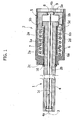
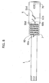
- numeral 1 generally designates a pin, having an end portion 1a which is contained within the cylindrical cavity 2a of a casing 2 in form of a cup-like cylindrical member.
- the pin 1 is rotatably supported by the wall of a cylindrical hole 2b formed in an end wall 2c of the casing 2.
- the casing 2 is intended for being mounted on a fixed structure, and the pin 1, which is thus rotatable around its axis 3 relative to the casing 2, can be rigidly connected to an oscillating element, such as for example an articulated lid or a sun-shade, on-board of a vehicle.
- the pin 1 consists of a tubular-shaped member, with a substantially uniform diameter and having an end collar 1b with an enlarged diameter.
- a wire 4 made of a shape memory alloy is arranged.
- One end 4a of the shape memory wire 4 is axially fixed to the end of the tubular pin 1 at the opposite side with respect to the collar 1b.
- a member 11, for example a ring made of a material having a low coefficient of friction is interposed between this end 4a of the shape memory wire and the tubular pin 1, for enabling the relative rotation between the pin 1 and the shape memory wire 4, thus preventing torsion stresses on the wire.
- the opposite end 4b of the shape memory wire 4 is rigidly connected to an actuating element 5 which, in the example shown, also has a cup-shaped body, with a bottom wall 5a to which the end 4b of the shape memory wire 4 is fixed, and a cylindrical skirt 5b which is slidably mounted within the cylindrical wall 2d of the casing 2 and above the collar 1b of the pin 1.
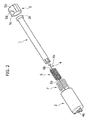
- the actuating element 5 further has axial ribs 5c on its external surface ( figure 2 ) which are received within axial cavities 2e formed on the internal surface of the cylindrical wall 2d of the casing 2.
- a coil spring 6 is wound, having one end 6a rigidly connected to the casing 2.
- the spring 6 is shaped such that, in its free and not deformed condition, it shows an internal diameter slightly lower than the outer diameter of the pin 1. Therefore, in the resting condition illustrated in figure 1 , the turns of the spring 6 are tightly wound around the pin 1 and therefore lock such pin by friction both against an axial movement and against a rotation in the direction causing winding of the spring turns.
- the end of the spring 6 opposite to the end 6a forms a radial shank 6b which engages a helical slit 5d formed in the cylindrical skirt 5b of the actuating element 5.
- a coil spring 7 is coaxially arranged, having one end abutting against the internal surface of the bottom wall 2c and the opposite end contacting the actuating element 5b so as to push it towards the resting position shown in figure 1 , defined by the contact between a disk 8 integral with the end 4b of the wire 4 and a shoulder 9 defined by the surface of a central hole formed in the bottom wall 5a of the slidable actuating element 5.
- the turns of the spring 6 are tightly wound around the portion 1a of the pin 1, so as to lock such pin, in particular with respect to a rotation movement apt to further wound the turns of the spring 6.
- Such condition can be exploited, for example, for maintaining in a closed locked condition an articulated lid on a vehicle, as the spring 6 prevents a rotation of the lid in the opening direction, while the surface of the cooperating support which receives the lid in the closed condition prevents a rotation of the lid in the opposite direction.
- a resilient ring 10 mounted above the pin 1 and abutting against the outer surface of the end wall 2c of the casing 2, prevents a relative movement of the pin 1 with respect to the casing 2 in the direction which would move the end 4a of the wire 4 towards the casing 2.
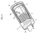
- the sliding of the element 5 determines a rotation of the shank 6b around the axis 3, due to the engagement of such shank within the helical slit 5d, in the direction apt to unwind the turns 6 of the spring.
- the turns of the spring 6 become loose and the locking action by friction of the pin is temporarily interrupted.
- the pin 1 can be rotated, for example for moving the lid connected thereto towards the opening condition or for moving a sun-shade connected thereto towards the deployed condition.
- Figures 3 , 4 show at an enlarged scale the resting position and the operating position of the element 5.
- the activation of the shape memory wire 4 can be obtained electrically, by supplying an electric current through the wire 4, by means of a connection (not shown) of the ends of the wire 4 to an electric supply through an electronic control unit which provides for activating and interrupting the electric supply as a function of a control signal imparted by the user.
- shape memory means for the release of the locking device formed in a completely different way from the one illustrated herein by way of example.
- a shape memory element formed as a wound wire or band is used, according to what has been proposed in the above mentioned European patent application of the same Applicant, which is able to directly impart a rotation to the spring si as to unwind the turns thereof, with an extremely reduced bulk.
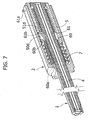
- the device according to the invention can be arranged for locking the pin against axial movements, in applications in which the pin is connected to movable elements which drive an axial movement of the pin.
- both the springs will have one end, 60a and 61a, respectively, rigidly connected to the support structure 2 and an opposite end in form of a radial shank, 60b and 61b, engaged within a helical slit 50d and 51d of the slidable actuating element 5, the slit being formed such that an axial movement of said slidable actuating element 5 causes a rotation of said shanks 60b and 61b around the axis 3 of the pin 1, tending to unwind the turns of both the coil springs 60 and 61.
- the shank 61a is engaged through a slot 70 of the element 5, to avoid an interference with the axial movement of the latter.
Claims (11)
- Dispositif de blocage pour empêcher la rotation et/ou le déplacement axial d'une tige (1), comprenant au moins un ressort hélicoïdal (6) enroulé autour d'une partie (1a) de ladite tige (1) et ayant une extrémité (6a) liée fixement à une structure de support (2), ce ressort (6) ayant, dans sa condition non déformée, un diamètre interne plus petit que le diamètre de ladite tige (1), de sorte que, lorsqu'il est en condition de repos, le ressort (6) est serré autour de ladite tige (1) afin d'empêcher sa rotation, au moins dans un sens, et/ou son déplacement axial dans l'un ou l'autre sens, des moyens étant prévus pour provoquer un déroulement des spires du ressort (6) afin de permettre une rotation et/ou un déplacement axial de la tige (1),
lesdits moyens pour provoquer le déroulement des spires du ressort (6) étant des moyens de manoeuvre à mémoire de forme (4),
caractérisé en ce que lesdits moyens à mémoire de forme se composent d'un fil à mémoire de forme (4) passé à travers une cavité axiale (1c) de la tige (1) et ayant une extrémité (4a) raccordée à la tige (1) et son autre extrémité (4b) raccordée à un élément de manoeuvre coulissant (5) pour provoquer un desserrement des spires dudit ressort hélicoïdal (6) suite à une réduction de longueur dudit fil à mémoire de forme (4) provoquée par le dépassement de la température de transition du matériau à mémoire de forme constituant le fil (4). - Dispositif de blocage selon la revendication 1, caractérisé en ce que lesdits moyens à mémoire de forme sont actionnables électriquement.
- Dispositif de blocage selon la revendication 1, caractérisé en ce que ledit ressort hélicoïdal (6) présente une extrémité (6) opposée à l'extrémité (6a) raccordée à la structure de support (2), qui définit un téton engagé dans une fente en hélice (5d) dudit élément de manoeuvre coulissant (5), de telle sorte qu'un déplacement axial dudit élément de manoeuvre coulissant (5) provoque une rotation dudit téton (6b) autour de l'axe (3) de la tige (1), ce qui tend à dérouler les spires du ressort hélicoïdal (6).
- Dispositif de blocage selon la revendication 3, caractérisé en ce que ladite structure de support est constituée d'un boîtier (2) ayant un corps cylindrique dans lequel ladite tige (1) est supportée en rotation, et en ce que ledit élément de manoeuvre (5) se compose d'un corps cylindrique monté de façon coulissante par accouplement prismatique dans le corps cylindrique de l'enveloppe (2).
- Dispositif de blocage selon la revendication 4, caractérisé en ce que des moyens élastiques (7) sont prévus, qui tendent à ramener l'élément de manoeuvre (5) vers une position de repos.
- Dispositif de blocage selon la revendication 1, caractérisé en ce que ledit ressort hélicoïdal (6), lorsqu'il est en condition de repos, empêche la rotation de ladite tige (1) dans le sens correspondant à un enroulement des spires du ressort (6).
- Dispositif de blocage selon la revendication 1, caractérisé en ce que, dans la condition de repos du ressort hélicoïdal (6), il empêche un déplacement axial de ladite tige (1).
- Dispositif de blocage selon la revendication 1, caractérisé en ce qu'il comprend un deuxième ressort hélicoïdal (61) qui est enroulé sur ladite tige (1) dans un sens opposé à celui du premier ressort hélicoïdal (60), de telle sorte que lesdits deux ressorts hélicoïdaux (60, 61) empêchent la rotation de ladite tige dans les deux sens, ledit élément de manoeuvre (5) étant adapté pour provoquer le desserrement des deux ressorts hélicoïdaux (60, 61) lors de l'activation du fil à mémoire de forme (4).
- Couvercle articulé à bord d'un véhicule, par exemple un couvercle de compartiment sur le tableau de bord d'un véhicule, ou un couvercle pour l'orifice de remplissage du réservoir d'essence du véhicule, caractérisé en ce qu'il est supporté par une tige associée à un dispositif de blocage selon l'une quelconque des revendications précédentes.
- Pare-soleil pour un véhicule, caractérisé en ce qu'il est accouplé à une tige d'articulation à laquelle est associé un dispositif de blocage selon l'une quelconque des revendications 1 à 9.
- Dispositif de blocage pour empêcher la rotation et/ou le déplacement axial d'une tige (1), comprenant au moins un ressort hélicoïdal (6) enroulé autour d'une partie (1a) de ladite tige (1) et ayant une extrémité (6a) liée fixement à une structure de support (2), ce ressort (6) ayant, dans sa condition non déformée, un diamètre interne plus petit que le diamètre de ladite tige (1), de sorte que, lorsqu'il est en condition de repos, le ressort (6) est serré autour de ladite tige (1) afin d'empêcher sa rotation, au moins dans un sens, et/ou son déplacement axial dans l'un ou l'autre sens, des moyens étant prévus pour provoquer un déroulement des spires du ressort (6) afin de permettre une rotation et/ou un déplacement axial de la tige (1),
lesdits moyens pour provoquer le déroulement des spires du ressort (6) étant des moyens de manoeuvre à mémoire de forme (4),
caractérisé en ce que lesdits moyens de manoeuvre à mémoire de forme se composent d'un actionneur ayant un élément enroulé à mémoire de forme.
Priority Applications (5)
| Application Number | Priority Date | Filing Date | Title |
|---|---|---|---|
| EP07425421A EP2012029B1 (fr) | 2007-07-06 | 2007-07-06 | Dispositif de blocage d'un axe en rotation et/ou en translation, comprenant des moyens d'actionnement à mémoire de forme |
| DE602007003212T DE602007003212D1 (de) | 2007-07-06 | 2007-07-06 | Dreh- und/oder Verschiebeverriegelungsvorrichtung eines Bolzens mit Formgedächtnisentriegelung |
| AT07425421T ATE448412T1 (de) | 2007-07-06 | 2007-07-06 | Dreh- und/oder verschiebeverriegelungsvorrichtung eines bolzens mit formgedächtnisentriegelung |
| US12/127,624 US8408365B2 (en) | 2007-07-06 | 2008-05-27 | Locking device for preventing a rotation and/or an axial movement of a pin, including shape memory releasing means |
| CN2008101100533A CN101338773B (zh) | 2007-07-06 | 2008-05-29 | 用于防止销的旋转和/或轴向移动的锁定装置 |
Applications Claiming Priority (1)
| Application Number | Priority Date | Filing Date | Title |
|---|---|---|---|
| EP07425421A EP2012029B1 (fr) | 2007-07-06 | 2007-07-06 | Dispositif de blocage d'un axe en rotation et/ou en translation, comprenant des moyens d'actionnement à mémoire de forme |
Publications (2)
| Publication Number | Publication Date |
|---|---|
| EP2012029A1 EP2012029A1 (fr) | 2009-01-07 |
| EP2012029B1 true EP2012029B1 (fr) | 2009-11-11 |
Family
ID=38662802
Family Applications (1)
| Application Number | Title | Priority Date | Filing Date |
|---|---|---|---|
| EP07425421A Not-in-force EP2012029B1 (fr) | 2007-07-06 | 2007-07-06 | Dispositif de blocage d'un axe en rotation et/ou en translation, comprenant des moyens d'actionnement à mémoire de forme |
Country Status (5)
| Country | Link |
|---|---|
| US (1) | US8408365B2 (fr) |
| EP (1) | EP2012029B1 (fr) |
| CN (1) | CN101338773B (fr) |
| AT (1) | ATE448412T1 (fr) |
| DE (1) | DE602007003212D1 (fr) |
Families Citing this family (11)
| Publication number | Priority date | Publication date | Assignee | Title |
|---|---|---|---|---|
| ATE360761T1 (de) * | 2004-12-30 | 2007-05-15 | Fiat Ricerche | Formgedächtnisbetätigungseinrichtung mit überspannungsschädensschutz |
| JP2009299487A (ja) * | 2008-06-10 | 2009-12-24 | Olympus Corp | 形状記憶合金アクチュエータ |
| EP2430322B1 (fr) * | 2009-05-15 | 2016-01-27 | ABB Technology Ltd | Dispositif de verrouillage pour limiter le mouvement rotatif |
| WO2010132997A1 (fr) * | 2009-05-19 | 2010-11-25 | Erick Girouard | Soupape avec déclencheur activé par la température |
| US20130175394A1 (en) * | 2012-01-10 | 2013-07-11 | Dale O. Cipra | Adjustable spring system and method of adjusting spring rate |
| US10577873B2 (en) | 2015-02-13 | 2020-03-03 | Halliburton Energy Services, Inc. | Shape memory alloy rope socket for a downhole tool |
| US11071377B2 (en) * | 2018-03-02 | 2021-07-27 | Ergotron, Inc. | Height adjustable platforms and associated mechanisms |
| CN112165886B (zh) | 2018-03-02 | 2022-08-23 | 爱格升公司 | 高度可调整平台和相关联机构 |
| US20200131824A1 (en) * | 2018-10-31 | 2020-04-30 | JKO Improvements LLC | Automatic Emergency Door Closure |
| CN209586923U (zh) * | 2019-02-14 | 2019-11-05 | 欧普照明股份有限公司 | 扭簧可变阻尼转轴 |
| US11619076B2 (en) * | 2020-10-29 | 2023-04-04 | Inteva Products, Llc | Cable return assist assembly for vehicle latch mechanism |
Family Cites Families (26)
| Publication number | Priority date | Publication date | Assignee | Title |
|---|---|---|---|---|
| US3874480A (en) * | 1972-04-03 | 1975-04-01 | Porter Co P L | Friction brake mechanism |
| US4257497A (en) * | 1977-03-14 | 1981-03-24 | Schroeder Karl S | Magnetically triggered and electronically controlled torsion brake |
| US4411339A (en) * | 1980-06-06 | 1983-10-25 | P. L. Porter Co. | Friction lock mechanisms |
| BR8100211A (pt) | 1980-06-06 | 1981-05-12 | Porter Co P L | Trava mecanica de atrito |
| US4526047A (en) * | 1982-12-07 | 1985-07-02 | Pacific Scientific Company | Energy absorber |
| US4577730A (en) * | 1983-08-30 | 1986-03-25 | P. L. Porter Company | Mechanical lock |
| KR960002058B1 (ko) * | 1988-03-04 | 1996-02-10 | 니혼핫죠 가부시기가이샤 | 축 잠금장치 |
| US4991675A (en) * | 1988-10-11 | 1991-02-12 | Navistar International Transportation Corp. | Hood tilt mechanism |
| US5150771A (en) * | 1990-05-11 | 1992-09-29 | P. L. Porter Company | Coil spring or friction-lock mechanisms |
| US5819881A (en) * | 1995-07-24 | 1998-10-13 | P. L. Porter Co. | Dual locking linear mechanical lock for high loads |
| US5771742A (en) * | 1995-09-11 | 1998-06-30 | Tini Alloy Company | Release device for retaining pin |
| US5794470A (en) * | 1996-06-25 | 1998-08-18 | P.L. Porter Co. | Mechanical seat lock |
| US6164419A (en) * | 1999-04-21 | 2000-12-26 | P. L. Porter Co. | Mechanical seat lock with translating rod that does not rotate |
| US6454775B1 (en) * | 1999-12-06 | 2002-09-24 | Bacchus Vascular Inc. | Systems and methods for clot disruption and retrieval |
| ITTO20010618A1 (it) * | 2001-06-27 | 2002-12-27 | Fiat Ricerche | Dispositivo attuatore a cavo flessibile incorporante un elemento a memoria di forma. |
| US20030106761A1 (en) | 2001-12-07 | 2003-06-12 | Taylor William Morris | Shape memory alloy wrap spring clutch |
| US6907961B2 (en) * | 2002-06-11 | 2005-06-21 | Cooper Cameron Corporation | Apparatus and method for retarding translation between two bodies |
| US20040099491A1 (en) * | 2002-11-25 | 2004-05-27 | Stevenson Paul D. | Electrically-applied transmission brake band |
| US6910557B2 (en) * | 2003-01-29 | 2005-06-28 | Illinois Tool Works Inc. | Slide damper with spring assist |
| US20050023086A1 (en) | 2003-06-30 | 2005-02-03 | Andrei Szilagyi | Shape memory alloy-actuated and bender-actuated helical spring brakes |
| ATE360761T1 (de) * | 2004-12-30 | 2007-05-15 | Fiat Ricerche | Formgedächtnisbetätigungseinrichtung mit überspannungsschädensschutz |
| US7216840B2 (en) * | 2005-03-23 | 2007-05-15 | Oasyschair Co., Ltd | Supporting framework for a swivel chair or swivel table |
| DE602006009617D1 (de) | 2006-03-01 | 2009-11-19 | Fiat Ricerche | Betätigungseinrichtung mit einem gewickelten SMA-Element |
| ATE407278T1 (de) * | 2006-03-16 | 2008-09-15 | Fiat Ricerche | Manuelle betätigungsvorrichtung mit formgedächtnishilfsantrieb |
| US8117938B2 (en) * | 2006-07-05 | 2012-02-21 | Ghsp, Inc. | Shifter with shape memory alloy and safety |
| US7931337B2 (en) * | 2008-03-20 | 2011-04-26 | Gm Global Technology Operations, Llc | Recliner release actuation through active materials |
-
2007
- 2007-07-06 DE DE602007003212T patent/DE602007003212D1/de active Active
- 2007-07-06 EP EP07425421A patent/EP2012029B1/fr not_active Not-in-force
- 2007-07-06 AT AT07425421T patent/ATE448412T1/de not_active IP Right Cessation
-
2008
- 2008-05-27 US US12/127,624 patent/US8408365B2/en not_active Expired - Fee Related
- 2008-05-29 CN CN2008101100533A patent/CN101338773B/zh not_active Expired - Fee Related
Also Published As
| Publication number | Publication date |
|---|---|
| US20090009026A1 (en) | 2009-01-08 |
| CN101338773A (zh) | 2009-01-07 |
| DE602007003212D1 (de) | 2009-12-24 |
| US8408365B2 (en) | 2013-04-02 |
| CN101338773B (zh) | 2010-12-22 |
| EP2012029A1 (fr) | 2009-01-07 |
| ATE448412T1 (de) | 2009-11-15 |
Similar Documents
| Publication | Publication Date | Title |
|---|---|---|
| EP2012029B1 (fr) | Dispositif de blocage d'un axe en rotation et/ou en translation, comprenant des moyens d'actionnement à mémoire de forme | |
| EP1399793B1 (fr) | Dispositif d'actionnement pourvu d'un cable flexible comprenant un element a memoire de forme | |
| EP3781767B1 (fr) | Ensemble de poignée de porte de véhicule | |
| US4457406A (en) | Improved friction lock | |
| US7942361B2 (en) | Webbing retracting device | |
| US7775596B2 (en) | Smartfold electronic actuation | |
| US7201430B2 (en) | Driving device for driving an open/close member | |
| US5568843A (en) | Precision linear mechanical lock | |
| GB2436703A (en) | An actuator and latch assembly for a folding seat for a vehicle | |
| US5967442A (en) | Force limiter for a seat belt restraint system | |
| EP1950079A1 (fr) | Dispositif d'inclinaison pour siège de véhicule | |
| JP4583368B2 (ja) | 自動車のステアリングシャフトをロックする装置 | |
| US20050115348A1 (en) | Actuator assembly | |
| EP2723958A1 (fr) | Dispositif de sécurité pour poignée de porte de véhicule | |
| WO2004005067A1 (fr) | Dispositif de verrouillage de poignee de deverrouillage actionne a distance | |
| US8109544B2 (en) | Unlocking device | |
| CA2031878A1 (fr) | Dispositif de rappel de ceintures de securite | |
| EP1738975B1 (fr) | Retracteur de ceinture de securite | |
| JP5990481B2 (ja) | ウェビング巻取装置 | |
| JP4166095B2 (ja) | シートベルトリトラクター | |
| KR100549911B1 (ko) | 댐퍼기구 | |
| EP0970857A1 (fr) | Enrouleur automatique de ceinture de securite | |
| US20130009352A1 (en) | Damper | |
| EP3251901A1 (fr) | Dispositif de verrouillage de direction | |
| JP2001106026A (ja) | プリテンショナ |
Legal Events
| Date | Code | Title | Description |
|---|---|---|---|
| PUAI | Public reference made under article 153(3) epc to a published international application that has entered the european phase |
Free format text: ORIGINAL CODE: 0009012 |
|
| 17P | Request for examination filed |
Effective date: 20080319 |
|
| AK | Designated contracting states |
Kind code of ref document: A1 Designated state(s): AT BE BG CH CY CZ DE DK EE ES FI FR GB GR HU IE IS IT LI LT LU LV MC MT NL PL PT RO SE SI SK TR |
|
| AX | Request for extension of the european patent |
Extension state: AL BA HR MK RS |
|
| GRAP | Despatch of communication of intention to grant a patent |
Free format text: ORIGINAL CODE: EPIDOSNIGR1 |
|
| GRAS | Grant fee paid |
Free format text: ORIGINAL CODE: EPIDOSNIGR3 |
|
| AKX | Designation fees paid |
Designated state(s): AT BE BG CH CY CZ DE DK EE ES FI FR GB GR HU IE IS IT LI LT LU LV MC MT NL PL PT RO SE SI SK TR |
|
| GRAA | (expected) grant |
Free format text: ORIGINAL CODE: 0009210 |
|
| AK | Designated contracting states |
Kind code of ref document: B1 Designated state(s): AT BE BG CH CY CZ DE DK EE ES FI FR GB GR HU IE IS IT LI LT LU LV MC MT NL PL PT RO SE SI SK TR |
|
| REG | Reference to a national code |
Ref country code: GB Ref legal event code: FG4D |
|
| REG | Reference to a national code |
Ref country code: CH Ref legal event code: EP |
|
| REG | Reference to a national code |
Ref country code: IE Ref legal event code: FG4D |
|
| REF | Corresponds to: |
Ref document number: 602007003212 Country of ref document: DE Date of ref document: 20091224 Kind code of ref document: P |
|
| NLV1 | Nl: lapsed or annulled due to failure to fulfill the requirements of art. 29p and 29m of the patents act | ||
| LTIE | Lt: invalidation of european patent or patent extension |
Effective date: 20091111 |
|
| PG25 | Lapsed in a contracting state [announced via postgrant information from national office to epo] |
Ref country code: SE Free format text: LAPSE BECAUSE OF FAILURE TO SUBMIT A TRANSLATION OF THE DESCRIPTION OR TO PAY THE FEE WITHIN THE PRESCRIBED TIME-LIMIT Effective date: 20091111 Ref country code: PT Free format text: LAPSE BECAUSE OF FAILURE TO SUBMIT A TRANSLATION OF THE DESCRIPTION OR TO PAY THE FEE WITHIN THE PRESCRIBED TIME-LIMIT Effective date: 20100311 Ref country code: LT Free format text: LAPSE BECAUSE OF FAILURE TO SUBMIT A TRANSLATION OF THE DESCRIPTION OR TO PAY THE FEE WITHIN THE PRESCRIBED TIME-LIMIT Effective date: 20091111 Ref country code: IS Free format text: LAPSE BECAUSE OF FAILURE TO SUBMIT A TRANSLATION OF THE DESCRIPTION OR TO PAY THE FEE WITHIN THE PRESCRIBED TIME-LIMIT Effective date: 20100311 Ref country code: ES Free format text: LAPSE BECAUSE OF FAILURE TO SUBMIT A TRANSLATION OF THE DESCRIPTION OR TO PAY THE FEE WITHIN THE PRESCRIBED TIME-LIMIT Effective date: 20100222 Ref country code: FI Free format text: LAPSE BECAUSE OF FAILURE TO SUBMIT A TRANSLATION OF THE DESCRIPTION OR TO PAY THE FEE WITHIN THE PRESCRIBED TIME-LIMIT Effective date: 20091111 |
|
| PG25 | Lapsed in a contracting state [announced via postgrant information from national office to epo] |
Ref country code: SI Free format text: LAPSE BECAUSE OF FAILURE TO SUBMIT A TRANSLATION OF THE DESCRIPTION OR TO PAY THE FEE WITHIN THE PRESCRIBED TIME-LIMIT Effective date: 20091111 Ref country code: CY Free format text: LAPSE BECAUSE OF FAILURE TO SUBMIT A TRANSLATION OF THE DESCRIPTION OR TO PAY THE FEE WITHIN THE PRESCRIBED TIME-LIMIT Effective date: 20091111 Ref country code: PL Free format text: LAPSE BECAUSE OF FAILURE TO SUBMIT A TRANSLATION OF THE DESCRIPTION OR TO PAY THE FEE WITHIN THE PRESCRIBED TIME-LIMIT Effective date: 20091111 Ref country code: LV Free format text: LAPSE BECAUSE OF FAILURE TO SUBMIT A TRANSLATION OF THE DESCRIPTION OR TO PAY THE FEE WITHIN THE PRESCRIBED TIME-LIMIT Effective date: 20091111 |
|
| PG25 | Lapsed in a contracting state [announced via postgrant information from national office to epo] |
Ref country code: AT Free format text: LAPSE BECAUSE OF FAILURE TO SUBMIT A TRANSLATION OF THE DESCRIPTION OR TO PAY THE FEE WITHIN THE PRESCRIBED TIME-LIMIT Effective date: 20091111 Ref country code: BE Free format text: LAPSE BECAUSE OF FAILURE TO SUBMIT A TRANSLATION OF THE DESCRIPTION OR TO PAY THE FEE WITHIN THE PRESCRIBED TIME-LIMIT Effective date: 20091111 |
|
| PG25 | Lapsed in a contracting state [announced via postgrant information from national office to epo] |
Ref country code: RO Free format text: LAPSE BECAUSE OF FAILURE TO SUBMIT A TRANSLATION OF THE DESCRIPTION OR TO PAY THE FEE WITHIN THE PRESCRIBED TIME-LIMIT Effective date: 20091111 Ref country code: EE Free format text: LAPSE BECAUSE OF FAILURE TO SUBMIT A TRANSLATION OF THE DESCRIPTION OR TO PAY THE FEE WITHIN THE PRESCRIBED TIME-LIMIT Effective date: 20091111 Ref country code: DK Free format text: LAPSE BECAUSE OF FAILURE TO SUBMIT A TRANSLATION OF THE DESCRIPTION OR TO PAY THE FEE WITHIN THE PRESCRIBED TIME-LIMIT Effective date: 20091111 Ref country code: BG Free format text: LAPSE BECAUSE OF FAILURE TO SUBMIT A TRANSLATION OF THE DESCRIPTION OR TO PAY THE FEE WITHIN THE PRESCRIBED TIME-LIMIT Effective date: 20100211 |
|
| PG25 | Lapsed in a contracting state [announced via postgrant information from national office to epo] |
Ref country code: CZ Free format text: LAPSE BECAUSE OF FAILURE TO SUBMIT A TRANSLATION OF THE DESCRIPTION OR TO PAY THE FEE WITHIN THE PRESCRIBED TIME-LIMIT Effective date: 20091111 Ref country code: SK Free format text: LAPSE BECAUSE OF FAILURE TO SUBMIT A TRANSLATION OF THE DESCRIPTION OR TO PAY THE FEE WITHIN THE PRESCRIBED TIME-LIMIT Effective date: 20091111 |
|
| PLBE | No opposition filed within time limit |
Free format text: ORIGINAL CODE: 0009261 |
|
| STAA | Information on the status of an ep patent application or granted ep patent |
Free format text: STATUS: NO OPPOSITION FILED WITHIN TIME LIMIT |
|
| 26N | No opposition filed |
Effective date: 20100812 |
|
| PG25 | Lapsed in a contracting state [announced via postgrant information from national office to epo] |
Ref country code: GR Free format text: LAPSE BECAUSE OF FAILURE TO SUBMIT A TRANSLATION OF THE DESCRIPTION OR TO PAY THE FEE WITHIN THE PRESCRIBED TIME-LIMIT Effective date: 20100212 |
|
| PG25 | Lapsed in a contracting state [announced via postgrant information from national office to epo] |
Ref country code: MC Free format text: LAPSE BECAUSE OF NON-PAYMENT OF DUE FEES Effective date: 20100731 |
|
| PG25 | Lapsed in a contracting state [announced via postgrant information from national office to epo] |
Ref country code: IE Free format text: LAPSE BECAUSE OF NON-PAYMENT OF DUE FEES Effective date: 20100706 |
|
| PG25 | Lapsed in a contracting state [announced via postgrant information from national office to epo] |
Ref country code: MT Free format text: LAPSE BECAUSE OF FAILURE TO SUBMIT A TRANSLATION OF THE DESCRIPTION OR TO PAY THE FEE WITHIN THE PRESCRIBED TIME-LIMIT Effective date: 20091111 |
|
| REG | Reference to a national code |
Ref country code: CH Ref legal event code: PL |
|
| GBPC | Gb: european patent ceased through non-payment of renewal fee |
Effective date: 20110706 |
|
| PG25 | Lapsed in a contracting state [announced via postgrant information from national office to epo] |
Ref country code: LI Free format text: LAPSE BECAUSE OF NON-PAYMENT OF DUE FEES Effective date: 20110731 Ref country code: CH Free format text: LAPSE BECAUSE OF NON-PAYMENT OF DUE FEES Effective date: 20110731 |
|
| PG25 | Lapsed in a contracting state [announced via postgrant information from national office to epo] |
Ref country code: GB Free format text: LAPSE BECAUSE OF NON-PAYMENT OF DUE FEES Effective date: 20110706 |
|
| PG25 | Lapsed in a contracting state [announced via postgrant information from national office to epo] |
Ref country code: LU Free format text: LAPSE BECAUSE OF NON-PAYMENT OF DUE FEES Effective date: 20100706 Ref country code: NL Free format text: LAPSE BECAUSE OF FAILURE TO SUBMIT A TRANSLATION OF THE DESCRIPTION OR TO PAY THE FEE WITHIN THE PRESCRIBED TIME-LIMIT Effective date: 20091111 Ref country code: HU Free format text: LAPSE BECAUSE OF FAILURE TO SUBMIT A TRANSLATION OF THE DESCRIPTION OR TO PAY THE FEE WITHIN THE PRESCRIBED TIME-LIMIT Effective date: 20100512 |
|
| PG25 | Lapsed in a contracting state [announced via postgrant information from national office to epo] |
Ref country code: TR Free format text: LAPSE BECAUSE OF FAILURE TO SUBMIT A TRANSLATION OF THE DESCRIPTION OR TO PAY THE FEE WITHIN THE PRESCRIBED TIME-LIMIT Effective date: 20091111 |
|
| REG | Reference to a national code |
Ref country code: FR Ref legal event code: PLFP Year of fee payment: 9 |
|
| PGFP | Annual fee paid to national office [announced via postgrant information from national office to epo] |
Ref country code: DE Payment date: 20150630 Year of fee payment: 9 |
|
| PGFP | Annual fee paid to national office [announced via postgrant information from national office to epo] |
Ref country code: FR Payment date: 20150629 Year of fee payment: 9 |
|
| PGFP | Annual fee paid to national office [announced via postgrant information from national office to epo] |
Ref country code: IT Payment date: 20150710 Year of fee payment: 9 |
|
| REG | Reference to a national code |
Ref country code: DE Ref legal event code: R119 Ref document number: 602007003212 Country of ref document: DE |
|
| PG25 | Lapsed in a contracting state [announced via postgrant information from national office to epo] |
Ref country code: DE Free format text: LAPSE BECAUSE OF NON-PAYMENT OF DUE FEES Effective date: 20170201 Ref country code: FR Free format text: LAPSE BECAUSE OF NON-PAYMENT OF DUE FEES Effective date: 20160801 |
|
| REG | Reference to a national code |
Ref country code: FR Ref legal event code: ST Effective date: 20170331 |
|
| PG25 | Lapsed in a contracting state [announced via postgrant information from national office to epo] |
Ref country code: IT Free format text: LAPSE BECAUSE OF NON-PAYMENT OF DUE FEES Effective date: 20160706 |