EP2012029B1 - Locking device for preventing a rotation and/or an axial movement of a pin, including shape memory releasing means - Google Patents
Locking device for preventing a rotation and/or an axial movement of a pin, including shape memory releasing means Download PDFInfo
- Publication number
- EP2012029B1 EP2012029B1 EP07425421A EP07425421A EP2012029B1 EP 2012029 B1 EP2012029 B1 EP 2012029B1 EP 07425421 A EP07425421 A EP 07425421A EP 07425421 A EP07425421 A EP 07425421A EP 2012029 B1 EP2012029 B1 EP 2012029B1
- Authority
- EP
- European Patent Office
- Prior art keywords
- pin
- spring
- shape memory
- rotation
- locking device
- Prior art date
- Legal status (The legal status is an assumption and is not a legal conclusion. Google has not performed a legal analysis and makes no representation as to the accuracy of the status listed.)
- Not-in-force
Links
Images


Classifications
-
- F—MECHANICAL ENGINEERING; LIGHTING; HEATING; WEAPONS; BLASTING
- F16—ENGINEERING ELEMENTS AND UNITS; GENERAL MEASURES FOR PRODUCING AND MAINTAINING EFFECTIVE FUNCTIONING OF MACHINES OR INSTALLATIONS; THERMAL INSULATION IN GENERAL
- F16C—SHAFTS; FLEXIBLE SHAFTS; ELEMENTS OR CRANKSHAFT MECHANISMS; ROTARY BODIES OTHER THAN GEARING ELEMENTS; BEARINGS
- F16C11/00—Pivots; Pivotal connections
- F16C11/04—Pivotal connections
- F16C11/10—Arrangements for locking
- F16C11/103—Arrangements for locking frictionally clamped
-
- F—MECHANICAL ENGINEERING; LIGHTING; HEATING; WEAPONS; BLASTING
- F16—ENGINEERING ELEMENTS AND UNITS; GENERAL MEASURES FOR PRODUCING AND MAINTAINING EFFECTIVE FUNCTIONING OF MACHINES OR INSTALLATIONS; THERMAL INSULATION IN GENERAL
- F16M—FRAMES, CASINGS OR BEDS OF ENGINES, MACHINES OR APPARATUS, NOT SPECIFIC TO ENGINES, MACHINES OR APPARATUS PROVIDED FOR ELSEWHERE; STANDS; SUPPORTS
- F16M11/00—Stands or trestles as supports for apparatus or articles placed thereon Stands for scientific apparatus such as gravitational force meters
- F16M11/02—Heads
- F16M11/04—Means for attachment of apparatus; Means allowing adjustment of the apparatus relatively to the stand
- F16M11/06—Means for attachment of apparatus; Means allowing adjustment of the apparatus relatively to the stand allowing pivoting
-
- F—MECHANICAL ENGINEERING; LIGHTING; HEATING; WEAPONS; BLASTING
- F16—ENGINEERING ELEMENTS AND UNITS; GENERAL MEASURES FOR PRODUCING AND MAINTAINING EFFECTIVE FUNCTIONING OF MACHINES OR INSTALLATIONS; THERMAL INSULATION IN GENERAL
- F16M—FRAMES, CASINGS OR BEDS OF ENGINES, MACHINES OR APPARATUS, NOT SPECIFIC TO ENGINES, MACHINES OR APPARATUS PROVIDED FOR ELSEWHERE; STANDS; SUPPORTS
- F16M2200/00—Details of stands or supports
- F16M2200/02—Locking means
- F16M2200/021—Locking means for rotational movement
- F16M2200/024—Locking means for rotational movement by positive interaction, e.g. male-female connections
-
- F—MECHANICAL ENGINEERING; LIGHTING; HEATING; WEAPONS; BLASTING
- F16—ENGINEERING ELEMENTS AND UNITS; GENERAL MEASURES FOR PRODUCING AND MAINTAINING EFFECTIVE FUNCTIONING OF MACHINES OR INSTALLATIONS; THERMAL INSULATION IN GENERAL
- F16M—FRAMES, CASINGS OR BEDS OF ENGINES, MACHINES OR APPARATUS, NOT SPECIFIC TO ENGINES, MACHINES OR APPARATUS PROVIDED FOR ELSEWHERE; STANDS; SUPPORTS
- F16M2200/00—Details of stands or supports
- F16M2200/04—Balancing means
- F16M2200/044—Balancing means for balancing rotational movement of the undercarriage
Abstract
Description
- The present invention relates to locking devices for preventing the rotation and/or the axial movement of a pin, of the type including a coil spring wound around at least a portion of the pin. In devices of this type, the aforesaid spring has one end rigidly connected to a support structure. In the undeformed condition, the spring has an internal diameter lower than the diameter of the pin, whereby in its rest condition, it is tightened around the pin such as to prevent a rotation thereof at least in one direction and/or an axial movement in any direction. In case of devices of this type, means are further provided for causing unwinding of the turns of the spring, for the purpose of temporarily releasing the device, enabling a rotation and/or an axial movement of the pin.
- A device of the above indicated type is described, for example, in
GB-A-2 078 846 - In particular the invention relates to a locking device of the type indicated in the preamble of
claim 1. A device of this type is known fromWO-A-2005/005828 . A device including a coil spring wound around a pin to prevent rotation of the pin, where the coil springitself is made of a shape memory material which is expanded when activated, is known fromUS-A-20030106761 . - The object of the present invention is to provide a device of this type which is simpler and more efficient with respect to the known devices.
- A further object of the present invention is to provide a device of the above specified type which has releasing means which are also suitable to be arranged for an electric actuation, without for this reason involving a complicated and/or cumbersome and/or expensive structure.
- A further object of the invention is to provide a device of the above specified type which is particularly suitable for being used on articulation pins of movable parts, such as in applications on-board of vehicles the articulation pin of a lid in the compartment, such as an articulated lid on the dashboard or a lid on an armrest, or still for a door of a refueling inlet of a fuel tank, or also, for example, on the articulation pin of a sun-shade on the vehicle or a lid on the sun-shade.
- These and other objects are attained, according to the invention, by the solutions as set forth in
claims 1 and 11.. - According to a first aspect of the invention, the aforesaid shape memory means for causing the unwinding of the spring turns are electrically operable.
- Also in the case of the aforesaid embodiment, the shape memory means consist of a shape memory wire arranged through an axial hole of the aforesaid pin and having one end connected to the pin and the opposite end connected with an axially slidable actuating element, for causing the unwinding of the spring turns, said shape memory wire having a transition temperature above which it undergoes a reduction in length, so as to cause the displacement of said axially slidable element to a position which causes the unwinding of the turns of the spring.
- Also in the case of such embodiment, the end of the aforesaid spring which is opposite to the end connected to the support structure is connected to a shank radially extending towards the outside, which engages a helical slit formed in a tubular cylindrical wall forming part of said slidable actuating element. In this way, the sliding movement of the actuating element causes a rotation of the aforesaid end shank of the spring in the direction which determines an unwinding of the spring turns. According to a second aspect of the invention, the shape memory means is provided in a different form, namely, of a wound wire-actuator, according to what has been proposed in the previous
European Patent Application EP06425135 EP-A-1830064 . - Shape memory materials have been studied and used since long. The same Applicant is the owner of various patents on different applications of these materials to various devices, above all in the automotive field. They typically consist of nickel and titanium metal alloys which present the property of changing from a martensitic phase to an austenitic phase above a transition temperature.
- In the case of the present invention, such transition temperature is arranged to a value higher than the ambient.temperature value. Also in the case of the preferred embodiment, the heating of the shape memory material beyond the transition temperature is obtained electrically, by supplying an electric current through the shape memory material, so as to heat it by Joule effect. However, the use is not excluded of shape memory elements in which the passage beyond the transition temperature takes place due to direct heat application, when the temperature at which the above device is operating increases.
- As already disclosed above, the device according to the invention, in the embodiments which are illustrated herein by way of example, is typically intended for being used for locking and releasing hinged members in which the torques at stake are not particularly remarkable. For example, the device according to the invention can be associated to an articulation pin of an articulated lid within a vehicle compartment, for example a lid of a compartment on a vehicle dashboard, or a lid on an armrest or a central consolle in the vehicle compartment. A further application is the lid of the refueling inlet to the fuel tank or also the articulation pin of a sun-shade. All the aforesaid components typically have an articulation pin which could be locked, for holding the articulated member in a closed condition against a cooperating support, and temporarily released, for enabling an oscillation of the hinged member from its closed position to its opened position (or to its deployed position in case of a sun-shade).
- Further features and advantages of the invention will appear from the following description with reference to the annexed drawings, given by mere way of not limiting example, in which:
-
figures 1 ,2 are a sectional view and an exploded perspective view of a preferred embodiment of the device according to the invention, -
figures 3 ,4 are perspective views at an enlarged scale of a particular of the device offigures 1 ,2 , in two different working conditions, and -
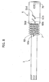
figures 5-8 show a variant, respectively in a perspective view, in an additional simplified perspective view, in a partly sectioned perspective view and in a side view which shows the device with the casing removed. - With reference to the drawings,
numeral 1 generally designates a pin, having an end portion 1a which is contained within thecylindrical cavity 2a of acasing 2 in form of a cup-like cylindrical member. Thepin 1 is rotatably supported by the wall of acylindrical hole 2b formed in anend wall 2c of thecasing 2. Thecasing 2 is intended for being mounted on a fixed structure, and thepin 1, which is thus rotatable around itsaxis 3 relative to thecasing 2, can be rigidly connected to an oscillating element, such as for example an articulated lid or a sun-shade, on-board of a vehicle. - The
pin 1 consists of a tubular-shaped member, with a substantially uniform diameter and having anend collar 1b with an enlarged diameter. Through theaxial cavity 1c of thepin 1, along theaxis 3, awire 4 made of a shape memory alloy is arranged. Oneend 4a of theshape memory wire 4 is axially fixed to the end of thetubular pin 1 at the opposite side with respect to thecollar 1b. A member 11, for example a ring made of a material having a low coefficient of friction is interposed between thisend 4a of the shape memory wire and thetubular pin 1, for enabling the relative rotation between thepin 1 and theshape memory wire 4, thus preventing torsion stresses on the wire. Theopposite end 4b of theshape memory wire 4 is rigidly connected to an actuatingelement 5 which, in the example shown, also has a cup-shaped body, with abottom wall 5a to which theend 4b of theshape memory wire 4 is fixed, and acylindrical skirt 5b which is slidably mounted within the cylindrical wall 2d of thecasing 2 and above thecollar 1b of thepin 1. The actuatingelement 5 further hasaxial ribs 5c on its external surface (figure 2 ) which are received withinaxial cavities 2e formed on the internal surface of the cylindrical wall 2d of thecasing 2. The prismatic engagement of theribs 5c within thecavities 2e prevents a rotation of the actuatingelement 5 around theaxis 3 relative to thecasing 2, leaving on the contrary the actuatingelement 5 free to axially slide in the direction of theaxis 3 with respect to thecasing 2 and with respect to thepin 1. - On the portion 1a of the
pin 1 which is arranged within thecavity 2a of thecasing 2 acoil spring 6 is wound, having oneend 6a rigidly connected to thecasing 2. Thespring 6 is shaped such that, in its free and not deformed condition, it shows an internal diameter slightly lower than the outer diameter of thepin 1. Therefore, in the resting condition illustrated infigure 1 , the turns of thespring 6 are tightly wound around thepin 1 and therefore lock such pin by friction both against an axial movement and against a rotation in the direction causing winding of the spring turns. - The end of the
spring 6 opposite to theend 6a forms aradial shank 6b which engages ahelical slit 5d formed in thecylindrical skirt 5b of the actuatingelement 5. - Finally, within the
cavity 2a of thecylindrical casing 2 acoil spring 7 is coaxially arranged, having one end abutting against the internal surface of thebottom wall 2c and the opposite end contacting the actuatingelement 5b so as to push it towards the resting position shown infigure 1 , defined by the contact between adisk 8 integral with theend 4b of thewire 4 and ashoulder 9 defined by the surface of a central hole formed in thebottom wall 5a of the slidable actuatingelement 5. - The operation of the device above described is the following.
- In the resting condition, as already shown above, the turns of the
spring 6 are tightly wound around the portion 1a of thepin 1, so as to lock such pin, in particular with respect to a rotation movement apt to further wound the turns of thespring 6. Such condition can be exploited, for example, for maintaining in a closed locked condition an articulated lid on a vehicle, as thespring 6 prevents a rotation of the lid in the opening direction, while the surface of the cooperating support which receives the lid in the closed condition prevents a rotation of the lid in the opposite direction. - Starting from the aforesaid resting condition, should the temperature of the
shape memory wire 4 exceed the transition value of such shape memory element, this latter is subjected to a reduction in length, whereby theend 4b fixed to theslidable element 5 moves closer to theend 4a, determining a leftward sliding movement (with reference tofigure 1 ) of theslidable element 5 with respect to thecasing 2 and with respect to thepin 1, against the action of thespring 7. - When the
shape memory wire 4 is operated, aresilient ring 10, mounted above thepin 1 and abutting against the outer surface of theend wall 2c of thecasing 2, prevents a relative movement of thepin 1 with respect to thecasing 2 in the direction which would move theend 4a of thewire 4 towards thecasing 2. - The sliding of the
element 5 determines a rotation of theshank 6b around theaxis 3, due to the engagement of such shank within thehelical slit 5d, in the direction apt to unwind theturns 6 of the spring. In such condition, therefore, the turns of thespring 6 become loose and the locking action by friction of the pin is temporarily interrupted. In such condition, therefore, thepin 1 can be rotated, for example for moving the lid connected thereto towards the opening condition or for moving a sun-shade connected thereto towards the deployed condition. - When the temperature of the
shape memory wire 4 returns below the transition temperature, thewire 4 returns to its longer configuration and the actuatingelement 5 returns to its starting position, under the force of thespring 7. In this way, the turns of thespring 6 are tightened again around thepin 1 by locking it against the rotation. -
Figures 3 ,4 show at an enlarged scale the resting position and the operating position of theelement 5. - The activation of the
shape memory wire 4 can be obtained electrically, by supplying an electric current through thewire 4, by means of a connection (not shown) of the ends of thewire 4 to an electric supply through an electronic control unit which provides for activating and interrupting the electric supply as a function of a control signal imparted by the user. - Naturally, without prejudice to the principle of the invention, the construction details and the embodiments could widely vary with respect to what has been described and shown by mere way of example.
- It is thus possible to provide shape memory means for the release of the locking device formed in a completely different way from the one illustrated herein by way of example. In a second aspect of the invention, a shape memory element formed as a wound wire or band is used, according to what has been proposed in the above mentioned European patent application of the same Applicant, which is able to directly impart a rotation to the spring si as to unwind the turns thereof, with an extremely reduced bulk. Likewise, the device according to the invention can be arranged for locking the pin against axial movements, in applications in which the pin is connected to movable elements which drive an axial movement of the pin.
- In order to obtain the locking of the
pin 1 in both directions of rotation, a couple ofcoil springs figures 5-8 ). In this case, both the springs will have one end, 60a and 61a, respectively, rigidly connected to thesupport structure 2 and an opposite end in form of a radial shank, 60b and 61b, engaged within ahelical slit element 5, the slit being formed such that an axial movement of said slidable actuatingelement 5 causes a rotation of saidshanks axis 3 of thepin 1, tending to unwind the turns of both thecoil springs structure 2, theshank 61a is engaged through aslot 70 of theelement 5, to avoid an interference with the axial movement of the latter. - Finally, various advantageous applications of the device according to the invention are possible, also different from those mentioned herein by mere way of example.
Claims (11)
- Locking device for preventing the rotation and/or the axial movement of a pin (1), including at least a coil spring (6) wound around a portion (la) of said pin (1) and having one end (6a) rigidly connected to a support structure (2), such spring (6) having, in its undeformed condition, an internal diameter lower than the diameter of said pin (1), whereby in a resting condition the spring (6) is tightened around said pin (1) to prevent a rotation thereof at least in one direction and/or an axial movement in any direction,
wherein means are provided for causing an unwinding of the turns of the spring (6) for enabling a rotation and/or an axial movement of the pin (1),
wherein said means for causing the unwinding of the turns of the spring (6) are shape memory actuating means (4),
characterized in that said shape memory means consist of a shape memory wire (4) arranged through an axial cavity (1c) of the pin (1) and having one end (4a) connected to the pin (1) and the opposite end (4b) connected to a slidable actuating element (5) for causing a loosening of the turns of said coil spring (6) following to a reduction in length of said shape memory wire (4) caused by the overcoming of the transition temperature of the shape memory material constituting the wire (4). - Locking device according to claim 1, characterized in that said shape memory means are electrically operable.
- Locking device according to claim 1, characterized in that said coil spring (6) presents one end (6) opposite to the end (6a) connected to the support structure (2) defining a shank engaged in a helical slit (5d) of said slidable actuating element (5), such that an axial movement of said slidable actuating element (5) causes a rotation of said shank (6b) around the axis (3) of the pin (1), tending to unwind the turns of the coil spring (6).
- Locking device according to claim 3, characterized in that said support structure consists of a casing (2) having a cylindrical body within which the aforesaid pin (1) is rotatably supported, and in that the aforesaid actuating element (5) consists of a cylindrical body slidably mounted with a prismatic coupling within the cylindrical body of the casing (2).
- Locking device according to claim 4, characterized in that resilient means (7) are provided, tending to bring back the actuating element (5) towards a resting position.
- Locking device according to claim 1, characterized in that said coil spring (6) prevents, in its resting condition, a rotation of said pin (1) in the direction corresponding to a winding of the turns of the spring (6).
- Locking device according to claim 1, characterized in that in the resting condition of the coil spring (6) it prevents an axial movement of said pin (1).
- Locking device according to claim 1, characterized in that it includes a second coil spring (61) which is wound on said pin (1) in a direction opposite to that of the first coil spring (60), so that said two coil springs (60,61) prevent rotation of said pin in the two opposite directions, said actuating element (5) being adapted to cause loosening of both coil springs (60,61) when the shape memory wire (4) is actuated.
- Articulated lid on-board of a vehicle, for example a compartment lid on a vehicle dashboard, or a lid of the refuel inlet to the tank of the vehicle, characterized in that it is supported by a pin associated with a locking device according to any one of the preceding claims.
- Sun-shadefor a vehicle, characterized in that it is connected to an articulation pin to which a locking device is associated according to any one of claims 1-9.
- Locking device for preventing the rotation and/or the axial movement of a pin (1), including at least a coil spring (6) wound around a portion (1a) of said pin (1) and having one end (6a) rigidly connected to a support structure (2), such spring (6) having, in its undeformed condition, an internal diameter lower than the diameter of said pin (1), whereby in a resting condition the spring (6) is tightened around said pin (1) to prevent a rotation thereof at least in one direction and/or an axial movement in any direction, wherein means are provided for causing an unwinding of the turns of the spring (6) for enabling a rotation and/or an axial movement of the pin (1),
wherein said means for causing the unwinding of the turns of the spring (6) are shape memory actuating means (4),
characterized in that the shape memory actuating means consist of an actuator with a wound shape memory element.
Priority Applications (5)
| Application Number | Priority Date | Filing Date | Title |
|---|---|---|---|
| EP07425421A EP2012029B1 (en) | 2007-07-06 | 2007-07-06 | Locking device for preventing a rotation and/or an axial movement of a pin, including shape memory releasing means |
| DE602007003212T DE602007003212D1 (en) | 2007-07-06 | 2007-07-06 | Rotary and / or sliding locking device of a shape memory unlocked bolt |
| AT07425421T ATE448412T1 (en) | 2007-07-06 | 2007-07-06 | ROTATION AND/OR SLIDE LOCKING DEVICE OF A BOLT WITH SHAPE MEMORY RELEASE |
| US12/127,624 US8408365B2 (en) | 2007-07-06 | 2008-05-27 | Locking device for preventing a rotation and/or an axial movement of a pin, including shape memory releasing means |
| CN2008101100533A CN101338773B (en) | 2007-07-06 | 2008-05-29 | Locking device for preventing a rotation and/or an axial movement of a pin |
Applications Claiming Priority (1)
| Application Number | Priority Date | Filing Date | Title |
|---|---|---|---|
| EP07425421A EP2012029B1 (en) | 2007-07-06 | 2007-07-06 | Locking device for preventing a rotation and/or an axial movement of a pin, including shape memory releasing means |
Publications (2)
| Publication Number | Publication Date |
|---|---|
| EP2012029A1 EP2012029A1 (en) | 2009-01-07 |
| EP2012029B1 true EP2012029B1 (en) | 2009-11-11 |
Family
ID=38662802
Family Applications (1)
| Application Number | Title | Priority Date | Filing Date |
|---|---|---|---|
| EP07425421A Not-in-force EP2012029B1 (en) | 2007-07-06 | 2007-07-06 | Locking device for preventing a rotation and/or an axial movement of a pin, including shape memory releasing means |
Country Status (5)
| Country | Link |
|---|---|
| US (1) | US8408365B2 (en) |
| EP (1) | EP2012029B1 (en) |
| CN (1) | CN101338773B (en) |
| AT (1) | ATE448412T1 (en) |
| DE (1) | DE602007003212D1 (en) |
Families Citing this family (11)
| Publication number | Priority date | Publication date | Assignee | Title |
|---|---|---|---|---|
| ATE360761T1 (en) * | 2004-12-30 | 2007-05-15 | Fiat Ricerche | SHAPE MEMORY ACTUATOR WITH SURGE VOLTAGE DAMAGE PROTECTION |
| JP2009299487A (en) * | 2008-06-10 | 2009-12-24 | Olympus Corp | Shape memory alloy actuator |
| WO2010130099A1 (en) * | 2009-05-15 | 2010-11-18 | Abb Technology Ltd. | Lock device for restricting rotational movement |
| CA2762667C (en) | 2009-05-19 | 2017-04-25 | Erick Girouard | Valve with temperature activated trigger |
| US20130175394A1 (en) * | 2012-01-10 | 2013-07-11 | Dale O. Cipra | Adjustable spring system and method of adjusting spring rate |
| US10577873B2 (en) | 2015-02-13 | 2020-03-03 | Halliburton Energy Services, Inc. | Shape memory alloy rope socket for a downhole tool |
| US10646033B2 (en) | 2018-03-02 | 2020-05-12 | Ergotron, Inc. | Height adjustable platforms and associated mechanisms |
| CN111836567B (en) * | 2018-03-02 | 2022-06-21 | 爱格升公司 | Height adjustable platform and associated mechanisms |
| US20200131824A1 (en) * | 2018-10-31 | 2020-04-30 | JKO Improvements LLC | Automatic Emergency Door Closure |
| CN209586923U (en) * | 2019-02-14 | 2019-11-05 | 欧普照明股份有限公司 | Torsional spring adaptive damping shaft |
| US11619076B2 (en) * | 2020-10-29 | 2023-04-04 | Inteva Products, Llc | Cable return assist assembly for vehicle latch mechanism |
Family Cites Families (26)
| Publication number | Priority date | Publication date | Assignee | Title |
|---|---|---|---|---|
| US3874480A (en) * | 1972-04-03 | 1975-04-01 | Porter Co P L | Friction brake mechanism |
| US4257497A (en) * | 1977-03-14 | 1981-03-24 | Schroeder Karl S | Magnetically triggered and electronically controlled torsion brake |
| US4411339A (en) * | 1980-06-06 | 1983-10-25 | P. L. Porter Co. | Friction lock mechanisms |
| BR8100211A (en) | 1980-06-06 | 1981-05-12 | Porter Co P L | MECHANICAL LOCK OF FRICTION |
| US4526047A (en) * | 1982-12-07 | 1985-07-02 | Pacific Scientific Company | Energy absorber |
| US4577730A (en) * | 1983-08-30 | 1986-03-25 | P. L. Porter Company | Mechanical lock |
| KR960002058B1 (en) * | 1988-03-04 | 1996-02-10 | 니혼핫죠 가부시기가이샤 | Shaft locking device |
| US4991675A (en) * | 1988-10-11 | 1991-02-12 | Navistar International Transportation Corp. | Hood tilt mechanism |
| US5150771A (en) * | 1990-05-11 | 1992-09-29 | P. L. Porter Company | Coil spring or friction-lock mechanisms |
| US5819881A (en) * | 1995-07-24 | 1998-10-13 | P. L. Porter Co. | Dual locking linear mechanical lock for high loads |
| US5771742A (en) * | 1995-09-11 | 1998-06-30 | Tini Alloy Company | Release device for retaining pin |
| US5794470A (en) * | 1996-06-25 | 1998-08-18 | P.L. Porter Co. | Mechanical seat lock |
| US6164419A (en) * | 1999-04-21 | 2000-12-26 | P. L. Porter Co. | Mechanical seat lock with translating rod that does not rotate |
| US6454775B1 (en) * | 1999-12-06 | 2002-09-24 | Bacchus Vascular Inc. | Systems and methods for clot disruption and retrieval |
| ITTO20010618A1 (en) * | 2001-06-27 | 2002-12-27 | Fiat Ricerche | FLEXIBLE CABLE ACTUATOR DEVICE INCORPORATING A SHAPE MEMORY ELEMENT. |
| US20030106761A1 (en) | 2001-12-07 | 2003-06-12 | Taylor William Morris | Shape memory alloy wrap spring clutch |
| US6907961B2 (en) * | 2002-06-11 | 2005-06-21 | Cooper Cameron Corporation | Apparatus and method for retarding translation between two bodies |
| US20040099491A1 (en) * | 2002-11-25 | 2004-05-27 | Stevenson Paul D. | Electrically-applied transmission brake band |
| US6910557B2 (en) * | 2003-01-29 | 2005-06-28 | Illinois Tool Works Inc. | Slide damper with spring assist |
| US20050023086A1 (en) | 2003-06-30 | 2005-02-03 | Andrei Szilagyi | Shape memory alloy-actuated and bender-actuated helical spring brakes |
| ATE360761T1 (en) * | 2004-12-30 | 2007-05-15 | Fiat Ricerche | SHAPE MEMORY ACTUATOR WITH SURGE VOLTAGE DAMAGE PROTECTION |
| US7216840B2 (en) * | 2005-03-23 | 2007-05-15 | Oasyschair Co., Ltd | Supporting framework for a swivel chair or swivel table |
| EP1830064B1 (en) | 2006-03-01 | 2009-10-07 | C.R.F. Società Consortile per Azioni | Actuator with a wound shape memory element |
| EP1835097B1 (en) * | 2006-03-16 | 2008-09-03 | CRF Societa'Consortile per Azioni | Manual actuating system assisted by a shape memory actuator |
| US8117938B2 (en) * | 2006-07-05 | 2012-02-21 | Ghsp, Inc. | Shifter with shape memory alloy and safety |
| US7931337B2 (en) * | 2008-03-20 | 2011-04-26 | Gm Global Technology Operations, Llc | Recliner release actuation through active materials |
-
2007
- 2007-07-06 AT AT07425421T patent/ATE448412T1/en not_active IP Right Cessation
- 2007-07-06 EP EP07425421A patent/EP2012029B1/en not_active Not-in-force
- 2007-07-06 DE DE602007003212T patent/DE602007003212D1/en active Active
-
2008
- 2008-05-27 US US12/127,624 patent/US8408365B2/en not_active Expired - Fee Related
- 2008-05-29 CN CN2008101100533A patent/CN101338773B/en not_active Expired - Fee Related
Also Published As
| Publication number | Publication date |
|---|---|
| US8408365B2 (en) | 2013-04-02 |
| DE602007003212D1 (en) | 2009-12-24 |
| CN101338773A (en) | 2009-01-07 |
| ATE448412T1 (en) | 2009-11-15 |
| US20090009026A1 (en) | 2009-01-08 |
| CN101338773B (en) | 2010-12-22 |
| EP2012029A1 (en) | 2009-01-07 |
Similar Documents
| Publication | Publication Date | Title |
|---|---|---|
| EP2012029B1 (en) | Locking device for preventing a rotation and/or an axial movement of a pin, including shape memory releasing means | |
| EP1399793B1 (en) | Actuator device with a flexible cable incorporating a shape-memory element | |
| EP3781767B1 (en) | Vehicle door handle assembly | |
| US4457406A (en) | Improved friction lock | |
| US7942361B2 (en) | Webbing retracting device | |
| US7201430B2 (en) | Driving device for driving an open/close member | |
| US20080129098A1 (en) | Smartfold electronic actuation | |
| US5568843A (en) | Precision linear mechanical lock | |
| GB2436703A (en) | An actuator and latch assembly for a folding seat for a vehicle | |
| EP1950079A1 (en) | Seat reclining apparatus for vehicle | |
| US5967442A (en) | Force limiter for a seat belt restraint system | |
| WO2012175599A1 (en) | Safety device for vehicle door handle | |
| WO2004005067A1 (en) | Remote-actuated release handle lockout | |
| US8109544B2 (en) | Unlocking device | |
| CA2031878A1 (en) | Seat belt retractor | |
| EP1738975B1 (en) | Seatbelt retractor | |
| JP4166095B2 (en) | Seat belt retractor | |
| KR100549911B1 (en) | Damper mechanism | |
| EP0970857A1 (en) | Seat belt retractor | |
| US9371054B2 (en) | Webbing take-up device | |
| US20130009352A1 (en) | Damper | |
| JP5474144B2 (en) | Seat belt retracting device | |
| EP3251901A1 (en) | Steering lock device | |
| JP2001106026A (en) | Pretensioner | |
| JP3740658B2 (en) | Shift lever device for starter motor |
Legal Events
| Date | Code | Title | Description |
|---|---|---|---|
| PUAI | Public reference made under article 153(3) epc to a published international application that has entered the european phase |
Free format text: ORIGINAL CODE: 0009012 |
|
| 17P | Request for examination filed |
Effective date: 20080319 |
|
| AK | Designated contracting states |
Kind code of ref document: A1 Designated state(s): AT BE BG CH CY CZ DE DK EE ES FI FR GB GR HU IE IS IT LI LT LU LV MC MT NL PL PT RO SE SI SK TR |
|
| AX | Request for extension of the european patent |
Extension state: AL BA HR MK RS |
|
| GRAP | Despatch of communication of intention to grant a patent |
Free format text: ORIGINAL CODE: EPIDOSNIGR1 |
|
| GRAS | Grant fee paid |
Free format text: ORIGINAL CODE: EPIDOSNIGR3 |
|
| AKX | Designation fees paid |
Designated state(s): AT BE BG CH CY CZ DE DK EE ES FI FR GB GR HU IE IS IT LI LT LU LV MC MT NL PL PT RO SE SI SK TR |
|
| GRAA | (expected) grant |
Free format text: ORIGINAL CODE: 0009210 |
|
| AK | Designated contracting states |
Kind code of ref document: B1 Designated state(s): AT BE BG CH CY CZ DE DK EE ES FI FR GB GR HU IE IS IT LI LT LU LV MC MT NL PL PT RO SE SI SK TR |
|
| REG | Reference to a national code |
Ref country code: GB Ref legal event code: FG4D |
|
| REG | Reference to a national code |
Ref country code: CH Ref legal event code: EP |
|
| REG | Reference to a national code |
Ref country code: IE Ref legal event code: FG4D |
|
| REF | Corresponds to: |
Ref document number: 602007003212 Country of ref document: DE Date of ref document: 20091224 Kind code of ref document: P |
|
| NLV1 | Nl: lapsed or annulled due to failure to fulfill the requirements of art. 29p and 29m of the patents act | ||
| LTIE | Lt: invalidation of european patent or patent extension |
Effective date: 20091111 |
|
| PG25 | Lapsed in a contracting state [announced via postgrant information from national office to epo] |
Ref country code: SE Free format text: LAPSE BECAUSE OF FAILURE TO SUBMIT A TRANSLATION OF THE DESCRIPTION OR TO PAY THE FEE WITHIN THE PRESCRIBED TIME-LIMIT Effective date: 20091111 Ref country code: PT Free format text: LAPSE BECAUSE OF FAILURE TO SUBMIT A TRANSLATION OF THE DESCRIPTION OR TO PAY THE FEE WITHIN THE PRESCRIBED TIME-LIMIT Effective date: 20100311 Ref country code: LT Free format text: LAPSE BECAUSE OF FAILURE TO SUBMIT A TRANSLATION OF THE DESCRIPTION OR TO PAY THE FEE WITHIN THE PRESCRIBED TIME-LIMIT Effective date: 20091111 Ref country code: IS Free format text: LAPSE BECAUSE OF FAILURE TO SUBMIT A TRANSLATION OF THE DESCRIPTION OR TO PAY THE FEE WITHIN THE PRESCRIBED TIME-LIMIT Effective date: 20100311 Ref country code: ES Free format text: LAPSE BECAUSE OF FAILURE TO SUBMIT A TRANSLATION OF THE DESCRIPTION OR TO PAY THE FEE WITHIN THE PRESCRIBED TIME-LIMIT Effective date: 20100222 Ref country code: FI Free format text: LAPSE BECAUSE OF FAILURE TO SUBMIT A TRANSLATION OF THE DESCRIPTION OR TO PAY THE FEE WITHIN THE PRESCRIBED TIME-LIMIT Effective date: 20091111 |
|
| PG25 | Lapsed in a contracting state [announced via postgrant information from national office to epo] |
Ref country code: SI Free format text: LAPSE BECAUSE OF FAILURE TO SUBMIT A TRANSLATION OF THE DESCRIPTION OR TO PAY THE FEE WITHIN THE PRESCRIBED TIME-LIMIT Effective date: 20091111 Ref country code: CY Free format text: LAPSE BECAUSE OF FAILURE TO SUBMIT A TRANSLATION OF THE DESCRIPTION OR TO PAY THE FEE WITHIN THE PRESCRIBED TIME-LIMIT Effective date: 20091111 Ref country code: PL Free format text: LAPSE BECAUSE OF FAILURE TO SUBMIT A TRANSLATION OF THE DESCRIPTION OR TO PAY THE FEE WITHIN THE PRESCRIBED TIME-LIMIT Effective date: 20091111 Ref country code: LV Free format text: LAPSE BECAUSE OF FAILURE TO SUBMIT A TRANSLATION OF THE DESCRIPTION OR TO PAY THE FEE WITHIN THE PRESCRIBED TIME-LIMIT Effective date: 20091111 |
|
| PG25 | Lapsed in a contracting state [announced via postgrant information from national office to epo] |
Ref country code: AT Free format text: LAPSE BECAUSE OF FAILURE TO SUBMIT A TRANSLATION OF THE DESCRIPTION OR TO PAY THE FEE WITHIN THE PRESCRIBED TIME-LIMIT Effective date: 20091111 Ref country code: BE Free format text: LAPSE BECAUSE OF FAILURE TO SUBMIT A TRANSLATION OF THE DESCRIPTION OR TO PAY THE FEE WITHIN THE PRESCRIBED TIME-LIMIT Effective date: 20091111 |
|
| PG25 | Lapsed in a contracting state [announced via postgrant information from national office to epo] |
Ref country code: RO Free format text: LAPSE BECAUSE OF FAILURE TO SUBMIT A TRANSLATION OF THE DESCRIPTION OR TO PAY THE FEE WITHIN THE PRESCRIBED TIME-LIMIT Effective date: 20091111 Ref country code: EE Free format text: LAPSE BECAUSE OF FAILURE TO SUBMIT A TRANSLATION OF THE DESCRIPTION OR TO PAY THE FEE WITHIN THE PRESCRIBED TIME-LIMIT Effective date: 20091111 Ref country code: DK Free format text: LAPSE BECAUSE OF FAILURE TO SUBMIT A TRANSLATION OF THE DESCRIPTION OR TO PAY THE FEE WITHIN THE PRESCRIBED TIME-LIMIT Effective date: 20091111 Ref country code: BG Free format text: LAPSE BECAUSE OF FAILURE TO SUBMIT A TRANSLATION OF THE DESCRIPTION OR TO PAY THE FEE WITHIN THE PRESCRIBED TIME-LIMIT Effective date: 20100211 |
|
| PG25 | Lapsed in a contracting state [announced via postgrant information from national office to epo] |
Ref country code: CZ Free format text: LAPSE BECAUSE OF FAILURE TO SUBMIT A TRANSLATION OF THE DESCRIPTION OR TO PAY THE FEE WITHIN THE PRESCRIBED TIME-LIMIT Effective date: 20091111 Ref country code: SK Free format text: LAPSE BECAUSE OF FAILURE TO SUBMIT A TRANSLATION OF THE DESCRIPTION OR TO PAY THE FEE WITHIN THE PRESCRIBED TIME-LIMIT Effective date: 20091111 |
|
| PLBE | No opposition filed within time limit |
Free format text: ORIGINAL CODE: 0009261 |
|
| STAA | Information on the status of an ep patent application or granted ep patent |
Free format text: STATUS: NO OPPOSITION FILED WITHIN TIME LIMIT |
|
| 26N | No opposition filed |
Effective date: 20100812 |
|
| PG25 | Lapsed in a contracting state [announced via postgrant information from national office to epo] |
Ref country code: GR Free format text: LAPSE BECAUSE OF FAILURE TO SUBMIT A TRANSLATION OF THE DESCRIPTION OR TO PAY THE FEE WITHIN THE PRESCRIBED TIME-LIMIT Effective date: 20100212 |
|
| PG25 | Lapsed in a contracting state [announced via postgrant information from national office to epo] |
Ref country code: MC Free format text: LAPSE BECAUSE OF NON-PAYMENT OF DUE FEES Effective date: 20100731 |
|
| PG25 | Lapsed in a contracting state [announced via postgrant information from national office to epo] |
Ref country code: IE Free format text: LAPSE BECAUSE OF NON-PAYMENT OF DUE FEES Effective date: 20100706 |
|
| PG25 | Lapsed in a contracting state [announced via postgrant information from national office to epo] |
Ref country code: MT Free format text: LAPSE BECAUSE OF FAILURE TO SUBMIT A TRANSLATION OF THE DESCRIPTION OR TO PAY THE FEE WITHIN THE PRESCRIBED TIME-LIMIT Effective date: 20091111 |
|
| REG | Reference to a national code |
Ref country code: CH Ref legal event code: PL |
|
| GBPC | Gb: european patent ceased through non-payment of renewal fee |
Effective date: 20110706 |
|
| PG25 | Lapsed in a contracting state [announced via postgrant information from national office to epo] |
Ref country code: LI Free format text: LAPSE BECAUSE OF NON-PAYMENT OF DUE FEES Effective date: 20110731 Ref country code: CH Free format text: LAPSE BECAUSE OF NON-PAYMENT OF DUE FEES Effective date: 20110731 |
|
| PG25 | Lapsed in a contracting state [announced via postgrant information from national office to epo] |
Ref country code: GB Free format text: LAPSE BECAUSE OF NON-PAYMENT OF DUE FEES Effective date: 20110706 |
|
| PG25 | Lapsed in a contracting state [announced via postgrant information from national office to epo] |
Ref country code: LU Free format text: LAPSE BECAUSE OF NON-PAYMENT OF DUE FEES Effective date: 20100706 Ref country code: NL Free format text: LAPSE BECAUSE OF FAILURE TO SUBMIT A TRANSLATION OF THE DESCRIPTION OR TO PAY THE FEE WITHIN THE PRESCRIBED TIME-LIMIT Effective date: 20091111 Ref country code: HU Free format text: LAPSE BECAUSE OF FAILURE TO SUBMIT A TRANSLATION OF THE DESCRIPTION OR TO PAY THE FEE WITHIN THE PRESCRIBED TIME-LIMIT Effective date: 20100512 |
|
| PG25 | Lapsed in a contracting state [announced via postgrant information from national office to epo] |
Ref country code: TR Free format text: LAPSE BECAUSE OF FAILURE TO SUBMIT A TRANSLATION OF THE DESCRIPTION OR TO PAY THE FEE WITHIN THE PRESCRIBED TIME-LIMIT Effective date: 20091111 |
|
| REG | Reference to a national code |
Ref country code: FR Ref legal event code: PLFP Year of fee payment: 9 |
|
| PGFP | Annual fee paid to national office [announced via postgrant information from national office to epo] |
Ref country code: DE Payment date: 20150630 Year of fee payment: 9 |
|
| PGFP | Annual fee paid to national office [announced via postgrant information from national office to epo] |
Ref country code: FR Payment date: 20150629 Year of fee payment: 9 |
|
| PGFP | Annual fee paid to national office [announced via postgrant information from national office to epo] |
Ref country code: IT Payment date: 20150710 Year of fee payment: 9 |
|
| REG | Reference to a national code |
Ref country code: DE Ref legal event code: R119 Ref document number: 602007003212 Country of ref document: DE |
|
| PG25 | Lapsed in a contracting state [announced via postgrant information from national office to epo] |
Ref country code: DE Free format text: LAPSE BECAUSE OF NON-PAYMENT OF DUE FEES Effective date: 20170201 Ref country code: FR Free format text: LAPSE BECAUSE OF NON-PAYMENT OF DUE FEES Effective date: 20160801 |
|
| REG | Reference to a national code |
Ref country code: FR Ref legal event code: ST Effective date: 20170331 |
|
| PG25 | Lapsed in a contracting state [announced via postgrant information from national office to epo] |
Ref country code: IT Free format text: LAPSE BECAUSE OF NON-PAYMENT OF DUE FEES Effective date: 20160706 |