EP3251901A1 - Steering lock device - Google Patents
Steering lock device Download PDFInfo
- Publication number
- EP3251901A1 EP3251901A1 EP17173211.8A EP17173211A EP3251901A1 EP 3251901 A1 EP3251901 A1 EP 3251901A1 EP 17173211 A EP17173211 A EP 17173211A EP 3251901 A1 EP3251901 A1 EP 3251901A1
- Authority
- EP
- European Patent Office
- Prior art keywords
- camshaft
- lock
- steering
- shaft portion
- projection
- Prior art date
- Legal status (The legal status is an assumption and is not a legal conclusion. Google has not performed a legal analysis and makes no representation as to the accuracy of the status listed.)
- Granted
Links
- 229920003002 synthetic resin Polymers 0.000 claims description 8
- 239000000057 synthetic resin Substances 0.000 claims description 8
- 238000010586 diagram Methods 0.000 description 4
- 238000005496 tempering Methods 0.000 description 2
- 229910000861 Mg alloy Inorganic materials 0.000 description 1
- 229910001297 Zn alloy Inorganic materials 0.000 description 1
- 230000004308 accommodation Effects 0.000 description 1
- 230000002411 adverse Effects 0.000 description 1
- 238000005266 casting Methods 0.000 description 1
- 230000003247 decreasing effect Effects 0.000 description 1
- 238000003754 machining Methods 0.000 description 1
- 238000004519 manufacturing process Methods 0.000 description 1
- 239000000463 material Substances 0.000 description 1
- 238000000926 separation method Methods 0.000 description 1
- 238000004088 simulation Methods 0.000 description 1
- 238000003466 welding Methods 0.000 description 1
Images


Classifications
-
- B—PERFORMING OPERATIONS; TRANSPORTING
- B60—VEHICLES IN GENERAL
- B60R—VEHICLES, VEHICLE FITTINGS, OR VEHICLE PARTS, NOT OTHERWISE PROVIDED FOR
- B60R25/00—Fittings or systems for preventing or indicating unauthorised use or theft of vehicles
- B60R25/01—Fittings or systems for preventing or indicating unauthorised use or theft of vehicles operating on vehicle systems or fittings, e.g. on doors, seats or windscreens
- B60R25/02—Fittings or systems for preventing or indicating unauthorised use or theft of vehicles operating on vehicle systems or fittings, e.g. on doors, seats or windscreens operating on the steering mechanism
- B60R25/021—Fittings or systems for preventing or indicating unauthorised use or theft of vehicles operating on vehicle systems or fittings, e.g. on doors, seats or windscreens operating on the steering mechanism restraining movement of the steering column or steering wheel hub, e.g. restraining means controlled by ignition switch
- B60R25/0211—Fittings or systems for preventing or indicating unauthorised use or theft of vehicles operating on vehicle systems or fittings, e.g. on doors, seats or windscreens operating on the steering mechanism restraining movement of the steering column or steering wheel hub, e.g. restraining means controlled by ignition switch comprising a locking member radially and linearly moved towards the steering column
- B60R25/02115—Fittings or systems for preventing or indicating unauthorised use or theft of vehicles operating on vehicle systems or fittings, e.g. on doors, seats or windscreens operating on the steering mechanism restraining movement of the steering column or steering wheel hub, e.g. restraining means controlled by ignition switch comprising a locking member radially and linearly moved towards the steering column key actuated
- B60R25/02126—Fittings or systems for preventing or indicating unauthorised use or theft of vehicles operating on vehicle systems or fittings, e.g. on doors, seats or windscreens operating on the steering mechanism restraining movement of the steering column or steering wheel hub, e.g. restraining means controlled by ignition switch comprising a locking member radially and linearly moved towards the steering column key actuated with linear bolt motion perpendicular to the lock axis
- B60R25/02128—Fittings or systems for preventing or indicating unauthorised use or theft of vehicles operating on vehicle systems or fittings, e.g. on doors, seats or windscreens operating on the steering mechanism restraining movement of the steering column or steering wheel hub, e.g. restraining means controlled by ignition switch comprising a locking member radially and linearly moved towards the steering column key actuated with linear bolt motion perpendicular to the lock axis comprising safety devices avoiding locking until removal of the key
- B60R25/02131—Fittings or systems for preventing or indicating unauthorised use or theft of vehicles operating on vehicle systems or fittings, e.g. on doors, seats or windscreens operating on the steering mechanism restraining movement of the steering column or steering wheel hub, e.g. restraining means controlled by ignition switch comprising a locking member radially and linearly moved towards the steering column key actuated with linear bolt motion perpendicular to the lock axis comprising safety devices avoiding locking until removal of the key by using an axially slidable lock cylinder
-
- B—PERFORMING OPERATIONS; TRANSPORTING
- B60—VEHICLES IN GENERAL
- B60R—VEHICLES, VEHICLE FITTINGS, OR VEHICLE PARTS, NOT OTHERWISE PROVIDED FOR
- B60R25/00—Fittings or systems for preventing or indicating unauthorised use or theft of vehicles
- B60R25/01—Fittings or systems for preventing or indicating unauthorised use or theft of vehicles operating on vehicle systems or fittings, e.g. on doors, seats or windscreens
- B60R25/02—Fittings or systems for preventing or indicating unauthorised use or theft of vehicles operating on vehicle systems or fittings, e.g. on doors, seats or windscreens operating on the steering mechanism
- B60R25/021—Fittings or systems for preventing or indicating unauthorised use or theft of vehicles operating on vehicle systems or fittings, e.g. on doors, seats or windscreens operating on the steering mechanism restraining movement of the steering column or steering wheel hub, e.g. restraining means controlled by ignition switch
- B60R25/0211—Fittings or systems for preventing or indicating unauthorised use or theft of vehicles operating on vehicle systems or fittings, e.g. on doors, seats or windscreens operating on the steering mechanism restraining movement of the steering column or steering wheel hub, e.g. restraining means controlled by ignition switch comprising a locking member radially and linearly moved towards the steering column
- B60R25/02115—Fittings or systems for preventing or indicating unauthorised use or theft of vehicles operating on vehicle systems or fittings, e.g. on doors, seats or windscreens operating on the steering mechanism restraining movement of the steering column or steering wheel hub, e.g. restraining means controlled by ignition switch comprising a locking member radially and linearly moved towards the steering column key actuated
- B60R25/02126—Fittings or systems for preventing or indicating unauthorised use or theft of vehicles operating on vehicle systems or fittings, e.g. on doors, seats or windscreens operating on the steering mechanism restraining movement of the steering column or steering wheel hub, e.g. restraining means controlled by ignition switch comprising a locking member radially and linearly moved towards the steering column key actuated with linear bolt motion perpendicular to the lock axis
- B60R25/02128—Fittings or systems for preventing or indicating unauthorised use or theft of vehicles operating on vehicle systems or fittings, e.g. on doors, seats or windscreens operating on the steering mechanism restraining movement of the steering column or steering wheel hub, e.g. restraining means controlled by ignition switch comprising a locking member radially and linearly moved towards the steering column key actuated with linear bolt motion perpendicular to the lock axis comprising safety devices avoiding locking until removal of the key
-
- B—PERFORMING OPERATIONS; TRANSPORTING
- B60—VEHICLES IN GENERAL
- B60R—VEHICLES, VEHICLE FITTINGS, OR VEHICLE PARTS, NOT OTHERWISE PROVIDED FOR
- B60R25/00—Fittings or systems for preventing or indicating unauthorised use or theft of vehicles
- B60R25/01—Fittings or systems for preventing or indicating unauthorised use or theft of vehicles operating on vehicle systems or fittings, e.g. on doors, seats or windscreens
- B60R25/02—Fittings or systems for preventing or indicating unauthorised use or theft of vehicles operating on vehicle systems or fittings, e.g. on doors, seats or windscreens operating on the steering mechanism
- B60R25/023—Countermeasures against the physical destruction of the steering lock
-
- B—PERFORMING OPERATIONS; TRANSPORTING
- B60—VEHICLES IN GENERAL
- B60R—VEHICLES, VEHICLE FITTINGS, OR VEHICLE PARTS, NOT OTHERWISE PROVIDED FOR
- B60R25/00—Fittings or systems for preventing or indicating unauthorised use or theft of vehicles
- B60R25/20—Means to switch the anti-theft system on or off
- B60R25/2063—Ignition switch geometry
-
- B—PERFORMING OPERATIONS; TRANSPORTING
- B60—VEHICLES IN GENERAL
- B60R—VEHICLES, VEHICLE FITTINGS, OR VEHICLE PARTS, NOT OTHERWISE PROVIDED FOR
- B60R25/00—Fittings or systems for preventing or indicating unauthorised use or theft of vehicles
- B60R25/01—Fittings or systems for preventing or indicating unauthorised use or theft of vehicles operating on vehicle systems or fittings, e.g. on doors, seats or windscreens
- B60R25/02—Fittings or systems for preventing or indicating unauthorised use or theft of vehicles operating on vehicle systems or fittings, e.g. on doors, seats or windscreens operating on the steering mechanism
- B60R25/021—Fittings or systems for preventing or indicating unauthorised use or theft of vehicles operating on vehicle systems or fittings, e.g. on doors, seats or windscreens operating on the steering mechanism restraining movement of the steering column or steering wheel hub, e.g. restraining means controlled by ignition switch
-
- Y—GENERAL TAGGING OF NEW TECHNOLOGICAL DEVELOPMENTS; GENERAL TAGGING OF CROSS-SECTIONAL TECHNOLOGIES SPANNING OVER SEVERAL SECTIONS OF THE IPC; TECHNICAL SUBJECTS COVERED BY FORMER USPC CROSS-REFERENCE ART COLLECTIONS [XRACs] AND DIGESTS
- Y10—TECHNICAL SUBJECTS COVERED BY FORMER USPC
- Y10T—TECHNICAL SUBJECTS COVERED BY FORMER US CLASSIFICATION
- Y10T70/00—Locks
- Y10T70/50—Special application
- Y10T70/5611—For control and machine elements
- Y10T70/5646—Rotary shaft
- Y10T70/565—Locked stationary
- Y10T70/5655—Housing-carried lock
- Y10T70/5664—Latching bolt
-
- Y—GENERAL TAGGING OF NEW TECHNOLOGICAL DEVELOPMENTS; GENERAL TAGGING OF CROSS-SECTIONAL TECHNOLOGIES SPANNING OVER SEVERAL SECTIONS OF THE IPC; TECHNICAL SUBJECTS COVERED BY FORMER USPC CROSS-REFERENCE ART COLLECTIONS [XRACs] AND DIGESTS
- Y10—TECHNICAL SUBJECTS COVERED BY FORMER USPC
- Y10T—TECHNICAL SUBJECTS COVERED BY FORMER US CLASSIFICATION
- Y10T70/00—Locks
- Y10T70/50—Special application
- Y10T70/5889—For automotive vehicles
- Y10T70/5956—Steering mechanism with switch
Definitions
- the present invention relates to a steering lock device that disables a steering operation.
- Japanese Laid-Open Patent Publication No. 2015-112987 describes a prior art steering lock device.
- the steering lock device includes a key cylinder, a camshaft, a lock stopper, and a lock bar.
- the camshaft is rotated about the axis of the camshaft.
- the rotation of the camshaft is transmitted by the lock stopper to the lock bar and moves the lock bar in a locking direction or an unlocking direction.
- the lock bar engages a steering wheel or a steering shaft to disable a steering operation.
- a state in which the steering operation is disabled may be referred to as the locked state.
- a state in which the steering operation is enabled may be referred to as the unlocked state.
- the inventors of the present application have developed a structure that maintains a steering lock device in the locked state when one tampers with the steering lock device from outside the steering lock device.
- a steering lock device includes a camshaft, a housing, and a lock bar.
- the camshaft includes a shaft portion having an axis, a lock actuation cam that radially projects from a first position of the shaft portion in an axial direction, and a projection that radially projects from a second position of the shaft portion that differs from the first position in the axial direction.
- the camshaft is rotated about the axis when a key cylinder is operated by a mechanical key.
- the housing rotatably accommodates the camshaft.
- the lock bar is moved by the lock actuation cam in a locking direction or an unlocking direction when the camshaft is rotated.
- the lock bar When the lock bar is moved in the locking direction, the lock bar engages a steering shaft to lock the steering shaft. When the lock bar is moved in the unlocking direction, the lock bar is disengaged from the steering shaft to unlock the steering shaft.
- the camshaft is configured so that the projection is separated from the shaft portion if a load exceeding a predetermined strength acts on the projection of the camshaft. The predetermined strength rotates the lock actuation cam to disengage the lock bar from the steering shaft.
- a third party who is attempting unauthorized unlocking may attempt to rotate the lock actuation cam by applying a load to the projection to rotate the camshaft.
- the projection when a load exceeding the predetermined strength acts on the projection, the projection is separated before rotation of the lock actuation cam disengages the lock bar from the steering shaft. Thus, the load cannot be applied to the projection to rotate the camshaft. This obviates unauthorized unlocking.
- the load exceeding the predetermined strength may be referred to as the large load.
- the shaft portion and the projection of the camshaft are formed integrally with each other.
- the camshaft includes a low-strength portion located where the projection and the shaft portion are connected to each other.
- the projection when the large load acts on the projection, breakage occurs from the low-strength portion and the projection is separated from the shaft portion (camshaft).
- the projection is configured to be separated from the shaft portion without increasing the number of components.
- the steering lock device is used with a vehicle shift lever that is shifted to a parking position and a non-parking position.
- the key cylinder is coupled to the housing.
- the housing includes an interlock attachment portion configured to attach a key interlock unit that prohibits removal of the mechanical key from the key cylinder unless the shift lever is shifted to the parking position.
- the projection includes a cam-shaped interlock cam that actuates the key interlock unit.
- the housing includes the interlock attachment portion and the key interlock unit is coupled to the housing
- the interlock cam is configured to be separated from the shaft portion when the large load acts on the interlock cam. This obviates the tampering attempted on the key interlock unit from unauthorized unlocking.
- the resistance to tempering is improved.
- the key interlock unit includes a synthetic resin case.
- the interlock cam is configured to be separated from the camshaft when a large load acts on the interlock cam. This improves the resistance to tampering.
- Fig. 1 illustrates an example of a steering lock device 1 that is configured to lock a steering wheel (not shown) to disable a steering operation of a vehicle.
- the steering lock device 1 includes a housing 2, which may be referred to as the lock body, and a cover 3.
- the housing 2 is formed from, for example, a magnesium alloy.
- the housing 2 includes a tubular portion, which has a longitudinal axis and two open ends, and a box-shaped portion 11, which has an opening in a side surface of the tubular portion.
- the housing 2 includes a support portion 12, which is opposite to the box-shaped portion 11.
- the support portion 12 may include a column support surface that is concaved in conformance with a convex outer surface of a steering column 5, which rotatably accommodates a steering shaft 4.
- the cover 3 is formed from, for example, a zinc alloy and is shaped to close the opening of the box-shaped portion 11.
- the cover 3 is fixed to the housing 2 by a plurality of press-fit pins 6.
- the steering lock device 1 is fitted to the steering column 5 by the support portion 12 of the housing 2 and fixed to the steering column 5 by a bracket (not shown).
- the housing 2 includes an opening 13 that is located in one end in the longitudinal direction (X-axis direction).
- the housing 2 includes an interlock attachment portion 14, which opens in a side surface of the box-shaped portion 11 and serves as a portion to which a key interlock unit 9 is attached.
- the key interlock unit 9 performs a key interlock that disables removal of the mechanical key 80 from the key cylinder 7 unless a shift lever 81 is shifted to a parking position.
- the steering lock device 1 includes a lock mechanism 21 that locks and unlocks the steering operation by engaging with the steering shaft 4 and disengaging from the steering shaft 4.
- the lock mechanism 21 includes a lock bar 22, which engages the steering shaft 4 to lock the steering shaft 4, a lock stopper 23, which is coupled to the lock bar 22, and a camshaft 24, which is rotated when the mechanical key 80 operated in the key cylinder 7.
- the housing 2 includes a component receptacle 26 that accommodates the lock bar 22, the lock stopper 23, and the camshaft 24.
- a plurality (three in illustrated example) of support walls 27 is arranged in the component receptacle 26 next to one another in the longitudinal direction of the housing 2 to separate the empty space of the component receptacle 26.
- Each of the support walls 27 includes an arcuate groove 28, in which the camshaft 24 is rotatably located. Additionally, a portion of the component receptacle 26 defines an accommodation space 29 that accommodates at least a portion of the key interlock unit 9 in the interlock attachment portion 14.
- the lock stopper 23 is plate-shaped and includes two side walls 31, which are spaced apart from each other in a width-wise direction (Y-axis direction) of the housing 2.
- the side walls 31 are partially inserted into two guides 32 ( Fig. 3 shows only one) located in an inner wall surface of the housing 2.
- An urging member 33 which is, for example, a coil spring, is located between the cover 3 and the lock stopper 23 to urge the lock stopper 23 in a locking direction (negative side of Z-axis direction).
- the lock stopper 23 has a hole 34, which accommodates one end of the urging member 33.
- the other end of the urging member 33 is supported by an inner surface of the cover 3.
- the camshaft 24 includes a lock actuation cam 41, which has the form of a cam and actuates the lock stopper 23 in the locking direction or the unlocking direction.
- the lock actuation cam 41 radially projects from a shaft portion 42, which may be a rod-shaped portion of the camshaft 24.
- the camshaft 24 includes an interlock cam 43, which corresponds to a cam-shaped projection that actuates the key interlock unit 9.
- the interlock cam 43 radially projects from the shaft portion 42.
- the lock actuation cam 41 and the interlock cam 43 are located at different positions in an axial direction of the camshaft 24 and symmetrical about an axis L1 of the camshaft 24.
- the camshaft 24 includes a counterweight 44 that obtains the balance of the camshaft 24 in a direction extending about the axis L1 (direction indicated by arrow R in Fig. 3 ).
- the counterweight 44 radially projects from the shaft portion 42.
- the counterweight 44 and the interlock cam 43 are located at substantially the same position in the axial direction and symmetrical about the axis L1.
- the camshaft 24 has an end that is located at a side of the key cylinder 7 (positive side of X-axis direction) and has an elongated hole 45.
- the key cylinder 7 is coupled to the elongated hole 45.
- the camshaft 24 is rotatably located between the side walls 31 of the lock stopper 23.
- the lock stopper 23 includes a contact portion 51.
- the lock actuation cam 41 is in contact with the contact portion 51 from a side opposite to the urging member 33.
- the interlock cam 43 is directed to the interlock attachment portion 14, which is the opening located in the side surface of the housing 2.
- the lock actuation cam 41 is located at a position that differs from the position corresponding to the interlock attachment portion 14 in the axial direction of the camshaft 24.
- the lock stopper 23 includes an engagement portion 53. Engagement of the engagement portion 53 with the recess 52 couples the lock bar 22 and the lock stopper 23 in a manner integrally movable in the locking direction and the unlocking direction.
- the housing 2 includes a hole 54 that opens in a curved surface of the support portion 12. When the steering lock device 1 is assembled, the distal end of lock bar 22 is arranged to be able to project out of the hole 54 and retract into the hole 54 (refer to Fig. 8 ).
- the key interlock unit 9 includes a case 61, a solenoid 62 accommodated in the case 61, and a link 63 coupled to the solenoid 62.
- the case 61 and the link 63 be formed from a synthetic resin to reduce the weight.
- the solenoid 62 may be a known self-sustaining solenoid.
- the key interlock unit 9 is attached to the interlock attachment portion 14 so that the link 63 is opposed to the interlock cam 43 in the width-wise direction (Y-axis direction) of the housing 2.
- the solenoid 62 includes a plunger 64, which is coupled to the basal end of the link 63.
- the link 63 is urged by a torsion spring 65 to be located in a region where the distal end of the link 63 interferes with the interlock cam 43.
- a torsion spring 65 When the link 63 is moved against the urging force of the torsion spring 65 so that the plunger 64 projects, the distal end of the link 63 is allowed to move out of the region where the distal end of the link 63 interferes with the interlock cam 43.
- the third party may break the key interlock unit 9 attached to the housing 2 with a tool or the like.
- the key interlock unit 9 is more vulnerable to tampering than other components.
- the interlock cam 43 is exposed from the interlock attachment portion 14 (housing 2).
- rotation of the camshaft 24, which is connected to the key cylinder 7, is restricted.
- the third party may apply a load to the interlock cam 43 with a tool or the like to rotate the portion corresponding to the lock actuation cam 41, for example, by twisting the shaft portion 42 and plastically deforming the camshaft 24.
- the camshaft 24 is configured so that the interlock cam 43 is separated from the shaft portion 42 if a load that exceeds predetermined strength acts on the interlock cam 43 in the locked state.
- the load exceeding the predetermined strength may be a load that rotates the lock actuation cam 41 and disengages the lock bar 22 from the steering shaft 4.
- the interlock cam 43 includes a first wall 71, two second walls 72, and a third wall 73.
- the first wall 71 extends radially from the shaft portion 42 of the camshaft 24 and in the axial direction.
- the second walls 72 radially extend from the shaft portion 42 and are connected to two opposite ends of the first wall 71.
- the third wall 73 is connected to the distal end of each of the first wall 71 and the second walls 72. More specifically, the basal ends of the first wall 71 and the second walls 72 correspond to where the interlock cam 43 and the shaft portion 42 are connected to each other.
- the first wall 71 is plate-shaped and bent in the locking direction of the camshaft 24 toward a radially outer side.
- Each of the second walls 72, the thickness of which extends in the circumferential direction, is sectoral so that the thickness is gradually reduced toward a radially inner side.
- the third wall 73 has the form of an arcuate plate that extends along the outer edge of each of the second walls 72.
- each of the second walls 72 is, for example, machined to be partially cut away defining a recess or a cutaway portion 74.
- the double-dashed lines show wall surfaces of the second walls 72 before the cutaway portions 74 are formed.
- the cutaway portions 74 locally reduce the strength of the part connecting the interlock cam 43 with the shaft portion 42. When the load exceeding the predetermined strength acts on the interlock cam 43, the interlock cam 43 is separated from the shaft portion 42.
- the cutaway portions 74 each function as a low-strength portion.
- the measured thickness of the cutaway portions 74 which extends in the circumferential direction, is determined in advance based on tests, simulations, or the like.
- the thickness is set so that the interlock cam 43 is separated from the shaft portion 42 (camshaft 24), for example, when receiving a load that is less than a first predetermined load strength and greater than a second predetermined load strength.
- the first load strength corresponds to a load that plastically twists and deforms the shaft portion 42 when rotation of the camshaft 24 is restricted by the key cylinder 7 that is located in the IG OFF position.
- the second load strength corresponds to a load that acts from the link 63 of the key interlock unit 9 on the interlock cam 43 when the driver uses the mechanical key 80 to rotate the key cylinder 7 to the IG OFF position with the shift lever 81 located at a position other than the parking position (refer to Fig. 7A ).
- the camshaft 24 may be manufactured, for example, by casting.
- the shaft portion 42 and the interlock cam 43 of the camshaft 24 may be formed in a single piece.
- the camshaft 24 including the interlock cam 43, the shaft portion 42, and the lock actuation cam 41 is a single piece.
- the cutaway portion 74 is formed in each of the second walls 72, for example, by machining so that each of the second walls 72 has the shape described above.
- the predetermined strength of a load that separates the interlock cam 43 from the shaft portion 42 is set to be less than the first load strength, which plastically twists and deforms the shaft portion 42.
- the predetermined strength may be set to be less than the minimum load capable of plastically deforming the elongated hole 45.
- the predetermined strength only needs to be set so that the interlock cam 43 is separated from the shaft portion 42 before rotation of the lock actuation cam 41 disengages the lock bar 22 from the steering shaft 4.
- the predetermined strength may be changed taken into consideration the strength of other portions of the camshaft 24 and the strength of the key cylinder 7 coupled to the camshaft 24.
- the interlock cam 43 is configured to be separated from the camshaft 24.
- the camshaft 24 may be configured so that, for example, the counterweight 44 is separated from the camshaft 24.
- the camshaft 24 may be configured to allow for separation of the projection. It is preferred that the projection configured to be separated from the camshaft 24 be accommodated in the housing 2 when the key cylinder 7, the ignition switch 8, and the key interlock unit 9 are coupled to the housing 2. However, the projection may be exposed from the housing 2.
- the camshaft 24 includes one or more projections configure to be separated, the interlock cam 43 does not have to be configured to be separated from the shaft portion 42.
- the interlock cam 43 is formed integrally with the shaft portion 42.
- the interlock cam 43 may be fixed to the shaft portion 42 by welding the interlock cam 43 and the shaft portion 42 or by using a projection and a recess to fit together the interlock cam 43 and the shaft portion 42.
- the interlock cam 43 includes the first to third walls 71 to 73.
- the shape of the interlock cam 43 may be changed.
- the interlock cam 43 may be box-shaped.
- the basal end of each of the second walls 72 includes the cutaway portion 74, which functions as the low-strength portion that reduces the strength of the part connecting the interlock cam 43 and the shaft portion 42.
- the low-strength portion is not limited to the cutaway portion 74 and may be changed.
- the basal end of the first wall 71 may include a cutaway portion functioning as the low-strength portion.
- the basal end of the first wall 71 or the basal ends of the second walls 72 may include a number of small holes functioning as the low-strength portion.
- the interlock cam 43 may be omitted from the camshaft 24.
- the key interlock unit 9 may be omitted from the steering lock device 1.
- the solenoid 62 may be a different type of solenoid such as a pull solenoid.
- the case 61 and the link 63 of the key interlock unit 9 may be formed from a material other than a synthetic resin. Even if the case 61 is not formed from a synthetic resin, when the key interlock unit 9 is configured to be separately attached to the housing 2, there is a high probability that a third party does not tamper with the housing 2 but tampers with the key interlock unit 9.
- the interlock cam 43 is configured to be separated from the shaft portion 42 when the load exceeding the predetermined strength acts on the interlock cam 43. Thus, the resistance to the tampering is improved.
- the shape of the housing 2 may be changed.
- the interlock attachment portion 14 may be located closer to the opening 13.
- the key interlock unit 9 may be located closer to the key cylinder 7 than the lock mechanism 21.
- the structure of the lock mechanism 21 may be changed as long as the steering operation is restricted.
- the lock stopper 23 may be omitted.
- the camshaft 24 may be configured to directly actuate the lock bar 22.
- the steering lock device 1 may be of a mechanically-driven type or an electrically-drive type.
- the present disclosure includes the following implementation(s).
- a steering lock device in which the predetermined strength is less than a first load strength, which plastically twists and deforms the shaft portion when rotation of the camshaft is restricted by movement of the key cylinder to the IG OFF position, and is greater than a second load strength, which acts on the interlock cam from the key interlock unit when one attempts to rotate the mechanical key to the IG OFF position in a state in which the shift lever 81 is not shifted to the parking position.
- This structure obtains the key interlock function. Also, with this structure, when a third party who is attempting unauthorized unlocking applies a load exceeding the predetermined strength to the interlock cam with a tool or the like, the interlock cam is separated. This obviates unauthorized unlocking.
Abstract
Description
- The present invention relates to a steering lock device that disables a steering operation.
-
Japanese Laid-Open Patent Publication No. 2015-112987 - The inventors of the present application have developed a structure that maintains a steering lock device in the locked state when one tampers with the steering lock device from outside the steering lock device.
- It is an object of the present invention to provide a steering lock device that obviates unlocking of the steering lock device when tampered with from outside the steering lock device.
- To achieve the above object, a steering lock device includes a camshaft, a housing, and a lock bar. The camshaft includes a shaft portion having an axis, a lock actuation cam that radially projects from a first position of the shaft portion in an axial direction, and a projection that radially projects from a second position of the shaft portion that differs from the first position in the axial direction. The camshaft is rotated about the axis when a key cylinder is operated by a mechanical key. The housing rotatably accommodates the camshaft. The lock bar is moved by the lock actuation cam in a locking direction or an unlocking direction when the camshaft is rotated. When the lock bar is moved in the locking direction, the lock bar engages a steering shaft to lock the steering shaft. When the lock bar is moved in the unlocking direction, the lock bar is disengaged from the steering shaft to unlock the steering shaft. When the lock bar locks the steering shaft, the camshaft is configured so that the projection is separated from the shaft portion if a load exceeding a predetermined strength acts on the projection of the camshaft. The predetermined strength rotates the lock actuation cam to disengage the lock bar from the steering shaft.
- When the projection is exposed from the housing, a third party who is attempting unauthorized unlocking may attempt to rotate the lock actuation cam by applying a load to the projection to rotate the camshaft. In this regard, with the above structure, when a load exceeding the predetermined strength acts on the projection, the projection is separated before rotation of the lock actuation cam disengages the lock bar from the steering shaft. Thus, the load cannot be applied to the projection to rotate the camshaft. This obviates unauthorized unlocking. In this specification, the load exceeding the predetermined strength may be referred to as the large load.
- In the steering lock device, the shaft portion and the projection of the camshaft are formed integrally with each other. The camshaft includes a low-strength portion located where the projection and the shaft portion are connected to each other.
- With the above structure, when the large load acts on the projection, breakage occurs from the low-strength portion and the projection is separated from the shaft portion (camshaft). Thus, the projection is configured to be separated from the shaft portion without increasing the number of components.
- In the steering lock device, the steering lock device is used with a vehicle shift lever that is shifted to a parking position and a non-parking position. The key cylinder is coupled to the housing. The housing includes an interlock attachment portion configured to attach a key interlock unit that prohibits removal of the mechanical key from the key cylinder unless the shift lever is shifted to the parking position. The projection includes a cam-shaped interlock cam that actuates the key interlock unit.
- With the structure in which the housing includes the interlock attachment portion and the key interlock unit is coupled to the housing, there is a high probability that a third party who is attempting unauthorized unlocking does not tamper with the housing but tampers with the key interlock unit to expose the interlock cam from the housing. However, the interlock cam is configured to be separated from the shaft portion when the large load acts on the interlock cam. This obviates the tampering attempted on the key interlock unit from unauthorized unlocking. Thus, the resistance to tempering is improved.
- In the steering lock device, the key interlock unit includes a synthetic resin case.
- With the above structure, while the weight of the key interlock unit is reduced, the strength of the key interlock unit is decreased. This may adversely affect the resistance to tampering of a third party who is attempting unauthorized unlocking. However, the interlock cam is configured to be separated from the camshaft when a large load acts on the interlock cam. This improves the resistance to tampering.
- Other aspects and advantages of the embodiments will become apparent from the following description, taken in conjunction with the accompanying drawings, illustrating by way of example the principles of the invention.
- The embodiments, together with objects and advantages thereof, may best be understood by reference to the following description of the presently preferred embodiments together with the accompanying drawings in which:
-
Fig. 1 is a perspective view of a steering lock device; -
Fig. 2 is a side view of a camshaft; -
Fig. 3 is an exploded perspective view of the steering lock device; -
Fig. 4 is a perspective view of an assembly of a lock bar, a stopper, and the camshaft; -
Fig. 5 is a cross-sectional view of the steering lock device showing a key interlock unit; -
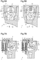
Fig. 6A is a diagram showing the locked state; -
Fig. 6B is a diagram showing the unlocked state; -
Fig. 7A is a diagram showing the locked state of the key interlock; -
Fig. 7B is a diagram of the unlocked state of the key interlock; -
Fig. 8 is a perspective view of the steering lock device from which the key interlock unit is removed; -
Fig. 9 is a front view of the camshaft; and -
Fig. 10 is a partially perspective view of the camshaft showing an interlock cam. - One embodiment of a steering lock device will now be described.
-
Fig. 1 illustrates an example of asteering lock device 1 that is configured to lock a steering wheel (not shown) to disable a steering operation of a vehicle. Thesteering lock device 1 includes ahousing 2, which may be referred to as the lock body, and acover 3. Thehousing 2 is formed from, for example, a magnesium alloy. Thehousing 2 includes a tubular portion, which has a longitudinal axis and two open ends, and a box-shaped portion 11, which has an opening in a side surface of the tubular portion. Thehousing 2 includes asupport portion 12, which is opposite to the box-shaped portion 11. Thesupport portion 12 may include a column support surface that is concaved in conformance with a convex outer surface of asteering column 5, which rotatably accommodates a steering shaft 4. Thecover 3 is formed from, for example, a zinc alloy and is shaped to close the opening of the box-shapedportion 11. Thecover 3 is fixed to thehousing 2 by a plurality of press-fit pins 6. Thesteering lock device 1 is fitted to thesteering column 5 by thesupport portion 12 of thehousing 2 and fixed to thesteering column 5 by a bracket (not shown). - As shown in
Figs. 1 and3 , thehousing 2 includes anopening 13 that is located in one end in the longitudinal direction (X-axis direction). Akey cylinder 7, which is inserted into theopening 13 and coupled to thehousing 2, is operated by amechanical key 80. Anignition switch 8, which is coupled to the other end of thehousing 2 in the longitudinal direction, switches the power state (vehicle power state) in accordance with the operation position of thekey cylinder 7. Thehousing 2 includes aninterlock attachment portion 14, which opens in a side surface of the box-shapedportion 11 and serves as a portion to which akey interlock unit 9 is attached. Thekey interlock unit 9 performs a key interlock that disables removal of the mechanical key 80 from thekey cylinder 7 unless ashift lever 81 is shifted to a parking position. - As shown in
Fig. 3 , thesteering lock device 1 includes alock mechanism 21 that locks and unlocks the steering operation by engaging with the steering shaft 4 and disengaging from the steering shaft 4. In the illustrated example, thelock mechanism 21 includes alock bar 22, which engages the steering shaft 4 to lock the steering shaft 4, alock stopper 23, which is coupled to thelock bar 22, and acamshaft 24, which is rotated when the mechanical key 80 operated in thekey cylinder 7. Thehousing 2 includes acomponent receptacle 26 that accommodates thelock bar 22, thelock stopper 23, and thecamshaft 24. A plurality (three in illustrated example) ofsupport walls 27 is arranged in thecomponent receptacle 26 next to one another in the longitudinal direction of thehousing 2 to separate the empty space of thecomponent receptacle 26. Each of thesupport walls 27 includes anarcuate groove 28, in which thecamshaft 24 is rotatably located. Additionally, a portion of thecomponent receptacle 26 defines anaccommodation space 29 that accommodates at least a portion of thekey interlock unit 9 in theinterlock attachment portion 14. - The
lock stopper 23 is plate-shaped and includes twoside walls 31, which are spaced apart from each other in a width-wise direction (Y-axis direction) of thehousing 2. Theside walls 31 are partially inserted into two guides 32 (Fig. 3 shows only one) located in an inner wall surface of thehousing 2. This couples thelock stopper 23 in a manner allowing for linear reciprocation of thelock stopper 23 along theguides 32. An urgingmember 33, which is, for example, a coil spring, is located between thecover 3 and thelock stopper 23 to urge thelock stopper 23 in a locking direction (negative side of Z-axis direction). Thelock stopper 23 has ahole 34, which accommodates one end of the urgingmember 33. The other end of the urgingmember 33 is supported by an inner surface of thecover 3. - As shown in
Figs. 2 and3 , thecamshaft 24 includes alock actuation cam 41, which has the form of a cam and actuates thelock stopper 23 in the locking direction or the unlocking direction. Thelock actuation cam 41 radially projects from ashaft portion 42, which may be a rod-shaped portion of thecamshaft 24. Thecamshaft 24 includes aninterlock cam 43, which corresponds to a cam-shaped projection that actuates thekey interlock unit 9. Theinterlock cam 43 radially projects from theshaft portion 42. Thelock actuation cam 41 and theinterlock cam 43 are located at different positions in an axial direction of thecamshaft 24 and symmetrical about an axis L1 of thecamshaft 24. Thecamshaft 24 includes acounterweight 44 that obtains the balance of thecamshaft 24 in a direction extending about the axis L1 (direction indicated by arrow R inFig. 3 ). Thecounterweight 44 radially projects from theshaft portion 42. Thecounterweight 44 and theinterlock cam 43 are located at substantially the same position in the axial direction and symmetrical about the axis L1. Thecamshaft 24 has an end that is located at a side of the key cylinder 7 (positive side of X-axis direction) and has an elongatedhole 45. Thekey cylinder 7 is coupled to theelongated hole 45. - As shown in
Figs. 3 ,4 , and6 , when thesteering lock device 1 is assembled, thecamshaft 24 is rotatably located between theside walls 31 of thelock stopper 23. Thelock stopper 23 includes acontact portion 51. Thelock actuation cam 41 is in contact with thecontact portion 51 from a side opposite to the urgingmember 33. Theinterlock cam 43 is directed to theinterlock attachment portion 14, which is the opening located in the side surface of thehousing 2. Thelock actuation cam 41 is located at a position that differs from the position corresponding to theinterlock attachment portion 14 in the axial direction of thecamshaft 24. - As shown in
Figs. 3 and4 , the basal end of thelock bar 22, which has the form of a polygonal rod, includes arecess 52. Thelock stopper 23 includes anengagement portion 53. Engagement of theengagement portion 53 with therecess 52 couples thelock bar 22 and thelock stopper 23 in a manner integrally movable in the locking direction and the unlocking direction. Thehousing 2 includes ahole 54 that opens in a curved surface of thesupport portion 12. When thesteering lock device 1 is assembled, the distal end oflock bar 22 is arranged to be able to project out of thehole 54 and retract into the hole 54 (refer toFig. 8 ). - As shown in
Fig. 5 , thekey interlock unit 9 includes acase 61, asolenoid 62 accommodated in thecase 61, and alink 63 coupled to thesolenoid 62. In the illustrated example, it is preferred that thecase 61 and thelink 63 be formed from a synthetic resin to reduce the weight. In some embodiments, thesolenoid 62 may be a known self-sustaining solenoid. Thekey interlock unit 9 is attached to theinterlock attachment portion 14 so that thelink 63 is opposed to theinterlock cam 43 in the width-wise direction (Y-axis direction) of thehousing 2. Thesolenoid 62 includes aplunger 64, which is coupled to the basal end of thelink 63. Thelink 63 is urged by atorsion spring 65 to be located in a region where the distal end of thelink 63 interferes with theinterlock cam 43. When thelink 63 is moved against the urging force of thetorsion spring 65 so that theplunger 64 projects, the distal end of thelink 63 is allowed to move out of the region where the distal end of thelink 63 interferes with theinterlock cam 43. - Locking and unlocking of the steering operation performed by the
steering lock device 1 will now be described. - As shown in
Fig. 6A , when thecamshaft 24 is rotated in a locking direction (direction indicated by arrow R1 inFig. 6A ), for example, by movement of thekey cylinder 7 to an IG OFF position, the urging force of the urgingmember 33 moves thelock bar 22 and thelock stopper 23 in a locking direction (direction indicated by arrow T1 inFig. 6A ). Consequently, thelock bar 22 projects out of thehole 54 of thehousing 2 and engages the steering shaft 4 to disable rotation of the steering shaft 4. This sets thesteering lock device 1 to the locked state. - As shown in
Fig. 6B , when thecamshaft 24 is rotated in an unlocking direction (direction indicated by arrow P2 inFig. 6B ), for example, by movement of thekey cylinder 7 to an ACC ON position or an IG ON position, thelock actuation cam 41 comes into contact with thecontact portion 51 and pushes thelock stopper 23 toward thecover 3. This moves thelock bar 22 and thelock stopper 23 against the urging force of the urgingmember 33 in an unlocking direction (direction indicated by arrow T2 inFig. 6B ). Consequently, thelock bar 22 is retracted into thehousing 2 and disengaged from the steering shaft 4. This sets thesteering lock device 1 to the unlocked state. - The key interlock performed by the
steering lock device 1 will now be described. - As shown in
Fig. 7A , when theshift lever 81 is shifted to a position other than the parking position, thesolenoid 62 is energized to restrict movement of theplunger 64, that is, movement of thelink 63. In this state, if the driver attempts to move thekey cylinder 7 from the ACC ON position to the IG OFF position, theinterlock cam 43 comes into contact with the distal end of thelink 63, the movement of which is restricted. This restricts further rotation. Therefore, when theshift lever 81 is not shifted to the parking position, thekey cylinder 7 cannot be moved to the IG OFF position and the mechanical key 80 cannot be removed from thekey cylinder 7. - As shown in
Fig. 7B , when theshift lever 81 is shifted to the parking position, the energization of thesolenoid 62 is stopped to allow for the movement of theplunger 64, that is, the movement of thelink 63. In this state, if the driver tries moving thekey cylinder 7 from the ACC ON position to the IG OFF position, theinterlock cam 43 pushes down thelink 63 against the urging force of thetorsion spring 65 and thekey cylinder 7 is rotated to the IG OFF position. Therefore, when theshift lever 81 is shifted to the parking position, thekey cylinder 7 is movable to the IG OFF position and themechanical key 80 is removable from thekey cylinder 7. - If a third party tampers with the
steering lock device 1 to switch thesteering lock device 1 from the locked state to the unlocked state, the third party may break thekey interlock unit 9 attached to thehousing 2 with a tool or the like. In particular, when thekey interlock unit 9 is formed from a synthetic resin, thekey interlock unit 9 is more vulnerable to tampering than other components. - As shown in
Fig. 8 , when thekey interlock unit 9 is removed, theinterlock cam 43 is exposed from the interlock attachment portion 14 (housing 2). When themechanical key 80 is removed in the locked state, rotation of thecamshaft 24, which is connected to thekey cylinder 7, is restricted. However, in order to rotate thecamshaft 24 in the unlocking direction (R2 direction, refer toFig. 6B ), the third party may apply a load to theinterlock cam 43 with a tool or the like to rotate the portion corresponding to thelock actuation cam 41, for example, by twisting theshaft portion 42 and plastically deforming thecamshaft 24. - In this regard, as shown in
Figs. 9 and 10 , thecamshaft 24 is configured so that theinterlock cam 43 is separated from theshaft portion 42 if a load that exceeds predetermined strength acts on theinterlock cam 43 in the locked state. In this specification, the load exceeding the predetermined strength may be a load that rotates thelock actuation cam 41 and disengages thelock bar 22 from the steering shaft 4. - More specifically, the
interlock cam 43 includes afirst wall 71, twosecond walls 72, and athird wall 73. Thefirst wall 71 extends radially from theshaft portion 42 of thecamshaft 24 and in the axial direction. Thesecond walls 72 radially extend from theshaft portion 42 and are connected to two opposite ends of thefirst wall 71. Thethird wall 73 is connected to the distal end of each of thefirst wall 71 and thesecond walls 72. More specifically, the basal ends of thefirst wall 71 and thesecond walls 72 correspond to where theinterlock cam 43 and theshaft portion 42 are connected to each other. - The
first wall 71 is plate-shaped and bent in the locking direction of thecamshaft 24 toward a radially outer side. Each of thesecond walls 72, the thickness of which extends in the circumferential direction, is sectoral so that the thickness is gradually reduced toward a radially inner side. Thethird wall 73 has the form of an arcuate plate that extends along the outer edge of each of thesecond walls 72. - The basal end of each of the
second walls 72 is, for example, machined to be partially cut away defining a recess or acutaway portion 74. To facilitate understanding, inFig. 9 , the double-dashed lines show wall surfaces of thesecond walls 72 before thecutaway portions 74 are formed. Thecutaway portions 74 locally reduce the strength of the part connecting theinterlock cam 43 with theshaft portion 42. When the load exceeding the predetermined strength acts on theinterlock cam 43, theinterlock cam 43 is separated from theshaft portion 42. Thecutaway portions 74 each function as a low-strength portion. - The measured thickness of the
cutaway portions 74, which extends in the circumferential direction, is determined in advance based on tests, simulations, or the like. The thickness is set so that theinterlock cam 43 is separated from the shaft portion 42 (camshaft 24), for example, when receiving a load that is less than a first predetermined load strength and greater than a second predetermined load strength. In the illustrated example, the first load strength corresponds to a load that plastically twists and deforms theshaft portion 42 when rotation of thecamshaft 24 is restricted by thekey cylinder 7 that is located in the IG OFF position. The second load strength corresponds to a load that acts from thelink 63 of thekey interlock unit 9 on theinterlock cam 43 when the driver uses the mechanical key 80 to rotate thekey cylinder 7 to the IG OFF position with theshift lever 81 located at a position other than the parking position (refer toFig. 7A ). - In the illustrated example, the
camshaft 24 may be manufactured, for example, by casting. Theshaft portion 42 and theinterlock cam 43 of thecamshaft 24 may be formed in a single piece. In the illustrated example, thecamshaft 24 including theinterlock cam 43, theshaft portion 42, and thelock actuation cam 41 is a single piece. When manufacturing theinterlock cam 43, thecutaway portion 74 is formed in each of thesecond walls 72, for example, by machining so that each of thesecond walls 72 has the shape described above. - The operation and advantages of the
steering lock device 1 will now be described. - (1) The
camshaft 24 is configured so that theinterlock cam 43 is separated from theshaft portion 42 when the load exceeding the predetermined strength acts on theinterlock cam 43 in the locked state. Thus, when a third party tampers with thesteering lock device 1 by applying a load to theinterlock cam 43 to rotate thecamshaft 24, theinterlock cam 43 is separated from theshaft portion 42 before rotation of thelock actuation cam 41 disengages thelock bar 22 from the steering shaft 4. Thus, the load cannot be applied to theinterlock cam 43 to rotate thecamshaft 24. This obviates unauthorized unlocking.
In the present embodiment, thekey interlock unit 9 is formed from a synthetic resin. Thekey interlock unit 9 is attached to thehousing 2. With this structure, there is a high probability that thekey interlock unit 9 is tampered with from outside thekey interlock unit 9 to expose theinterlock cam 43 from theinterlock attachment portion 14. However, theinterlock cam 43 is configured to be separated from theshaft portion 42 when a large load acts on theinterlock cam 43. This obviates the tampering attempted on thekey interlock unit 9 from unauthorized unlocking. Thus, the resistance to tempering is improved. - (2) The
camshaft 24 includes theshaft portion 42 and theinterlock cam 43, which are formed integrally with each other. Additionally, the basal end of each of thesecond walls 72 includes thecutaway portion 74. This allows theinterlock cam 43 to break from thecutaway portion 74 and separated from theshaft portion 42 when the load exceeding the predetermined strength acts on theinterlock cam 43. Thus, theinterlock cam 43 is configured to be separated from theshaft portion 42 without increasing the number of components. - (3) The
case 61 and thelink 63 of thekey interlock unit 9 are formed from a synthetic resin. This reduces the weight of thesteering lock device 1. - It should be apparent to those skilled in the art that the present invention may be embodied in many other specific forms without departing from the scope of the invention. Particularly, it should be understood that the present invention may be embodied in the following forms.
- In the embodiment, the predetermined strength of a load that separates the
interlock cam 43 from the shaft portion 42 (minimum value of load needed to separateinterlock cam 43 from shaft portion 42) is set to be less than the first load strength, which plastically twists and deforms theshaft portion 42. However, for example, when thecamshaft 24 is designed so that theelongated hole 45 is plastically deformed before the plastically twisting and deformation of theshaft portion 42, the predetermined strength may be set to be less than the minimum load capable of plastically deforming theelongated hole 45. The predetermined strength only needs to be set so that theinterlock cam 43 is separated from theshaft portion 42 before rotation of thelock actuation cam 41 disengages thelock bar 22 from the steering shaft 4. The predetermined strength may be changed taken into consideration the strength of other portions of thecamshaft 24 and the strength of thekey cylinder 7 coupled to thecamshaft 24. - In the embodiment, the
interlock cam 43 is configured to be separated from thecamshaft 24. However, instead of or in addition to theinterlock cam 43, thecamshaft 24 may be configured so that, for example, thecounterweight 44 is separated from thecamshaft 24. Alternatively, when thecamshaft 24 includes another projection radially projecting from theshaft portion 42 in addition to thelock actuation cam 41, theinterlock cam 43, and thecounterweight 44, thecamshaft 24 may be configured to allow for separation of the projection. It is preferred that the projection configured to be separated from thecamshaft 24 be accommodated in thehousing 2 when thekey cylinder 7, theignition switch 8, and thekey interlock unit 9 are coupled to thehousing 2. However, the projection may be exposed from thehousing 2. When thecamshaft 24 includes one or more projections configure to be separated, theinterlock cam 43 does not have to be configured to be separated from theshaft portion 42. - In the embodiment, the
interlock cam 43 is formed integrally with theshaft portion 42. Instead, for example, when theinterlock cam 43 and theshaft portion 42 are manufactured as separate members, theinterlock cam 43 may be fixed to theshaft portion 42 by welding theinterlock cam 43 and theshaft portion 42 or by using a projection and a recess to fit together theinterlock cam 43 and theshaft portion 42. - In the embodiment, the
interlock cam 43 includes the first tothird walls 71 to 73. However, the shape of theinterlock cam 43 may be changed. For example, theinterlock cam 43 may be box-shaped. - In the embodiment, the basal end of each of the
second walls 72 includes thecutaway portion 74, which functions as the low-strength portion that reduces the strength of the part connecting theinterlock cam 43 and theshaft portion 42. However, the low-strength portion is not limited to thecutaway portion 74 and may be changed. For example, the basal end of thefirst wall 71 may include a cutaway portion functioning as the low-strength portion. Alternatively, for example, the basal end of thefirst wall 71 or the basal ends of thesecond walls 72 may include a number of small holes functioning as the low-strength portion. - The
interlock cam 43 may be omitted from thecamshaft 24. Thekey interlock unit 9 may be omitted from thesteering lock device 1. - The
solenoid 62 may be a different type of solenoid such as a pull solenoid. - The
case 61 and thelink 63 of thekey interlock unit 9 may be formed from a material other than a synthetic resin. Even if thecase 61 is not formed from a synthetic resin, when thekey interlock unit 9 is configured to be separately attached to thehousing 2, there is a high probability that a third party does not tamper with thehousing 2 but tampers with thekey interlock unit 9. Theinterlock cam 43 is configured to be separated from theshaft portion 42 when the load exceeding the predetermined strength acts on theinterlock cam 43. Thus, the resistance to the tampering is improved. - In the embodiment, the shape of the
housing 2 may be changed. For example, theinterlock attachment portion 14 may be located closer to theopening 13. Thekey interlock unit 9 may be located closer to thekey cylinder 7 than thelock mechanism 21. - In the embodiment, the structure of the
lock mechanism 21 may be changed as long as the steering operation is restricted. For example, thelock stopper 23 may be omitted. In this case, thecamshaft 24 may be configured to directly actuate thelock bar 22. - In the embodiment, the
steering lock device 1 may be of a mechanically-driven type or an electrically-drive type. - The present disclosure includes the following implementation(s).
- [Implementation 1] A steering lock device in which the predetermined strength is less than a first load strength, which plastically twists and deforms the shaft portion when rotation of the camshaft is restricted by movement of the key cylinder to the IG OFF position, and is greater than a second load strength, which acts on the interlock cam from the key interlock unit when one attempts to rotate the mechanical key to the IG OFF position in a state in which the
shift lever 81 is not shifted to the parking position. This structure obtains the key interlock function. Also, with this structure, when a third party who is attempting unauthorized unlocking applies a load exceeding the predetermined strength to the interlock cam with a tool or the like, the interlock cam is separated. This obviates unauthorized unlocking. - The present examples and embodiments are to be considered as illustrative and not restrictive, and the invention is not to be limited to the details given herein, but may be modified within the scope and equivalence of the appended claims. For example, one or more of the components may be omitted from the components described in the embodiments (or one or more aspects thereof). Components in different embodiments may be appropriately combined.
Claims (5)
- A steering lock device (1) comprising:a camshaft (24) including a shaft portion (42) having an axis (L1), a lock actuation cam (41) that radially projects from a first position of the shaft portion (42) in an axial direction, and a projection (43) that radially projects from a second position of the shaft portion (42) that differs from the first position in the axial direction, wherein the camshaft (24) is rotated about the axis (L1) when a key cylinder (7) is operated by a mechanical key (80);a housing (2) that rotatably accommodates the camshaft (24); anda lock bar (22) that is moved by the lock actuation cam (41) in a locking direction or an unlocking direction when the camshaft (24) is rotated, whereinwhen the lock bar (22) is moved in the locking direction, the lock bar (22) engages a steering shaft (4) to lock the steering shaft (4),when the lock bar (22) is moved in the unlocking direction, the lock bar (22) is disengaged from the steering shaft (4) to unlock the steering shaft (4), andwhen the lock bar (22) locks the steering shaft (4), the camshaft (24) is configured so that the projection (43) is separated from the shaft portion (42) if a load exceeding a predetermined strength acts on the projection (43) of the camshaft (24), wherein the predetermined strength rotates the lock actuation cam (41) to disengage the lock bar (22) from the steering shaft (4).
- The steering lock device (1) according to claim 1, wherein
the shaft portion (42) and the projection (43) of the camshaft (24) are formed integrally with each other,
the camshaft (24) includes a low-strength portion (74) located where the projection (43) and the shaft portion (42) are connected to each other. - The steering lock device (1) according to claim 1 or 2, wherein
the steering lock device (1) is used with a vehicle shift lever (81) that is shifted to a parking position and a non-parking position,
the key cylinder (7) is coupled to the housing (2),
the housing (2) includes an interlock attachment portion (14) configured to attach a key interlock unit (9) that prohibits removal of the mechanical key (80) from the key cylinder (7) unless the shift lever (81) is shifted to the parking position, and
the projection (43) includes a cam-shaped interlock cam (43) that actuates the key interlock unit (9). - The steering lock device (1) according to claim 3, wherein the key interlock unit (9) includes a synthetic resin case (61).
- The steering lock device (1) according to any one of claims 1 to 4, wherein
the camshaft (24) includes a breakable portion (74) that is locally narrow or thin,
the breakable portion (74) is located at or proximate to a boundary of the shaft portion (42) and the projection (43), and
when the camshaft (24) receives a load exceeding the predetermined strength, the breakable portion (74) is configured to break so that the projection (43) is separated from the shaft portion (42) but the lock actuation cam (41) is not separated from the shaft portion (42).
Applications Claiming Priority (1)
| Application Number | Priority Date | Filing Date | Title |
|---|---|---|---|
| JP2016111254A JP6166427B1 (en) | 2016-06-02 | 2016-06-02 | Steering lock device |
Publications (2)
| Publication Number | Publication Date |
|---|---|
| EP3251901A1 true EP3251901A1 (en) | 2017-12-06 |
| EP3251901B1 EP3251901B1 (en) | 2021-04-28 |
Family
ID=58800714
Family Applications (1)
| Application Number | Title | Priority Date | Filing Date |
|---|---|---|---|
| EP17173211.8A Active EP3251901B1 (en) | 2016-06-02 | 2017-05-29 | Steering lock device |
Country Status (5)
| Country | Link |
|---|---|
| US (1) | US10017151B2 (en) |
| EP (1) | EP3251901B1 (en) |
| JP (1) | JP6166427B1 (en) |
| CN (1) | CN107458344B (en) |
| CA (1) | CA2968551C (en) |
Families Citing this family (2)
| Publication number | Priority date | Publication date | Assignee | Title |
|---|---|---|---|---|
| CN109724461B (en) * | 2018-12-19 | 2021-07-30 | 湖北航天飞行器研究所 | Locking mechanism of vehicle-mounted launching system |
| CN114027591B (en) * | 2020-09-09 | 2024-02-20 | 联扬塑胶(深圳)有限公司 | Toggle unlocking buckle device |
Citations (5)
| Publication number | Priority date | Publication date | Assignee | Title |
|---|---|---|---|---|
| US4143528A (en) * | 1976-10-01 | 1979-03-13 | Neiman S.A. | Anti-theft locking devices |
| JPS58180348A (en) * | 1982-04-16 | 1983-10-21 | Nissan Motor Co Ltd | Steering gear lock |
| US20020148262A1 (en) * | 2001-04-11 | 2002-10-17 | Masanari Okuno | Apparatus for starting vehicle engine |
| JP2007125970A (en) * | 2005-11-02 | 2007-05-24 | Alpha Corp | Locking device |
| US20150158459A1 (en) * | 2013-12-11 | 2015-06-11 | Kabushiki Kaisha Tokai Rika Denki Seisakusho | Steering lock device |
Family Cites Families (10)
| Publication number | Priority date | Publication date | Assignee | Title |
|---|---|---|---|---|
| US3442102A (en) * | 1966-12-14 | 1969-05-06 | Gen Motors Corp | Cylinder lock actuator |
| FR2582751B1 (en) * | 1985-05-31 | 1988-05-06 | Nacam | TORQUE LIMITING ROTATION LOCKING DEVICE FOR A STEERING COLUMN OF A MOTOR VEHICLE |
| JP3527394B2 (en) * | 1997-09-29 | 2004-05-17 | 株式会社東海理化電機製作所 | Steering lock device |
| JP2001080383A (en) * | 1999-07-13 | 2001-03-27 | Tokai Rika Co Ltd | Shift lever device |
| EP1378406B1 (en) * | 2002-05-29 | 2006-09-06 | Kabushiki Kaisha Tokai Rika Denki Seisakusho | Apparatus for restricting activation of engine starting system |
| JP3990224B2 (en) * | 2002-08-09 | 2007-10-10 | 株式会社ホンダロック | Steering lock device |
| JP4100570B2 (en) * | 2003-10-03 | 2008-06-11 | 本田技研工業株式会社 | Vehicle locking device |
| JP2007269176A (en) * | 2006-03-31 | 2007-10-18 | Alpha Corp | Steering lock device |
| JP5809831B2 (en) * | 2011-04-04 | 2015-11-11 | 株式会社アルファ | Steering lock device |
| JP5770515B2 (en) * | 2011-04-04 | 2015-08-26 | 株式会社アルファ | Steering lock device |
-
2016
- 2016-06-02 JP JP2016111254A patent/JP6166427B1/en active Active
-
2017
- 2017-05-24 CN CN201710374466.1A patent/CN107458344B/en active Active
- 2017-05-25 CA CA2968551A patent/CA2968551C/en not_active Expired - Fee Related
- 2017-05-29 US US15/607,532 patent/US10017151B2/en active Active
- 2017-05-29 EP EP17173211.8A patent/EP3251901B1/en active Active
Patent Citations (6)
| Publication number | Priority date | Publication date | Assignee | Title |
|---|---|---|---|---|
| US4143528A (en) * | 1976-10-01 | 1979-03-13 | Neiman S.A. | Anti-theft locking devices |
| JPS58180348A (en) * | 1982-04-16 | 1983-10-21 | Nissan Motor Co Ltd | Steering gear lock |
| US20020148262A1 (en) * | 2001-04-11 | 2002-10-17 | Masanari Okuno | Apparatus for starting vehicle engine |
| JP2007125970A (en) * | 2005-11-02 | 2007-05-24 | Alpha Corp | Locking device |
| US20150158459A1 (en) * | 2013-12-11 | 2015-06-11 | Kabushiki Kaisha Tokai Rika Denki Seisakusho | Steering lock device |
| JP2015112987A (en) | 2013-12-11 | 2015-06-22 | 株式会社東海理化電機製作所 | Steering lock device |
Also Published As
| Publication number | Publication date |
|---|---|
| CN107458344B (en) | 2020-07-28 |
| JP2017217922A (en) | 2017-12-14 |
| JP6166427B1 (en) | 2017-07-19 |
| US10017151B2 (en) | 2018-07-10 |
| CA2968551C (en) | 2019-05-21 |
| US20170349140A1 (en) | 2017-12-07 |
| CN107458344A (en) | 2017-12-12 |
| EP3251901B1 (en) | 2021-04-28 |
| CA2968551A1 (en) | 2017-12-02 |
Similar Documents
| Publication | Publication Date | Title |
|---|---|---|
| EP1845223B1 (en) | Key cylinder | |
| US6810700B2 (en) | Apparatus for starting vehicle engine | |
| JP5431250B2 (en) | Key interlock device | |
| EP2517935A1 (en) | Steering locking device | |
| EP2694336B1 (en) | Steering lock device | |
| EP2694337B1 (en) | Steering lock device | |
| EP3251901B1 (en) | Steering lock device | |
| EP0335712A2 (en) | A steering column shaft locking device for an automotive vehicle | |
| CN109305123B (en) | Steering lock device | |
| JP4694384B2 (en) | Steering lock device | |
| EP2842817B1 (en) | Steering lock device | |
| EP3192707B1 (en) | Steering lock device and assembling method of steering lock device | |
| EP2842818B1 (en) | Steering lock device | |
| EP3604048B1 (en) | Steering lock device | |
| EP3192708A1 (en) | Steering lock device | |
| CN114846210B (en) | Lock for motor vehicle | |
| JP7175176B2 (en) | electric steering lock device | |
| JP7175175B2 (en) | electric steering lock device | |
| EP3199412B1 (en) | Bracket for a vehicle antitheft device | |
| GB2556426A (en) | Steering lock device | |
| JP2013063725A (en) | Steering lock device |
Legal Events
| Date | Code | Title | Description |
|---|---|---|---|
| PUAI | Public reference made under article 153(3) epc to a published international application that has entered the european phase |
Free format text: ORIGINAL CODE: 0009012 |
|
| STAA | Information on the status of an ep patent application or granted ep patent |
Free format text: STATUS: THE APPLICATION HAS BEEN PUBLISHED |
|
| AK | Designated contracting states |
Kind code of ref document: A1 Designated state(s): AL AT BE BG CH CY CZ DE DK EE ES FI FR GB GR HR HU IE IS IT LI LT LU LV MC MK MT NL NO PL PT RO RS SE SI SK SM TR |
|
| AX | Request for extension of the european patent |
Extension state: BA ME |
|
| STAA | Information on the status of an ep patent application or granted ep patent |
Free format text: STATUS: REQUEST FOR EXAMINATION WAS MADE |
|
| 17P | Request for examination filed |
Effective date: 20180606 |
|
| RBV | Designated contracting states (corrected) |
Designated state(s): AL AT BE BG CH CY CZ DE DK EE ES FI FR GB GR HR HU IE IS IT LI LT LU LV MC MK MT NL NO PL PT RO RS SE SI SK SM TR |
|
| STAA | Information on the status of an ep patent application or granted ep patent |
Free format text: STATUS: EXAMINATION IS IN PROGRESS |
|
| 17Q | First examination report despatched |
Effective date: 20191024 |
|
| GRAP | Despatch of communication of intention to grant a patent |
Free format text: ORIGINAL CODE: EPIDOSNIGR1 |
|
| STAA | Information on the status of an ep patent application or granted ep patent |
Free format text: STATUS: GRANT OF PATENT IS INTENDED |
|
| INTG | Intention to grant announced |
Effective date: 20201117 |
|
| GRAS | Grant fee paid |
Free format text: ORIGINAL CODE: EPIDOSNIGR3 |
|
| GRAA | (expected) grant |
Free format text: ORIGINAL CODE: 0009210 |
|
| STAA | Information on the status of an ep patent application or granted ep patent |
Free format text: STATUS: THE PATENT HAS BEEN GRANTED |
|
| AK | Designated contracting states |
Kind code of ref document: B1 Designated state(s): AL AT BE BG CH CY CZ DE DK EE ES FI FR GB GR HR HU IE IS IT LI LT LU LV MC MK MT NL NO PL PT RO RS SE SI SK SM TR |
|
| REG | Reference to a national code |
Ref country code: GB Ref legal event code: FG4D |
|
| REG | Reference to a national code |
Ref country code: CH Ref legal event code: EP |
|
| REG | Reference to a national code |
Ref country code: DE Ref legal event code: R096 Ref document number: 602017037450 Country of ref document: DE |
|
| REG | Reference to a national code |
Ref country code: AT Ref legal event code: REF Ref document number: 1386731 Country of ref document: AT Kind code of ref document: T Effective date: 20210515 |
|
| REG | Reference to a national code |
Ref country code: IE Ref legal event code: FG4D |
|
| PGFP | Annual fee paid to national office [announced via postgrant information from national office to epo] |
Ref country code: FR Payment date: 20210607 Year of fee payment: 5 |
|
| REG | Reference to a national code |
Ref country code: LT Ref legal event code: MG9D |
|
| PGFP | Annual fee paid to national office [announced via postgrant information from national office to epo] |
Ref country code: GB Payment date: 20210623 Year of fee payment: 5 |
|
| REG | Reference to a national code |
Ref country code: AT Ref legal event code: MK05 Ref document number: 1386731 Country of ref document: AT Kind code of ref document: T Effective date: 20210428 |
|
| PG25 | Lapsed in a contracting state [announced via postgrant information from national office to epo] |
Ref country code: HR Free format text: LAPSE BECAUSE OF FAILURE TO SUBMIT A TRANSLATION OF THE DESCRIPTION OR TO PAY THE FEE WITHIN THE PRESCRIBED TIME-LIMIT Effective date: 20210428 Ref country code: BG Free format text: LAPSE BECAUSE OF FAILURE TO SUBMIT A TRANSLATION OF THE DESCRIPTION OR TO PAY THE FEE WITHIN THE PRESCRIBED TIME-LIMIT Effective date: 20210728 Ref country code: AT Free format text: LAPSE BECAUSE OF FAILURE TO SUBMIT A TRANSLATION OF THE DESCRIPTION OR TO PAY THE FEE WITHIN THE PRESCRIBED TIME-LIMIT Effective date: 20210428 Ref country code: NL Free format text: LAPSE BECAUSE OF FAILURE TO SUBMIT A TRANSLATION OF THE DESCRIPTION OR TO PAY THE FEE WITHIN THE PRESCRIBED TIME-LIMIT Effective date: 20210428 Ref country code: FI Free format text: LAPSE BECAUSE OF FAILURE TO SUBMIT A TRANSLATION OF THE DESCRIPTION OR TO PAY THE FEE WITHIN THE PRESCRIBED TIME-LIMIT Effective date: 20210428 Ref country code: LT Free format text: LAPSE BECAUSE OF FAILURE TO SUBMIT A TRANSLATION OF THE DESCRIPTION OR TO PAY THE FEE WITHIN THE PRESCRIBED TIME-LIMIT Effective date: 20210428 |
|
| PG25 | Lapsed in a contracting state [announced via postgrant information from national office to epo] |
Ref country code: LV Free format text: LAPSE BECAUSE OF FAILURE TO SUBMIT A TRANSLATION OF THE DESCRIPTION OR TO PAY THE FEE WITHIN THE PRESCRIBED TIME-LIMIT Effective date: 20210428 Ref country code: GR Free format text: LAPSE BECAUSE OF FAILURE TO SUBMIT A TRANSLATION OF THE DESCRIPTION OR TO PAY THE FEE WITHIN THE PRESCRIBED TIME-LIMIT Effective date: 20210729 Ref country code: IS Free format text: LAPSE BECAUSE OF FAILURE TO SUBMIT A TRANSLATION OF THE DESCRIPTION OR TO PAY THE FEE WITHIN THE PRESCRIBED TIME-LIMIT Effective date: 20210828 Ref country code: PL Free format text: LAPSE BECAUSE OF FAILURE TO SUBMIT A TRANSLATION OF THE DESCRIPTION OR TO PAY THE FEE WITHIN THE PRESCRIBED TIME-LIMIT Effective date: 20210428 Ref country code: PT Free format text: LAPSE BECAUSE OF FAILURE TO SUBMIT A TRANSLATION OF THE DESCRIPTION OR TO PAY THE FEE WITHIN THE PRESCRIBED TIME-LIMIT Effective date: 20210830 Ref country code: NO Free format text: LAPSE BECAUSE OF FAILURE TO SUBMIT A TRANSLATION OF THE DESCRIPTION OR TO PAY THE FEE WITHIN THE PRESCRIBED TIME-LIMIT Effective date: 20210728 Ref country code: RS Free format text: LAPSE BECAUSE OF FAILURE TO SUBMIT A TRANSLATION OF THE DESCRIPTION OR TO PAY THE FEE WITHIN THE PRESCRIBED TIME-LIMIT Effective date: 20210428 Ref country code: SE Free format text: LAPSE BECAUSE OF FAILURE TO SUBMIT A TRANSLATION OF THE DESCRIPTION OR TO PAY THE FEE WITHIN THE PRESCRIBED TIME-LIMIT Effective date: 20210428 |
|
| REG | Reference to a national code |
Ref country code: NL Ref legal event code: MP Effective date: 20210428 |
|
| REG | Reference to a national code |
Ref country code: CH Ref legal event code: PL |
|
| PG25 | Lapsed in a contracting state [announced via postgrant information from national office to epo] |
Ref country code: SK Free format text: LAPSE BECAUSE OF FAILURE TO SUBMIT A TRANSLATION OF THE DESCRIPTION OR TO PAY THE FEE WITHIN THE PRESCRIBED TIME-LIMIT Effective date: 20210428 Ref country code: SM Free format text: LAPSE BECAUSE OF FAILURE TO SUBMIT A TRANSLATION OF THE DESCRIPTION OR TO PAY THE FEE WITHIN THE PRESCRIBED TIME-LIMIT Effective date: 20210428 Ref country code: LI Free format text: LAPSE BECAUSE OF NON-PAYMENT OF DUE FEES Effective date: 20210531 Ref country code: MC Free format text: LAPSE BECAUSE OF FAILURE TO SUBMIT A TRANSLATION OF THE DESCRIPTION OR TO PAY THE FEE WITHIN THE PRESCRIBED TIME-LIMIT Effective date: 20210428 Ref country code: LU Free format text: LAPSE BECAUSE OF NON-PAYMENT OF DUE FEES Effective date: 20210529 Ref country code: DK Free format text: LAPSE BECAUSE OF FAILURE TO SUBMIT A TRANSLATION OF THE DESCRIPTION OR TO PAY THE FEE WITHIN THE PRESCRIBED TIME-LIMIT Effective date: 20210428 Ref country code: CZ Free format text: LAPSE BECAUSE OF FAILURE TO SUBMIT A TRANSLATION OF THE DESCRIPTION OR TO PAY THE FEE WITHIN THE PRESCRIBED TIME-LIMIT Effective date: 20210428 Ref country code: EE Free format text: LAPSE BECAUSE OF FAILURE TO SUBMIT A TRANSLATION OF THE DESCRIPTION OR TO PAY THE FEE WITHIN THE PRESCRIBED TIME-LIMIT Effective date: 20210428 Ref country code: CH Free format text: LAPSE BECAUSE OF NON-PAYMENT OF DUE FEES Effective date: 20210531 Ref country code: RO Free format text: LAPSE BECAUSE OF FAILURE TO SUBMIT A TRANSLATION OF THE DESCRIPTION OR TO PAY THE FEE WITHIN THE PRESCRIBED TIME-LIMIT Effective date: 20210428 Ref country code: ES Free format text: LAPSE BECAUSE OF FAILURE TO SUBMIT A TRANSLATION OF THE DESCRIPTION OR TO PAY THE FEE WITHIN THE PRESCRIBED TIME-LIMIT Effective date: 20210428 |
|
| REG | Reference to a national code |
Ref country code: DE Ref legal event code: R097 Ref document number: 602017037450 Country of ref document: DE |
|
| REG | Reference to a national code |
Ref country code: BE Ref legal event code: MM Effective date: 20210531 |
|
| PLBE | No opposition filed within time limit |
Free format text: ORIGINAL CODE: 0009261 |
|
| STAA | Information on the status of an ep patent application or granted ep patent |
Free format text: STATUS: NO OPPOSITION FILED WITHIN TIME LIMIT |
|
| 26N | No opposition filed |
Effective date: 20220131 |
|
| PG25 | Lapsed in a contracting state [announced via postgrant information from national office to epo] |
Ref country code: IE Free format text: LAPSE BECAUSE OF NON-PAYMENT OF DUE FEES Effective date: 20210529 |
|
| PG25 | Lapsed in a contracting state [announced via postgrant information from national office to epo] |
Ref country code: IS Free format text: LAPSE BECAUSE OF FAILURE TO SUBMIT A TRANSLATION OF THE DESCRIPTION OR TO PAY THE FEE WITHIN THE PRESCRIBED TIME-LIMIT Effective date: 20210828 Ref country code: AL Free format text: LAPSE BECAUSE OF FAILURE TO SUBMIT A TRANSLATION OF THE DESCRIPTION OR TO PAY THE FEE WITHIN THE PRESCRIBED TIME-LIMIT Effective date: 20210428 |
|
| PG25 | Lapsed in a contracting state [announced via postgrant information from national office to epo] |
Ref country code: IT Free format text: LAPSE BECAUSE OF FAILURE TO SUBMIT A TRANSLATION OF THE DESCRIPTION OR TO PAY THE FEE WITHIN THE PRESCRIBED TIME-LIMIT Effective date: 20210428 Ref country code: BE Free format text: LAPSE BECAUSE OF NON-PAYMENT OF DUE FEES Effective date: 20210531 |
|
| GBPC | Gb: european patent ceased through non-payment of renewal fee |
Effective date: 20220529 |
|
| PG25 | Lapsed in a contracting state [announced via postgrant information from national office to epo] |
Ref country code: FR Free format text: LAPSE BECAUSE OF NON-PAYMENT OF DUE FEES Effective date: 20220531 |
|
| PG25 | Lapsed in a contracting state [announced via postgrant information from national office to epo] |
Ref country code: HU Free format text: LAPSE BECAUSE OF FAILURE TO SUBMIT A TRANSLATION OF THE DESCRIPTION OR TO PAY THE FEE WITHIN THE PRESCRIBED TIME-LIMIT; INVALID AB INITIO Effective date: 20170529 Ref country code: GB Free format text: LAPSE BECAUSE OF NON-PAYMENT OF DUE FEES Effective date: 20220529 |
|
| PG25 | Lapsed in a contracting state [announced via postgrant information from national office to epo] |
Ref country code: CY Free format text: LAPSE BECAUSE OF FAILURE TO SUBMIT A TRANSLATION OF THE DESCRIPTION OR TO PAY THE FEE WITHIN THE PRESCRIBED TIME-LIMIT Effective date: 20210428 |
|
| PGFP | Annual fee paid to national office [announced via postgrant information from national office to epo] |
Ref country code: DE Payment date: 20230404 Year of fee payment: 7 |
|
| PG25 | Lapsed in a contracting state [announced via postgrant information from national office to epo] |
Ref country code: MK Free format text: LAPSE BECAUSE OF FAILURE TO SUBMIT A TRANSLATION OF THE DESCRIPTION OR TO PAY THE FEE WITHIN THE PRESCRIBED TIME-LIMIT Effective date: 20210428 |