EP2011908A1 - Combined device for opening and feeding flock fibres to a carding machine - Google Patents
Combined device for opening and feeding flock fibres to a carding machine Download PDFInfo
- Publication number
- EP2011908A1 EP2011908A1 EP07111856A EP07111856A EP2011908A1 EP 2011908 A1 EP2011908 A1 EP 2011908A1 EP 07111856 A EP07111856 A EP 07111856A EP 07111856 A EP07111856 A EP 07111856A EP 2011908 A1 EP2011908 A1 EP 2011908A1
- Authority
- EP
- European Patent Office
- Prior art keywords
- fibres
- cylinders
- flock
- clothing
- cylinder
- Prior art date
- Legal status (The legal status is an assumption and is not a legal conclusion. Google has not performed a legal analysis and makes no representation as to the accuracy of the status listed.)
- Withdrawn
Links
- 238000009960 carding Methods 0.000 title claims abstract description 61
- 244000144992 flock Species 0.000 title claims abstract description 54
- 239000002657 fibrous material Substances 0.000 claims abstract description 10
- 239000000463 material Substances 0.000 claims description 32
- 230000000694 effects Effects 0.000 claims description 12
- 230000002093 peripheral effect Effects 0.000 claims description 10
- 210000003462 vein Anatomy 0.000 claims description 4
- 239000012535 impurity Substances 0.000 description 9
- 238000004519 manufacturing process Methods 0.000 description 7
- 230000008030 elimination Effects 0.000 description 6
- 238000003379 elimination reaction Methods 0.000 description 6
- 239000000835 fiber Substances 0.000 description 6
- 229920000742 Cotton Polymers 0.000 description 5
- 238000000034 method Methods 0.000 description 5
- 238000002360 preparation method Methods 0.000 description 5
- 238000004140 cleaning Methods 0.000 description 3
- 238000011144 upstream manufacturing Methods 0.000 description 3
- 230000006866 deterioration Effects 0.000 description 2
- 239000000428 dust Substances 0.000 description 2
- 230000001105 regulatory effect Effects 0.000 description 2
- 238000000926 separation method Methods 0.000 description 2
- 235000002566 Capsicum Nutrition 0.000 description 1
- 239000006002 Pepper Substances 0.000 description 1
- 235000016761 Piper aduncum Nutrition 0.000 description 1
- 235000017804 Piper guineense Nutrition 0.000 description 1
- 244000203593 Piper nigrum Species 0.000 description 1
- 235000008184 Piper nigrum Nutrition 0.000 description 1
- 230000001174 ascending effect Effects 0.000 description 1
- 230000015572 biosynthetic process Effects 0.000 description 1
- 230000006835 compression Effects 0.000 description 1
- 238000007906 compression Methods 0.000 description 1
- 230000001419 dependent effect Effects 0.000 description 1
- 238000007599 discharging Methods 0.000 description 1
- 238000012840 feeding operation Methods 0.000 description 1
- 238000003780 insertion Methods 0.000 description 1
- 230000037431 insertion Effects 0.000 description 1
- 238000010409 ironing Methods 0.000 description 1
- 239000010813 municipal solid waste Substances 0.000 description 1
- 238000007383 open-end spinning Methods 0.000 description 1
- 230000008092 positive effect Effects 0.000 description 1
- 238000009987 spinning Methods 0.000 description 1
Images

Classifications
-
- D—TEXTILES; PAPER
- D01—NATURAL OR MAN-MADE THREADS OR FIBRES; SPINNING
- D01G—PRELIMINARY TREATMENT OF FIBRES, e.g. FOR SPINNING
- D01G23/00—Feeding fibres to machines; Conveying fibres between machines
- D01G23/02—Hoppers; Delivery shoots
-
- D—TEXTILES; PAPER
- D01—NATURAL OR MAN-MADE THREADS OR FIBRES; SPINNING
- D01G—PRELIMINARY TREATMENT OF FIBRES, e.g. FOR SPINNING
- D01G9/00—Opening or cleaning fibres, e.g. scutching cotton
- D01G9/06—Opening or cleaning fibres, e.g. scutching cotton by means of toothed members
Definitions
- the present invention refers to the feeding line of carding machines by which the fibrous material coming from bales of raw fibres - for example cotton - is processed in a series of devices, currently known as battery line, until the flock fibres are produced that are fed in the form of a wadding mattress for carding in the carding machines.
- carding consists of passing the flock material onto a series of equipped surfaces, in other words equipped with a multitude of spikes, rotating at increasing peripheral speed.
- the fibrous material is opened in the form of single stretched out fibre, the dirt, like dust, short fibres and stubble are to a large extent eliminated, the fibres undergo mixing together and a band of non-twisted fibres is formed, to be sent to the subsequent processing stages.
- bales of cotton that are stretched out side-by-side on the floor to form a fibrous layer and are subjected to the action of a plucker 1 with one or more reels that crosses with back-and-forth motion the layer of bales that is progressively used up.
- a plucker 1 essentially has the task of opening, i.e. of picking up the flock fibres, the bales of cotton and it is not equipped with dirt elimination elements: all of the material of the bales is therefore taken up and entered into the line.
- the duct 2 carries the flock material by pneumatic transportation to the subsequent treatment.
- the path elements for separating the flow are inserted, for example slits with grids, which allow the heaviest parts of the material carried by the transportation air that travel in the bottom parts of the duct to be eliminated.
- the first opening point of the opened material consists of an opener 3 with one or two reels, where the first elimination takes place through separation grids that allow the coarsest impurities to be discarded.
- the reels of this opener are equipped with a small number of pins and not with just real clothings. There are no knives or sucking mouths.
- the degree of opening of the flock is low and carries out a sort of pre-opening of the material that is then stored in the mixer 4, in which the different quality of the product loaded in the line by the plucker 1 is homogenised. Indeed, it must be taken into account that the bales are not all the same and that the compactness of the fibres inside the individual bales is subject to substantial variation.
- the flock fibres are therefore fed in pneumatic transportation to the opener 5 itself.
- the opener 5 is equipped with many reels - generally three or four - equipped with a clothing, having saw-teeth, points or needles according to the material to be treated. In general the population of the clothing increases from the first to the last reel, cooperating with impurity elimination groups consisting of knives and sucking mouths.
- the opener 5 is the point of the battery line where most of the opening process of the flock material and the elimination of its impurities is carried out. However, this is also the point where there is the most deterioration of the treated fibres, also due to the need to work on large amounts of material - from 600 even up to 1200 kg/h - sufficient to feed around ten carding machines, according to the type of production intended to be carried out.
- the treated material arrives at the launch cage 6 from which it is fed towards the feeding silo 7 of the carding machines 8.
- Said feeding silo like for example the silo according to patent EP 1.004.693 to the same Applicant, essentially have the task of preparing and feeding, in input to the feeding table of the carding machine, a wadding mattress that is homogeneous in terms of compactness and thickness. From such a table the feeding cylinder loads the cotton onto the introduction and preparation cylinders of the carding machine, known as licker-in, which shall be discussed later on.
- the operation carried out in the feeding silo 7 consists of flaking and subsequently compacting the flock material. Flaking is carried out with two or more rotary elements, whereas compacting is carried out with flows of air in the loading area to the carding machine. The thickness of the mattress thus formed is adjusted with levelling cylinders.
- the limiting factor of the productivity of carding machines is the degree of stretching out and of cleaning of the band of fibres that is produced: the greater is the amount of dirt in the starting product, the lower is the production of the carding machine.
- an initial preparation stage is foreseen on the carding machines, carried out - instead of on a single cylinder - on a plurality of cleaning and preparation cylinders, commonly known as licker-in, arranged in series in front of the main carding drum.
- the licker-in rolls in series are equipped with toothed clothings, fixed carding elements, separating knives and sucking mouths to stretch out the fibres and separate the dirt from them.
- the licker-in rolls in series work at increasing peripheral speed, in any case necessarily less than that of the main carding drum that must "strip" the last licker-in of the fibres carried by its clothing.
- the intended purpose of such licker-in rolls is to preventively improve the opening, stretching out and homogeneity of the material arriving on the main carding drum beforehand, and also to separate a further amount of impurities.
- the expectations for such insertion of the licker-in rolls in series are aimed, overall, at increasing the unitary production capacity of the carding machine, at increasing the quality of the band, at improving the carding effect, i.e. the stretching out of the fibres, increasing the lifetime of the clothings - in particular of the main drum and of its flats - and finally at having a band that is more suited to being used in open-end spinning machines, in which the residual "neps" and stubble can cause frequent breaking of the thread coming out from the spinning rotor.
- the present invention refers more specifically to a device for preparing and feeding flock fibres to a carding machine that allows higher production and better quality to the carding machine downstream, since it supplies staples that are more open and cleaner, and with the degree of preparation that is most advantageous for the single carding machine that is downstream from it.
- the device according to the invention is defined, in its essential characteristics, in the first claim, and in its preferred embodiments in the claims dependent upon it.
- FIG 2 shows a preparing and feeding device consisting of a vertical silo 11 in which the fibrous material comes by pneumatic transportation in air current from the launch cage 6 and accumulates in its end part, for example with a fill level control technique already described in the quoted patent EP 1.004.693 .
- the feeding cylinder or roller 12 is arranged that feeds the flock fibres to the equipped cylinder 13 that unravels the material and opens and cleans the flocks picked up.
- the two cylinders 12 and 13 operate with rotation in unison to take away the material and send it forwards.
- the feeding roller 12 is actuated at variable rotation speed and is made lobed or equipped with a clothing with saw-teeth, in a per se known way.
- the feeding roller 12 works facing the wall 14 of the end part of the silo 11, to create a gap 15 for the passage of the fibres between them.
- the cylinder 13 is equipped with groups of flock fibre treatment elements, according to a known scheme for cotton-type openers, for example from patent EP 952.244 to the same Applicant, shown more clearly in the enlarged detail of figure 2bis .
- a group consists of a clothing 20 with needles or saw-teeth, which receives the fibres from the roller 12, arranges them on the clothing and presents them to the treatment elements that consist of:
- the groups are mounted on rod supports 26.
- Elements 28 for containing the cylinder 13 are also foreseen.
- the flock material is detached by a stripping knife 30 that operates in the ascending contracted vein space that comes into the duct 31 through the effect of the blower 33.
- the air-flow goes upstream the duct 34 and goes downstream the second silo 35, along with the flock material.
- Said silos are preferably formed of quadrangular sections of plates.
- At the bottom of the silo 35 are arranged, on one or more of its walls, grids 36 for evacuation from the silo towards the outside and of recycle of the transportation air, which leave the fibrous flock material inside the bottom of the silo.
- the transportation air is gathered into collectors 37 and sent back through the duct 38 to the inlet 39 of suction of the blower 33.
- the density of the flock material can be controlled and regulated by pneumatic effect.
- a group of discharge cylinders or lobed rollers 41 rotating at commanded speed to regulate the flow rate of fibres, discharges the fibres onto a chute 42 that feeds the fibres in the form of a mattress to the carding machine with a conveying roller 43.
- the fibres go down from a vertical silo 111 in which the fibrous material comes by pneumatic transportation in air current from the launch cage 6.
- the descending fibres encounter a first feeding roller 112 that feeds and cooperates with the equipped cylinder 113 to unravel the fibres and clean the flocks picked up.
- the two cylinders 112 and 113 operate with rotation in unison to guide the descending fibrous material, as shown by the arrows in the figure.
- the feeding roller 112 works facing the wall 114 of the end part of the silo 111, to create a hinged gap 115 between them that can be regulated for the downward passage of the fibres.
- the cylinder 113 On its periphery, similarly to the scheme of figure 2 , the cylinder 113 is equipped with one or more groups of elements for treating the flock fibres, shown in the enlarged detail of figure 3bis , in which a single group of elements is shown as an example.
- a group consists of a clothing 120 with saw-teeth, which receives the fibres from the roller 112, arranges them on its periphery and takes them into contact with:
- the flock material, opened and cleaned, carried by the clothing 120 arrives at the mouth 131 into the descending discharge channel 135, which also acts as a silo for the unravelled material.
- the stripping effect of the fibres from the clothing 120 is obtained both by pneumatic effect with the jet of air, shown with the arrow A, which comes from the blower 133, which crosses the duct 130 and that expands in the mouth 131 with Venturi effect, which acts as stripping means drawing air and fibres from the clothing 120, and by centrifugal effect.
- a centrifugal stripping effect can be increased by increasing the rotation speed of the cylinder 113.
- the flow of flock material detached from the clothing 120 is deviated and made to fall with the left face of the wedge 125, which joins the mouth 131 with the duct 130.
- the current of air A with the flock material descends and is contained in the silo duct 135.
- grids 136 are arranged that separate the transportation air and leave the flock material inside.
- the transportation air A is taken back with the manifolds 137 and sent on with the duct 138 to the blower 133.
- one or more discharge cylinders 141 actuated to regulate the flow rate of fibres, discharges the fibres onto a chute 142 that feeds the fibres in the form of a mattress to the following carding machine with a conveying roller 143.
- Figure 4 illustrates an embodiment of the device according to the present invention with two opening cylinders 53 and 53'.
- the cylinders 53, 53' also counter-rotate and rotate a progressively greater speeds, so that the following cylinder strips the preceding cylinder of its film of fibres, sending it forwards.
- the fibrous flock material, detached by the stripping knife 30, is always conveyed into the duct 31 and into the silo 35 with the help of a contracted vein of transportation air coming from the blower 33, but with descending flow.
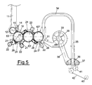
- Figure 5 illustrates an embodiment of the device according to the present invention with three opening cylinders 63, 63' and 63" .
- the cylinders 63, 63', 63" also counter-rotate and rotate a progressively greater speeds, so that the following cylinder strips the preceding cylinder of its film of fibres, sending it forwards.
- the discharging scheme of the fibres into the duct 31 with contracted vein remains the same as the one of figure 2 .
- the cylinder 13, 113 is actuated at a peripheral speed within the range from 5 to 18 m/sec.
- the speed range referring to the last cylinders of the series, 53' and 63" respectively goes from 25 to 50 m/sec, whereas the actuation speed values of the preceding cylinders are less by about 25-40%, for every passage, in order to allow the correct transfer of the film of treated fibres.
- the clothings of the cylinders have a progressively denser and less in relief population of tips, needles or saw-teeth, taking into account that the film deposited on it is progressively cleaner, more stretched out and thinner.
- the devices according to the invention work on the film of fibres with a work scheme that seems similar, but with the difference of serving a single carding machine, i.e. with much lower thicknesses of the layer of flock fibres.
- the ease of detachment and elimination of impurities be they dirt, neps or short fibres, is enormously greater and less aggressive clothings can be adopted, which therefore reduce the deterioration of the fibres.
- the device according to the invention boasts clothings and carding members of size and aggressiveness that differ from those used in conventional openers and carries out an opening and preparation process of the flocks that is more delicate and effective.
- the peripheral speeds on the first cylinder are in the order of 5-15 m/sec.
- the sizes of the cylinders are within the range of 200-300 mm.
- the clothings of the cylinders consist of a population within the range of 4-50 tips per square inch, i.e. 62-765 tips per dm 2 , with needles and/or saw-teeth.
- the device for preparing and feeding flock fibres for a carding machine allows substantial advantages with respect to the prior art. Amongst them, the following characteristics deserve at least an explicit mention.
- the opening cylinders that equip the device practically do not have the peripheral speed limitations that the licker-in rolls on board the carding machines do on the other hand have, being able to work at the peripheral speeds of the openers but on much thinner layers of fibre.
- the carding machine downstream requires a single licker-in, works on a much cleaner feed and can have a higher unitary production.
- the technological advantages deriving from this are substantial, because the opening cylinders on board the device work at the same unitary production of the carding machine and can be set at the ideal speed for discarding dirt, with low production of neps and safeguarding the length of the fibres. In such conditions a good separation of the so-called "pepper trash", the finest fraction of dust, is also obtained, which conventional openers arranged upstream are unable to carry out, working on thicker layers of fibres.
- the wadding mattress presented to the carding machine is of excellent quality, in terms of its smaller and more homogeneous flocks and its greater consistency due to the compression of the air produced in the ventilator integrated in the device, the blower 33. The quality of the band produced by the carding machine, the carding effect and the lifetime of the clothings are substantially advanced due to this.
- the device for preparing and feeding flock fibre to the carding machine according to the present invention allows the conventional scheme shown in figure 1 to be overcome, being able to eliminate from this scheme the conventional opener 5 with large capacity arranged upstream of the carding machines 8 with the described drawbacks, and delegate its function to the opening cylinders of the device according to the invention.
- the functions of the opening devices 5 and feeding silo 7, according to the conventional scheme of figure 1 are fulfilled, overcoming the aforementioned drawbacks thereof and taking the opening and cleaning function of the fibres at the feeding of each carding machine.
- the overall processing scheme allows greater flexibility over the entire battery line and advantages in carrying out the opening of the fibres, since it is carried out on many machines and on a smaller unitary amount, with much thinner layers of fibre, thus giving a more efficient and softer opening on the fibres and giving the carding machine a cleaner and more stretched out material.
- the positive effect also propagates downstream, being able to work on the carding machine with greater unitary capacity, and the carding machine not requiring the series of many licker-in rolls. Such advantages also affect the subsequent ironing, combing, sliver - yarn formation processes.
Landscapes
- Engineering & Computer Science (AREA)
- Textile Engineering (AREA)
- Preliminary Treatment Of Fibers (AREA)
Abstract
Combined device for opening and feeding flock fibres to a single carding machine, comprising a vertical silo that feeds the flock fibres to one or more clothed cylinders to open and clean the flocks, said cylinders being equipped with groups of treatment elements consisting of separating knives, sucking mouths and fixed carding sectors that purify and open the fibrous material, then taking it to a second silo that feeds it in the form of a mattress to the carding machine.

Description
- The present invention refers to the feeding line of carding machines by which the fibrous material coming from bales of raw fibres - for example cotton - is processed in a series of devices, currently known as battery line, until the flock fibres are produced that are fed in the form of a wadding mattress for carding in the carding machines.
- Generally, carding consists of passing the flock material onto a series of equipped surfaces, in other words equipped with a multitude of spikes, rotating at increasing peripheral speed. On these surfaces the fibrous material is opened in the form of single stretched out fibre, the dirt, like dust, short fibres and stubble are to a large extent eliminated, the fibres undergo mixing together and a band of non-twisted fibres is formed, to be sent to the subsequent processing stages.
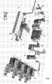
- In order to illustrate the technical problems connected to feeding the carding machines from raw fibres, a scheme of the battery line up to the carding machines is described hereafter with reference to
figure 1 . - In its most general lines, the feeding operation to the cotton-type carding from bales of raw fibre involves the following apparatuses and processes.
- It all starts from bales of cotton that are stretched out side-by-side on the floor to form a fibrous layer and are subjected to the action of a
plucker 1 with one or more reels that crosses with back-and-forth motion the layer of bales that is progressively used up. Such aplucker 1 essentially has the task of opening, i.e. of picking up the flock fibres, the bales of cotton and it is not equipped with dirt elimination elements: all of the material of the bales is therefore taken up and entered into the line. - The
duct 2 carries the flock material by pneumatic transportation to the subsequent treatment. Along its path elements for separating the flow are inserted, for example slits with grids, which allow the heaviest parts of the material carried by the transportation air that travel in the bottom parts of the duct to be eliminated. The first opening point of the opened material consists of anopener 3 with one or two reels, where the first elimination takes place through separation grids that allow the coarsest impurities to be discarded. The reels of this opener are equipped with a small number of pins and not with just real clothings. There are no knives or sucking mouths. In theopener 3 the degree of opening of the flock is low and carries out a sort of pre-opening of the material that is then stored in themixer 4, in which the different quality of the product loaded in the line by theplucker 1 is homogenised. Indeed, it must be taken into account that the bales are not all the same and that the compactness of the fibres inside the individual bales is subject to substantial variation. The flock fibres are therefore fed in pneumatic transportation to theopener 5 itself. - The
opener 5 is equipped with many reels - generally three or four - equipped with a clothing, having saw-teeth, points or needles according to the material to be treated. In general the population of the clothing increases from the first to the last reel, cooperating with impurity elimination groups consisting of knives and sucking mouths. Theopener 5 is the point of the battery line where most of the opening process of the flock material and the elimination of its impurities is carried out. However, this is also the point where there is the most deterioration of the treated fibres, also due to the need to work on large amounts of material - from 600 even up to 1200 kg/h - sufficient to feed around ten carding machines, according to the type of production intended to be carried out. - After the
opener 5 the treated material arrives at thelaunch cage 6 from which it is fed towards thefeeding silo 7 of thecarding machines 8. Said feeding silo, like for example the silo according to patentEP 1.004.693 to the same Applicant, essentially have the task of preparing and feeding, in input to the feeding table of the carding machine, a wadding mattress that is homogeneous in terms of compactness and thickness. From such a table the feeding cylinder loads the cotton onto the introduction and preparation cylinders of the carding machine, known as licker-in, which shall be discussed later on. The operation carried out in thefeeding silo 7 consists of flaking and subsequently compacting the flock material. Flaking is carried out with two or more rotary elements, whereas compacting is carried out with flows of air in the loading area to the carding machine. The thickness of the mattress thus formed is adjusted with levelling cylinders. - The feeding system of the prior art described up to now has some problems. According to a tendency to rationalise and simplify the battery lines, as already outlined above, the size and unitary capacity of the openers have been increased so as to serve a greater number of carding machines downstream. In fact, openers have a much higher unitary productivity than carding machines.
- On such openers the opening points and modes have been intensified, working on greater layer thicknesses. Consequently, in the fibres thus treated the number of neps, in other words the tangles of fibres that are formed during work, increases, the length of the fibres is reduced due to the greater stress undergone, the elimination of dirt occurs to a lower percentage, in other words there is more residual dirt in the flock cotton material fed to the carding machines. The quality of the flock fibres that arrive at the carding machines is substantially worse than conventional battery lines.
- It should be considered that the limiting factor of the productivity of carding machines is the degree of stretching out and of cleaning of the band of fibres that is produced: the greater is the amount of dirt in the starting product, the lower is the production of the carding machine. In order to avoid this situation, according to the most recent technique, an initial preparation stage is foreseen on the carding machines, carried out - instead of on a single cylinder - on a plurality of cleaning and preparation cylinders, commonly known as licker-in, arranged in series in front of the main carding drum. The licker-in rolls in series are equipped with toothed clothings, fixed carding elements, separating knives and sucking mouths to stretch out the fibres and separate the dirt from them. The licker-in rolls in series work at increasing peripheral speed, in any case necessarily less than that of the main carding drum that must "strip" the last licker-in of the fibres carried by its clothing.
- As already stated, the intended purpose of such licker-in rolls is to preventively improve the opening, stretching out and homogeneity of the material arriving on the main carding drum beforehand, and also to separate a further amount of impurities. The expectations for such insertion of the licker-in rolls in series are aimed, overall, at increasing the unitary production capacity of the carding machine, at increasing the quality of the band, at improving the carding effect, i.e. the stretching out of the fibres, increasing the lifetime of the clothings - in particular of the main drum and of its flats - and finally at having a band that is more suited to being used in open-end spinning machines, in which the residual "neps" and stubble can cause frequent breaking of the thread coming out from the spinning rotor.
- Such expectations are only partially respected in carding machines equipped with many licker-in rolls because the amount of dirt that is removed from the fibres is not greatly increased compared to carding machines with a single licker-in. This circumstance, at least to a large extent, can be put down to the fact that the two-three licker-in rolls, which work in series and at increasing speed, have limits to their peripheral speed that must in any case be less than that of the main carding drum, and that is insufficient to obtain the desired purifying effect and is in any case less that what can be achieved in the preceding openers.
- The present invention refers more specifically to a device for preparing and feeding flock fibres to a carding machine that allows higher production and better quality to the carding machine downstream, since it supplies staples that are more open and cleaner, and with the degree of preparation that is most advantageous for the single carding machine that is downstream from it.
- The device according to the invention is defined, in its essential characteristics, in the first claim, and in its preferred embodiments in the claims dependent upon it.
- In order to illustrate the characteristics and advantages of the present invention more clearly, it is described with reference to a typical embodiment thereof shown in
figures 1 to 4 , as a non-limiting example, which schematically illustrate: - in
figure 1 the state of the art and the technical problem of feeding the carding machine in general; - in
figures 2, 2bis ,3 and3bis two schematic embodiments of the present invention with one opening cylinder; - in
figure 4 a schematic embodiment of the present invention with two opening cylinders; - in
figure 5 a schematic embodiment of the present invention with three opening cylinders. - The embodiment illustrated in
figure 2 shows a preparing and feeding device consisting of avertical silo 11 in which the fibrous material comes by pneumatic transportation in air current from thelaunch cage 6 and accumulates in its end part, for example with a fill level control technique already described in the quoted patentEP 1.004.693 . - At the bottom of the
silo 11 the feeding cylinder orroller 12 is arranged that feeds the flock fibres to the equippedcylinder 13 that unravels the material and opens and cleans the flocks picked up. The twocylinders - The
feeding roller 12 is actuated at variable rotation speed and is made lobed or equipped with a clothing with saw-teeth, in a per se known way. Thefeeding roller 12 works facing thewall 14 of the end part of thesilo 11, to create agap 15 for the passage of the fibres between them. - The
cylinder 13 is equipped with groups of flock fibre treatment elements, according to a known scheme for cotton-type openers, for example from patentEP 952.244 figure 2bis . Such a group consists of aclothing 20 with needles or saw-teeth, which receives the fibres from theroller 12, arranges them on the clothing and presents them to the treatment elements that consist of: - separating
knives 21, arranged in the free space around therotary clothing 20, to free the fibrous material from impurities, - sucking
mouths 22 that evacuate the dirt separated by theknives 21, - fixed
carding sectors 23 equipped with tips that, in counterposition to therotary clothing 20, stretch out and open the flock fibres, -
mobile deflectors 24 to modify the opening of the free space between theclothing 20 and the treatment group. - The groups are mounted on rod supports 26.
Elements 28 for containing thecylinder 13 are also foreseen. - At the end of the path through the treatment groups the flock material, opened and cleaner, is detached by a
stripping knife 30 that operates in the ascending contracted vein space that comes into theduct 31 through the effect of theblower 33. - The air-flow goes upstream the
duct 34 and goes downstream thesecond silo 35, along with the flock material. Said silos are preferably formed of quadrangular sections of plates. At the bottom of thesilo 35 are arranged, on one or more of its walls,grids 36 for evacuation from the silo towards the outside and of recycle of the transportation air, which leave the fibrous flock material inside the bottom of the silo. The transportation air is gathered intocollectors 37 and sent back through theduct 38 to theinlet 39 of suction of theblower 33. - In the bottom of the
second silo 35 the density of the flock material can be controlled and regulated by pneumatic effect. A group of discharge cylinders orlobed rollers 41, rotating at commanded speed to regulate the flow rate of fibres, discharges the fibres onto achute 42 that feeds the fibres in the form of a mattress to the carding machine with a conveyingroller 43. - The scheme according to
figure 2 allows fibres even with a large amount of impurities to be processed, whilst still working with a single pair ofcylinders - In the case in which the fibres to be treated do not contain large amounts of impurities, the scheme of
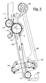
figure 2 can be further simplified, as shown infigures 3 and3bis . - In the embodiment illustrated in
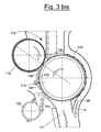
figure 3 , the fibres go down from avertical silo 111 in which the fibrous material comes by pneumatic transportation in air current from thelaunch cage 6. The descending fibres encounter afirst feeding roller 112 that feeds and cooperates with the equippedcylinder 113 to unravel the fibres and clean the flocks picked up. Also in the embodiment offigure 3 the twocylinders roller 112 works facing thewall 114 of the end part of thesilo 111, to create a hingedgap 115 between them that can be regulated for the downward passage of the fibres. On its periphery, similarly to the scheme offigure 2 , thecylinder 113 is equipped with one or more groups of elements for treating the flock fibres, shown in the enlarged detail offigure 3bis , in which a single group of elements is shown as an example. Such a group consists of aclothing 120 with saw-teeth, which receives the fibres from theroller 112, arranges them on its periphery and takes them into contact with: - separating
knives 121, arranged in the free space around therotary clothing 120, to free the fibrous material from impurities, - sucking
mouths 122 that evacuate the dirt separated by theknives 121, -
mobile deflectors 124 to modify the opening of the free space between theclothing 120 and the treatment group. - At the end of the path through the treatment group the flock material, opened and cleaned, carried by the
clothing 120 arrives at themouth 131 into the descendingdischarge channel 135, which also acts as a silo for the unravelled material. In themouth 131 the stripping effect of the fibres from theclothing 120 is obtained both by pneumatic effect with the jet of air, shown with the arrow A, which comes from theblower 133, which crosses theduct 130 and that expands in themouth 131 with Venturi effect, which acts as stripping means drawing air and fibres from theclothing 120, and by centrifugal effect. Such a centrifugal stripping effect can be increased by increasing the rotation speed of thecylinder 113. - The flow of flock material detached from the
clothing 120 is deviated and made to fall with the left face of thewedge 125, which joins themouth 131 with theduct 130. - The current of air A with the flock material descends and is contained in the
silo duct 135. At the end of the descent in theduct 135grids 136 are arranged that separate the transportation air and leave the flock material inside. The transportation air A is taken back with themanifolds 137 and sent on with theduct 138 to theblower 133. - At the bottom of the
silo duct 135 one ormore discharge cylinders 141, actuated to regulate the flow rate of fibres, discharges the fibres onto achute 142 that feeds the fibres in the form of a mattress to the following carding machine with a conveyingroller 143. -
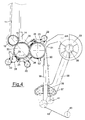
Figure 4 illustrates an embodiment of the device according to the present invention with two openingcylinders 53 and 53'. Compared to the embodiment offigures 2 and 2bis with asingle opening cylinder 13, the same elements keep the same reference numerals. Thecylinders 53, 53' also counter-rotate and rotate a progressively greater speeds, so that the following cylinder strips the preceding cylinder of its film of fibres, sending it forwards. Unlike the previous case according tofigures 2 and 2bis , the fibrous flock material, detached by the strippingknife 30, is always conveyed into theduct 31 and into thesilo 35 with the help of a contracted vein of transportation air coming from theblower 33, but with descending flow. - In the passage between the
cylinders 53, 53' the film of fibres is reversed, since the fibres in a film that are farthest outside on thecylinder 53, and are most exposed to the action of the opening and purifying elements, in the passage to the next cylinder 53' are farthest inside, and this time leave the fibres that had been less opened and less cleaned on theprevious cylinder 53 to the action of said opening and purifying elements. -
Figure 5 illustrates an embodiment of the device according to the present invention with three openingcylinders figures 2 and 2bis with asingle opening cylinder 13, the same elements keep the same reference numerals. Thecylinders duct 31 with contracted vein remains the same as the one offigure 2 . - In the case of the embodiment of the device according to
figures 2 and3 , with a single opening cylinder, thecylinder - On the other hand, in the case of the embodiments with two or three opening cylinders, the speed range referring to the last cylinders of the series, 53' and 63" respectively, goes from 25 to 50 m/sec, whereas the actuation speed values of the preceding cylinders are less by about 25-40%, for every passage, in order to allow the correct transfer of the film of treated fibres.
- In the schemes with many opening cylinders in series the clothings of the cylinders have a progressively denser and less in relief population of tips, needles or saw-teeth, taking into account that the film deposited on it is progressively cleaner, more stretched out and thinner.
- Compared to the
conventional opener 5 offigure 1 , the devices according to the invention work on the film of fibres with a work scheme that seems similar, but with the difference of serving a single carding machine, i.e. with much lower thicknesses of the layer of flock fibres. In the device according to the invention, the ease of detachment and elimination of impurities, be they dirt, neps or short fibres, is enormously greater and less aggressive clothings can be adopted, which therefore reduce the deterioration of the fibres. - Due to the fact that it serves a single carding machine, the device according to the invention boasts clothings and carding members of size and aggressiveness that differ from those used in conventional openers and carries out an opening and preparation process of the flocks that is more delicate and effective.
- Generally, the following parameters are adopted for the solution with many opening cylinders. The peripheral speeds on the first cylinder are in the order of 5-15 m/sec. The sizes of the cylinders are within the range of 200-300 mm. The clothings of the cylinders consist of a population within the range of 4-50 tips per square inch, i.e. 62-765 tips per dm2, with needles and/or saw-teeth.
- The device for preparing and feeding flock fibres for a carding machine according to the present invention allows substantial advantages with respect to the prior art. Amongst them, the following characteristics deserve at least an explicit mention. For the purposes of the quality of the product and the efficiency of the treatment it is quite important that the opening cylinders that equip the device practically do not have the peripheral speed limitations that the licker-in rolls on board the carding machines do on the other hand have, being able to work at the peripheral speeds of the openers but on much thinner layers of fibre. The carding machine downstream requires a single licker-in, works on a much cleaner feed and can have a higher unitary production. The technological advantages deriving from this are substantial, because the opening cylinders on board the device work at the same unitary production of the carding machine and can be set at the ideal speed for discarding dirt, with low production of neps and safeguarding the length of the fibres. In such conditions a good separation of the so-called "pepper trash", the finest fraction of dust, is also obtained, which conventional openers arranged upstream are unable to carry out, working on thicker layers of fibres. The wadding mattress presented to the carding machine is of excellent quality, in terms of its smaller and more homogeneous flocks and its greater consistency due to the compression of the air produced in the ventilator integrated in the device, the
blower 33. The quality of the band produced by the carding machine, the carding effect and the lifetime of the clothings are substantially advanced due to this. - In addition to this, the device for preparing and feeding flock fibre to the carding machine according to the present invention allows the conventional scheme shown in
figure 1 to be overcome, being able to eliminate from this scheme theconventional opener 5 with large capacity arranged upstream of thecarding machines 8 with the described drawbacks, and delegate its function to the opening cylinders of the device according to the invention. - With the device according to the present invention the functions of the
opening devices 5 and feedingsilo 7, according to the conventional scheme offigure 1 , are fulfilled, overcoming the aforementioned drawbacks thereof and taking the opening and cleaning function of the fibres at the feeding of each carding machine. The overall processing scheme allows greater flexibility over the entire battery line and advantages in carrying out the opening of the fibres, since it is carried out on many machines and on a smaller unitary amount, with much thinner layers of fibre, thus giving a more efficient and softer opening on the fibres and giving the carding machine a cleaner and more stretched out material. The positive effect also propagates downstream, being able to work on the carding machine with greater unitary capacity, and the carding machine not requiring the series of many licker-in rolls. Such advantages also affect the subsequent ironing, combing, sliver - yarn formation processes.
Claims (10)
- Combined device for opening and feeding flock fibres to a single carding machine, comprising a vertical silo (11, 111) in which the flock material accumulates in its bottom end part, carrying a feeding cylinder (12, 112) at the base that feeds the flock fibres to one or more cylinders in sequence (13; 53, 53'; 63, 63', 63"; 113) to open and clean the flocks, said cylinders (12, 112) and (13; 53; 63; 113) operating with rotation in unison, characterised in that said cylinders (13; 53, 53'; 63, 63', 63"; 113) are equipped with a clothing (20, 120) that opens and purifies the flock fibres in cooperation with groups of treatment elements consisting of separating knives (21, 121), sucking mouths (22, 122) and fixed carding sectors (23) in counterposition to the rotary clothing (20, 120); and in that, at the end of the path through the treatment groups the flock material, opened and cleaner, is detached by stripping means (30, A) that carry the fibrous material to the base of a second silo (35, 135), from which the fibres are discharged to directly feed the fibres in the form of a mattress to the carding machine.
- Device according to claim 1, comprising a vertical silo (111) in which the flock material accumulates in its bottom end part, carrying a feeding cylinder (112) at the base that feeds the flock fibres to a cylinder (113) to open and clean the flocks, said cylinders (112, 113) and operating with rotation in unison, characterised in that the cylinder (113) is equipped with a clothing (120) that opens and purifies the flock fibres in cooperation with groups of treatment elements consisting of separating knives (121), sucking mouths (122) in counterposition to the rotary clothing (120); and in that, at the end of the path through the treatment groups the flock material is stripped from the clothing through the cooperation of centrifugal effect and Venturi effect generated by a jet of air (A) that expands drawing air and fibres from the clothing (120), and is sent to directly feed the fibres to the carding machine.
- Device according to claim 1, comprising a vertical silo (11) in which the fibrous flock material accumulates in its bottom end part, carrying a feeding cylinder (12) at the base that feeds the flock fibres to one or more cylinders in sequence (13; 53, 53'; 63, 63', 63") to open and clean the flocks, said cylinders (12) and (13; 53; 63) operating with rotation in unison, characterised in that said cylinders (13; 53, 53'; 63, 63', 63") are equipped with a clothing (20) that opens and purifies the flock fibres in cooperation with groups of treatment elements consisting of separating knives (21), sucking mouths (22) and fixed carding sectors (23) in counterposition to the rotary clothing (20); and in that, at the end of the path through the treatment groups the flock material is detached by a stripping knife (30) that operates in cooperation with a flow of air in contracted vein that carries the fibrous material to the base of a second silo (35), from which the fibres are discharged to directly feed the fibres to the carding machine.
- Device according to claim 3, characterised in that it comprises a plurality of clothed cylinders (53, 53'; 63, 63', 63") in sequence to open and clean the flocks, which counter-rotate and that rotate at progressively higher speed, so that the following cylinder strips the preceding cylinder of its film of fibres.
- Device according to claim 3, characterised in that the groups of treatment elements of the flock fibres comprise, at the outlet of the group, mobile deflectors (24, 124) to modify the opening of the free space between the clothing (20, 120) and the treatment group.
- Device according to claim 4, characterised in that the clothings of the cylinders (53, 53'; 63, 63', 63") in sequence to open and clean the flocks have a progressively denser and less in relief population of tips, needles or saw-teeth.
- Device according to claim 1 or 2, characterised in that it comprises a single opening cylinder (13, 113) actuated at a peripheral speed within the range from 5 to 18 m/sec.
- Device according to claim 4, characterised in that it comprises two or three opening cylinders, in which the last cylinders of the series are actuated at a peripheral speed within the range from 25 to 50 m/sec, the actuation speed values of the preceding cylinders are lower by within the range of 25-40% for each passage.
- Device according to claim 4, characterised in that it comprises many opening cylinders, in which the first cylinder is actuated at a peripheral speed in the order of 5-15 m/sec, the size of the cylinders being within the range of 200-300 mm.
- Device according to claim 3, characterised in that the clothings of the cylinders consists of a population within the range of 62-765 tips per dm2, said clothings being with needles and/or saw-teeth.
Priority Applications (1)
| Application Number | Priority Date | Filing Date | Title |
|---|---|---|---|
| EP07111856A EP2011908A1 (en) | 2007-07-05 | 2007-07-05 | Combined device for opening and feeding flock fibres to a carding machine |
Applications Claiming Priority (1)
| Application Number | Priority Date | Filing Date | Title |
|---|---|---|---|
| EP07111856A EP2011908A1 (en) | 2007-07-05 | 2007-07-05 | Combined device for opening and feeding flock fibres to a carding machine |
Publications (1)
| Publication Number | Publication Date |
|---|---|
| EP2011908A1 true EP2011908A1 (en) | 2009-01-07 |
Family
ID=38625845
Family Applications (1)
| Application Number | Title | Priority Date | Filing Date |
|---|---|---|---|
| EP07111856A Withdrawn EP2011908A1 (en) | 2007-07-05 | 2007-07-05 | Combined device for opening and feeding flock fibres to a carding machine |
Country Status (1)
| Country | Link |
|---|---|
| EP (1) | EP2011908A1 (en) |
Cited By (7)
| Publication number | Priority date | Publication date | Assignee | Title |
|---|---|---|---|---|
| CN103225136A (en) * | 2013-05-15 | 2013-07-31 | 海门市麒新纺织机械有限公司 | Opening machine |
| CN107904716A (en) * | 2017-12-23 | 2018-04-13 | 盐城工业职业技术学院 | A kind of poly- suede spinning equipment of super short-thin soft fiber |
| EP3530781A1 (en) * | 2018-02-26 | 2019-08-28 | Maschinenfabrik Rieter AG | Feeding device of a carding machine |
| CN114263008A (en) * | 2021-12-31 | 2022-04-01 | 浙江通圆经编股份有限公司 | Cloth removes floats hair device |
| WO2022135977A1 (en) * | 2020-12-22 | 2022-06-30 | Trützschler Group SE | Method for operating a device on or in a textile machine, and textile machine operated therewith |
| EP4155440A1 (en) * | 2021-09-28 | 2023-03-29 | Maschinenfabrik Rieter AG | Fibre material entry for a cleaning machine |
| WO2025160688A1 (en) * | 2024-01-29 | 2025-08-07 | 里特机械公司 | Impurity delivery system for carding machine, carding machine thereof, and method for modifying carding machine |
Citations (6)
| Publication number | Priority date | Publication date | Assignee | Title |
|---|---|---|---|---|
| US4858278A (en) * | 1987-04-07 | 1989-08-22 | Hergeth Hollingsworth Gmbh | Apparatus for cleaning and opening textile fiber material |
| US5146652A (en) * | 1990-01-23 | 1992-09-15 | Trutzschler Gmbh & Co. Kg | Apparatus for opening and cleaning fiber material |
| EP1004693A2 (en) * | 1998-11-24 | 2000-05-31 | Marzoli S.p.A. | Device for preparation and opening of flock fibres to be supplied to a carder |
| US6185787B1 (en) * | 1997-07-30 | 2001-02-13 | Maschinenfabrik Rieter Ag | Fiber flock cleaner |
| EP1262580A1 (en) * | 2001-05-31 | 2002-12-04 | MARZOLI S.p.A. | Opening machine and opening method for fibre material |
| WO2007048262A2 (en) * | 2005-10-28 | 2007-05-03 | Maschinenfabrik Rieter Ag | Opening roller and chute feed for a carding machine |
-
2007
- 2007-07-05 EP EP07111856A patent/EP2011908A1/en not_active Withdrawn
Patent Citations (6)
| Publication number | Priority date | Publication date | Assignee | Title |
|---|---|---|---|---|
| US4858278A (en) * | 1987-04-07 | 1989-08-22 | Hergeth Hollingsworth Gmbh | Apparatus for cleaning and opening textile fiber material |
| US5146652A (en) * | 1990-01-23 | 1992-09-15 | Trutzschler Gmbh & Co. Kg | Apparatus for opening and cleaning fiber material |
| US6185787B1 (en) * | 1997-07-30 | 2001-02-13 | Maschinenfabrik Rieter Ag | Fiber flock cleaner |
| EP1004693A2 (en) * | 1998-11-24 | 2000-05-31 | Marzoli S.p.A. | Device for preparation and opening of flock fibres to be supplied to a carder |
| EP1262580A1 (en) * | 2001-05-31 | 2002-12-04 | MARZOLI S.p.A. | Opening machine and opening method for fibre material |
| WO2007048262A2 (en) * | 2005-10-28 | 2007-05-03 | Maschinenfabrik Rieter Ag | Opening roller and chute feed for a carding machine |
Cited By (11)
| Publication number | Priority date | Publication date | Assignee | Title |
|---|---|---|---|---|
| CN103225136A (en) * | 2013-05-15 | 2013-07-31 | 海门市麒新纺织机械有限公司 | Opening machine |
| CN107904716A (en) * | 2017-12-23 | 2018-04-13 | 盐城工业职业技术学院 | A kind of poly- suede spinning equipment of super short-thin soft fiber |
| EP3530781A1 (en) * | 2018-02-26 | 2019-08-28 | Maschinenfabrik Rieter AG | Feeding device of a carding machine |
| CH714679A1 (en) * | 2018-02-26 | 2019-08-30 | Rieter Ag Maschf | Hopper discharge for feeding a card. |
| CN110195273A (en) * | 2018-02-26 | 2019-09-03 | 里特机械公司 | Equipment is fed for for carding machine |
| CN110195273B (en) * | 2018-02-26 | 2022-11-29 | 里特机械公司 | Feeding equipment for cards |
| WO2022135977A1 (en) * | 2020-12-22 | 2022-06-30 | Trützschler Group SE | Method for operating a device on or in a textile machine, and textile machine operated therewith |
| CN116438337A (en) * | 2020-12-22 | 2023-07-14 | 特吕茨施勒集团欧洲公司 | Method for operating a device on or in a spinning machine and spinning machine operated thereby |
| EP4155440A1 (en) * | 2021-09-28 | 2023-03-29 | Maschinenfabrik Rieter AG | Fibre material entry for a cleaning machine |
| CN114263008A (en) * | 2021-12-31 | 2022-04-01 | 浙江通圆经编股份有限公司 | Cloth removes floats hair device |
| WO2025160688A1 (en) * | 2024-01-29 | 2025-08-07 | 里特机械公司 | Impurity delivery system for carding machine, carding machine thereof, and method for modifying carding machine |
Similar Documents
| Publication | Publication Date | Title |
|---|---|---|
| EP2011908A1 (en) | Combined device for opening and feeding flock fibres to a carding machine | |
| US6212738B1 (en) | Method and device for fibre production | |
| JPH0213048B2 (en) | ||
| EP1262580A1 (en) | Opening machine and opening method for fibre material | |
| US4345356A (en) | Mechanism for eliminating impurities from fibrous material, in particular cotton | |
| GB2134553A (en) | Carding apparatus | |
| CN109913983A (en) | A kind of pure cotton combed woven yarn high-efficiency method for producing | |
| US4040948A (en) | Device for cleaning flock formed by natural fibers, especially cotton flock, of dirt particles | |
| US5737806A (en) | Apparatus for treating fiber and producing a fiber lap therefrom | |
| CN116043371A (en) | Anti-winding cashmere spinning device with opening function | |
| CN110004548A (en) | Production method of knitted blended yarn | |
| CN109023602A (en) | A kind of area Zhu Fenshu sealing high yield carding machine suitable for non-woven cloth spun lacing production line | |
| US8112845B2 (en) | Method and apparatus for separating foreign matter from fibrous material | |
| US6061875A (en) | Powered roll gin stand | |
| CN101348954A (en) | Aggregate unit for bundle fiber and feeding bundle fiber into carding machine | |
| GB2367306A (en) | Separating blade system for spinning preparation machine | |
| EP0927779B1 (en) | Feeding device for fiber mats in flat carders | |
| CN207525395U (en) | Carding machine | |
| CN110621818B (en) | Carding machine | |
| US1165088A (en) | Carding-machine. | |
| CN117966322A (en) | A production process for vortex spinning ultra-high count yarn | |
| CN110894626B (en) | Cotton sliver stretch breaking machine for yarn production | |
| CN211771702U (en) | Cotton opening device for cotton yarn production | |
| US1751306A (en) | Cotton gin | |
| US3080617A (en) | Fiber proportioning, blending and preparation method, system and apparatus |
Legal Events
| Date | Code | Title | Description |
|---|---|---|---|
| PUAI | Public reference made under article 153(3) epc to a published international application that has entered the european phase |
Free format text: ORIGINAL CODE: 0009012 |
|
| AK | Designated contracting states |
Kind code of ref document: A1 Designated state(s): AT BE BG CH CY CZ DE DK EE ES FI FR GB GR HU IE IS IT LI LT LU LV MC MT NL PL PT RO SE SI SK TR |
|
| AX | Request for extension of the european patent |
Extension state: AL BA HR MK RS |
|
| AKX | Designation fees paid | ||
| REG | Reference to a national code |
Ref country code: DE Ref legal event code: 8566 |
|
| STAA | Information on the status of an ep patent application or granted ep patent |
Free format text: STATUS: THE APPLICATION IS DEEMED TO BE WITHDRAWN |
|
| 18D | Application deemed to be withdrawn |
Effective date: 20090708 |