EP2011753B1 - Falztisch und entsprechende Falzvorrichtung - Google Patents
Falztisch und entsprechende Falzvorrichtung Download PDFInfo
- Publication number
- EP2011753B1 EP2011753B1 EP08159620A EP08159620A EP2011753B1 EP 2011753 B1 EP2011753 B1 EP 2011753B1 EP 08159620 A EP08159620 A EP 08159620A EP 08159620 A EP08159620 A EP 08159620A EP 2011753 B1 EP2011753 B1 EP 2011753B1
- Authority
- EP
- European Patent Office
- Prior art keywords
- folding
- height
- guiding
- routing
- base body
- Prior art date
- Legal status (The legal status is an assumption and is not a legal conclusion. Google has not performed a legal analysis and makes no representation as to the accuracy of the status listed.)
- Not-in-force
Links
Images

Classifications
-
- B—PERFORMING OPERATIONS; TRANSPORTING
- B65—CONVEYING; PACKING; STORING; HANDLING THIN OR FILAMENTARY MATERIAL
- B65H—HANDLING THIN OR FILAMENTARY MATERIAL, e.g. SHEETS, WEBS, CABLES
- B65H5/00—Feeding articles separated from piles; Feeding articles to machines
- B65H5/02—Feeding articles separated from piles; Feeding articles to machines by belts or chains, e.g. between belts or chains
- B65H5/021—Feeding articles separated from piles; Feeding articles to machines by belts or chains, e.g. between belts or chains by belts
- B65H5/026—Feeding articles separated from piles; Feeding articles to machines by belts or chains, e.g. between belts or chains by belts between belts and stationary pressing, supporting or guiding elements forming a transport nip
-
- B—PERFORMING OPERATIONS; TRANSPORTING
- B65—CONVEYING; PACKING; STORING; HANDLING THIN OR FILAMENTARY MATERIAL
- B65H—HANDLING THIN OR FILAMENTARY MATERIAL, e.g. SHEETS, WEBS, CABLES
- B65H29/00—Delivering or advancing articles from machines; Advancing articles to or into piles
- B65H29/12—Delivering or advancing articles from machines; Advancing articles to or into piles by means of the nip between two, or between two sets of, moving tapes or bands or rollers
-
- B—PERFORMING OPERATIONS; TRANSPORTING
- B65—CONVEYING; PACKING; STORING; HANDLING THIN OR FILAMENTARY MATERIAL
- B65H—HANDLING THIN OR FILAMENTARY MATERIAL, e.g. SHEETS, WEBS, CABLES
- B65H45/00—Folding thin material
- B65H45/12—Folding articles or webs with application of pressure to define or form crease lines
- B65H45/18—Oscillating or reciprocating blade folders
Definitions
- the present invention relates to a folding table according to the preamble of claim 1.
- Corner fold devices are known which are adapted to fold a flat product, such as a sheet or a signature which has been printed in an offset rotary press. Such a device is known to US 2005/90932 .
- DE 26 38 784 describes a transfer table.
- These square fold devices include a folding table, folding rolls and a folding blade.
- the folding blade is used to push the flat products through a slot in the table in a gap formed by the rollers.
- the square bend device is provided with flat product conveyor belts for routing on the bending table.
- the conveyor belts are driven by the product to be folded in a direction transverse to their direction of conveyance. As a result, the belts overlap transversely and create jams.
- the object of the invention is to increase the time of availability of a folding device, in particular of a right-angle fold device.
- the object of the invention is a folding table, comprising the features of claim 1.
- the folding table comprises one or more of the features indicated in the dependent claims.
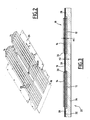
- the square folding device 2 comprises a folding table 4, a folding blade 6, and two folding rollers 8, 10.
- the folding blade 6 is movable back and forth in a folding direction DP and is arranged on one side of the folding table 4.
- the two folding rollers 8, 10 have parallel axes and form a folding interstice between them.
- the square crease device 2 comprises lower conveyor belts 12 and upper conveyor belts 14.
- the conveyor belts 12 and 14 are adapted for conveying flat products to be folded 16, such as signatures or sheets, onto the folding table 4 according to a direction of routing D and in a direction of routing S (see Figure 2 ).
- the conveyor belts 12 and 14 extend parallel to the conveying direction D and are driven in the direction of conveyance S.
- the folding table 4 has a folding face 18 facing the folding blade 6 and a lower face 20 facing the folding rollers 8, 10.
- the folding table 4 defines a folding slot 22 through which the products to be folded 16 are pushed by the blade 6.
- the folding slot 22 extends parallel to the routing direction D.
- the folding table 4 is provided with means 24 for guiding the lower conveyor belts 12 in the conveying direction D. These guide means 24 are adapted to oppose a deflection of the lower conveyor belts 12 towards the slot of the conveyor. folding 22, therefore transversely to the direction D, when the product to be folded 16 is pushed by the folding blade 6 through the folding slot 22.
- the folding table 4 comprises a base body 26 and guide ribs 28 extending in the direction of routing D.
- the base body 26 has a general parallelepiped shape.
- the ribs 28 are arranged on the base body 26 and form the guide means 24.
- the ribs 28 and the base body 26 form the folding face 18.
- Two adjacent guide ribs 28 form between them a guide channel 30 (see FIG. Figure 3 ) in which extends either a lower conveyor belt 12 or several lower conveyor belts 12. Furthermore, the conveying channel 30 closest to the folding slot 22 receives two lower conveyor belts 12.
- the two belts conveying 12 in the same conveying channel, on both sides of the fold blade 6, are used for better guidance and better maintenance during the fold phase, notebooks, signatures, sheets, in particular narrow width (small width paper strip).
- Each guide rib 28 is thus arranged between the associated lower conveyor belt 12 and the folding slot 22 so as to guide the belt 12 during folding.
- the lower conveyor belts 12 have a first height H1, measured perpendicular to the table plane P, and each guide rib 28 has a second height H2, also measured perpendicularly to the plane P of the table.
- the second height H2 is either less or identical or is strictly less than the height H1 so as not to disturb the folding of the product to be folded.
- the guide rib 28 has a height H2 which is between 0, 5 and 0.8 times the first height H1, and thus contributes to supporting the product to bend 16 during the routing.
- the base body 26 and the ribs 28 are provided with an anti-friction coating 32, which is advantageously made of chromium. This coating 32 promotes the sliding of the conveyor belts 12 and the products to be folded on the table 4.
- the second height H2 is measured from the free surface of the coating 32 of the base body 26 to the free surface of the coating 32 of the rib 28.
- the guide ribs 28 are made in one piece and in particular in one piece with the base body 26, which reduces the manufacturing costs of the folding device.
- the base body 26 and the ribs 28 are made for example of steel or aluminum.
- the folding table according to the invention reduces with simple and economical means the risk of jamming of the bending machines and thus increases the reliability of the folder.
- conveyor belts 12, 14 can be replaced by other conveying elements.
Landscapes
- Engineering & Computer Science (AREA)
- Mechanical Engineering (AREA)
- Folding Of Thin Sheet-Like Materials, Special Discharging Devices, And Others (AREA)
Claims (10)
- Falztisch (4), insbesondere für eine Falzmaschine, die mit einer Winkelfalzvorrichtung ausgerüstet ist, des Typs, der umfasst:- eine Falzfläche (18), die angepasst ist, ein flaches, zu faltendes Produkt (16) aufzunehmen,- einen Falzspalt (22), der sich gemäß einer Förderrichtung (D) erstreckt, wobei sich der Tisch gemäß einer Tischebene (P) erstreckt,- wobei die Falzfläche (18) Führungsmittel (24) umfasst, die angepasst sind, um ein Förderelement (12) eines flachen, zu faltenden Produkts (16) gemäß der Förderrichtung (D) zu führen,- wobei der Tisch einen Grundkörper (26) aufweist und die Führungsmittel (24) mindestens ein Führungselement (28) aufweisen, das auf dem Grundkörper angeordnet ist, und der Grundkörper und das oder jedes Führungselement die Falzfläche (18) bilden, dadurch gekennzeichnet, dass das Führungselement (28) aus einem Stück, namentlich aus einem einzigen Teil mit dem Grundkörper (26) hergestellt ist.
- Falztisch nach Anspruch 1, dadurch gekennzeichnet, dass das Führungselement eine Führungsrippe (28) ist.
- Falztisch nach Anspruch 2, dadurch gekennzeichnet, dass der Tisch zwei benachbarte Führungsrippen (28) umfasst, die zwischen sich einen Führungskanal (30) bilden, in dem sich entweder ein unteres Förderband (12) oder mehrere untere Förderbänder (12) erstrecken.
- Falztisch nach Anspruch 3, dadurch gekennzeichnet, dass der am nächsten zum Falzspalt (22) liegende Transportkanal (30) zwei untere Förderbänder (12) umfasst.
- Falztisch nach einem beliebigen der vorhergehenden Ansprüche, dadurch gekennzeichnet, dass die Falzfläche (18) eine Anti-Reibungsbeschichtung (32), insbesondere aus Chrom umfasst.
- Winkelfalzvorrichtung des Typs, der umfasst:- einen Falztisch (4) und- mindestens ein Förderelement (12) für ein flaches, zu faltendes Produkt (16), insbesondere ein Förderband (12),dadurch gekennzeichnet, dass der Falztisch ein Falztisch (4) nach einem beliebigen der vorhergehenden Ansprüche ist und dass das Förderelement (12) durch Führungsmittel (24) geführt ist.
- Winkelfalzvorrichtung nach Anspruch 6, dadurch gekennzeichnet, dass das Förderelement (12) eine erste Höhe (H1) und die Führungsmittel (24) eine zweite Höhe (H2) aufweisen, wobei diese Höhen (H1, H2) senkrecht zur Tischebene gemessen sind und dass die zweite Höhe kleiner als oder gleich der ersten Höhe ist.
- Winkelfalzvorrichtung nach Anspruch 7, dadurch gekennzeichnet, dass die zweite Höhe streng kleiner als die erste Höhe ist und insbesondere die zweite Höhe (H2) zwischen 0,5 und 0,8 der ersten Höhe (H1) liegt.
- Winkelfalzvorrichtung nach Anspruch 8, dadurch gekennzeichnet, dass die Führungsmittel mindestens einen Führungskanal (30) bilden, in dem ein Förderelement (12), insbesondere ein einziges Förderelement, (12) angeordnet ist.
- Winkelfalzvorrichtung nach Anspruch 9, dadurch gekennzeichnet, dass das Führungselement (28) zwischen dem Falzspalt (22) und dem zugeordneten Förderelement (12) angeordnet ist.
Applications Claiming Priority (1)
| Application Number | Priority Date | Filing Date | Title |
|---|---|---|---|
| FR0756245A FR2918360B1 (fr) | 2007-07-03 | 2007-07-03 | Table de pliage et dispositif de pli d'equerre correspondant |
Publications (2)
| Publication Number | Publication Date |
|---|---|
| EP2011753A1 EP2011753A1 (de) | 2009-01-07 |
| EP2011753B1 true EP2011753B1 (de) | 2010-10-13 |
Family
ID=38799349
Family Applications (1)
| Application Number | Title | Priority Date | Filing Date |
|---|---|---|---|
| EP08159620A Not-in-force EP2011753B1 (de) | 2007-07-03 | 2008-07-03 | Falztisch und entsprechende Falzvorrichtung |
Country Status (6)
| Country | Link |
|---|---|
| US (1) | US7988609B2 (de) |
| EP (1) | EP2011753B1 (de) |
| JP (1) | JP2009029627A (de) |
| CN (1) | CN101353122B (de) |
| DE (1) | DE602008002964D1 (de) |
| FR (1) | FR2918360B1 (de) |
Families Citing this family (3)
| Publication number | Priority date | Publication date | Assignee | Title |
|---|---|---|---|---|
| CN105966977A (zh) * | 2016-06-23 | 2016-09-28 | 浙江寿原机械有限公司 | 一种折页机用刀组 |
| CN109591364B (zh) * | 2018-12-11 | 2020-11-27 | 武汉工程大学 | 一种包装纸盒自动上料、折叠成形和视觉检测的装置 |
| CN116573442B (zh) * | 2023-05-23 | 2024-04-05 | 德州春祥包装制品有限公司 | 一种纸板加工自动折叠装置及方法 |
Family Cites Families (12)
| Publication number | Priority date | Publication date | Assignee | Title |
|---|---|---|---|---|
| DE2638784B2 (de) * | 1976-08-27 | 1979-12-20 | Georg Spiess Gmbh, 8906 Gersthofen | Anlegetisch für einen Bogenanleger |
| FR2546818B1 (fr) * | 1983-06-06 | 1987-03-20 | Marinoni Harris Sa | Dispositif pour ralentir les exemplaires dans un pli d'equerre de plieuse utilisee en relation avec les presses rotatives |
| GB8800720D0 (en) * | 1988-01-13 | 1988-02-10 | Xerox Corp | Plural belt document feeder |
| DE4012948A1 (de) * | 1990-04-24 | 1991-10-31 | Roland Man Druckmasch | Vorrichtung zum foerdern von druckbogen |
| WO1995018057A1 (de) * | 1993-12-24 | 1995-07-06 | Koenig Und Bauer-Albert Aktiengesellschaft | Verfahren und vorrichtung zum herstellen eines längsfalzes |
| DE19724957A1 (de) * | 1997-06-12 | 1999-01-21 | Avery Dennison Corp | Flachriemen und Flachriemenvorrichtung, insbesondere für Papierfördereinrichtungen |
| US20050090932A1 (en) * | 2003-10-27 | 2005-04-28 | Heidelberger Druckmaschinen Aktiengesellschaft | Apparatus for processing preliminary products in the graphics industry |
| DE102004023318B4 (de) * | 2004-05-07 | 2008-04-17 | Man Roland Druckmaschinen Ag | Falzeinrichtung für Druckmaschinen oder Falzapparate |
| ITTV20040115A1 (it) * | 2004-10-18 | 2005-01-18 | Plastomeccanica Spa | Guida, particolarmente per nastri trasportatori. |
| DE102005024181B4 (de) * | 2005-05-23 | 2007-08-02 | Von Ardenne Anlagentechnik Gmbh | Transporteinrichtung, insbesondere zur Verwendung in einer Vakuumkammer |
| US7673741B2 (en) * | 2005-08-08 | 2010-03-09 | Inter-Source Recovery Systems | Apparatus and method for conveying materials |
| JP4277288B2 (ja) * | 2006-11-28 | 2009-06-10 | 株式会社東京機械製作所 | 輪転機用チョッパー折り装置 |
-
2007
- 2007-07-03 FR FR0756245A patent/FR2918360B1/fr not_active Expired - Fee Related
-
2008
- 2008-07-02 US US12/217,257 patent/US7988609B2/en not_active Expired - Fee Related
- 2008-07-03 DE DE602008002964T patent/DE602008002964D1/de active Active
- 2008-07-03 CN CN2008102147772A patent/CN101353122B/zh not_active Expired - Fee Related
- 2008-07-03 JP JP2008174622A patent/JP2009029627A/ja active Pending
- 2008-07-03 EP EP08159620A patent/EP2011753B1/de not_active Not-in-force
Also Published As
| Publication number | Publication date |
|---|---|
| CN101353122A (zh) | 2009-01-28 |
| CN101353122B (zh) | 2012-07-25 |
| US7988609B2 (en) | 2011-08-02 |
| DE602008002964D1 (de) | 2010-11-25 |
| FR2918360A1 (fr) | 2009-01-09 |
| EP2011753A1 (de) | 2009-01-07 |
| JP2009029627A (ja) | 2009-02-12 |
| US20090042708A1 (en) | 2009-02-12 |
| FR2918360B1 (fr) | 2010-02-05 |
Similar Documents
| Publication | Publication Date | Title |
|---|---|---|
| US20100096801A1 (en) | Paper sheet ejecting/collecting apparatus | |
| EP2634125B1 (de) | Vorrichtung zum Falten eines Blattstapels | |
| US8434609B2 (en) | Method for aligning flat products on a side edge and conveying device for realizing the method | |
| US7419155B2 (en) | Device for separating sheet-type products | |
| US9334135B2 (en) | Sheet braking device | |
| EP2011753A1 (de) | Falztisch und entsprechende Falzvorrichtung | |
| EP1803673B1 (de) | Falzapparat | |
| EP3740341B1 (de) | Trägervorrichtung mit auf einer basis montierten bändern zur lagerung oder zum transport einzelner blätter oder stapel von verpackungsmaterial ; bandförderanlage | |
| CN111615493A (zh) | 输送带组件 | |
| US20110237416A1 (en) | Sheet post-processing apparatus and image forming apparatus | |
| EP2039639B1 (de) | Falzwalze und Falzapparat | |
| CN1188066A (zh) | 进纸/排纸辊机构 | |
| WO2005005294A3 (de) | Vorrichtung zum selektiven stapelförmigen ablegen von blättern | |
| WO2017130302A1 (ja) | 紙葉類搬送機構及び紙葉類取扱装置 | |
| US6340406B1 (en) | Simple pressure seal units | |
| EP3426449A1 (de) | Ausstosselement und maschine zur verarbeitung von blattförmigen elementen | |
| US20090243208A1 (en) | Auxiliary drive device for the conveying of sheetson a feed table of a cutting press | |
| EP2844460B1 (de) | Modul mit gestell, und damit ausgestattete biege-klebe-presse | |
| CH682999A5 (fr) | Dispositif de taquage pour une station d'introduction de machine de travail, tel que découpage ou impression, d'élements en plaque ou feuilles en vue de la production d'emballages. | |
| EP3523135B1 (de) | Vorrichtung zum falten von blättern | |
| WO2017178437A1 (fr) | Organe de prehension, barre de pinces et machine de traitement d'elements en forme de feuilles | |
| EP1889795B1 (de) | Schutzvorrichtung für Materialien in Spulenform, insbesondere Metallbleche | |
| EP0096603B1 (de) | Anschläge zum Ausrichten von Bogen | |
| EP2791036B1 (de) | Fördervorrichtung für flache gegenstände auf einer kante und postsortiermaschine | |
| JP4800652B2 (ja) | 調節可能な折りナイフを備えたクロス折りモジュールおよび折り機 |
Legal Events
| Date | Code | Title | Description |
|---|---|---|---|
| PUAI | Public reference made under article 153(3) epc to a published international application that has entered the european phase |
Free format text: ORIGINAL CODE: 0009012 |
|
| AK | Designated contracting states |
Kind code of ref document: A1 Designated state(s): AT BE BG CH CY CZ DE DK EE ES FI FR GB GR HR HU IE IS IT LI LT LU LV MC MT NL NO PL PT RO SE SI SK TR |
|
| AX | Request for extension of the european patent |
Extension state: AL BA MK RS |
|
| 17P | Request for examination filed |
Effective date: 20090618 |
|
| 17Q | First examination report despatched |
Effective date: 20090715 |
|
| AKX | Designation fees paid |
Designated state(s): CH DE FR GB IT LI NL |
|
| GRAP | Despatch of communication of intention to grant a patent |
Free format text: ORIGINAL CODE: EPIDOSNIGR1 |
|
| GRAS | Grant fee paid |
Free format text: ORIGINAL CODE: EPIDOSNIGR3 |
|
| GRAA | (expected) grant |
Free format text: ORIGINAL CODE: 0009210 |
|
| AK | Designated contracting states |
Kind code of ref document: B1 Designated state(s): CH DE FR GB IT LI NL |
|
| REG | Reference to a national code |
Ref country code: GB Ref legal event code: FG4D Free format text: NOT ENGLISH |
|
| REG | Reference to a national code |
Ref country code: CH Ref legal event code: EP Ref country code: CH Ref legal event code: NV Representative=s name: KIRKER & CIE S.A. |
|
| REF | Corresponds to: |
Ref document number: 602008002964 Country of ref document: DE Date of ref document: 20101125 Kind code of ref document: P |
|
| REG | Reference to a national code |
Ref country code: NL Ref legal event code: VDEP Effective date: 20101013 |
|
| PG25 | Lapsed in a contracting state [announced via postgrant information from national office to epo] |
Ref country code: NL Free format text: LAPSE BECAUSE OF FAILURE TO SUBMIT A TRANSLATION OF THE DESCRIPTION OR TO PAY THE FEE WITHIN THE PRESCRIBED TIME-LIMIT Effective date: 20101013 |
|
| PLBE | No opposition filed within time limit |
Free format text: ORIGINAL CODE: 0009261 |
|
| STAA | Information on the status of an ep patent application or granted ep patent |
Free format text: STATUS: NO OPPOSITION FILED WITHIN TIME LIMIT |
|
| 26N | No opposition filed |
Effective date: 20110714 |
|
| REG | Reference to a national code |
Ref country code: DE Ref legal event code: R097 Ref document number: 602008002964 Country of ref document: DE Effective date: 20110714 |
|
| PG25 | Lapsed in a contracting state [announced via postgrant information from national office to epo] |
Ref country code: IT Free format text: LAPSE BECAUSE OF FAILURE TO SUBMIT A TRANSLATION OF THE DESCRIPTION OR TO PAY THE FEE WITHIN THE PRESCRIBED TIME-LIMIT Effective date: 20101013 |
|
| PGFP | Annual fee paid to national office [announced via postgrant information from national office to epo] |
Ref country code: DE Payment date: 20120727 Year of fee payment: 5 Ref country code: FR Payment date: 20120731 Year of fee payment: 5 |
|
| REG | Reference to a national code |
Ref country code: CH Ref legal event code: PL |
|
| GBPC | Gb: european patent ceased through non-payment of renewal fee |
Effective date: 20120703 |
|
| PG25 | Lapsed in a contracting state [announced via postgrant information from national office to epo] |
Ref country code: LI Free format text: LAPSE BECAUSE OF NON-PAYMENT OF DUE FEES Effective date: 20120731 Ref country code: GB Free format text: LAPSE BECAUSE OF NON-PAYMENT OF DUE FEES Effective date: 20120703 Ref country code: CH Free format text: LAPSE BECAUSE OF NON-PAYMENT OF DUE FEES Effective date: 20120731 |
|
| REG | Reference to a national code |
Ref country code: DE Ref legal event code: R119 Ref document number: 602008002964 Country of ref document: DE Effective date: 20140201 |
|
| REG | Reference to a national code |
Ref country code: FR Ref legal event code: ST Effective date: 20140331 |
|
| PG25 | Lapsed in a contracting state [announced via postgrant information from national office to epo] |
Ref country code: DE Free format text: LAPSE BECAUSE OF NON-PAYMENT OF DUE FEES Effective date: 20140201 |
|
| PG25 | Lapsed in a contracting state [announced via postgrant information from national office to epo] |
Ref country code: FR Free format text: LAPSE BECAUSE OF NON-PAYMENT OF DUE FEES Effective date: 20130731 |