EP2011702A2 - Support for a vehicle airbag - Google Patents
Support for a vehicle airbag Download PDFInfo
- Publication number
- EP2011702A2 EP2011702A2 EP08010656A EP08010656A EP2011702A2 EP 2011702 A2 EP2011702 A2 EP 2011702A2 EP 08010656 A EP08010656 A EP 08010656A EP 08010656 A EP08010656 A EP 08010656A EP 2011702 A2 EP2011702 A2 EP 2011702A2
- Authority
- EP
- European Patent Office
- Prior art keywords
- support
- strut
- elastic element
- support strut
- airbag housing
- Prior art date
- Legal status (The legal status is an assumption and is not a legal conclusion. Google has not performed a legal analysis and makes no representation as to the accuracy of the status listed.)
- Granted
Links
Images
Classifications
-
- B—PERFORMING OPERATIONS; TRANSPORTING
- B60—VEHICLES IN GENERAL
- B60R—VEHICLES, VEHICLE FITTINGS, OR VEHICLE PARTS, NOT OTHERWISE PROVIDED FOR
- B60R21/00—Arrangements or fittings on vehicles for protecting or preventing injuries to occupants or pedestrians in case of accidents or other traffic risks
- B60R21/02—Occupant safety arrangements or fittings, e.g. crash pads
- B60R21/16—Inflatable occupant restraints or confinements designed to inflate upon impact or impending impact, e.g. air bags
- B60R21/20—Arrangements for storing inflatable members in their non-use or deflated condition; Arrangement or mounting of air bag modules or components
- B60R21/205—Arrangements for storing inflatable members in their non-use or deflated condition; Arrangement or mounting of air bag modules or components in dashboards
- B60R21/206—Arrangements for storing inflatable members in their non-use or deflated condition; Arrangement or mounting of air bag modules or components in dashboards in the lower part of dashboards, e.g. for protecting the knees
Definitions
- a support for a knee airbag housing wherein a tube is fixed at each end in the lower region on an A-pillar and on a center strut of a structural cross member, wherein the center strut is attached to a central tunnel.
- the tube is thus arranged transversely to the vehicle longitudinal direction and can absorb by its connection to the A-pillar and the center strut, the reaction forces during inflation of an airbag and the support forces during an impact of the motor vehicle and forward to the tethered body structure. Since the tube is firmly connected at each end to the A-pillar and with the center strut, when force is applied to the tube (eg by triggering the knee airbag or a knee intrusion), the force is passed through the connecting elements. In this case, both the tube and the connecting elements can be deformed, whereby a complex replacement of the tube and the connecting elements is necessary.
- the support according to the invention provides to support an airbag or airbag housing supporting strut by at least one elastic element in a support frame of a vehicle.
- fasteners e.g. Screws are dispensed with and noise is prevented.
- the support strut Upon application of force to the support strut (e.g., knee airbag deployment or knee intrusion), the force is transmitted through the resilient support into the support frame by virtue of the support strut engaging in a frictional engagement with the support frame. Due to a deformation of the support strut, which is caused by an impact or a release of the knee airbag, only the support strut and no fasteners must be replaced, which facilitates assembly and reduce costs.
- an outer end of the support strut provided with an elastic element is clamped between a mounting bracket mounted on an A-pillar and a cockpit support frame, and an inner resilient member end portion of the support strut is supported in a support member of the support frame the assembly of the inner, provided with the elastic element end portion of the support strut is pushed into the support element.
- the support member 6 may be a mounting bracket connected and preassembled with an A-pillar, and the support member 7 may be a cockpit support frame.
- the provided with the elastic element end portion 4 of the support strut 2 is clamped in the cockpit assembly between the mounting bracket to the support member 7 and thus fixed.
- the mounting bracket thus also serves as a support element in triggering the knee airbag or knee intrusion.
- FIG. 3 is a cross section through the inner support of the support strut 2 according to a preferred embodiment of the invention shown.
- the inner area 3 of the Support strut 2 is also provided with such an elastic element 12, preferably glued.
- the support element 5 can be connected to a center tunnel (not shown) of the vehicle.
- the support element 5 has an opening 14 for receiving the elastic element 12 provided with the first end of the support strut 2. Therefore, the support strut 2 is floatingly mounted in the support member 5 in a similar manner and not bolted or welded to the support member 5.
- the inner, provided with the elastic element 12 end portion 3 of the support strut 2 in the support element (5) can be inserted.
- the support strut 2 Due to the elastic support of the support strut 2, the support strut 2 will only deform in the event of a crash or shift in the elastic support or be supported elastically. Since the support strut 2 is not welded or screwed to the support frame, only a simple replacement of the support strut 2 is required. In addition, tolerances occurring in the elastic support of the support strut 2 are not adversely affected and joint dimensions can be maintained. Moreover, noise generation by the elastic members 12 is prevented.
Landscapes
- Engineering & Computer Science (AREA)
- Mechanical Engineering (AREA)
- Air Bags (AREA)
- Body Structure For Vehicles (AREA)
Abstract
Description
Die Erfindung betrifft eine Abstützung für ein Airbaggehäuse eines Kraftfahrzeuges, insbesondere für ein Knieairbaggehäuse, gemäß dem Oberbegriff des Anspruchs 1.The invention relates to a support for an airbag housing of a motor vehicle, in particular for a knee airbag housing, according to the preamble of claim 1.
Wie allgemein aus der Praxis bekannt ist, sind Knie-Airbags an einem Querträger der Karosserie eines Kraftfahrzeuges angeordnet. Bei einer Auslösung des Knieairbags oder im Falle einer Beaufschlagung des Querträgers mit Kraft wird die Kraft in den Tragrahmen des Kraftfahrzeuges geleitet.As is generally known in practice, knee airbags are arranged on a cross member of the body of a motor vehicle. Upon activation of the knee airbag or in the case of an application of force to the cross member, the force is conducted into the support frame of the motor vehicle.
In der
Da ein herkömmliches Rohr endseitig mit der A-Säule und mit der Mittelstrebe fest verbunden ist, muss ein mit dem Rohr verbundenes Element (z.B. ein Verkleidungsteil oder ein Airbaggehäuse), das wiederum mit einem Tragrahmen der Karosserie verbunden ist, sehr hohe Toleranzen aufweisen, weil es keine Toleranzausgleichmöglichkeiten gibt.Since a conventional tube is fixedly connected end to end with the A-pillar and with the center strut, a connected to the pipe element (eg, a cowling or an airbag housing), which in turn is connected to a supporting frame of the body, must have very high tolerances, because there are no tolerance compensation options.
Der vorliegenden Erfindung liegt die Aufgabe zugrunde, eine verbesserte Abstützung für ein Airbaggehäuse eines Kraftfahrzeuges, insbesondere für ein Knieairbaggehäuse bereitzustellen, die die genannten Probleme vermeidet.The present invention has for its object to provide an improved support for an airbag housing of a motor vehicle, in particular for a knee airbag housing, which avoids the problems mentioned.
Erfindungsgemäß wird dieses Problem durch eine Abstützung mit den Merkmalen des Anspruchs 1 gelöst. Vorteilhafte Weiterbildungen der erfindungsgemäßen Abstützung ergeben sich aus den abhängigen Ansprüchen.According to the invention this problem is solved by a support with the features of claim 1. Advantageous developments of the support according to the invention will become apparent from the dependent claims.
Die erfindungsgemäße Abstützung sieht vor, eine Airbag oder Airbaggehäuse tragende Stützstrebe durch mindestens ein elastisches Element in einem Tragrahmen eines Fahrzeuges zu lagern. Durch die Lagerung der Stützstrebe mit mindestens einem elastischen Element kann auf Verbindungselemente, z.B. Schrauben, verzichtet werden und eine Geräuschbildung wird verhindert. Bei einer Beaufschlagung der Stützstrebe mit Kraft (z.B. durch eine Auslösung des Knieairbags oder eine Knieintrusion) wird die Kraft durch die elastische Lagerung in den Tragrahmen geleitet, indem die Stützstrebe eine kraftschlüssige Verbindung mit dem Tragrahmen eingeht. Infolge einer Verformung der Stützstrebe, die durch einen Aufprall oder eine Auslösung des Knieairbags verursacht ist, muss nur die Stützstrebe und keine Verbindungselemente ausgetauscht werden, was die Montage erleichtert und die Kosten reduzieren.The support according to the invention provides to support an airbag or airbag housing supporting strut by at least one elastic element in a support frame of a vehicle. By supporting the support strut with at least one elastic element, it is possible to use fasteners, e.g. Screws are dispensed with and noise is prevented. Upon application of force to the support strut (e.g., knee airbag deployment or knee intrusion), the force is transmitted through the resilient support into the support frame by virtue of the support strut engaging in a frictional engagement with the support frame. Due to a deformation of the support strut, which is caused by an impact or a release of the knee airbag, only the support strut and no fasteners must be replaced, which facilitates assembly and reduce costs.
Außerdem ermöglicht das elastische Element eine Toleranzunempfindliche Aufnahme bzw. Fixierung des Knieairbags oder anderer mit der Stützstrebe verbundenen Elemente.In addition, the elastic element allows tolerance-insensitive accommodation or fixation of the knee airbag or other elements connected to the support strut.
In vorteilhafter Ausgestaltung der Erfindung ist ein äußerer mit einem elastischen Element versehener Endbereich der Stützstrebe zwischen einem an einer A-Säule montierten Montagewinkel und einem Cockpittragrahmen eingeklemmt und ein innerer mit einem elastischen Element versehener Endbereich der Stützstrebe ist in einem Abstützelement des Tragrahmens gehalten, wobei bei der Montage der innere, mit dem elastischen Element versehene Endbereich der Stützstrebe in das Abstützelement geschoben wird. Diese Ausgestaltung ermöglicht eine besonders erleichte Montage der Stützstrebe.In an advantageous embodiment of the invention, an outer end of the support strut provided with an elastic element is clamped between a mounting bracket mounted on an A-pillar and a cockpit support frame, and an inner resilient member end portion of the support strut is supported in a support member of the support frame the assembly of the inner, provided with the elastic element end portion of the support strut is pushed into the support element. This embodiment allows a particularly easy assembly of the support strut.
Weitere wichtige Merkmale und Vorteile der Erfindung ergeben sich aus den Unteransprüchen, aus den Zeichnungen und aus der zugehörigen Figurenbeschreibung anhand der Zeichnungen.Other important features and advantages of the invention will become apparent from the dependent claims, from the drawings and from the associated figure description with reference to the drawings.
Es versteht sich, dass die vorstehend genannten und die nachstehend noch zu erläuternden Merkmale nicht nur in der jeweils angegebenen Kombination, sondern auch in anderen Kombinationen oder in Alleinstellung verwendbar sind, ohne den Rahmen der vorliegenden Erfindung zu verlassen.It is understood that the features mentioned above and those yet to be explained below can be used not only in the particular combination given, but also in other combinations or in isolation, without departing from the scope of the present invention.
Bevorzugte Ausführungsbeispiele der Erfindung sind in den Zeichnungen dargestellt und werden in der nachfolgenden Beschreibung näher erläutert, wobei sich gleiche Bezugszeichen auf gleiche oder ähnliche oder funktional gleiche Bauteile beziehen.Preferred embodiments of the invention are illustrated in the drawings and will be described in more detail in the following description, wherein like reference numerals refer to the same or similar or functionally identical components.
Es zeigen, jeweils schematisch,
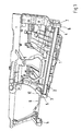
- Fig. 1
- in perspektivischer Ansicht eine erfindungsgemäße Abstützung für ein Knieairbaggehäuse eines Kraftfahrzeuges,
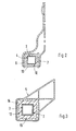
- Fig. 2
- einen Querschnitt durch eine äußere Abstützung der Stützstrebe nach einer bevorzugten Ausführungsform der Erfindung,
- Fig. 3
- einen Querschnitt durch eine innere Abstützung der Stützstrebe nach einer bevorzugten Ausführungsform der Erfindung,
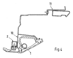
- Fig. 4
- einen Querschnitt durch eine Abstützung für ein Knieairbaggehäuse eines Kraftfahrzeuges nach einer bevorzugten Ausführungsform der Erfindung.
- Fig. 1
- a perspective view of a support according to the invention for a knee airbag housing of a motor vehicle,
- Fig. 2
- a cross section through an outer support of the support strut according to a preferred embodiment of the invention,
- Fig. 3
- a cross section through an inner support of the support strut according to a preferred embodiment of the invention,
- Fig. 4
- a cross section through a support for a knee airbag housing of a motor vehicle according to a preferred embodiment of the invention.
In
In einem inneren Bereich 3 des Fahrzeugs nimmt das Abstützelement 5 ein erstes Ende der Stützstrebe 2 auf. Das Abstützelement 5 ist wiederum durch eine Mittelstrebe 8 und ein Tragrahmenelement 9 mit einem Mitteltunnel (nicht gezeigt) des Fahrzeugs verbunden. In einem äußeren Bereich des Fahrzeugs, sowohl an der Fahrerseite als auch an der Beifahrerseite, nehmen die Tragelemente 6, 7 ein zweites Ende der Stützstrebe 2 auf.In an
In
Das Knieairbaggehäuse 1 ist mit der Stützstrebe 2 verbunden, vorzugsweise verschraubt. Wie aus der
Bei einer Auslösung des Knieairbags oder einer Knieintrusion wird die Kraft folglich in die Stützstrebe 2 und in die Tragrahmenelemente 5, 6, 7 geleitet.Upon initiation of the knee airbag or knee intrusion, the force is thus directed into the
In
Durch das elastische Element 12 ist die Stützstrebe 2 in den Tragrahmenelemente 6, 7 schwimmend gelagert. Da die Stützstrebe 2 nicht verschraubt oder verschweißt, sondern lose mit den Tragrahmenelementen 6, 7 elastisch verbunden ist, werden auftretende Toleranzen nicht negativ beeinflusst und Fugenmaße können eingehalten werden. Durch die Lagerung der Stützstrebe 2 mit dem elastischen Element 12 in den Tragrahmenelementen 6, 7 ist der geforderte Toleranzausgleich gewährleistet und es wird außerdem eine Geräuschbildung verhindert. Nur im Auslösefall des Knieairbags oder bei einer Knieintrusion nimmt der Montagewinkel die Reaktionskräfte auf und wirkt abstützend, indem die elastische Lagerung auf Block geht und die Stützstrebe eine kraftschlüssige Verbindung mit dem Montagewinkel eingeht und die Kraft in den Tragrahmen einleitet. Das elastische Element 12, vorzugsweise aus Gummi, ist entsprechend dem auftretenden Kraftverhältnis ausgelegt.By the
In
Durch die elastische Abstützung der Stützstrebe 2 wird sich die Stützstrebe 2 im Fall eines Crashs nur deformieren bzw. in der elastischen Abstützung verlagern bzw. sich elastisch abstützen. Da die Stützstrebe 2 nicht mit dem Tragrahmen verschweißt oder verschraubt ist, ist nur ein einfacher Austausch der Stützstrebe 2 erforderlich. Außerdem werden bei der elastischen Lagerung der Stützstrebe 2 auftretende Toleranzen nicht negative beeinflusst und Fugenmaße können eingehalten werden. Darüberhinaus wird eine Geräuschbildung durch die elastischen Elementen 12 verhindert.Due to the elastic support of the
Die vorhergehende Beschreibung der Ausführungsbeispiele gemäß der vorliegenden Erfindung dient nur zu illustrativen Zwecken und nicht zum Zwecke der Beschränkung der Erfindung. Insbesondere im Hinblick auf einige bevorzugte Ausführungsbeispiele entnimmt ihr der Fachmann, dass verschiedene Änderungen und Modifikationen in Gestalt und Einzelheiten gemacht werden können, ohne von dem Gedanken und Umfang der Erfindung abzuweichen. Dementsprechend soll die Offenbarung der vorliegenden Erfindung nicht einschränkend sein. Stattdessen soll die Offenbarung der vorliegenden Erfindung den Umfang der Erfindung veranschaulichen, der in den nachfolgenden Ansprüchen dargelegt ist.The foregoing description of the embodiments according to the present invention is for illustrative purposes only, and not for the purpose of limiting the invention. With particular reference to some preferred embodiments, those skilled in the art will appreciate that various changes and modifications in form and detail may be made without departing from the spirit and scope of the invention. Accordingly, the disclosure of the present invention is not intended to be limiting. Instead, the disclosure of the present invention is intended to illustrate the scope of the invention, which is set forth in the following claims.
Claims (11)
Applications Claiming Priority (1)
| Application Number | Priority Date | Filing Date | Title |
|---|---|---|---|
| DE102007031406A DE102007031406A1 (en) | 2007-07-05 | 2007-07-05 | Support for an airbag housing of a motor vehicle |
Publications (3)
| Publication Number | Publication Date |
|---|---|
| EP2011702A2 true EP2011702A2 (en) | 2009-01-07 |
| EP2011702A3 EP2011702A3 (en) | 2012-04-04 |
| EP2011702B1 EP2011702B1 (en) | 2015-02-11 |
Family
ID=39671748
Family Applications (1)
| Application Number | Title | Priority Date | Filing Date |
|---|---|---|---|
| EP08010656.0A Ceased EP2011702B1 (en) | 2007-07-05 | 2008-06-12 | Support for a vehicle airbag |
Country Status (3)
| Country | Link |
|---|---|
| US (1) | US7905309B2 (en) |
| EP (1) | EP2011702B1 (en) |
| DE (1) | DE102007031406A1 (en) |
Families Citing this family (2)
| Publication number | Priority date | Publication date | Assignee | Title |
|---|---|---|---|---|
| US20130006821A1 (en) * | 2011-06-30 | 2013-01-03 | United Parcel Service Of America, Inc. | Systems and methods for importing items |
| JP7104892B2 (en) * | 2018-03-29 | 2022-07-22 | マツダ株式会社 | Mounting structure for vehicle knee airbag device |
Citations (1)
| Publication number | Priority date | Publication date | Assignee | Title |
|---|---|---|---|---|
| DE10312597A1 (en) | 2003-03-21 | 2004-09-30 | Adam Opel Ag | Cladding for vehicle airbag housing has device attached to body for introducing and taking up reaction forces during inflation and supporting forces during impact that interacts with cladding |
Family Cites Families (14)
| Publication number | Priority date | Publication date | Assignee | Title |
|---|---|---|---|---|
| US2549925A (en) * | 1947-05-12 | 1951-04-24 | Clyde R Paton | Motor vehicle |
| JPS5073129U (en) * | 1973-11-07 | 1975-06-26 | ||
| DE4426785C1 (en) * | 1994-07-28 | 1995-08-24 | Opel Adam Ag | Motor vehicle body with integrated structural transverse strut |
| DE19728557B4 (en) * | 1996-07-16 | 2006-04-27 | Volkswagen Ag | Fastening arrangement for a cross member in a vehicle |
| GB2328393A (en) * | 1997-08-21 | 1999-02-24 | Rover Group | Securing components together and a structural member so formed |
| US5934733A (en) * | 1997-12-19 | 1999-08-10 | General Motors Corporation | Extruded instrument panel structure |
| US5960673A (en) * | 1998-04-02 | 1999-10-05 | Chrysler Corporation | Isolator pad for a steering column |
| JP3428547B2 (en) * | 2000-01-20 | 2003-07-22 | 本田技研工業株式会社 | Pipe reinforcement structure |
| DE10112738C1 (en) * | 2001-03-16 | 2002-06-20 | Benteler Automobiltechnik Gmbh | Instrument carrier for automobile provided with active oscillation damping via regulated piezo elements |
| JP4571341B2 (en) * | 2001-06-18 | 2010-10-27 | 水島プレス工業株式会社 | Damper mechanism of steering device |
| US6951348B2 (en) * | 2002-10-24 | 2005-10-04 | Autoliv Asp, Inc. | Rigid airbag plate attachment system |
| DE10340248B4 (en) * | 2003-08-29 | 2007-11-08 | Siemens Ag | Cross member and method for producing such |
| DE102004013343B4 (en) * | 2004-03-17 | 2006-02-09 | Benteler Automobiltechnik Gmbh | Dashboard carrying device, comprising several vibration absorbing elements made of memory metal |
| DE102004013342B3 (en) * | 2004-03-17 | 2005-09-22 | Benteler Automobiltechnik Gmbh | Instrument panel support |
-
2007
- 2007-07-05 DE DE102007031406A patent/DE102007031406A1/en not_active Withdrawn
-
2008
- 2008-06-12 EP EP08010656.0A patent/EP2011702B1/en not_active Ceased
- 2008-07-07 US US12/168,318 patent/US7905309B2/en active Active
Patent Citations (1)
| Publication number | Priority date | Publication date | Assignee | Title |
|---|---|---|---|---|
| DE10312597A1 (en) | 2003-03-21 | 2004-09-30 | Adam Opel Ag | Cladding for vehicle airbag housing has device attached to body for introducing and taking up reaction forces during inflation and supporting forces during impact that interacts with cladding |
Also Published As
| Publication number | Publication date |
|---|---|
| US20090008911A1 (en) | 2009-01-08 |
| US7905309B2 (en) | 2011-03-15 |
| EP2011702B1 (en) | 2015-02-11 |
| EP2011702A3 (en) | 2012-04-04 |
| DE102007031406A1 (en) | 2009-01-08 |
Similar Documents
| Publication | Publication Date | Title |
|---|---|---|
| DE3117378C2 (en) | Suspension for a drive unit of a motor vehicle which is arranged at the front, in particular transversely | |
| EP1880925B1 (en) | Motor vehicle with a supporting structure comprising longitudinal and transversal beams | |
| DE102008039972A1 (en) | Front structure of a motor vehicle | |
| DE19728557B4 (en) | Fastening arrangement for a cross member in a vehicle | |
| DE102007056673A1 (en) | body structure | |
| DE10038812A1 (en) | Car front cover cladding is stiffened at the cladding opening from below by a sheet metal or plastics stiffening element bonded to cladding. | |
| DE102009053369B4 (en) | Motor vehicle | |
| DE10329906B4 (en) | Bonnet system | |
| DE102008056501B4 (en) | Automotive body | |
| DE2353632C3 (en) | Bracket for the dashboard and the steering column in motor vehicles | |
| EP1300323A2 (en) | Vehicle body element with a large surface | |
| EP2011702B1 (en) | Support for a vehicle airbag | |
| DE102006033606B4 (en) | Arrangement for fastening a steering column of a motor vehicle | |
| DE19706225C2 (en) | Motor vehicle with a support between the cross member and splash guard | |
| EP1600338B1 (en) | Vehicle with deformable energy absorbing member | |
| DE102009040335A1 (en) | Holding arrangement for windscreen of motor vehicle i.e. passenger car, has connecting element comprising holding region for fastening windscreen, where holding region is arranged in vertical distance above closed hollow profile | |
| DE102004017631A1 (en) | Safety device for a motor vehicle with a front structure | |
| DE102013105142A1 (en) | Front wall for a motor vehicle | |
| DE102011055342B4 (en) | Body side structure | |
| DE102007049134B4 (en) | Shot channel for an airbag | |
| DE102008027199B4 (en) | Transverse stiffening structure for a motor vehicle | |
| DE102020007647A1 (en) | Vehicle body | |
| DE102023121184B4 (en) | Side door for a motor vehicle | |
| DE19543706A1 (en) | Door framework of motor vehicle | |
| DE19813752B4 (en) | crash element |
Legal Events
| Date | Code | Title | Description |
|---|---|---|---|
| PUAI | Public reference made under article 153(3) epc to a published international application that has entered the european phase |
Free format text: ORIGINAL CODE: 0009012 |
|
| AK | Designated contracting states |
Kind code of ref document: A2 Designated state(s): AT BE BG CH CY CZ DE DK EE ES FI FR GB GR HR HU IE IS IT LI LT LU LV MC MT NL NO PL PT RO SE SI SK TR |
|
| AX | Request for extension of the european patent |
Extension state: AL BA MK RS |
|
| RAP1 | Party data changed (applicant data changed or rights of an application transferred) |
Owner name: DR. ING. H.C. F. PORSCHE AG |
|
| PUAL | Search report despatched |
Free format text: ORIGINAL CODE: 0009013 |
|
| AK | Designated contracting states |
Kind code of ref document: A3 Designated state(s): AT BE BG CH CY CZ DE DK EE ES FI FR GB GR HR HU IE IS IT LI LT LU LV MC MT NL NO PL PT RO SE SI SK TR |
|
| AX | Request for extension of the european patent |
Extension state: AL BA MK RS |
|
| RIC1 | Information provided on ipc code assigned before grant |
Ipc: B60R 21/205 20110101AFI20120301BHEP |
|
| 17P | Request for examination filed |
Effective date: 20121004 |
|
| AKX | Designation fees paid |
Designated state(s): DE FR GB IT |
|
| 17Q | First examination report despatched |
Effective date: 20130110 |
|
| GRAP | Despatch of communication of intention to grant a patent |
Free format text: ORIGINAL CODE: EPIDOSNIGR1 |
|
| INTG | Intention to grant announced |
Effective date: 20141017 |
|
| GRAS | Grant fee paid |
Free format text: ORIGINAL CODE: EPIDOSNIGR3 |
|
| GRAA | (expected) grant |
Free format text: ORIGINAL CODE: 0009210 |
|
| AK | Designated contracting states |
Kind code of ref document: B1 Designated state(s): DE FR GB IT |
|
| REG | Reference to a national code |
Ref country code: GB Ref legal event code: FG4D Free format text: NOT ENGLISH |
|
| REG | Reference to a national code |
Ref country code: DE Ref legal event code: R096 Ref document number: 502008012656 Country of ref document: DE Effective date: 20150319 |
|
| REG | Reference to a national code |
Ref country code: DE Ref legal event code: R097 Ref document number: 502008012656 Country of ref document: DE |
|
| PLBE | No opposition filed within time limit |
Free format text: ORIGINAL CODE: 0009261 |
|
| STAA | Information on the status of an ep patent application or granted ep patent |
Free format text: STATUS: NO OPPOSITION FILED WITHIN TIME LIMIT |
|
| PG25 | Lapsed in a contracting state [announced via postgrant information from national office to epo] |
Ref country code: IT Free format text: LAPSE BECAUSE OF FAILURE TO SUBMIT A TRANSLATION OF THE DESCRIPTION OR TO PAY THE FEE WITHIN THE PRESCRIBED TIME-LIMIT Effective date: 20150211 |
|
| 26N | No opposition filed |
Effective date: 20151112 |
|
| REG | Reference to a national code |
Ref country code: FR Ref legal event code: PLFP Year of fee payment: 9 |
|
| REG | Reference to a national code |
Ref country code: FR Ref legal event code: PLFP Year of fee payment: 10 |
|
| REG | Reference to a national code |
Ref country code: FR Ref legal event code: PLFP Year of fee payment: 11 |
|
| PGFP | Annual fee paid to national office [announced via postgrant information from national office to epo] |
Ref country code: FR Payment date: 20190619 Year of fee payment: 12 |
|
| PGFP | Annual fee paid to national office [announced via postgrant information from national office to epo] |
Ref country code: GB Payment date: 20190619 Year of fee payment: 12 |
|
| GBPC | Gb: european patent ceased through non-payment of renewal fee |
Effective date: 20200612 |
|
| PG25 | Lapsed in a contracting state [announced via postgrant information from national office to epo] |
Ref country code: GB Free format text: LAPSE BECAUSE OF NON-PAYMENT OF DUE FEES Effective date: 20200612 Ref country code: FR Free format text: LAPSE BECAUSE OF NON-PAYMENT OF DUE FEES Effective date: 20200630 |
|
| P01 | Opt-out of the competence of the unified patent court (upc) registered |
Effective date: 20230526 |
|
| PGFP | Annual fee paid to national office [announced via postgrant information from national office to epo] |
Ref country code: DE Payment date: 20240524 Year of fee payment: 17 |
|
| REG | Reference to a national code |
Ref country code: DE Ref legal event code: R119 Ref document number: 502008012656 Country of ref document: DE |
|
| PG25 | Lapsed in a contracting state [announced via postgrant information from national office to epo] |
Ref country code: DE Free format text: LAPSE BECAUSE OF NON-PAYMENT OF DUE FEES Effective date: 20260101 |