EP2011189B1 - Messende armatur - Google Patents
Messende armatur Download PDFInfo
- Publication number
- EP2011189B1 EP2011189B1 EP07734341A EP07734341A EP2011189B1 EP 2011189 B1 EP2011189 B1 EP 2011189B1 EP 07734341 A EP07734341 A EP 07734341A EP 07734341 A EP07734341 A EP 07734341A EP 2011189 B1 EP2011189 B1 EP 2011189B1
- Authority
- EP
- European Patent Office
- Prior art keywords
- plug
- faucet
- electrical
- sensing
- valve body
- Prior art date
- Legal status (The legal status is an assumption and is not a legal conclusion. Google has not performed a legal analysis and makes no representation as to the accuracy of the status listed.)
- Not-in-force
Links
- 239000012530 fluid Substances 0.000 claims description 3
- 230000004913 activation Effects 0.000 claims description 2
- 230000009849 deactivation Effects 0.000 claims description 2
- 210000002435 tendon Anatomy 0.000 description 5
- 238000009434 installation Methods 0.000 description 4
- 239000004020 conductor Substances 0.000 description 2
- 230000001419 dependent effect Effects 0.000 description 1
- 230000000881 depressing effect Effects 0.000 description 1
- 238000005516 engineering process Methods 0.000 description 1
- 239000003566 sealing material Substances 0.000 description 1
- 239000008400 supply water Substances 0.000 description 1
Images


Classifications
-
- H—ELECTRICITY
- H01—ELECTRIC ELEMENTS
- H01M—PROCESSES OR MEANS, e.g. BATTERIES, FOR THE DIRECT CONVERSION OF CHEMICAL ENERGY INTO ELECTRICAL ENERGY
- H01M50/00—Constructional details or processes of manufacture of the non-active parts of electrochemical cells other than fuel cells, e.g. hybrid cells
- H01M50/50—Current conducting connections for cells or batteries
-
- E—FIXED CONSTRUCTIONS
- E03—WATER SUPPLY; SEWERAGE
- E03C—DOMESTIC PLUMBING INSTALLATIONS FOR FRESH WATER OR WASTE WATER; SINKS
- E03C1/00—Domestic plumbing installations for fresh water or waste water; Sinks
- E03C1/02—Plumbing installations for fresh water
- E03C1/05—Arrangements of devices on wash-basins, baths, sinks, or the like for remote control of taps
- E03C1/055—Electrical control devices, e.g. with push buttons, control panels or the like
- E03C1/057—Electrical control devices, e.g. with push buttons, control panels or the like touchless, i.e. using sensors
-
- F—MECHANICAL ENGINEERING; LIGHTING; HEATING; WEAPONS; BLASTING
- F16—ENGINEERING ELEMENTS AND UNITS; GENERAL MEASURES FOR PRODUCING AND MAINTAINING EFFECTIVE FUNCTIONING OF MACHINES OR INSTALLATIONS; THERMAL INSULATION IN GENERAL
- F16K—VALVES; TAPS; COCKS; ACTUATING-FLOATS; DEVICES FOR VENTING OR AERATING
- F16K31/00—Actuating devices; Operating means; Releasing devices
- F16K31/02—Actuating devices; Operating means; Releasing devices electric; magnetic
- F16K31/04—Actuating devices; Operating means; Releasing devices electric; magnetic using a motor
- F16K31/05—Actuating devices; Operating means; Releasing devices electric; magnetic using a motor specially adapted for operating hand-operated valves or for combined motor and hand operation
-
- H—ELECTRICITY
- H01—ELECTRIC ELEMENTS
- H01M—PROCESSES OR MEANS, e.g. BATTERIES, FOR THE DIRECT CONVERSION OF CHEMICAL ENERGY INTO ELECTRICAL ENERGY
- H01M50/00—Constructional details or processes of manufacture of the non-active parts of electrochemical cells other than fuel cells, e.g. hybrid cells
- H01M50/20—Mountings; Secondary casings or frames; Racks, modules or packs; Suspension devices; Shock absorbers; Transport or carrying devices; Holders
- H01M50/251—Mountings; Secondary casings or frames; Racks, modules or packs; Suspension devices; Shock absorbers; Transport or carrying devices; Holders specially adapted for stationary devices, e.g. power plant buffering or backup power supplies
-
- H—ELECTRICITY
- H01—ELECTRIC ELEMENTS
- H01R—ELECTRICALLY-CONDUCTIVE CONNECTIONS; STRUCTURAL ASSOCIATIONS OF A PLURALITY OF MUTUALLY-INSULATED ELECTRICAL CONNECTING ELEMENTS; COUPLING DEVICES; CURRENT COLLECTORS
- H01R12/00—Structural associations of a plurality of mutually-insulated electrical connecting elements, specially adapted for printed circuits, e.g. printed circuit boards [PCB], flat or ribbon cables, or like generally planar structures, e.g. terminal strips, terminal blocks; Coupling devices specially adapted for printed circuits, flat or ribbon cables, or like generally planar structures; Terminals specially adapted for contact with, or insertion into, printed circuits, flat or ribbon cables, or like generally planar structures
- H01R12/70—Coupling devices
- H01R12/71—Coupling devices for rigid printing circuits or like structures
- H01R12/712—Coupling devices for rigid printing circuits or like structures co-operating with the surface of the printed circuit or with a coupling device exclusively provided on the surface of the printed circuit
- H01R12/714—Coupling devices for rigid printing circuits or like structures co-operating with the surface of the printed circuit or with a coupling device exclusively provided on the surface of the printed circuit with contacts abutting directly the printed circuit; Button contacts therefore provided on the printed circuit
-
- H—ELECTRICITY
- H01—ELECTRIC ELEMENTS
- H01R—ELECTRICALLY-CONDUCTIVE CONNECTIONS; STRUCTURAL ASSOCIATIONS OF A PLURALITY OF MUTUALLY-INSULATED ELECTRICAL CONNECTING ELEMENTS; COUPLING DEVICES; CURRENT COLLECTORS
- H01R13/00—Details of coupling devices of the kinds covered by groups H01R12/70 or H01R24/00 - H01R33/00
- H01R13/02—Contact members
- H01R13/22—Contacts for co-operating by abutting
- H01R13/24—Contacts for co-operating by abutting resilient; resiliently-mounted
- H01R13/2407—Contacts for co-operating by abutting resilient; resiliently-mounted characterized by the resilient means
- H01R13/2421—Contacts for co-operating by abutting resilient; resiliently-mounted characterized by the resilient means using coil springs
-
- Y—GENERAL TAGGING OF NEW TECHNOLOGICAL DEVELOPMENTS; GENERAL TAGGING OF CROSS-SECTIONAL TECHNOLOGIES SPANNING OVER SEVERAL SECTIONS OF THE IPC; TECHNICAL SUBJECTS COVERED BY FORMER USPC CROSS-REFERENCE ART COLLECTIONS [XRACs] AND DIGESTS
- Y02—TECHNOLOGIES OR APPLICATIONS FOR MITIGATION OR ADAPTATION AGAINST CLIMATE CHANGE
- Y02E—REDUCTION OF GREENHOUSE GAS [GHG] EMISSIONS, RELATED TO ENERGY GENERATION, TRANSMISSION OR DISTRIBUTION
- Y02E60/00—Enabling technologies; Technologies with a potential or indirect contribution to GHG emissions mitigation
- Y02E60/10—Energy storage using batteries
Definitions
- Publicly known sensing faucet installation structures basically consist of two types.
- One type has the electric control box and battery compartment directly installed onto the valve body, and a faucet shell is used to cover them.
- the battery compartment should be installed at a position that can be directly disassembled. If the faucet is limited to a small diameter of tens of millimeters, it is very hard to design a suitable structure.
- the other type has the electric control box and battery compartment installed onto the faucet shell, which moves together with the electric control box and battery compartment during installation and disassembling.
- Such a structure may not be convenient for installation and disassembling.
- a self-closing faucet is disclosed in WO-A-99/22080 in which an actuator assembly mounted on the valve body is operable by a user depressing a top cap to actuate a switch that triggers a timer circuit to operate a solenoid valve to supply water to an outlet fitting of the faucet for a predetermined interval of time.
- a battery for supplying power to the timer circuit can be accessed by removing the top cap and a cover.
- An electrical connector is disclosed in DE-A-10048763 in which a plug is removably received in a socket to connect a wire harness to strip conductors.
- the socket has a male part and a female part connected together by interlocking lugs and recesses to maintain contact between contact pins on the male part and the strip conductors both when the plug is inserted in the socket and when the plug is removed from the socket.
- the present invention provides a new type of faucet structure, which not only is less demanding to the faucet's outer look, but also provides convenient disassembling. At the same time, stable function and service life can be guaranteed.
- the present invention provides a sensing faucet as defined in claim 1. Preferred features of the sensing faucet are the subject of the dependent claims.
- a preferred embodiment of the present invention may provide the electric control box and battery compartment installed onto the faucet shell.
- a connector is installed at the lower part of the battery compartment, and a plug seat is installed onto the faucet valve body.
- the plug preferably has 2 pins with internal springs, and the pins are installed in a rubber stopper. The tip of the pins can withdraw when pressed so that vertical tolerance can be removed.
- 2 guide pins on the valve body engage grooves on the faucet shell so that the plug can be lined up and directed into aligned engagement with the plug seat.
- the pins directly press an electric panel inside the plug seat; at the same time, there are circular tendons around a rubber stopper to form a seal.
- the faucet shell can be directly pulled out and the plug automatically detaches the plug seat. This arrangement is very convenient.
- Drawing Figure 1 is an illustration of the assembled sensing faucet, with a cut-out view of the faucet shell.
- Drawing Figure 2 is a cut-out illustration of the faucet shell components.
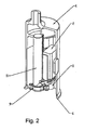
- Drawing Figure 3 is an illustration of the valve body assembly.
- Drawing Figure 4 is a cross-sectional illustration of the plug.
- faucet shell 1. electric control box; 3. plug seat; 4. plug; 5. guide pin; 6. positioning groove; 7. mounting screw; 8. valve body; 9. mounting screw; 10. wire protection cover ; 11. battery compartment assembly; 12. solenoid valve; 13. outlet pipe; 14. circular tendons; 15. electrical pins; 16. springs; 17. electric panel
- the faucet shell 1 is shown mounted on the valve body 8. proper alignment of the faucet shell 1 and the valve body 8 is provided by sliding engagement of the guide pin 5 into the positioning groove 6.
- the plug 4 is inserted into the plug seat 3 in this installed position, to provide an electrical connection therebetween.
- the electrical connection between the plug 4 and plug seat 3 allows power from batteries within the battery compartment assembly 11 to operate the solenoid valve 12 when power is activated by electric control box 2 which switches power on and off.
- the electric control box 2 may also include a sensor, the activation and deactivation of which switches the power on and off.
- the sensor may preferably be a motion or proximity sensor.
- Figure 2 depicts a cut-out view of only the faucet shell 1 portion, with installed battery compartment assembly 11, electric control box 2, and plug seat 3. Mounting screws 9 may be utilized to removably install these components within the faucet shell 1.
- Figure 3 depicts only the valve body 8 portion, with installed solenoid valve 12 and plug 4.
- the solenoid valve 12 and plug 4 are electrically connected.
- a wire protection cover 10 may be provided to protect the electrical connection.
- Mounting screws 7 may be provided to removably install these components onto the valve body 8.
- a fluid inlet (not shown) may be fluidly connected to the valve body 8.
- the solenoid valve 12 opens and closes a valve, permitting or restricting fluid flow into and through outlet pipe 13.
- Figure 4 is a cross-sectional view of the plug 4 and plug seat 3.
- the plug 4 has at least one electric pin 15 which is spring loaded by a spring 16 to allow movement in the longitudinal axial direction.
- the spring loaded electric pin 15 allows for electrical contact to be maintained with the electric panel 17 in the plug seat 3 when the plug 4 is inserted into the plug seat 3.
- the plug 4 being mounted on the valve body 8
- the plug seat 3 being mounted on the faucet shell 1
- the relative positions of the plug 4 and plug seat 3 may be switched.
- Figures 3 and 4 depict the plug 4 as having optional circular tendons 14 that serve as a seal member between the plug 4 and plug seat 3.
- the circular tendons may be made of rubber or a similar sealing material.
- the circular tendons 14 may be formed on either or both of the plug 4 and plug seat 3.
- the electric pin(s) 15 in the plug 4 and the electric panel(s) 17 in the plug seat 3 the electric pin(s) 15 and the electric panel(s) 17 may be formed on either the plug 4 or plug seat 3.
Landscapes
- Engineering & Computer Science (AREA)
- Chemical Kinetics & Catalysis (AREA)
- Electrochemistry (AREA)
- General Chemical & Material Sciences (AREA)
- Chemical & Material Sciences (AREA)
- Public Health (AREA)
- Life Sciences & Earth Sciences (AREA)
- Hydrology & Water Resources (AREA)
- Health & Medical Sciences (AREA)
- Water Supply & Treatment (AREA)
- General Engineering & Computer Science (AREA)
- Mechanical Engineering (AREA)
- Domestic Plumbing Installations (AREA)
- Details Of Connecting Devices For Male And Female Coupling (AREA)
- Connector Housings Or Holding Contact Members (AREA)
- Valve Housings (AREA)
Claims (11)
- Eine messende Armatur bestehend aus:einem Armaturengehäuse (1) mit einem Schaltkasten (2) und einem Batteriefach (11);einem Ventilkörper (8) mit einem Magnetventil (12); understen und zweiten elektrischen Anschlusskomponenten (3, 4),dadurch gekennzeichnet, dassder Schaltkasten (2) einen Bewegungs- oder Nähesensor aufweist;wobei die erste elektrische Anschlusskomponente eine Steckbuchse (3) und die zweite elektrische Anschlusskomponente eine Stecker (4) ist;wobei eine der elektrischen Anschlusskomponenten (3, 4) am Armaturengehäuse (1) positioniert ist und die anderen elektrische Anschlusskomponente (3, 4) am Ventilkörper (8) positioniert ist;wobei zumindest eine Schaltplatte (17) entweder am Stecker (4) oder an der Steckbuchse (3) angeordnet ist und zumindest ein gefederter elektrischer Stift (15) am verbleibenden Stecker (4) oder an der Steckbuchse (3) angeordnet ist;wobei der Stecker (4) entfernbar in einer Steckeraufnahmeposition in der Steckbuchse (3) in einer installierten Position des Armaturengehäuses (1) am Ventilkörper (8) aufgenommen wird;wobei eine Spitze des zumindest einen gefederten elektrischen Stifts (15) so angeordnet ist, dass sie mit der zumindest einen Schaltplatte (17) in Kontakt ist, wenn der Stecker (4) in der Steckbuchse (3) in der Steckeraufnahmeposition aufgenommen wird, um hierdurch einen elektrischen Anschluss zu erstellen, der den Betrieb des Magnetventils (12) ermöglicht, wenn durch den Schaltkasten (2) Strom eingeschaltet wird; undwobei der Stecker (4) bei Ausbau des Armaturengehäuses (1) die Steckbuchse (3) automatisch trennt.
- Eine messende Armatur entsprechend Anspruch 1, wobei im Stecker (4) zwei gefederte elektrische Stifte (15) vorgesehen sind.
- Die messende Armatur entsprechend Anspruch 1, wobei zumindest entweder der Stecker (4) oder die Steckbuchse (3) mit einer Dichtung (14) versehen ist, die, wenn der Stecker in der Steckeraufnahmeposition in der Steckbuchse (3) ist, zwischen dem Stecker (4) und der Steckbuchse (3) positioniert ist.
- Die messende Armatur entsprechend Anspruch 3, wobei die Dichtung (14) am Stecker (4) vorgesehen ist.
- Die messende Armatur entsprechend Anspruch 1, wobei die zumindest eine Schaltplatte (17) an der Steckbuchse (3) positioniert ist und der zumindest eine gefederte elektrische Stift (15) am Stecker (4) positioniert ist.
- Die messende Armatur entsprechend Anspruch 1, wobei die Steckbuchse (3) am Armaturengehäuse (1) vorgesehen und der Stecker (4) am Ventilkörper (8) vorgesehen ist.
- Die messende Armatur entsprechend Anspruch 1, zu der weiterhin ein Führungsstift (5) und eine Positionsnut (6) gehören, die ineinander geschoben werden, um Ausrichten und Positionieren des Armaturengehäuses (1) am Ventilkörper (8) zu ermöglichen, wobei der Führungsstift (5) am Armaturengehäuse (1) oder am Ventilkörper (8) positioniert und die Positionsnut (6) am verbleibenden Ventilkörper (1) oder Ventilköper (8) positioniert ist.
- Die messende Armatur entsprechend Anspruch 1, wobei der zumindest eine elektrische Stift (15) entlang einer Längsachse des zumindest einen elektrischen Stifts (15) bewegt werden kann.
- Die messende Armatur entsprechend Anspruch 1, wobei das Magnetventil (12) ein Ventil öffnet und schließt, um einen Flüssigkeitsstrom in und durch das Auslassrohr (13) zu ermöglichen oder einzuschränken.
- Die messende Armatur entsprechend Anspruch 1, wobei der elektrische Anschluss zwischen dem Stecker (4) und der Steckbuchse (3) ermöglicht, dass der Batteriestrom vom Batteriefach (11) das Magnetventil (12) operiert, wenn der Strom durch den Schaltkasten (2) eingeschaltet wird.
- Die messende Armatur entsprechend Anspruch 1, wobei ein Einschalten und Ausschalten des Sensors den Strom ein- und ausschaltet.
Applications Claiming Priority (2)
| Application Number | Priority Date | Filing Date | Title |
|---|---|---|---|
| CNU2006200411847U CN2886267Y (zh) | 2006-04-20 | 2006-04-20 | 感应龙头安装结构 |
| PCT/IB2007/001022 WO2007122476A1 (en) | 2006-04-20 | 2007-04-19 | Sensing faucet |
Publications (3)
| Publication Number | Publication Date |
|---|---|
| EP2011189A1 EP2011189A1 (de) | 2009-01-07 |
| EP2011189A4 EP2011189A4 (de) | 2012-02-29 |
| EP2011189B1 true EP2011189B1 (de) | 2013-03-27 |
Family
ID=37961357
Family Applications (1)
| Application Number | Title | Priority Date | Filing Date |
|---|---|---|---|
| EP07734341A Not-in-force EP2011189B1 (de) | 2006-04-20 | 2007-04-19 | Messende armatur |
Country Status (12)
| Country | Link |
|---|---|
| US (1) | US20090311914A1 (de) |
| EP (1) | EP2011189B1 (de) |
| JP (1) | JP2009534788A (de) |
| KR (1) | KR20090014262A (de) |
| CN (1) | CN2886267Y (de) |
| AU (1) | AU2007242565A1 (de) |
| BR (1) | BRPI0711258A2 (de) |
| CA (1) | CA2658013A1 (de) |
| MX (1) | MX2008013299A (de) |
| NZ (1) | NZ571996A (de) |
| RU (1) | RU2008145747A (de) |
| WO (1) | WO2007122476A1 (de) |
Families Citing this family (7)
| Publication number | Priority date | Publication date | Assignee | Title |
|---|---|---|---|---|
| CN1862249B (zh) | 2006-04-20 | 2012-01-04 | 上海科勒电子科技有限公司 | 干电池供电主动式红外感应器具的节能处理方法 |
| EP2169123B1 (de) | 2008-09-24 | 2014-12-31 | Geberit International AG | Berührungslos gesteuerte Wasserarmatur |
| US9032565B2 (en) | 2009-12-16 | 2015-05-19 | Kohler Co. | Touchless faucet assembly and method of operation |
| CN101713464B (zh) * | 2009-12-16 | 2012-01-04 | 上海科勒电子科技有限公司 | 自动出水控制装置及自动出水装置 |
| DE102019002259A1 (de) * | 2019-03-29 | 2020-10-01 | GROHEDAL Sanitärsysteme GmbH | Sanitärarmatur mit einer Steckereinheit |
| CN114370520B (zh) * | 2020-10-15 | 2025-01-10 | 路达(厦门)工业有限公司 | 龙头 |
| US12493355B2 (en) | 2022-04-14 | 2025-12-09 | Kohler Co. | Touchless plumbing control system |
Family Cites Families (30)
| Publication number | Priority date | Publication date | Assignee | Title |
|---|---|---|---|---|
| US2544448A (en) * | 1945-04-11 | 1951-03-06 | Aero Supply Mfg Co Inc | Motor operated valve shaft |
| DE2421321C3 (de) * | 1974-05-02 | 1978-05-11 | Georg Dipl.-Ing. Dr.-Ing. 8152 Feldkirchen-Westerham Spinner | Abgedichtete koaxiale Steckverbindungseinrichtung |
| DE3728589A1 (de) * | 1987-08-27 | 1989-03-09 | Bosch Gmbh Robert | Elektrischer stellmotor |
| JPH0721981Y2 (ja) * | 1989-01-13 | 1995-05-17 | 東陶機器株式会社 | 自動水栓における駆動部ユニット構造 |
| JPH06130489A (ja) * | 1992-10-16 | 1994-05-13 | Fuji Photo Optical Co Ltd | 赤外光式リモートコントローラを備えたカメラ |
| JP2585087Y2 (ja) * | 1993-10-14 | 1998-11-11 | 宇呂電子工業株式会社 | 自動洗浄装置 |
| US5381830A (en) * | 1994-01-18 | 1995-01-17 | Masco Corporation Of Indiana | Spout mounting system |
| US5456621A (en) * | 1994-02-01 | 1995-10-10 | Relm Communications, Inc. | Self-wiping/self cleaning electrical contact |
| DE4420330A1 (de) * | 1994-06-10 | 1995-12-14 | Grohe Armaturen Friedrich | Wasserarmatur mit elektrischer Steuerung |
| DE9412068U1 (de) * | 1994-07-26 | 1994-09-15 | Festo Kg, 73734 Esslingen | Verbindungseinrichtung zu elektrischen Verbindung von Kontaktelementen |
| US5473461A (en) * | 1994-08-26 | 1995-12-05 | Interactive Light, Inc. | Wide dynamic range optical receiver |
| JP3254545B2 (ja) * | 1994-11-04 | 2002-02-12 | ホシデン株式会社 | 防滴型ピンコネクタ |
| US5667410A (en) * | 1995-11-21 | 1997-09-16 | Everett Charles Technologies, Inc. | One-piece compliant probe |
| US5984262A (en) * | 1996-07-31 | 1999-11-16 | Arichell Technologies, Inc. | Object-sensor-based flow-control system employing fiber-optic signal transmission |
| US6020703A (en) * | 1997-06-30 | 2000-02-01 | Telmet; Juhan | Garage door opener |
| EP0995127B1 (de) * | 1997-07-18 | 2002-11-27 | Kohler Co. | Radarvorrichtung für niedrige leistungsverwendungen und sanitäranlagen |
| US5955888A (en) * | 1997-09-10 | 1999-09-21 | Xilinx, Inc. | Apparatus and method for testing ball grid array packaged integrated circuits |
| CN2311077Y (zh) * | 1997-09-30 | 1999-03-17 | 喻峰 | 新型插头插座组件 |
| US5911240A (en) * | 1997-10-27 | 1999-06-15 | Kohler Co. | Self-closing solenoid operated faucet |
| US5988588A (en) * | 1998-03-16 | 1999-11-23 | Asloan Valve Company | Control module for battery-operated faucet |
| US6202980B1 (en) * | 1999-01-15 | 2001-03-20 | Masco Corporation Of Indiana | Electronic faucet |
| US6082407A (en) * | 1999-03-03 | 2000-07-04 | Speakman Company | Automatic faucet assembly with mating housing and high endurance finish |
| US6261130B1 (en) * | 2000-01-19 | 2001-07-17 | Mhl Development Company, Inc. | High-density pogo pin connector |
| IT249712Y1 (it) * | 2000-01-24 | 2003-05-28 | Claber Spa | Elettrovalvola con dispositivo di controllo elettronico programmabileparticolarmente per impianti di irrigazione |
| DE10048763A1 (de) | 2000-09-29 | 2002-04-11 | 2 E Rolf Hiller Gmbh | Anordnung zur elektrischen Kontaktierung |
| CN2455985Y (zh) * | 2000-12-20 | 2001-10-24 | 隆门科技股份有限公司 | 自动龙头控制盒 |
| JP2003045603A (ja) * | 2001-08-01 | 2003-02-14 | Anfuenooru Japan Kk | コネクタ及びその製造方法 |
| CN2545727Y (zh) * | 2001-09-20 | 2003-04-16 | 广东德豪润达电气股份有限公司 | 无绳电连接器 |
| DE10211798A1 (de) * | 2002-03-16 | 2004-05-19 | Festo Ag & Co. | Kontaktierungseinrichtung für Ventilantriebe und damit ausgestattete Ventilanordnung |
| CN1320297C (zh) * | 2003-09-15 | 2007-06-06 | 周敏芳 | 感应式水龙头 |
-
2006
- 2006-04-20 CN CNU2006200411847U patent/CN2886267Y/zh not_active Expired - Fee Related
-
2007
- 2007-04-19 MX MX2008013299A patent/MX2008013299A/es not_active Application Discontinuation
- 2007-04-19 NZ NZ571996A patent/NZ571996A/en unknown
- 2007-04-19 KR KR1020087025448A patent/KR20090014262A/ko not_active Withdrawn
- 2007-04-19 CA CA002658013A patent/CA2658013A1/en not_active Abandoned
- 2007-04-19 EP EP07734341A patent/EP2011189B1/de not_active Not-in-force
- 2007-04-19 JP JP2009505988A patent/JP2009534788A/ja active Pending
- 2007-04-19 RU RU2008145747/09A patent/RU2008145747A/ru not_active Application Discontinuation
- 2007-04-19 US US12/297,465 patent/US20090311914A1/en not_active Abandoned
- 2007-04-19 AU AU2007242565A patent/AU2007242565A1/en not_active Abandoned
- 2007-04-19 WO PCT/IB2007/001022 patent/WO2007122476A1/en not_active Ceased
- 2007-04-19 BR BRPI0711258-0A patent/BRPI0711258A2/pt not_active IP Right Cessation
Also Published As
| Publication number | Publication date |
|---|---|
| EP2011189A1 (de) | 2009-01-07 |
| KR20090014262A (ko) | 2009-02-09 |
| AU2007242565A1 (en) | 2007-11-01 |
| CA2658013A1 (en) | 2007-11-01 |
| WO2007122476A1 (en) | 2007-11-01 |
| MX2008013299A (es) | 2009-02-25 |
| CN2886267Y (zh) | 2007-04-04 |
| NZ571996A (en) | 2010-09-30 |
| EP2011189A4 (de) | 2012-02-29 |
| RU2008145747A (ru) | 2010-05-27 |
| JP2009534788A (ja) | 2009-09-24 |
| BRPI0711258A2 (pt) | 2011-08-30 |
| US20090311914A1 (en) | 2009-12-17 |
Similar Documents
| Publication | Publication Date | Title |
|---|---|---|
| EP2011189B1 (de) | Messende armatur | |
| JP6522798B2 (ja) | 圧力制御された電気リレーデバイス | |
| CN215008830U (zh) | 一种导电能力强的轨道插座 | |
| CN108775407B (zh) | 出水阀结构及包括其的加湿器 | |
| WO2007133446A3 (en) | Fuel-cell connector | |
| CN111795164B (zh) | 一种出水阀 | |
| US9416562B2 (en) | Electronic key | |
| CN203562366U (zh) | 饮水器的流量开关 | |
| CN215483359U (zh) | 一种带手动控制功能的电磁冲水阀及电磁阀冲水装置 | |
| EP2090368A1 (de) | Verbesserter Duschkopf mit Umschaltung der Ausgabeart | |
| CN210290798U (zh) | 一种车用高压氢气瓶口阀 | |
| CN219914536U (zh) | 一种带泄压装置的水流传感器 | |
| CN216112426U (zh) | 一种电磁阀及四通阀 | |
| JP4843513B2 (ja) | コネクタ装置及び電動弁 | |
| CN210661473U (zh) | 一种燃气阀 | |
| JP2007149448A (ja) | 液体送受用ジョイント装置及びこれを備えた燃料電池システム | |
| KR20240000694A (ko) | 전기차용 전원공급소켓 | |
| CN207961708U (zh) | 一种电磁阀 | |
| CN222848758U (zh) | 一种电磁阀、燃气阀及燃气设备 | |
| CN223049846U (zh) | 一种用于高压瓶阀的电磁控制结构 | |
| CN112145724B (zh) | 一种车辆用应急阀 | |
| CN218493766U (zh) | 双核隔膜泵 | |
| KR100756219B1 (ko) | 사용시 압력에 안전한 열매체 보일러 | |
| CN212690908U (zh) | 角阀及出水装置 | |
| JP4253776B1 (ja) | 電動灯油ポンプ |
Legal Events
| Date | Code | Title | Description |
|---|---|---|---|
| PUAI | Public reference made under article 153(3) epc to a published international application that has entered the european phase |
Free format text: ORIGINAL CODE: 0009012 |
|
| 17P | Request for examination filed |
Effective date: 20081113 |
|
| AK | Designated contracting states |
Kind code of ref document: A1 Designated state(s): AT BE BG CH CY CZ DE DK EE ES FI FR GB GR HU IE IS IT LI LT LU LV MC MT NL PL PT RO SE SI SK TR |
|
| AX | Request for extension of the european patent |
Extension state: AL BA HR MK RS |
|
| REG | Reference to a national code |
Ref country code: DE Ref legal event code: R079 Ref document number: 602007029331 Country of ref document: DE Free format text: PREVIOUS MAIN CLASS: H01R0013150000 Ipc: E03C0001050000 |
|
| A4 | Supplementary search report drawn up and despatched |
Effective date: 20120201 |
|
| RIC1 | Information provided on ipc code assigned before grant |
Ipc: H01M 2/20 20060101ALI20120126BHEP Ipc: E03C 1/05 20060101AFI20120126BHEP Ipc: H01R 13/15 20060101ALI20120126BHEP Ipc: F16K 31/05 20060101ALI20120126BHEP Ipc: H01R 13/24 20060101ALI20120126BHEP |
|
| DAX | Request for extension of the european patent (deleted) | ||
| GRAP | Despatch of communication of intention to grant a patent |
Free format text: ORIGINAL CODE: EPIDOSNIGR1 |
|
| GRAS | Grant fee paid |
Free format text: ORIGINAL CODE: EPIDOSNIGR3 |
|
| GRAA | (expected) grant |
Free format text: ORIGINAL CODE: 0009210 |
|
| AK | Designated contracting states |
Kind code of ref document: B1 Designated state(s): AT BE BG CH CY CZ DE DK EE ES FI FR GB GR HU IE IS IT LI LT LU LV MC MT NL PL PT RO SE SI SK TR |
|
| REG | Reference to a national code |
Ref country code: GB Ref legal event code: FG4D |
|
| REG | Reference to a national code |
Ref country code: CH Ref legal event code: EP |
|
| REG | Reference to a national code |
Ref country code: AT Ref legal event code: REF Ref document number: 603507 Country of ref document: AT Kind code of ref document: T Effective date: 20130415 |
|
| REG | Reference to a national code |
Ref country code: IE Ref legal event code: FG4D |
|
| REG | Reference to a national code |
Ref country code: DE Ref legal event code: R096 Ref document number: 602007029331 Country of ref document: DE Effective date: 20130523 |
|
| PG25 | Lapsed in a contracting state [announced via postgrant information from national office to epo] |
Ref country code: BG Free format text: LAPSE BECAUSE OF FAILURE TO SUBMIT A TRANSLATION OF THE DESCRIPTION OR TO PAY THE FEE WITHIN THE PRESCRIBED TIME-LIMIT Effective date: 20130627 Ref country code: LT Free format text: LAPSE BECAUSE OF FAILURE TO SUBMIT A TRANSLATION OF THE DESCRIPTION OR TO PAY THE FEE WITHIN THE PRESCRIBED TIME-LIMIT Effective date: 20130327 Ref country code: SE Free format text: LAPSE BECAUSE OF FAILURE TO SUBMIT A TRANSLATION OF THE DESCRIPTION OR TO PAY THE FEE WITHIN THE PRESCRIBED TIME-LIMIT Effective date: 20130327 |
|
| PGFP | Annual fee paid to national office [announced via postgrant information from national office to epo] |
Ref country code: GB Payment date: 20130424 Year of fee payment: 7 Ref country code: DE Payment date: 20130508 Year of fee payment: 7 |
|
| REG | Reference to a national code |
Ref country code: AT Ref legal event code: MK05 Ref document number: 603507 Country of ref document: AT Kind code of ref document: T Effective date: 20130327 |
|
| REG | Reference to a national code |
Ref country code: LT Ref legal event code: MG4D |
|
| PG25 | Lapsed in a contracting state [announced via postgrant information from national office to epo] |
Ref country code: SI Free format text: LAPSE BECAUSE OF FAILURE TO SUBMIT A TRANSLATION OF THE DESCRIPTION OR TO PAY THE FEE WITHIN THE PRESCRIBED TIME-LIMIT Effective date: 20130327 Ref country code: FI Free format text: LAPSE BECAUSE OF FAILURE TO SUBMIT A TRANSLATION OF THE DESCRIPTION OR TO PAY THE FEE WITHIN THE PRESCRIBED TIME-LIMIT Effective date: 20130327 Ref country code: GR Free format text: LAPSE BECAUSE OF FAILURE TO SUBMIT A TRANSLATION OF THE DESCRIPTION OR TO PAY THE FEE WITHIN THE PRESCRIBED TIME-LIMIT Effective date: 20130628 Ref country code: LV Free format text: LAPSE BECAUSE OF FAILURE TO SUBMIT A TRANSLATION OF THE DESCRIPTION OR TO PAY THE FEE WITHIN THE PRESCRIBED TIME-LIMIT Effective date: 20130327 |
|
| PGFP | Annual fee paid to national office [announced via postgrant information from national office to epo] |
Ref country code: FR Payment date: 20130603 Year of fee payment: 7 |
|
| REG | Reference to a national code |
Ref country code: NL Ref legal event code: VDEP Effective date: 20130327 |
|
| PG25 | Lapsed in a contracting state [announced via postgrant information from national office to epo] |
Ref country code: BE Free format text: LAPSE BECAUSE OF FAILURE TO SUBMIT A TRANSLATION OF THE DESCRIPTION OR TO PAY THE FEE WITHIN THE PRESCRIBED TIME-LIMIT Effective date: 20130327 |
|
| PG25 | Lapsed in a contracting state [announced via postgrant information from national office to epo] |
Ref country code: PT Free format text: LAPSE BECAUSE OF FAILURE TO SUBMIT A TRANSLATION OF THE DESCRIPTION OR TO PAY THE FEE WITHIN THE PRESCRIBED TIME-LIMIT Effective date: 20130729 Ref country code: SK Free format text: LAPSE BECAUSE OF FAILURE TO SUBMIT A TRANSLATION OF THE DESCRIPTION OR TO PAY THE FEE WITHIN THE PRESCRIBED TIME-LIMIT Effective date: 20130327 Ref country code: CZ Free format text: LAPSE BECAUSE OF FAILURE TO SUBMIT A TRANSLATION OF THE DESCRIPTION OR TO PAY THE FEE WITHIN THE PRESCRIBED TIME-LIMIT Effective date: 20130327 Ref country code: AT Free format text: LAPSE BECAUSE OF FAILURE TO SUBMIT A TRANSLATION OF THE DESCRIPTION OR TO PAY THE FEE WITHIN THE PRESCRIBED TIME-LIMIT Effective date: 20130327 Ref country code: RO Free format text: LAPSE BECAUSE OF FAILURE TO SUBMIT A TRANSLATION OF THE DESCRIPTION OR TO PAY THE FEE WITHIN THE PRESCRIBED TIME-LIMIT Effective date: 20130327 Ref country code: EE Free format text: LAPSE BECAUSE OF FAILURE TO SUBMIT A TRANSLATION OF THE DESCRIPTION OR TO PAY THE FEE WITHIN THE PRESCRIBED TIME-LIMIT Effective date: 20130327 Ref country code: NL Free format text: LAPSE BECAUSE OF FAILURE TO SUBMIT A TRANSLATION OF THE DESCRIPTION OR TO PAY THE FEE WITHIN THE PRESCRIBED TIME-LIMIT Effective date: 20130327 Ref country code: ES Free format text: LAPSE BECAUSE OF FAILURE TO SUBMIT A TRANSLATION OF THE DESCRIPTION OR TO PAY THE FEE WITHIN THE PRESCRIBED TIME-LIMIT Effective date: 20130708 Ref country code: IS Free format text: LAPSE BECAUSE OF FAILURE TO SUBMIT A TRANSLATION OF THE DESCRIPTION OR TO PAY THE FEE WITHIN THE PRESCRIBED TIME-LIMIT Effective date: 20130727 |
|
| PG25 | Lapsed in a contracting state [announced via postgrant information from national office to epo] |
Ref country code: PL Free format text: LAPSE BECAUSE OF FAILURE TO SUBMIT A TRANSLATION OF THE DESCRIPTION OR TO PAY THE FEE WITHIN THE PRESCRIBED TIME-LIMIT Effective date: 20130327 Ref country code: CY Free format text: LAPSE BECAUSE OF FAILURE TO SUBMIT A TRANSLATION OF THE DESCRIPTION OR TO PAY THE FEE WITHIN THE PRESCRIBED TIME-LIMIT Effective date: 20130327 |
|
| REG | Reference to a national code |
Ref country code: CH Ref legal event code: PL |
|
| PG25 | Lapsed in a contracting state [announced via postgrant information from national office to epo] |
Ref country code: MC Free format text: LAPSE BECAUSE OF FAILURE TO SUBMIT A TRANSLATION OF THE DESCRIPTION OR TO PAY THE FEE WITHIN THE PRESCRIBED TIME-LIMIT Effective date: 20130327 |
|
| REG | Reference to a national code |
Ref country code: IE Ref legal event code: MM4A |
|
| PG25 | Lapsed in a contracting state [announced via postgrant information from national office to epo] |
Ref country code: CH Free format text: LAPSE BECAUSE OF NON-PAYMENT OF DUE FEES Effective date: 20130430 Ref country code: DK Free format text: LAPSE BECAUSE OF FAILURE TO SUBMIT A TRANSLATION OF THE DESCRIPTION OR TO PAY THE FEE WITHIN THE PRESCRIBED TIME-LIMIT Effective date: 20130327 Ref country code: LI Free format text: LAPSE BECAUSE OF NON-PAYMENT OF DUE FEES Effective date: 20130430 |
|
| PLBE | No opposition filed within time limit |
Free format text: ORIGINAL CODE: 0009261 |
|
| STAA | Information on the status of an ep patent application or granted ep patent |
Free format text: STATUS: NO OPPOSITION FILED WITHIN TIME LIMIT |
|
| PG25 | Lapsed in a contracting state [announced via postgrant information from national office to epo] |
Ref country code: IT Free format text: LAPSE BECAUSE OF FAILURE TO SUBMIT A TRANSLATION OF THE DESCRIPTION OR TO PAY THE FEE WITHIN THE PRESCRIBED TIME-LIMIT Effective date: 20130327 |
|
| 26N | No opposition filed |
Effective date: 20140103 |
|
| REG | Reference to a national code |
Ref country code: DE Ref legal event code: R097 Ref document number: 602007029331 Country of ref document: DE Effective date: 20140103 |
|
| PG25 | Lapsed in a contracting state [announced via postgrant information from national office to epo] |
Ref country code: IE Free format text: LAPSE BECAUSE OF NON-PAYMENT OF DUE FEES Effective date: 20130419 |
|
| REG | Reference to a national code |
Ref country code: DE Ref legal event code: R119 Ref document number: 602007029331 Country of ref document: DE |
|
| GBPC | Gb: european patent ceased through non-payment of renewal fee |
Effective date: 20140419 |
|
| REG | Reference to a national code |
Ref country code: DE Ref legal event code: R119 Ref document number: 602007029331 Country of ref document: DE Effective date: 20141101 |
|
| REG | Reference to a national code |
Ref country code: FR Ref legal event code: ST Effective date: 20141231 |
|
| PG25 | Lapsed in a contracting state [announced via postgrant information from national office to epo] |
Ref country code: DE Free format text: LAPSE BECAUSE OF NON-PAYMENT OF DUE FEES Effective date: 20141101 Ref country code: GB Free format text: LAPSE BECAUSE OF NON-PAYMENT OF DUE FEES Effective date: 20140419 |
|
| PG25 | Lapsed in a contracting state [announced via postgrant information from national office to epo] |
Ref country code: FR Free format text: LAPSE BECAUSE OF NON-PAYMENT OF DUE FEES Effective date: 20140430 Ref country code: MT Free format text: LAPSE BECAUSE OF FAILURE TO SUBMIT A TRANSLATION OF THE DESCRIPTION OR TO PAY THE FEE WITHIN THE PRESCRIBED TIME-LIMIT Effective date: 20130327 |
|
| PG25 | Lapsed in a contracting state [announced via postgrant information from national office to epo] |
Ref country code: TR Free format text: LAPSE BECAUSE OF FAILURE TO SUBMIT A TRANSLATION OF THE DESCRIPTION OR TO PAY THE FEE WITHIN THE PRESCRIBED TIME-LIMIT Effective date: 20130327 |
|
| PG25 | Lapsed in a contracting state [announced via postgrant information from national office to epo] |
Ref country code: HU Free format text: LAPSE BECAUSE OF FAILURE TO SUBMIT A TRANSLATION OF THE DESCRIPTION OR TO PAY THE FEE WITHIN THE PRESCRIBED TIME-LIMIT; INVALID AB INITIO Effective date: 20070419 Ref country code: LU Free format text: LAPSE BECAUSE OF NON-PAYMENT OF DUE FEES Effective date: 20130419 |