EP2011107B1 - Temperaturempfindliche indikatoren für prozessteuerinstrumente - Google Patents
Temperaturempfindliche indikatoren für prozessteuerinstrumente Download PDFInfo
- Publication number
- EP2011107B1 EP2011107B1 EP07751182.2A EP07751182A EP2011107B1 EP 2011107 B1 EP2011107 B1 EP 2011107B1 EP 07751182 A EP07751182 A EP 07751182A EP 2011107 B1 EP2011107 B1 EP 2011107B1
- Authority
- EP
- European Patent Office
- Prior art keywords
- transmitter
- layer
- temperature responsive
- variable
- process transmitter
- Prior art date
- Legal status (The legal status is an assumption and is not a legal conclusion. Google has not performed a legal analysis and makes no representation as to the accuracy of the status listed.)
- Active
Links
Images

Classifications
-
- G—PHYSICS
- G01—MEASURING; TESTING
- G01K—MEASURING TEMPERATURE; MEASURING QUANTITY OF HEAT; THERMALLY-SENSITIVE ELEMENTS NOT OTHERWISE PROVIDED FOR
- G01K11/00—Measuring temperature based upon physical or chemical changes not covered by groups G01K3/00, G01K5/00, G01K7/00 or G01K9/00
- G01K11/12—Measuring temperature based upon physical or chemical changes not covered by groups G01K3/00, G01K5/00, G01K7/00 or G01K9/00 using changes in colour, translucency or reflectance
- G01K11/16—Measuring temperature based upon physical or chemical changes not covered by groups G01K3/00, G01K5/00, G01K7/00 or G01K9/00 using changes in colour, translucency or reflectance of organic materials
- G01K11/165—Measuring temperature based upon physical or chemical changes not covered by groups G01K3/00, G01K5/00, G01K7/00 or G01K9/00 using changes in colour, translucency or reflectance of organic materials of organic liquid crystals
-
- G—PHYSICS
- G01—MEASURING; TESTING
- G01D—MEASURING NOT SPECIALLY ADAPTED FOR A SPECIFIC VARIABLE; ARRANGEMENTS FOR MEASURING TWO OR MORE VARIABLES NOT COVERED IN A SINGLE OTHER SUBCLASS; TARIFF METERING APPARATUS; MEASURING OR TESTING NOT OTHERWISE PROVIDED FOR
- G01D7/00—Indicating measured values
- G01D7/005—Indication of measured value by colour change
-
- G—PHYSICS
- G01—MEASURING; TESTING
- G01K—MEASURING TEMPERATURE; MEASURING QUANTITY OF HEAT; THERMALLY-SENSITIVE ELEMENTS NOT OTHERWISE PROVIDED FOR
- G01K3/00—Thermometers giving results other than momentary value of temperature
- G01K3/005—Circuits arrangements for indicating a predetermined temperature
-
- G—PHYSICS
- G05—CONTROLLING; REGULATING
- G05B—CONTROL OR REGULATING SYSTEMS IN GENERAL; FUNCTIONAL ELEMENTS OF SUCH SYSTEMS; MONITORING OR TESTING ARRANGEMENTS FOR SUCH SYSTEMS OR ELEMENTS
- G05B23/00—Testing or monitoring of control systems or parts thereof
- G05B23/02—Electric testing or monitoring
- G05B23/0205—Electric testing or monitoring by means of a monitoring system capable of detecting and responding to faults
- G05B23/0259—Electric testing or monitoring by means of a monitoring system capable of detecting and responding to faults characterized by the response to fault detection
- G05B23/0267—Fault communication, e.g. human machine interface [HMI]
- G05B23/027—Alarm generation, e.g. communication protocol; Forms of alarm
Definitions
- This invention relates generally to indicators used in industrial process control systems. More particularly, the present invention relates to process transmitters having temperature responsive indicators.
- Process transmitters are used to remotely or locally monitor process variables, such as pressure, temperature, flow and level, of process fluids used in industrial processes.
- Process transmitters include sensors or transducers that produce an electrical output in response to physical changes in the process variable. For example, capacitive pressure transducers or piezoresistive pressure transducers produce an electrical signal as a function of the pressure of a process fluid. The electrical signal of the sensor is processed by the transmitter circuitry to produce an electrical output that can be monitored as an indication of pressure of the process fluid.
- Process transmitters also include electronics for either remotely or locally monitoring the electrical output.
- Remotely monitored transmitters include electronics that transmit the electrical output over a control loop or network to a central monitoring location such as a control room.
- Locally monitored transmitters include displays, such as digital LCD screens or analog dials, that exhibit the electrical output at the site of the process transmitter in a readable format. In other embodiments, process transmitters include components for both local and remote monitoring.
- Digital and analog displays can provide a highly precise indication of the measured process variable such that very small changes in the measured process variable are easily detected. However, such precise measurements are not always required. For certain applications, digital and analog displays provide unneeded accuracy and are therefore more expensive than necessary for such applications. Sometimes, only a quick visual indication of the approximate magnitude of the process variable reading is necessary. For instance, maintenance personnel conducting routine checks of production facilities may only need to know if process transmitters are operating and the sensed process variable is at a safe level. This is particularly so when the precise process variable reading is simultaneously being transmitted to and monitored in the control room. Thus, there is a need for an accurate, low-cost indicator for process transmitter displays.
- Process transmitters typically draw their power through the control loop or network, or through wiring systems typically found in industrial settings. In order to ensure compatibility with particular control loops or networks, process transmitters are often required to draw less than 4 mA of current. As advances in micro-technology and data transmission progress, it continues to be a challenge to design electronics that are able to operate below a current draw of 4 mA and provide advanced data transmission. Having the additional burden of powering a display unit provides an additional design challenge. Thus, there is a need for process transmitter indicators that have low power consumption.
- process transmitters are designed to function within defined temperature ranges.
- the ambient operating temperature limit of transmitters is -40° F (-40° C) to 185° F (85° C) and the storage temperature limit is -50° F (-51° C) to 230° F (110° C).
- US 6452493 B1 discloses a process control instrument comprising a sensor, a switch, a gauage and a transmitter.
- US 4726661 A discloses a device for testing a battery, wherein a colour change of a liquid crystal along an indicator is proportional to the current or voltage output of the battery.
- thermoelectric display device which exhibits a particular optical display as a function of the direction and magnitude of a current.
- US 3617374 A discloses a display device having a resistor for generating heat to cause reversible colour change in a liquid crystal layer.
- a process transmitter includes a temperature responsive indicator that is visible from an exterior of the transmitter and is visually responsive to a temperature change.
- a process transmitter for measuring a process variable
- the process transmitter comprising: transmitter circuitry for producing an electrical output representative of a sensed process variable and communicating the variable electrical output over a process control loop; characterised in that the process transmitter further comprises a temperature responsive indicator responsive to heat produced as a function of the electrical output over the process control loop in order to provide a visual indication representative of the process variable.
- a process transmitter for measuring a process variable comprises a sensing element, transmitter circuitry and a temperature responsive indicator.
- the sensing element has an sensor output responsive to a process variable.
- the transmitter circuitry produces an electrical output as a function of the sensor signal.
- the temperature responsive indicator responds to heat produced as a function of the electrical output in order to produce a visual indication representative of the process variable.
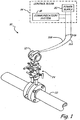
- FIG. 1 shows process control system 10 in which process transmitter 12 of the present invention is used.
- Process control system 10 includes process transmitter 12, control room 14 and control loop 16.
- Control room 14 includes communication system 18 and power supply 20.
- Process transmitter 12 is coupled with piping 22, in which a process fluid flows, through manifold 24.
- Process transmitter 12 includes a sensor and electronics for monitoring a process variable such as temperature, pressure, flow or level of the process fluid.
- Process transmitter 12 generates an electrical signal based on the sensed process variable.
- process transmitter 12 is a two-wire transmitter for operating on a 4-20 mA loop.
- control loop 16 includes first wire 16A and second wire 16B for supplying power to process transmitter 12 from power supply 20.
- Control loop 16 also permits process transmitter 12 to communicate with communication system 18.
- a 4 mA DC current provides sufficient energy for operating the sensor and transmitter circuitry of process transmitter 12 and a display for showing an output representing the sensed process variable.
- Process transmitter 12 transmits an output to communication system 18 over control loop 16 utilizing a 4 mA to 20 mA output signal generated by the transmitter circuitry of process transmitter 12.
- the 4-20 mA output signal is a function of the magnitude of the sensed process variable.
- process transmitter 12 communicates with control room 14 over a wireless network.
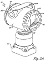
- FIG. 2A shows process transmitter 12 of the present invention having temperature responsive indicator 26 used as the local display.
- Process transmitter 12 comprises indicator 26, housing 28 and pressure flange 30.
- Housing 28, front cover 32 and rear cover 34 provide a structure for protecting the electronics and providing a field wiring terminal block to process transmitter 12.
- Front cover 32 has a glass window to allow viewing of indicator 26.
- Rear cover 34 is removable to allow access to a terminal block for connecting wires 16A and 16B of control loop 16 to the electronics of process transmitter 12.
- Housing 28 also includes conduit connections 36A and 36B that are used for feeding connecting wires 16A and 16B into housing 28.
- Pressure flange 30 is used to connect process transmitter 12 with manifold 24 and piping 22.
- the electronics of process transmitter 12 produce a 4-20 mA output signal as a function of a process variable, that is transmitted across control loop 16.
- the 4-20 mA signal is also used in conjunction with indicator 26 to provide a local, visual indication of the process variable magnitude.
- indicator 26 is typically configured, first end 38 indicates low pressure and a low output signal level, while second end 40 indicates high pressure and a high output signal level.
- FIG. 2B is a block diagram of one embodiment of process transmitter 12, which includes temperature responsive indicator 26, sensor 42 and transmitter circuitry 44 including signal processing circuitry 46 and interface 48.
- Sensor 42 produces a sensor signal proportional to the sensed pressure.
- Signal processing circuitry 46 receives the sensor signal and performs such conditioning functions as filtering the sensor signal and adjusting the sensor signal for temperature variations.
- Circuitry 46 produces a control signal that causes interface 48 to adjust loop current I L to a value between 4mA and 20mA that is representative of the sensed process variable.
- the loop current I L flows from control room 14 through wire 16A, through interface 48 and indicator 26 to wire 16B, and back to control room 14.
- FIG. 2C is a block diagram of another embodiment of process transmitter 12, which includes temperature responsive indicator 26, sensor 42 and transmitter circuitry 44 including signal processing circuitry 46 and interface 48.
- Sensor 42 produces a sensor signal proportional to the sensed pressure.
- Signal processing circuitry 46 receives the sensor signal and performs such conditioning functions as filtering the sensor signal and adjusting the sensor signal for temperature variations.
- Circuitry 46 produces a control signal that causes interface 48 to adjust loop current I L to a value between 4mA and 20mA that is representative of the sensed process variable.
- the loop current I L flows from control room 14 through wire 16A, through interface 48 and back to control room 14.
- a separate current I l signal is fed directly to indicator 26.
- This embodiment allows the indicator to be used with digital protocol devices such as Fieldbus.
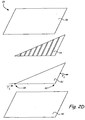
- FIG. 2D shows an exploded view of temperature responsive indicator 26 of FIG. 2A .
- Indicator 26 includes a conductive ink layer that is resistance heated by the 4-20 mA output signal, current I L (or current I l , as the case may be). The conductive ink layer thereby causes a thermochromic ink layer to change color in response to the amount of heat created in the conductive ink layer.
- indicator 26 provides a low-cost temperature responsive indicator that provides a visual representation of the magnitude of the sensed pressure.
- Indicator 26 is constructed in accordance with known principles for fabricating temperature responsive voltage indicators, some of which are disclosed in U.S. Patent Nos. 4,006,414 ; 4,702,564 ; 4,723,656 ; 5,188,231 and 5,607,790 .
- indicator 26 comprises first protective layer 50, conductive ink layer 52, Thermochromic ink layer 54 and second protective layer 56.
- First protective layer 50 provides a substrate on which to print Thermochromic ink layer 52 and conductive ink layer 54, while also protecting the ink layers.
- First protective layer 50 of indicator 26 may be made of any material suitable for printing on, such as paper or plastic materials.
- Conductive ink layer 52 allows current I L to be passed across indicator 26.
- Conductive ink layer 52 is printed onto, or otherwise adhered to, first protective layer 50 in the shape of a right-angle triangle, such that the surface area at first end 38 is smaller than the surface area at second end 40.
- Conductive ink layer 52 can be printed onto first protective layer 50 in any pattern in which the surface area of the conductive ink increases as it moves from one end to the other.
- the conductive ink is Electrodag ® 725A such as is commercially available from Acheson Colloids Company, Port Huron, MI, USA.
- Thermochromic ink layer 54 is printable on, or otherwise positioned adjacent to, conductive ink layer 52 and is shaped to match that of the conductive ink layer.
- Thermochromic ink layer 54 can have any shape that allows visual differentiation of the process variable level, such as a single bar shape or a triangular shape
- Thermochromic ink layer 54 also includes discrete bars to further indicate specific levels of the process variable. Bars at first end 38 of indicator 26 indicate low pressure. Bars at second end 40 of indicator 26 indicate high pressure. As current I L (or I l ) passes across indicator 26, the resistance of conductive layer 52 creates heat, thereby heating up Thermochromic ink layer 54.
- Thermochromic ink layer 54 alters its color at a threshold temperature.
- the threshold temperature is induced in thermochromic ink layer 54 by resistance heating of conductive ink layer 52 by current I L (or I l ). Because the thermochromic ink is affected by ambient temperature the indicator will not function optimally under all ambient temperature conditions. However, the use of this indicator is ideally suited for factory applications where the ambient temperature is controlled, and ambient influences are known.
- the threshold temperature is reached at some point along the temperature gradient in conductive ink layer 52 for each level of current, and moves from first end 38 to second end 40 as the current density of current increases. At the lowest level of current (e.g. 4 mA), the threshold temperature is reached in conductive ink layer 52 toward first end 38.
- the threshold temperature is reached in portions of conductive ink layer 52 occupying larger surface areas, toward second end 40.
- the highest level of current e.g. 20 mA
- thermochromic ink layer 54 is a first color, such as black.
- the thermochromic ink is formulated to change from the first color to a second color, such as green, at the threshold temperature.
- thermochromic ink layer 54 turns transparent at the threshold temperature.
- the thermochromic ink can be any temperature responsive ink, such as the class of ink disclosed in U.S. Patent No. 4,717,710 , or thermochromic inks such as ones distributed by Dow Corning Corporation, Midland, MI, USA or Chromatic Technologies, Inc., Colorado Springs, CO, USA.
- Second protective layer 56 covers and shields the ink layers while also allowing thermochromic ink layer 54 to be viewed.
- second protective layer 56 is a transparent plastic material.
- indicator 26 utilizes a liquid crystal based material rather than a thermochromic ink.
- Liquid crystal materials particularly cholesteric crystal materials, are clear at room temperature and change to a color at a threshold temperature.
- Liquid crystal based materials are sensitive to very small changes in temperature and are suited for use where gradual temperature changes will occur, but are somewhat more expensive. Therefore, they are particularly suitable for use as an indicator where somewhat more precision is necessary and somewhat higher costs are acceptable.
Landscapes
- Physics & Mathematics (AREA)
- General Physics & Mathematics (AREA)
- Engineering & Computer Science (AREA)
- Human Computer Interaction (AREA)
- Automation & Control Theory (AREA)
- Chemical & Material Sciences (AREA)
- Crystallography & Structural Chemistry (AREA)
- Arrangements For Transmission Of Measured Signals (AREA)
- Control Of Temperature (AREA)
Claims (15)
- Prozess-Transmitter (12) zum Messen einer Prozessvariablen, wobei der Prozess-Transmitter umfasst:eine Transmitterschaltung (44) zum Erzeugen eines eine abgefühlte Prozessvariable wiedergebenden elektrischen Ausgangs (IL, Il) und zum Weitergeben des variablen elektrischen Ausgangs über einen Prozessregelkreis (16);dadurch gekennzeichnet, dass der Prozess-Transmitter ferner eine temperaturempfindliche Anzeigeeinrichtung (26) umfasst, die auf in Abhängigkeit vom elektrischen Ausgang über den Prozessregelkreis erzeugte Wärme reagiert, um eine die Prozessvariable wiedergebende optische Anzeige bereitzustellen.
- Prozess-Transmitter nach Anspruch 1, wobei die optische Wiedergabe des elektrischen Ausgangs eine Größe der Prozessvariablen anzeigt.
- Prozess-Transmitter nach Anspruch 1, wobei die temperaturempfindliche Anzeigeeinrichtung eine Schicht aus leitfähiger Tinte (52) mit einer sich von einem ersten Ende (38) zu einem zweiten Ende (40) vergrößernden Oberfläche aufweist, wobei der elektrische Ausgang vom ersten zum zweiten Ende geleitet wird und dabei eine Widerstandserwärmung der Schicht aus leitfähiger Tinte verursacht.
- Prozess-Transmitter nach Anspruch 3, wobei die temperaturempfindliche Anzeigeeinrichtung eine an die Schicht aus leitfähiger Tinte angrenzende Schicht aus thermochromer Tinte (54) umfasst, wobei die Widerstandserwärmung der Schicht aus leitfähiger Tinte eine optische Änderung im Aussehen der Schicht aus thermochromer Tinte verursacht.
- Prozess-Transmitter nach Anspruch 3, wobei die temperaturempfindliche Anzeigeeinrichtung eine an die Schicht aus leitfähiger Tinte angrenzende Schicht aus Flüssigkristallmaterial umfasst, wobei die Widerstandserwärmung der Schicht aus leitfähiger Tinte eine optische Änderung im Aussehen der Schicht aus Flüssigkristallmaterial verursacht.
- Prozess-Transmitter nach Anspruch 1, wobei die Transmitterschaltung und die temperaturempfindliche Anzeigeeinrichtung derart in Reihe geschaltet sind, dass der elektrische Ausgang vor der Weitergabe an den Regelkreis durch die temperaturempfindliche Anzeigeeinrichtung geleitet wird.
- Prozess-Transmitter nach Anspruch 1, ferner umfassend:ein Gehäuse (28);einen Sensor (42), der im Gehäuse platziert ist und dafür konfiguriert ist, eine Schnittstelle mit einem Industrieprozess zu bilden, um eine Prozessvariable zu messen, die ausgewählt ist aus der Gruppe, bestehend aus Druck, Temperatur, Füllstand und Durchfluss eines Industrieprozessfluids, und ein variables Sensorsignal zu erzeugen, das von der gemessenen Prozessvariable abhängt;wobei die Transmitterschaltung im Gehäuse platziert und mit dem Sensor verbunden ist, um das variable Sensorsignal aufzubereiten und über den Prozessregelkreis als einen Kreisstrom weiterzugeben, wobei es sich bei dem Kreisstrom um den elektrischen Ausgang handelt; undwobei die temperaturempfindliche Anzeigeeinrichtung von einer Außenseite des Gehäuses aus sichtbar ist, wobei die Anzeigeeinrichtung umfasst:eine elektrisch leitfähige Schicht, die zwischen dem Prozessregelkreis und der Transmitter-Elektronik in Reihe geschaltet ist, um den Kreisstrom auf dem Weg zum Prozessregelkreis derart aufzunehmen, dass die elektrisch leitfähige Schicht aufgrund von Widerstandserwärmung eine Temperaturveränderung erfährt; und eine an die elektrisch leitfähige Schicht angrenzend platzierte temperaturempfindliche Schicht zum optischen Anzeigen einer Größe der gemessenen Prozessvariablen.
- Prozess-Transmitter nach Anspruch 7, wobei:die elektrisch leitfähige Schicht leitfähige Tinte (52) umfasst; unddie temperaturempfindliche Schicht Flüssigkristallmaterial umfasst.
- Prozess-Transmitter nach Anspruch 7, wobei:die elektrisch leitfähige Schicht leitfähige Tinte (52) umfasst; unddie temperaturempfindliche Schicht thermochrome Tinte (54) umfasst.
- Prozess-Transmitter nach Anspruch 7, wobei sich eine Oberfläche der elektrisch leitfähigen Schicht in einer Stromflussrichtung des Kreisstroms derart vergrößert, dass sich die Widerstandserwärmung der elektrisch leitfähigen Schicht in der Stromflussrichtung verringert.
- Prozess-Transmitter nach Anspruch 7, wobei sich eine Stromdichte des Kreisstroms in der Stromflussrichtung über die elektrisch leitfähige Schicht derart verringert, dass sich die Widerstandserwärmung der elektrisch leitfähigen Schicht in der Stromflussrichtung verringert.
- Prozess-Transmitter nach Anspruch 11, wobei die temperaturempfindliche Schicht dafür konfiguriert ist, sich in ihrem Aussehen optisch zu verändern, wenn die elektrisch leitfähige Schicht eine Schwellenstromdichte überschreitet.
- Prozess-Transmitter nach Anspruch 12, wobei sich die Stromdichte proportional zu einer Größe des variablen Sensorsignals ändert.
- Prozess-Transmitter nach Anspruch 13, wobei die temperaturempfindliche Schicht die Größe des variablen Sensorsignals bei der Schwellenstromdichte anzeigt.
- Prozess-Transmitter nach einem der Ansprüche 7 bis 14, wobei es sich bei dem Prozess-Transmitter um einen Industrieprozess-Transmitter handelt.
Applications Claiming Priority (2)
| Application Number | Priority Date | Filing Date | Title |
|---|---|---|---|
| US11/401,074 US7528737B2 (en) | 2006-04-10 | 2006-04-10 | Temperature responsive indicators for process control instruments |
| PCT/US2007/004407 WO2007126489A2 (en) | 2006-04-10 | 2007-02-20 | Temperature responsive indicators for process control instruments |
Publications (3)
| Publication Number | Publication Date |
|---|---|
| EP2011107A2 EP2011107A2 (de) | 2009-01-07 |
| EP2011107A4 EP2011107A4 (de) | 2015-04-29 |
| EP2011107B1 true EP2011107B1 (de) | 2017-08-30 |
Family
ID=38604329
Family Applications (1)
| Application Number | Title | Priority Date | Filing Date |
|---|---|---|---|
| EP07751182.2A Active EP2011107B1 (de) | 2006-04-10 | 2007-02-20 | Temperaturempfindliche indikatoren für prozessteuerinstrumente |
Country Status (4)
| Country | Link |
|---|---|
| US (1) | US7528737B2 (de) |
| EP (1) | EP2011107B1 (de) |
| JP (1) | JP5143126B2 (de) |
| WO (1) | WO2007126489A2 (de) |
Families Citing this family (32)
| Publication number | Priority date | Publication date | Assignee | Title |
|---|---|---|---|---|
| US7562811B2 (en) | 2007-01-18 | 2009-07-21 | Varcode Ltd. | System and method for improved quality management in a product logistic chain |
| US20080144699A1 (en) * | 2006-12-19 | 2008-06-19 | Honeywell International, Inc. | Method of sensing high surface temperatures in an aircraft |
| EP2156369B1 (de) | 2007-05-06 | 2015-09-02 | Varcode Ltd. | System und verfahren zur qualitätsverwaltung unter verwendung von strichcodeindikatoren |
| US8898036B2 (en) | 2007-08-06 | 2014-11-25 | Rosemount Inc. | Process variable transmitter with acceleration sensor |
| US8128283B2 (en) | 2007-09-28 | 2012-03-06 | Finisar Corporation | Temperature measurement apparatus for optoelectronic transceiver |
| WO2009063465A2 (en) | 2007-11-14 | 2009-05-22 | Varcode Ltd. | A system and method for quality management utilizing barcode indicators |
| US7757623B2 (en) * | 2007-12-20 | 2010-07-20 | Cooper Technologies Company | Explosion indicators for use in explosion-proof enclosures with critical equipment |
| US9494476B2 (en) | 2007-12-20 | 2016-11-15 | Cooper Technologies Company | Indicator device for an enclosure with sealing compound |
| US9111425B2 (en) * | 2007-12-20 | 2015-08-18 | Cooper Technologies Company | Indicating devices and associated methods |
| US7839281B2 (en) * | 2008-05-19 | 2010-11-23 | Cooper Technologies Company | Explosion indicator for explosion-proof enclosures |
| US11704526B2 (en) | 2008-06-10 | 2023-07-18 | Varcode Ltd. | Barcoded indicators for quality management |
| US8228206B2 (en) * | 2008-08-18 | 2012-07-24 | Cooper Technologies Company | Explosion indicator for explosion-proof enclosures |
| US7918134B2 (en) * | 2008-10-06 | 2011-04-05 | Rosemount Inc. | Thermal-based diagnostic system for process transmitter |
| US8387463B2 (en) * | 2008-10-06 | 2013-03-05 | Rosemount Inc. | Pressure-based diagnostic system for process transmitter |
| US20110048313A1 (en) * | 2009-09-03 | 2011-03-03 | General Electric Company | Indicating thermal dosage exposure of electric lamps |
| US9207670B2 (en) | 2011-03-21 | 2015-12-08 | Rosemount Inc. | Degrading sensor detection implemented within a transmitter |
| US20130014676A1 (en) | 2011-07-15 | 2013-01-17 | Airdex International, Inc. | Load bearing structure having antimicrobial properties |
| USD712765S1 (en) * | 2012-03-09 | 2014-09-09 | Honeywell International Inc. | Compact wired transmitter with external configuration features for hazardous locations |
| US9052240B2 (en) | 2012-06-29 | 2015-06-09 | Rosemount Inc. | Industrial process temperature transmitter with sensor stress diagnostics |
| US9602122B2 (en) | 2012-09-28 | 2017-03-21 | Rosemount Inc. | Process variable measurement noise diagnostic |
| US8807422B2 (en) | 2012-10-22 | 2014-08-19 | Varcode Ltd. | Tamper-proof quality management barcode indicators |
| USD709853S1 (en) * | 2013-04-24 | 2014-07-29 | Furukawa Unic Corporation | Industrial radio transmitter |
| USD696642S1 (en) * | 2013-07-01 | 2013-12-31 | Rosemount Inc. | Industrial process control transmitter puck |
| USD696222S1 (en) * | 2013-07-01 | 2013-12-24 | Rosemount Inc. | Process transmitter housing |
| JP6649472B2 (ja) | 2015-05-18 | 2020-02-19 | バーコード リミティド | 活性化可能な品質表示ラベルのための熱変色性インク証印 |
| US10697837B2 (en) | 2015-07-07 | 2020-06-30 | Varcode Ltd. | Electronic quality indicator |
| CN108139279B (zh) * | 2015-10-21 | 2020-07-03 | 株式会社日立制作所 | 温度检测体 |
| CA3035111C (en) * | 2016-09-30 | 2023-10-24 | Rosemount Inc. | Process pressure transmitter with polymer seal |
| CN107063492A (zh) * | 2017-04-20 | 2017-08-18 | 武汉大学 | 一种印刷型温度传感器及应用该温度传感器的疏散标志 |
| US10935441B2 (en) * | 2017-09-21 | 2021-03-02 | Wipro Limited | Wearable device to indicate hazardous conditions and a method thereof |
| JP2024505407A (ja) * | 2021-01-12 | 2024-02-06 | マイクロ モーション インコーポレイテッド | アクセス性が向上したインターフェース |
| DE102022108030A1 (de) | 2022-04-04 | 2023-10-05 | Vega Grieshaber Kg | Sensor mit autarker Temperaturüberwachung |
Family Cites Families (45)
| Publication number | Priority date | Publication date | Assignee | Title |
|---|---|---|---|---|
| US3617374A (en) * | 1969-04-14 | 1971-11-02 | Ncr Co | Display device |
| JPS516547B1 (de) * | 1969-06-05 | 1976-02-28 | ||
| US3827301A (en) * | 1972-09-18 | 1974-08-06 | Parker Research Robert | Fin cooled temperature sensor employing liquid crystals |
| US3936817A (en) | 1974-06-06 | 1976-02-03 | Sidney Levy | Thermoelectric display device |
| US4358955A (en) * | 1980-09-29 | 1982-11-16 | Technomadic Corporation | Liquid level gauge |
| JPS58110816U (ja) * | 1982-01-25 | 1983-07-28 | カルソニックカンセイ株式会社 | 表示装置 |
| US4717710A (en) * | 1985-01-17 | 1988-01-05 | Matsui Shikiso Chemical Co. Ltd. | Thermochromic composition |
| US4726661A (en) | 1985-04-15 | 1988-02-23 | Robert Parker | Flexible resistive heat battery tester and holder |
| GB2180964A (en) * | 1985-08-29 | 1987-04-08 | Johnson Matthey Plc | Indicator element |
| US4723656A (en) * | 1987-06-04 | 1988-02-09 | Duracell Inc. | Battery package with battery condition indicator means |
| US5058999A (en) * | 1987-07-13 | 1991-10-22 | Frederick Davis | Liquid crystal device having distinguishing means |
| US4919983A (en) * | 1988-04-04 | 1990-04-24 | Fremin Kit C | Thermochromatic infant feeding container |
| US5188231A (en) * | 1991-05-31 | 1993-02-23 | Duracell Inc. | Battery package with removable voltage indicator means |
| US5400610A (en) * | 1994-02-22 | 1995-03-28 | Ero Industries, Inc. | Portable insulated container with temperature indicator |
| US5583294A (en) * | 1994-08-22 | 1996-12-10 | The Foxboro Company | Differential pressure transmitter having an integral flame arresting body and overrange diaphragm |
| US5578390A (en) * | 1994-09-29 | 1996-11-26 | Duracell Inc. | Electrochemical cell label with integrated tester |
| US5499597A (en) * | 1994-11-01 | 1996-03-19 | Kronberg; James W. | Optical temperature indicator using thermochromic semiconductors |
| US5795070A (en) * | 1995-12-15 | 1998-08-18 | Geschwender; Robert C. | Thermometer |
| US5780746A (en) * | 1996-08-07 | 1998-07-14 | Fel-Pro Incorporated | Minimum thickness force sensor with temperature compensation |
| ES2189990T3 (es) * | 1996-12-20 | 2003-07-16 | Reckitt Benckiser France | Mejoras introducidas en envases. |
| US6121753A (en) * | 1997-01-23 | 2000-09-19 | Walker; Douglas W. | Apparatus and method for testing and indicating battery charge and functionality |
| US5813992A (en) * | 1997-05-20 | 1998-09-29 | Henwood; Peter S. W. | Single use indicator for stethoscopes |
| AUPO813297A0 (en) * | 1997-07-21 | 1997-08-14 | Premium Pharmaceuticals Pty Limited | Package for a suncream |
| US6426826B1 (en) * | 1997-11-23 | 2002-07-30 | Adact Ltd. | Display device |
| US6126313A (en) * | 1998-08-17 | 2000-10-03 | Schiller; Robert | Temperature responsive temperature/pressure display for a liquefied nitrous oxide container |
| US6158227A (en) * | 1998-10-29 | 2000-12-12 | Seeley; Eric E | Monitoring system for beverage chilling |
| CA2347866A1 (en) * | 1998-11-02 | 2000-05-11 | Russell J. Wilcox | Broadcast system for display devices made of electronic ink |
| US6483275B1 (en) * | 1999-04-23 | 2002-11-19 | The Board Of Trustees Of The Univesity Of Illinois | Consumer battery having a built-in indicator |
| US6984993B2 (en) * | 1999-04-28 | 2006-01-10 | Nexense Ltd. | Method and apparatus for making high-precision measurements |
| CA2273585A1 (en) * | 1999-05-28 | 2000-11-28 | Canpolar East Inc. | Sensors for detecting changes in temperature, ph, chemical conditions, biological conditions, radiation, electrical field and pressure |
| US6318020B1 (en) * | 1999-07-26 | 2001-11-20 | Larry Mefferd | Thermochromic fishing lure and method of making same |
| US6731221B1 (en) * | 1999-12-20 | 2004-05-04 | Intel Corporation | Electrically modifiable product labeling |
| US6452493B1 (en) * | 2000-01-19 | 2002-09-17 | Sor, Inc. | Process control instrument with multiple functions |
| US6544925B1 (en) * | 2000-03-02 | 2003-04-08 | Lifelines Technology, Inc. | Activatable time-temperature indicator system |
| US6519835B1 (en) * | 2000-08-18 | 2003-02-18 | Watlow Polymer Technologies | Method of formable thermoplastic laminate heated element assembly |
| US7112766B2 (en) * | 2001-02-21 | 2006-09-26 | Lerner William S | Enhanced visibility heat alert safety device for hot surfaces |
| US6450024B1 (en) * | 2001-03-07 | 2002-09-17 | Delta M Corporation | Flow sensing device |
| US6694912B2 (en) * | 2001-06-27 | 2004-02-24 | Blyth, Inc. | Thermochromic ink safety label for chafing fuel cans and methods of making the same |
| US6522249B1 (en) * | 2001-08-30 | 2003-02-18 | United Electric Controls, Co. | Two wire output/power mechanism for remote devices |
| US6761066B2 (en) * | 2002-02-20 | 2004-07-13 | Joseph Rait | Level indicator |
| US6880396B2 (en) * | 2002-02-20 | 2005-04-19 | Joseph Rait | Level indicator having thermochromic leucodye inks |
| US7035773B2 (en) * | 2002-03-06 | 2006-04-25 | Fisher-Rosemount Systems, Inc. | Appendable system and devices for data acquisition, analysis and control |
| DE10315106A1 (de) * | 2003-04-02 | 2004-10-14 | Endress + Hauser Flowtec Ag, Reinach | Vorrichtung zur Überwachung eines Meßumformers eines Feldgeräts |
| US7557433B2 (en) * | 2004-10-25 | 2009-07-07 | Mccain Joseph H | Microelectronic device with integrated energy source |
| US9612137B2 (en) * | 2006-05-02 | 2017-04-04 | Rosemount Inc. | Instrument housing with embedded liquid crystal display within plastic layer |
-
2006
- 2006-04-10 US US11/401,074 patent/US7528737B2/en active Active
-
2007
- 2007-02-20 EP EP07751182.2A patent/EP2011107B1/de active Active
- 2007-02-20 WO PCT/US2007/004407 patent/WO2007126489A2/en not_active Ceased
- 2007-02-20 JP JP2009505360A patent/JP5143126B2/ja not_active Expired - Fee Related
Non-Patent Citations (1)
| Title |
|---|
| None * |
Also Published As
| Publication number | Publication date |
|---|---|
| US7528737B2 (en) | 2009-05-05 |
| EP2011107A4 (de) | 2015-04-29 |
| US20070241916A1 (en) | 2007-10-18 |
| JP5143126B2 (ja) | 2013-02-13 |
| WO2007126489A3 (en) | 2008-06-05 |
| EP2011107A2 (de) | 2009-01-07 |
| JP2009533678A (ja) | 2009-09-17 |
| WO2007126489A2 (en) | 2007-11-08 |
Similar Documents
| Publication | Publication Date | Title |
|---|---|---|
| EP2011107B1 (de) | Temperaturempfindliche indikatoren für prozessteuerinstrumente | |
| JP4987977B2 (ja) | 複数の参照圧力センサを有する圧力トランスミッタ | |
| CN101495846B (zh) | 冗余机械和电子遥控密封系统 | |
| JP5340141B2 (ja) | プラスチック層内部に液晶ディスプレイが埋め込まれた装置筐体 | |
| EP2577245B1 (de) | Prozessvariabler sender mit erkennung der thermoelemntpolarität | |
| CN106643814A (zh) | 温度平均现场设备补偿 | |
| JP2012524935A (ja) | 産業プロセス制御システム用計測制御装置 | |
| US10692421B2 (en) | Additional module for a processing and/or automation field device | |
| EP3314211B1 (de) | Prozessvariablenmessung und lokale anzeige mit mehreren bereichen | |
| US20090122831A1 (en) | Intelligent flow/temperature measuring device | |
| US20060162419A1 (en) | Measuring device with plausibility check | |
| US12066309B2 (en) | Variable area flowmeter, system comprising a variable area flowmeter and an external control unit, and method for operating a variable area flowmeter | |
| CN201072349Y (zh) | 流量温度检测仪 | |
| EP1866768B1 (de) | Benutzerbetrachtbare relative diagnostikausgabe | |
| KR102616884B1 (ko) | 무전원 디지털 지시계 | |
| KR102616885B1 (ko) | 무전원 디지털 지시계 | |
| EP1657529B1 (de) | Digitale Anzeige | |
| JP4988244B2 (ja) | 測定装置 | |
| KR102208088B1 (ko) | 기류 측정 장치 | |
| JP2010160102A (ja) | センサデータ伝送システム | |
| WO2007149499A2 (en) | Configurable indicating device and method for monitoring and control in fluid systems | |
| CN112179398A (zh) | 测量装置的人机介面 | |
| MARKS et al. | 3.6 Transmitters—Electronic | |
| VAMSIDHAR | SCADA IMPLEMENTATION FOR A REMOTE PROCESS MONITORING AND CONTROL | |
| JP2009115812A (ja) | 流量計 |
Legal Events
| Date | Code | Title | Description |
|---|---|---|---|
| PUAI | Public reference made under article 153(3) epc to a published international application that has entered the european phase |
Free format text: ORIGINAL CODE: 0009012 |
|
| 17P | Request for examination filed |
Effective date: 20081110 |
|
| AK | Designated contracting states |
Kind code of ref document: A2 Designated state(s): AT BE BG CH CY CZ DE DK EE ES FI FR GB GR HU IE IS IT LI LT LU LV MC NL PL PT RO SE SI SK TR |
|
| AX | Request for extension of the european patent |
Extension state: AL BA HR MK RS |
|
| DAX | Request for extension of the european patent (deleted) | ||
| RBV | Designated contracting states (corrected) |
Designated state(s): CH DE LI |
|
| REG | Reference to a national code |
Ref country code: DE Ref legal event code: R079 Ref document number: 602007052186 Country of ref document: DE Free format text: PREVIOUS MAIN CLASS: G09G0005000000 Ipc: G01K0011120000 |
|
| A4 | Supplementary search report drawn up and despatched |
Effective date: 20150331 |
|
| RIC1 | Information provided on ipc code assigned before grant |
Ipc: G01K 3/00 20060101ALI20150325BHEP Ipc: G09G 5/00 20060101ALI20150325BHEP Ipc: G01K 11/12 20060101AFI20150325BHEP Ipc: G01K 11/16 20060101ALI20150325BHEP Ipc: G08B 1/08 20060101ALI20150325BHEP |
|
| 17Q | First examination report despatched |
Effective date: 20160229 |
|
| GRAP | Despatch of communication of intention to grant a patent |
Free format text: ORIGINAL CODE: EPIDOSNIGR1 |
|
| STAA | Information on the status of an ep patent application or granted ep patent |
Free format text: STATUS: GRANT OF PATENT IS INTENDED |
|
| INTG | Intention to grant announced |
Effective date: 20170222 |
|
| GRAS | Grant fee paid |
Free format text: ORIGINAL CODE: EPIDOSNIGR3 |
|
| GRAJ | Information related to disapproval of communication of intention to grant by the applicant or resumption of examination proceedings by the epo deleted |
Free format text: ORIGINAL CODE: EPIDOSDIGR1 |
|
| GRAL | Information related to payment of fee for publishing/printing deleted |
Free format text: ORIGINAL CODE: EPIDOSDIGR3 |
|
| STAA | Information on the status of an ep patent application or granted ep patent |
Free format text: STATUS: EXAMINATION IS IN PROGRESS |
|
| GRAR | Information related to intention to grant a patent recorded |
Free format text: ORIGINAL CODE: EPIDOSNIGR71 |
|
| STAA | Information on the status of an ep patent application or granted ep patent |
Free format text: STATUS: GRANT OF PATENT IS INTENDED |
|
| GRAA | (expected) grant |
Free format text: ORIGINAL CODE: 0009210 |
|
| STAA | Information on the status of an ep patent application or granted ep patent |
Free format text: STATUS: THE PATENT HAS BEEN GRANTED |
|
| INTC | Intention to grant announced (deleted) | ||
| AK | Designated contracting states |
Kind code of ref document: B1 Designated state(s): CH DE LI |
|
| INTG | Intention to grant announced |
Effective date: 20170725 |
|
| REG | Reference to a national code |
Ref country code: CH Ref legal event code: EP |
|
| REG | Reference to a national code |
Ref country code: DE Ref legal event code: R096 Ref document number: 602007052186 Country of ref document: DE |
|
| REG | Reference to a national code |
Ref country code: DE Ref legal event code: R097 Ref document number: 602007052186 Country of ref document: DE |
|
| PLBE | No opposition filed within time limit |
Free format text: ORIGINAL CODE: 0009261 |
|
| STAA | Information on the status of an ep patent application or granted ep patent |
Free format text: STATUS: NO OPPOSITION FILED WITHIN TIME LIMIT |
|
| 26N | No opposition filed |
Effective date: 20180531 |
|
| PGFP | Annual fee paid to national office [announced via postgrant information from national office to epo] |
Ref country code: CH Payment date: 20190304 Year of fee payment: 13 |
|
| REG | Reference to a national code |
Ref country code: CH Ref legal event code: PL |
|
| PG25 | Lapsed in a contracting state [announced via postgrant information from national office to epo] |
Ref country code: CH Free format text: LAPSE BECAUSE OF NON-PAYMENT OF DUE FEES Effective date: 20200229 Ref country code: LI Free format text: LAPSE BECAUSE OF NON-PAYMENT OF DUE FEES Effective date: 20200229 |
|
| PGFP | Annual fee paid to national office [announced via postgrant information from national office to epo] |
Ref country code: DE Payment date: 20250122 Year of fee payment: 19 |