EP2010810B1 - Dichtungsring - Google Patents
Dichtungsring Download PDFInfo
- Publication number
- EP2010810B1 EP2010810B1 EP07748028A EP07748028A EP2010810B1 EP 2010810 B1 EP2010810 B1 EP 2010810B1 EP 07748028 A EP07748028 A EP 07748028A EP 07748028 A EP07748028 A EP 07748028A EP 2010810 B1 EP2010810 B1 EP 2010810B1
- Authority
- EP
- European Patent Office
- Prior art keywords
- sealing
- sealing ring
- groove
- socket end
- holding element
- Prior art date
- Legal status (The legal status is an assumption and is not a legal conclusion. Google has not performed a legal analysis and makes no representation as to the accuracy of the status listed.)
- Not-in-force
Links
Images


Classifications
-
- F—MECHANICAL ENGINEERING; LIGHTING; HEATING; WEAPONS; BLASTING
- F16—ENGINEERING ELEMENTS AND UNITS; GENERAL MEASURES FOR PRODUCING AND MAINTAINING EFFECTIVE FUNCTIONING OF MACHINES OR INSTALLATIONS; THERMAL INSULATION IN GENERAL
- F16L—PIPES; JOINTS OR FITTINGS FOR PIPES; SUPPORTS FOR PIPES, CABLES OR PROTECTIVE TUBING; MEANS FOR THERMAL INSULATION IN GENERAL
- F16L21/00—Joints with sleeve or socket
- F16L21/02—Joints with sleeve or socket with elastic sealing rings between pipe and sleeve or between pipe and socket, e.g. with rolling or other prefabricated profiled rings
- F16L21/03—Joints with sleeve or socket with elastic sealing rings between pipe and sleeve or between pipe and socket, e.g. with rolling or other prefabricated profiled rings placed in the socket before connection
-
- F—MECHANICAL ENGINEERING; LIGHTING; HEATING; WEAPONS; BLASTING
- F16—ENGINEERING ELEMENTS AND UNITS; GENERAL MEASURES FOR PRODUCING AND MAINTAINING EFFECTIVE FUNCTIONING OF MACHINES OR INSTALLATIONS; THERMAL INSULATION IN GENERAL
- F16L—PIPES; JOINTS OR FITTINGS FOR PIPES; SUPPORTS FOR PIPES, CABLES OR PROTECTIVE TUBING; MEANS FOR THERMAL INSULATION IN GENERAL
- F16L17/00—Joints with packing adapted to sealing by fluid pressure
- F16L17/02—Joints with packing adapted to sealing by fluid pressure with sealing rings arranged between outer surface of pipe and inner surface of sleeve or socket
- F16L17/03—Joints with packing adapted to sealing by fluid pressure with sealing rings arranged between outer surface of pipe and inner surface of sleeve or socket having annular axial lips
- F16L17/035—Joints with packing adapted to sealing by fluid pressure with sealing rings arranged between outer surface of pipe and inner surface of sleeve or socket having annular axial lips the sealing rings having two lips parallel to each other
-
- F—MECHANICAL ENGINEERING; LIGHTING; HEATING; WEAPONS; BLASTING
- F16—ENGINEERING ELEMENTS AND UNITS; GENERAL MEASURES FOR PRODUCING AND MAINTAINING EFFECTIVE FUNCTIONING OF MACHINES OR INSTALLATIONS; THERMAL INSULATION IN GENERAL
- F16L—PIPES; JOINTS OR FITTINGS FOR PIPES; SUPPORTS FOR PIPES, CABLES OR PROTECTIVE TUBING; MEANS FOR THERMAL INSULATION IN GENERAL
- F16L21/00—Joints with sleeve or socket
- F16L21/02—Joints with sleeve or socket with elastic sealing rings between pipe and sleeve or between pipe and socket, e.g. with rolling or other prefabricated profiled rings
- F16L21/035—Joints with sleeve or socket with elastic sealing rings between pipe and sleeve or between pipe and socket, e.g. with rolling or other prefabricated profiled rings placed around the spigot end before connection
Definitions
- the present invention relates to a sealing ring for sealing an annular gap between an inner face of a socket end of a first tube element and an outer face of a spigot end of a second tube element, the socket end having a circumferential inside groove for receiving the sealing ring, which groove at its bottom has a radius, which due to the manufacturing tolerances of the first tube element is between a minimum value R'min and a maximum value R'max, and the spigot end being concentrically insertable into the socket end to form said gap during compression of the sealing ring, said gap having a radial gap width, which due to the manufacturing tolerances of the two tube elements is between a minimum value Tmin and a maximum value Tmax, which sealing ring has an annular sealing element with a first sealing part for sealing against the inner face of the socket end in the bottom of the circumferential groove and a second sealing part for sealing against the outer face of the spigot end and further has an annular holding element which is connected to the sealing element and which is more rigid than the sealing element but so
- a sealing ring of this type is elastically deformed when being inserted into the socket end so as to be expanded again when reaching the groove, in which it is then retained by the holding element, which is more rigid than the sealing element.
- FIGs 1-3 are partial longitudinal sections and schematically illustrate the prior-art sealing ring arranged in an inside groove in a socket end, in which a spigot end is inserted, the sealing ring being shown in its state of rest.
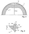
- Fig. 4 is a schematic cross-sectional view and illustrates the socket end with the sealing ring inserted, the sealing ring being shown in a compressed and deformed state for the case illustrated in Fig. 3 .
- Figs 1-4 illustrate most schematically a portion of a socket end 1 of a first tube element and a spigot end 2 of a second tube element, the spigot end being concentrically inserted in the socket end 1 in the direction of arrow P.
- the socket end 1 has a circumferential inside groove 3 for receiving a prior-art sealing ring 4 for sealing the annular gap 5 between the socket end 1 and the spigot end 2.
- the gap width of the gap 5 may vary.
- the variation of the gap width may be considerable when the tube elements are made of, for instance, cast iron, while it is significantly smaller when the tube elements are made of plastic. It should be noted that, for reasons of clarity, the variation of the gap width is considerably exaggerated in Figs 1-3 .
- Fig. 1 shows the nominal gap width T, which is obtained when the inner radius of the socket end 1 equals the nominal inner radius R and the outer radius of the socket end 2 equals the nominal outer radius r.
- the radius of the groove 3 at the bottom of the groove is R'.
- Fig. 2 shows the maximum gap width Tmax which can exist with existing manufacturing tolerances, the inner radius of the socket end 1 having its maximum value Rmax and the outer radius of the spigot end 2 having its minimum value rmin.
- the radius of the groove 3 at the bottom of the groove has its maximum value R'max.
- Fig. 3 shows the minimum gap width Tmin which can exist with existing manufacturing tolerances, the inner radius of the socket end 1 having its minimum value Rmin and the outer radius of the spigot end 2 having its maximum value rmax.
- the radius of the groove 3 at the bottom of the groove has its minimum value R'min.
- the prior-art sealing ring 4 comprises an annular sealing element 6 of rubber material with a first sealing part 7 for sealing against the inner face of the socket end 1 in the groove 3 and a second sealing part 8 for sealing against the outer face of the spigot end 2.
- the first sealing part 7 has an outer shape which is adjusted to the shape of the groove 3, while the second sealing part 8 has the shape of a sealing lip, which is slightly inclined in the direction P along which the spigot end 2 is inserted into the socket end 1.
- the prior-art sealing ring 4 also comprises an annular holding element 9 which is connected to the sealing element 6 and positioned at the side of the sealing element 6 from which the spigot end 2 is inserted into the socket end 1, and which is arranged to abut against one groove wall of the groove 3.
- the holding element 9 is made of a plastic material, which is more rigid than the rubber material of which the sealing element 6 is made, and is so elastically deformable as to allow insertion of the sealing ring 4 into the groove 3.
- the holding element 9 retains the sealing ring 4 in the groove 3.
- the outer radius of the first sealing part 7 is insignificantly greater than R'max (see Fig. 2 ), which allows it to seal against the bottom of the groove 3 in the case shown in Fig. 2 with a maximum gap width Tmax.
- the first sealing part 7 is thus slightly compressed when the sealing ring 4 is inserted in the groove 3.
- the first sealing part 7 is further compressed (since R' ⁇ R'max) when the sealing ring 4 is inserted in the groove 3.
- the object of the present invention is therefore to provide a sealing ring, which eliminates the above-described drawback and establishes a perfect seal against the inner face of a socket end also when there are great manufacturing tolerances, such as for tube elements of cast iron, in which case the sealing ring is retained in a safe manner in the groove of the socket end even when it is subjected to high pressure.
- a sealing ring which is of the type stated by way of introduction and characterised in that the first sealing part has a neck portion, which is positioned radially outside the holding element and which supports a radially outer head portion, which is positioned radially outside the holding element and whose outer radius is slightly greater than R'max, the first sealing part being, at the level of the neck portion, bendable in the axial direction along which the spigot end is to be inserted into the socket end, and the cross-section of the annular holding element has a radial extent which is greater than 2 x Tmax.
- the radially outer face of the head portion has, over the major part of its axial extent, a diameter increasing in the direction of insertion of the spigot end.
- the holding element is suitably positioned at the side of the sealing element from which the spigot end is to be inserted into the socket end.
- the sealing ring comprises a third sealing part which is axially opposite the holding element and adapted to seal against the inner face of the socket end, said third sealing part and the holding element being each arranged to abut against one of the axially spaced-apart groove walls of the groove.
- the sealing element is suitably made of a rubber material and the holding element is suitably made of a plastic material.
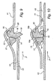
- Figs 6-8 schematically illustrate a portion of a socket end 11 of a first tube element and a spigot end 12 of a second tube element, the spigot end being inserted into the socket end 11 in the direction of arrow P.
- the socket end 11 has a circumferential inside groove 13 for receiving a sealing ring 14 according to the invention for sealing the annular gap 15 between the socket end 11 and the spigot end 12.
- the gap width of the gap 15 may vary.
- the variation of the gap width may be considerable when the tube elements, like in this case, are made of cast iron, while it is significantly smaller when the tube elements are made of, for instance, plastic.
- Figs 6-8 like Figs 1-3 illustrate the variation of the gap width in a considerably exaggerated manner.
- Fig. 6 illustrates, like Fig. 1 , the nominal gap width T, which is obtained when the inner radius of the socket end 11 equals the nominal inner radius R and the outer radius of the spigot end 12 equals the nominal outer radius r.
- the radius of the groove 13 at the bottom of the groove is R'.
- Fig. 7 illustrates, like Fig. 2 , the maximum gap width Tmax which can exist with existing manufacturing tolerances, the inner radius of the spigot end 11 having its maximum value Rmax and the outer radius of the spigot end 12 having its minimum value rmin.
- the radius of the groove 13 at the bottom of the groove has its maximum value R'max.
- Fig. 8 shows, like Fig. 3 , the minimum gap width Tmin which can exist with existing manufacturing tolerances, the inner radius of the socket end 11 having its minimum value Rmin and the outer radius of the spigot end 12 having its maximum value rmax.
- the radius of the groove 13 at the bottom of the groove has its minimum value R'min.
- the sealing ring 14 comprises an annular sealing element 16 of rubber material and an annular holding element 17 which is connected to the sealing element and made of a plastic material, such as propene plastic, which is harder and more rigid than the rubber material of which the sealing element 16 is made.
- the holding element 17 is positioned at the side of the sealing element 16 from which the spigot end 12 is inserted in the direction P into the socket end 11.
- the annular holding element 17 is so elastically deformable as to allow insertion of the sealing ring 14 into the groove 13.
- the sealing element 16 has a first sealing part 18 for sealing against the bottom of the circumferential groove 13 and a second sealing part 19 for sealing against the outer face of the spigot end 12 (see Fig. 10 ), which second sealing part 19 has the shape of a sealing lip, which is slightly inclined in the direction P along which the spigot end 12 is inserted into the socket end 11.
- the sealing element 16 also comprises a third sealing part 20 arranged axially opposite the holding element 17 and adapted to seal against the other wall of the groove 13 (see Fig. 10 ), which third sealing element 20 has the shape of a sealing lip oriented substantially in the direction of insertion P of the spigot end 12.
- the first sealing part 18, which is oriented substantially radially outwards, has a neck portion 18a, which supports a radially outer head portion 18b, which is positioned radially outside the holding element 17 and whose outer radius is somewhat greater than R'max (see Fig. 7 ).
- the radially outer face of the head portion 18b has, over the major part of its axial extent, a radius increasing in the direction of insertion P of the spigot end 12. This radius increases to a radius, which equals said outer radius of the head portion 18b, that is the greatest radius seen over the axial extent of the head portion 18b.
- the first sealing part 18 is bendable in the direction of insertion P of the spigot end 12 into the space that exists between the first sealing part 18 and the third sealing part 20.
- the sealing ring 14 will not be crumpled up in the way shown in Fig. 4 but retains its circular shape and establishes a circumferential seal against the inner face of the socket end 12 even in the case when the radius of the groove 13 takes its minimum value R'min within the manufacturing tolerances.
- Fig. 10 illustrates by arrows the inner pressure prevailing in the piping (for instance a high-pressure system for drinking water) in which the tube elements provided with the socket end 11 and the spigot end 12 are included.
- the annular sealing element 16 of the sealing ring 14 is designed so that the interior pressure forces the sealing lips 19 and 20 into abutment against the outer face of the spigot end 12 and the wall of the groove 13, respectively, and thus "reinforces" the seal.
- first sealing part 18 with a neck portion 18a and a head portion 18b allows the sealing ring 14 to remain in sealing abutment against the bottom of the groove 13 and the outer face of the spigot end 12 also when a relatively high exterior pressure prevails in the gap 15 (to the left in Fig. 10 ) and the radius of the bottom of the groove is great.
- the holding element 17 has a cross-sectional shape whose radial extent A is greater than 2 x Tmax.
Landscapes
- Engineering & Computer Science (AREA)
- General Engineering & Computer Science (AREA)
- Mechanical Engineering (AREA)
- Physics & Mathematics (AREA)
- Fluid Mechanics (AREA)
- Joints With Sleeves (AREA)
- Sealing Devices (AREA)
- Glass Compositions (AREA)
- Materials For Medical Uses (AREA)
- Gasket Seals (AREA)
Claims (5)
- Dichtungsring zum Abdichten eines ringförmigen Spalts (15) zwischen einer inneren Fläche eines Steckmuffenendes (11) eines ersten Rohrelements und einer äußeren Fläche eines Stutzenendes (12) eines zweiten Rohrelements, wobei das Steckmuffenende (11) eine innenseitige Umfangsnut (13) zur Aufnahme des Dichtungsrings (14) hat, wobei die Nut an ihrem Boden einen Radius aufweist, welcher auf Grund der Herstellungstoleranzen des ersten Rohrelements zwischen einem minimalen Wert R'min und einem maximalen Wert R'max liegt, und das Stutzenende (12) konzentrisch in das Steckmuffenende (11) einschiebbar ist, um den Spalt (15) während des Zusammendrückens des Dichtungsrings (14) aufzubilden, wobei der Spalt eine radiale Spaltenbreite aufweist, welche auf Grund der Herstellungstoleranzen der zwei Rohrelemente zwischen einem minimalen Wert Tmin und einem maximalen Wert Tmax liegt, wobei der Dichtungsring (14) ein ringförmiges Dichtungselement (16) mit einem ersten Dichtungsteil (18) zum Abdichten gegen die innere Fläche des Steckmuffenendes (11) im Boden der Umfangsnut (13) und einen zweiten Dichtungsteil (19) zum Abdichten gegen die äußere Fläche des Stutzenendes (12) aufweist und des Weiteren ein ringförmiges Halteelement (17) besitzt, welches mit dem Dichtungselement (16) verbunden ist und welches steifer ist als das Dichtungselement (16), aber so elastisch verformbar, um das Einschieben des Dichtungsrings (14) in die Nut (13) zu gestatten,
gekennzeichnet dadurch, dass
der erste Dichtungsteil (18) einen Halsabschnitt (18a) aufweist, welcher radial außerhalb des Halteelements (17) positioniert ist und welcher einen radial äußeren Kopfabschnitt (18b) trägt, welcher radial außerhalb des Halteelements (17) positioniert ist und dessen äußerer Radius etwas größer als R'max ist, wobei der erste Dichtungsteil (18) auf dem Niveau des Halsabschnitts (18a) biegbar in der axialen Richtung (P) ist, entlang welcher das Stutzenende (12) in das Steckmuffenende (11) eingeschoben werden soll, und wobei der Querschnitt des ringförmigen Halteelements (17) ein radiales Ausmaß (A) aufweist, welches größer ist als 2 x Tmax. - Dichtungsring nach Anspruch 1, bei welchem die radial äußere Fläche des Kopfabschnitts (18b) über den größeren Teil seines axialen Ausmaβes einen Durchmesser aufweist, welcher in die Einschubrichtung (P) des Stutzenendes (12) zunimmt.
- Dichtungsring nach Anspruch 1 oder 2, bei welchem das Halteelement (17) an der Seite des Dichtungselements (16) positioniert ist, von welchem aus das Stutzenende (12) in das Steckmuffenende (11) eingeschoben werden soll.
- Dichtungsring nach Anspruch 3, welcher einen dritten Dichtungsteil (20) umfasst, der axial gegenüber dem Halteelement (17) liegt und so ausgelegt ist, um gegen die innere Fläche des Steckmuffenendes (11) abzudichten, wobei der dritte Dichtungsteil (20) und das Halteelement (17) jeweils so angeordnet sind, um gegen eine der axial beabstandeten Nutwände der Nut (13) zu stoßen.
- Dichtungsring nach jedem beliebigen der Ansprüche 1-4, bei welchem das Dichtungselement (16) aus einem Gummimaterial hergestellt ist und das Halteelement (17) aus einem Kunststoffmaterial hergestellt ist.
Priority Applications (1)
| Application Number | Priority Date | Filing Date | Title |
|---|---|---|---|
| PL07748028T PL2010810T3 (pl) | 2006-04-21 | 2007-04-18 | Pierścień uszczelniający |
Applications Claiming Priority (2)
| Application Number | Priority Date | Filing Date | Title |
|---|---|---|---|
| SE0600872A SE528639C2 (sv) | 2006-04-21 | 2006-04-21 | Tätningsring |
| PCT/SE2007/000363 WO2007123459A1 (en) | 2006-04-21 | 2007-04-18 | Sealing ring |
Publications (2)
| Publication Number | Publication Date |
|---|---|
| EP2010810A1 EP2010810A1 (de) | 2009-01-07 |
| EP2010810B1 true EP2010810B1 (de) | 2011-01-19 |
Family
ID=37596404
Family Applications (1)
| Application Number | Title | Priority Date | Filing Date |
|---|---|---|---|
| EP07748028A Not-in-force EP2010810B1 (de) | 2006-04-21 | 2007-04-18 | Dichtungsring |
Country Status (10)
| Country | Link |
|---|---|
| US (1) | US20090146419A1 (de) |
| EP (1) | EP2010810B1 (de) |
| AT (1) | ATE496250T1 (de) |
| AU (1) | AU2007241584B2 (de) |
| DE (1) | DE602007012070D1 (de) |
| NZ (1) | NZ571832A (de) |
| PL (1) | PL2010810T3 (de) |
| SE (1) | SE528639C2 (de) |
| WO (1) | WO2007123459A1 (de) |
| ZA (1) | ZA200807994B (de) |
Families Citing this family (6)
| Publication number | Priority date | Publication date | Assignee | Title |
|---|---|---|---|---|
| EP2609357A4 (de) * | 2010-08-24 | 2018-02-21 | Mueller International, LLC | Dichtung für ein selbsthaltendes kugellager einer parabolischen rampe |
| US9617822B2 (en) | 2013-12-03 | 2017-04-11 | Baker Hughes Incorporated | Compliant seal for irregular casing |
| AT14083U1 (de) | 2014-03-03 | 2015-04-15 | Henn Gmbh & Co Kg | Dichtung |
| DE102017107395A1 (de) * | 2017-04-06 | 2018-10-11 | Trelleborg Pipe Seals Lelystad BV | Rohrdichtung |
| WO2019076454A1 (en) * | 2017-10-18 | 2019-04-25 | Trelleborg Pipe Seals Lelystad B.V. | PIPE JOINT AND PIPE ASSEMBLY |
| CN110131500A (zh) * | 2019-05-18 | 2019-08-16 | 江苏狼博管道制造有限公司 | 一种承插胶圈密封硬锁止防松脱接口 |
Family Cites Families (19)
| Publication number | Priority date | Publication date | Assignee | Title |
|---|---|---|---|---|
| US3520541A (en) * | 1969-01-31 | 1970-07-14 | Amir Rohani | Gasketed pipe |
| US3684317A (en) * | 1970-04-20 | 1972-08-15 | Johns Manville | Pipe joint |
| US3856315A (en) * | 1973-01-02 | 1974-12-24 | P Stansbury | Bell and spigot pvc pipe joint |
| DE2726959A1 (de) * | 1977-06-15 | 1979-01-18 | Arlt Christian | Dichteinsatz zum dichten verbinden von zwei rohren |
| US4637618A (en) * | 1984-07-13 | 1987-01-20 | Vassallo Research & Development Corporation | Composite gasket and fitting including same |
| US4693483A (en) * | 1984-07-13 | 1987-09-15 | Vassallo Research & Development Corporation | Composite gasket and fitting including same |
| US4602793A (en) * | 1984-10-09 | 1986-07-29 | Polymer/Raymond Industries | Gasket with encapsulated locking ring |
| US4826028A (en) * | 1985-03-18 | 1989-05-02 | Vassallo Research & Development Corp. | Gasket seating ring |
| SE463664B (sv) * | 1986-04-17 | 1991-01-07 | Forsheda Ab | Formnings- och taetningsring |
| US4834398A (en) * | 1987-08-31 | 1989-05-30 | S & B Technical Products, Inc. | Pipe gasket |
| SE8800348L (sv) * | 1988-02-03 | 1989-08-04 | Forsheda Ab | Taetningsring och verktyg foer framstaellning daerav |
| US5197768B1 (en) * | 1991-10-10 | 1995-04-04 | American Cast Iron Pipe Co | Restrained joint having elastomer-backed locking segments |
| US5213339A (en) * | 1992-02-13 | 1993-05-25 | Reeves Rubber, Inc. | Pipe joint gasket |
| SE505267C2 (sv) * | 1992-03-10 | 1997-07-28 | Forsheda Ab | Sätt att framställa åtminstone två olika slag av tätningsringar och tätningselement för användning vid genomförande av sättet |
| US6142484A (en) * | 1999-04-15 | 2000-11-07 | Vassallo Research & Development Corporation | Composite multi-pressure gasket |
| GB9927785D0 (en) * | 1999-11-24 | 2000-01-26 | Forsheda Ab | Seal |
| US7158034B2 (en) * | 2004-01-12 | 2007-01-02 | Corbett Jr Bradford G | Pipe gasket manufacturing and identification method with RFID tracking |
| PL1619435T3 (pl) * | 2004-07-20 | 2009-08-31 | Bode Gmbh | Pierścień uszczelniający do wtykowych połączeń kielichowych |
| USD557386S1 (en) * | 2006-05-30 | 2007-12-11 | S & B Technical Products, Inc. | Pipe gasket |
-
2006
- 2006-04-21 SE SE0600872A patent/SE528639C2/sv unknown
-
2007
- 2007-04-18 NZ NZ571832A patent/NZ571832A/en unknown
- 2007-04-18 DE DE602007012070T patent/DE602007012070D1/de active Active
- 2007-04-18 EP EP07748028A patent/EP2010810B1/de not_active Not-in-force
- 2007-04-18 AT AT07748028T patent/ATE496250T1/de not_active IP Right Cessation
- 2007-04-18 US US12/226,106 patent/US20090146419A1/en not_active Abandoned
- 2007-04-18 AU AU2007241584A patent/AU2007241584B2/en active Active
- 2007-04-18 PL PL07748028T patent/PL2010810T3/pl unknown
- 2007-04-18 WO PCT/SE2007/000363 patent/WO2007123459A1/en not_active Ceased
- 2007-04-18 ZA ZA200807994A patent/ZA200807994B/xx unknown
Also Published As
| Publication number | Publication date |
|---|---|
| PL2010810T3 (pl) | 2011-06-30 |
| SE0600872L (sv) | 2007-01-09 |
| EP2010810A1 (de) | 2009-01-07 |
| ATE496250T1 (de) | 2011-02-15 |
| AU2007241584A1 (en) | 2007-11-01 |
| SE528639C2 (sv) | 2007-01-09 |
| WO2007123459A1 (en) | 2007-11-01 |
| ZA200807994B (en) | 2009-12-30 |
| US20090146419A1 (en) | 2009-06-11 |
| DE602007012070D1 (de) | 2011-03-03 |
| NZ571832A (en) | 2010-07-30 |
| AU2007241584B2 (en) | 2013-07-18 |
Similar Documents
| Publication | Publication Date | Title |
|---|---|---|
| EP2010810B1 (de) | Dichtungsring | |
| FI110448B (fi) | Laite putkien pysyväksi yhteenliittämiseksi | |
| KR100989423B1 (ko) | 실링부재 및 이러한 실링부재가 적용된 관체 | |
| JP4992098B2 (ja) | ノンボルト継手構造およびノンボルト継手構造を形成する方法 | |
| US6343623B2 (en) | Sealing ring for connecting the spigot of a corrugated pipe with a pipe socket having a smooth inside wall | |
| FI101498B (fi) | Muhviliitos muoviputkia varten | |
| US4679831A (en) | Pipe coupling connection sealing apparatus | |
| US7175208B2 (en) | High temperature end fitting and method of use | |
| EP1332312B1 (de) | Hochtemperaturendstück | |
| TW351745B (en) | Resin pipe connector | |
| US3759554A (en) | Pipe couplings | |
| JP4058409B2 (ja) | 管継手において使用するための支持スリーブ及び前記スリーブと共に使用するための継手ハウジング | |
| US10788151B2 (en) | Rotatable axially securing and pressure-resistant line connection | |
| JP5455381B2 (ja) | シール材 | |
| US20040155464A1 (en) | Coupling for connection of a tube or hose by pushing-in | |
| JP5455382B2 (ja) | 管継手およびシール材 | |
| IE922428A1 (en) | Locked pipe fitting with composite seal assembly | |
| JP5489468B2 (ja) | 筒形継手 | |
| JP2008196607A (ja) | 管継手 | |
| KR101391930B1 (ko) | 나선파이프 연결용 커플링 | |
| JP6590626B2 (ja) | シール材および管継手 | |
| EP0083135B1 (de) | Rohrkupplung oder Abzweigleitung | |
| FI90130B (fi) | Roerkoppling foer plastroer av termoplastiskt plastmaterial, i synnerhet kabelroer och tryckroer | |
| MX2011002785A (es) | Accesorio compuesto en dos partes. | |
| JP5377095B2 (ja) | 管継手構造および接続管 |
Legal Events
| Date | Code | Title | Description |
|---|---|---|---|
| PUAI | Public reference made under article 153(3) epc to a published international application that has entered the european phase |
Free format text: ORIGINAL CODE: 0009012 |
|
| 17P | Request for examination filed |
Effective date: 20080922 |
|
| AK | Designated contracting states |
Kind code of ref document: A1 Designated state(s): AT BE BG CH CY CZ DE DK EE ES FI FR GB GR HU IE IS IT LI LT LU LV MC MT NL PL PT RO SE SI SK TR |
|
| AX | Request for extension of the european patent |
Extension state: AL BA HR MK RS |
|
| 17Q | First examination report despatched |
Effective date: 20091006 |
|
| GRAP | Despatch of communication of intention to grant a patent |
Free format text: ORIGINAL CODE: EPIDOSNIGR1 |
|
| GRAS | Grant fee paid |
Free format text: ORIGINAL CODE: EPIDOSNIGR3 |
|
| GRAA | (expected) grant |
Free format text: ORIGINAL CODE: 0009210 |
|
| AK | Designated contracting states |
Kind code of ref document: B1 Designated state(s): AT BE BG CH CY CZ DE DK EE ES FI FR GB GR HU IE IS IT LI LT LU LV MC MT NL PL PT RO SE SI SK TR |
|
| REG | Reference to a national code |
Ref country code: GB Ref legal event code: FG4D |
|
| REG | Reference to a national code |
Ref country code: CH Ref legal event code: EP |
|
| REG | Reference to a national code |
Ref country code: IE Ref legal event code: FG4D Ref country code: NL Ref legal event code: T3 |
|
| REF | Corresponds to: |
Ref document number: 602007012070 Country of ref document: DE Date of ref document: 20110303 Kind code of ref document: P |
|
| REG | Reference to a national code |
Ref country code: DE Ref legal event code: R096 Ref document number: 602007012070 Country of ref document: DE Effective date: 20110303 |
|
| LTIE | Lt: invalidation of european patent or patent extension |
Effective date: 20110119 |
|
| REG | Reference to a national code |
Ref country code: PL Ref legal event code: T3 |
|
| PG25 | Lapsed in a contracting state [announced via postgrant information from national office to epo] |
Ref country code: LT Free format text: LAPSE BECAUSE OF FAILURE TO SUBMIT A TRANSLATION OF THE DESCRIPTION OR TO PAY THE FEE WITHIN THE PRESCRIBED TIME-LIMIT Effective date: 20110119 Ref country code: LV Free format text: LAPSE BECAUSE OF FAILURE TO SUBMIT A TRANSLATION OF THE DESCRIPTION OR TO PAY THE FEE WITHIN THE PRESCRIBED TIME-LIMIT Effective date: 20110119 Ref country code: GR Free format text: LAPSE BECAUSE OF FAILURE TO SUBMIT A TRANSLATION OF THE DESCRIPTION OR TO PAY THE FEE WITHIN THE PRESCRIBED TIME-LIMIT Effective date: 20110420 Ref country code: IS Free format text: LAPSE BECAUSE OF FAILURE TO SUBMIT A TRANSLATION OF THE DESCRIPTION OR TO PAY THE FEE WITHIN THE PRESCRIBED TIME-LIMIT Effective date: 20110519 Ref country code: ES Free format text: LAPSE BECAUSE OF FAILURE TO SUBMIT A TRANSLATION OF THE DESCRIPTION OR TO PAY THE FEE WITHIN THE PRESCRIBED TIME-LIMIT Effective date: 20110430 Ref country code: SE Free format text: LAPSE BECAUSE OF FAILURE TO SUBMIT A TRANSLATION OF THE DESCRIPTION OR TO PAY THE FEE WITHIN THE PRESCRIBED TIME-LIMIT Effective date: 20110119 Ref country code: PT Free format text: LAPSE BECAUSE OF FAILURE TO SUBMIT A TRANSLATION OF THE DESCRIPTION OR TO PAY THE FEE WITHIN THE PRESCRIBED TIME-LIMIT Effective date: 20110519 |
|
| PG25 | Lapsed in a contracting state [announced via postgrant information from national office to epo] |
Ref country code: CY Free format text: LAPSE BECAUSE OF FAILURE TO SUBMIT A TRANSLATION OF THE DESCRIPTION OR TO PAY THE FEE WITHIN THE PRESCRIBED TIME-LIMIT Effective date: 20110119 Ref country code: SI Free format text: LAPSE BECAUSE OF FAILURE TO SUBMIT A TRANSLATION OF THE DESCRIPTION OR TO PAY THE FEE WITHIN THE PRESCRIBED TIME-LIMIT Effective date: 20110119 Ref country code: AT Free format text: LAPSE BECAUSE OF FAILURE TO SUBMIT A TRANSLATION OF THE DESCRIPTION OR TO PAY THE FEE WITHIN THE PRESCRIBED TIME-LIMIT Effective date: 20110119 Ref country code: BE Free format text: LAPSE BECAUSE OF FAILURE TO SUBMIT A TRANSLATION OF THE DESCRIPTION OR TO PAY THE FEE WITHIN THE PRESCRIBED TIME-LIMIT Effective date: 20110119 Ref country code: BG Free format text: LAPSE BECAUSE OF FAILURE TO SUBMIT A TRANSLATION OF THE DESCRIPTION OR TO PAY THE FEE WITHIN THE PRESCRIBED TIME-LIMIT Effective date: 20110419 Ref country code: FI Free format text: LAPSE BECAUSE OF FAILURE TO SUBMIT A TRANSLATION OF THE DESCRIPTION OR TO PAY THE FEE WITHIN THE PRESCRIBED TIME-LIMIT Effective date: 20110119 |
|
| PG25 | Lapsed in a contracting state [announced via postgrant information from national office to epo] |
Ref country code: DK Free format text: LAPSE BECAUSE OF FAILURE TO SUBMIT A TRANSLATION OF THE DESCRIPTION OR TO PAY THE FEE WITHIN THE PRESCRIBED TIME-LIMIT Effective date: 20110119 Ref country code: EE Free format text: LAPSE BECAUSE OF FAILURE TO SUBMIT A TRANSLATION OF THE DESCRIPTION OR TO PAY THE FEE WITHIN THE PRESCRIBED TIME-LIMIT Effective date: 20110119 |
|
| PLBE | No opposition filed within time limit |
Free format text: ORIGINAL CODE: 0009261 |
|
| STAA | Information on the status of an ep patent application or granted ep patent |
Free format text: STATUS: NO OPPOSITION FILED WITHIN TIME LIMIT |
|
| PG25 | Lapsed in a contracting state [announced via postgrant information from national office to epo] |
Ref country code: RO Free format text: LAPSE BECAUSE OF FAILURE TO SUBMIT A TRANSLATION OF THE DESCRIPTION OR TO PAY THE FEE WITHIN THE PRESCRIBED TIME-LIMIT Effective date: 20110119 Ref country code: SK Free format text: LAPSE BECAUSE OF FAILURE TO SUBMIT A TRANSLATION OF THE DESCRIPTION OR TO PAY THE FEE WITHIN THE PRESCRIBED TIME-LIMIT Effective date: 20110119 Ref country code: MC Free format text: LAPSE BECAUSE OF NON-PAYMENT OF DUE FEES Effective date: 20110430 Ref country code: CZ Free format text: LAPSE BECAUSE OF FAILURE TO SUBMIT A TRANSLATION OF THE DESCRIPTION OR TO PAY THE FEE WITHIN THE PRESCRIBED TIME-LIMIT Effective date: 20110119 |
|
| REG | Reference to a national code |
Ref country code: CH Ref legal event code: PL |
|
| 26N | No opposition filed |
Effective date: 20111020 |
|
| GBPC | Gb: european patent ceased through non-payment of renewal fee |
Effective date: 20110419 |
|
| PG25 | Lapsed in a contracting state [announced via postgrant information from national office to epo] |
Ref country code: MT Free format text: LAPSE BECAUSE OF FAILURE TO SUBMIT A TRANSLATION OF THE DESCRIPTION OR TO PAY THE FEE WITHIN THE PRESCRIBED TIME-LIMIT Effective date: 20110119 Ref country code: IT Free format text: LAPSE BECAUSE OF FAILURE TO SUBMIT A TRANSLATION OF THE DESCRIPTION OR TO PAY THE FEE WITHIN THE PRESCRIBED TIME-LIMIT Effective date: 20110119 |
|
| PG25 | Lapsed in a contracting state [announced via postgrant information from national office to epo] |
Ref country code: CH Free format text: LAPSE BECAUSE OF NON-PAYMENT OF DUE FEES Effective date: 20110430 Ref country code: LI Free format text: LAPSE BECAUSE OF NON-PAYMENT OF DUE FEES Effective date: 20110430 |
|
| REG | Reference to a national code |
Ref country code: IE Ref legal event code: MM4A |
|
| REG | Reference to a national code |
Ref country code: DE Ref legal event code: R097 Ref document number: 602007012070 Country of ref document: DE Effective date: 20111020 |
|
| PG25 | Lapsed in a contracting state [announced via postgrant information from national office to epo] |
Ref country code: GB Free format text: LAPSE BECAUSE OF NON-PAYMENT OF DUE FEES Effective date: 20110419 |
|
| PG25 | Lapsed in a contracting state [announced via postgrant information from national office to epo] |
Ref country code: IE Free format text: LAPSE BECAUSE OF NON-PAYMENT OF DUE FEES Effective date: 20110418 |
|
| REG | Reference to a national code |
Ref country code: AT Ref legal event code: MK05 Ref document number: 496250 Country of ref document: AT Kind code of ref document: T Effective date: 20110119 |
|
| REG | Reference to a national code |
Ref country code: DE Ref legal event code: R082 Ref document number: 602007012070 Country of ref document: DE Representative=s name: FLUEGEL PREISSNER KASTEL SCHOBER, DE |
|
| REG | Reference to a national code |
Ref country code: DE Ref legal event code: R082 Ref document number: 602007012070 Country of ref document: DE Representative=s name: FLUEGEL PREISSNER KASTEL SCHOBER, DE Effective date: 20120917 Ref country code: DE Ref legal event code: R081 Ref document number: 602007012070 Country of ref document: DE Owner name: TRELLEBORG PIPE SEALS LELYSTAD BV, NL Free format text: FORMER OWNER: TRELLEBORG FORSHEDA BUILDING AB, VAERNAMO, SE Effective date: 20120917 Ref country code: DE Ref legal event code: R082 Ref document number: 602007012070 Country of ref document: DE Representative=s name: FLUEGEL PREISSNER KASTEL SCHOBER PATENTANWAELT, DE Effective date: 20120917 Ref country code: DE Ref legal event code: R082 Ref document number: 602007012070 Country of ref document: DE Representative=s name: FLUEGEL PREISSNER SCHOBER SEIDEL PATENTANWAELT, DE Effective date: 20120917 |
|
| PG25 | Lapsed in a contracting state [announced via postgrant information from national office to epo] |
Ref country code: LU Free format text: LAPSE BECAUSE OF NON-PAYMENT OF DUE FEES Effective date: 20110418 |
|
| PG25 | Lapsed in a contracting state [announced via postgrant information from national office to epo] |
Ref country code: TR Free format text: LAPSE BECAUSE OF FAILURE TO SUBMIT A TRANSLATION OF THE DESCRIPTION OR TO PAY THE FEE WITHIN THE PRESCRIBED TIME-LIMIT Effective date: 20110119 |
|
| PG25 | Lapsed in a contracting state [announced via postgrant information from national office to epo] |
Ref country code: HU Free format text: LAPSE BECAUSE OF FAILURE TO SUBMIT A TRANSLATION OF THE DESCRIPTION OR TO PAY THE FEE WITHIN THE PRESCRIBED TIME-LIMIT Effective date: 20110119 |
|
| REG | Reference to a national code |
Ref country code: FR Ref legal event code: PLFP Year of fee payment: 10 |
|
| PGFP | Annual fee paid to national office [announced via postgrant information from national office to epo] |
Ref country code: NL Payment date: 20160422 Year of fee payment: 10 |
|
| PGFP | Annual fee paid to national office [announced via postgrant information from national office to epo] |
Ref country code: PL Payment date: 20160414 Year of fee payment: 10 Ref country code: FR Payment date: 20160422 Year of fee payment: 10 |
|
| REG | Reference to a national code |
Ref country code: NL Ref legal event code: MM Effective date: 20170501 |
|
| REG | Reference to a national code |
Ref country code: FR Ref legal event code: ST Effective date: 20171229 |
|
| PG25 | Lapsed in a contracting state [announced via postgrant information from national office to epo] |
Ref country code: NL Free format text: LAPSE BECAUSE OF NON-PAYMENT OF DUE FEES Effective date: 20170501 Ref country code: FR Free format text: LAPSE BECAUSE OF NON-PAYMENT OF DUE FEES Effective date: 20170502 |
|
| PG25 | Lapsed in a contracting state [announced via postgrant information from national office to epo] |
Ref country code: PL Free format text: LAPSE BECAUSE OF NON-PAYMENT OF DUE FEES Effective date: 20170418 |
|
| PGFP | Annual fee paid to national office [announced via postgrant information from national office to epo] |
Ref country code: DE Payment date: 20190503 Year of fee payment: 13 |
|
| REG | Reference to a national code |
Ref country code: DE Ref legal event code: R119 Ref document number: 602007012070 Country of ref document: DE |
|
| PG25 | Lapsed in a contracting state [announced via postgrant information from national office to epo] |
Ref country code: DE Free format text: LAPSE BECAUSE OF NON-PAYMENT OF DUE FEES Effective date: 20201103 |