EP2010594B1 - Traitement de matériaux polymères réticulés de poids moléculaire élevé par déformation à l'état solide - Google Patents
Traitement de matériaux polymères réticulés de poids moléculaire élevé par déformation à l'état solide Download PDFInfo
- Publication number
- EP2010594B1 EP2010594B1 EP07755167A EP07755167A EP2010594B1 EP 2010594 B1 EP2010594 B1 EP 2010594B1 EP 07755167 A EP07755167 A EP 07755167A EP 07755167 A EP07755167 A EP 07755167A EP 2010594 B1 EP2010594 B1 EP 2010594B1
- Authority
- EP
- European Patent Office
- Prior art keywords
- bulk material
- axial direction
- dimension
- crosslinked
- bulk
- Prior art date
- Legal status (The legal status is an assumption and is not a legal conclusion. Google has not performed a legal analysis and makes no representation as to the accuracy of the status listed.)
- Active
Links
Images


Classifications
-
- C—CHEMISTRY; METALLURGY
- C08—ORGANIC MACROMOLECULAR COMPOUNDS; THEIR PREPARATION OR CHEMICAL WORKING-UP; COMPOSITIONS BASED THEREON
- C08J—WORKING-UP; GENERAL PROCESSES OF COMPOUNDING; AFTER-TREATMENT NOT COVERED BY SUBCLASSES C08B, C08C, C08F, C08G or C08H
- C08J3/00—Processes of treating or compounding macromolecular substances
- C08J3/28—Treatment by wave energy or particle radiation
Definitions
- the invention relates to methods for treating the materials 10 provide enhanced properties.
- the invention provides methods for reducing the radical concentration in an irradiated crosslinked polymeric bulk material, which can be used in preparing polymeric implants with a high degree of wear and oxidation resistance.
- UHMWPE Ultra high molecular weight polyethylene
- Hyon et al. report enhancement of the mechanical properties of crosslinked UHMWPE by deformation processing at a compression deformable temperature. After deformation processing, the material is cooled while keeping the deformed state. An oriented UHMWPE molded article is obtained that has an orientation of crystal planes in a direction parallel to the compression plane. The compression is carried out using a suitable die or can be done using a hot press machine.
- Polymeric materials such as UHMWPE can be crosslinked to provide materials with superior wear properties, for example.
- the polymeric materials may be chemically crosslinked or preferably crosslinked with irradiation such as gamma irradiation ( ⁇ -irradiation).
- ⁇ -irradiation gamma irradiation
- the action of ⁇ -irradiation on the polymer results in the formation of free radicals within the bulk materials.
- the free radicals provide sites for reactions to crosslink the molecular chains of the bulk materials. It has become recognized that the presence of free radicals, including any free radicals that survive after subsequent heat treatment, are also susceptible to attack by oxygen to form oxidation products. The formation of such oxidation products generally leads to deterioration of mechanical properties.
- a method of solid state deformation processing of crosslinked polymers includes deforming a polymer bulk material by compressing it in a direction orthogonal to a main axis of the bulk material and optionally cooling the bulk material while maintaining the deformation force.
- the polymeric material is made of UHMWPE and the crosslinking is by irradiation such as ⁇ -irradiation, products of the method are particularly suitable for use in bearing components and implants for total hip replacement and the like.
- the level of free radicals in the crosslinked polymer is reduced, but normally not eliminated, by working the material with the methods described herein.
- the bulk material is heated to a compression deformable temperature and is then subjected to a force or pressure that changes a dimension of the bulk material so that the material flows.
- the compression deformable temperature can be chosen below the crystalline melt temperature of the polymer so that the heat treatment does not adversely affect physical properties.
- the treated bulk material has a high degree of oxidative stability, in many cases comparable to bulk material that has been melted to remove free radicals.
- the invention involves solid state extrusion of an elongate bulk material while the material is at a compression deformable temperature, preferably below the melting point.
- An extrusion die operates to apply pressure on the bulk material in a direction orthogonal to the main axis, resulting in compression of the material and material flow as discussed.
- the extruded bulk material is then cooled, optionally while held in the deformed state. Alternatively or in addition, pressure is applied by means of rollers, compression plates, and the like. After cooling, the bulk material is stress relieved by reheating to an annealing temperature to below the melting point, this time without applying pressure.
- An oriented UHMWPE molded article can be obtained according to methods of the invention by crosslinking a UHMWPE raw article with a high energy ray such as gamma-irradiation, heating the crosslinked UHMWPE to a compression deformable temperature, and compression deforming the UHMWPE, followed by cooling and solidifying.
- the raw material is in the form of an object, such as a cylinder or bar, characterized by an axial direction parallel to the main axis of the object and by a transverse direction orthogonal to the axial direction.
- the UHMWPE material and the molded article have a detectable level of free radicals, but are resistant to oxidative degradation evidenced by a very low, preferably undetectable, increase in infrared absorption bands of the UHMWPE material that correspond to formation of carbonyl groups during accelerated aging.
- an anisotropic material is formed wherein mechanical properties in the direction of the main axis differ from mechanical properties in the orthogonal or transverse direction.
- mechanical properties can differ by 20% or more in the axial direction as opposed to the orthogonal directions.
- the tensile strength measured in the axial direction of the bulk material is 20% or more higher than the tensile strength measured in the transverse directions.
- Polymers treated by the methods exhibit a desirable combination of high tensile strength and resistance to oxidative degradation.
- transverse deformation of UHMWPE leads to materials having a tensile strength at break greater than 50 Mpa and preferably greater than 60Mpa, measured in the axis orthogonal to the deformation.
- the material is resistant to oxidative degradation, showing in preferred embodiments essentially no change in oxidation index on accelerated aging.
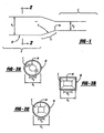
- Figure 1 illustrates the geometry of an extrusion process
- Figure 2 shows various embodiments of extrusion apparatus and dies
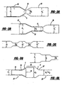
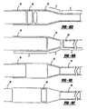
- Figure 3 illustrates a extrusion through a decreasing die.
- Figure 4 shows extrusion through an increasing die.
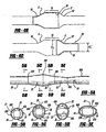
- Figure 5 illustrates extrusion through an isoareal die.
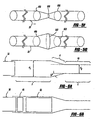
- Figure 6 illustrates use of sacrificial puck in certain embodiments.
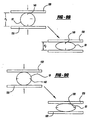
- FIGS 7 and 8 illustrate working the material using rollers.
- Figure 9 shows compression methods of changing the dimensions of the material.
- the words "preferred” and “preferably” refer to embodiments of the invention that afford certain benefits, under certain circumstances. However, other embodiments may also be preferred, under the same or other circumstances. Furthermore, the recitation of one or more preferred embodiments does not imply that other embodiments are not useful, and is not intended to exclude other embodiments from the scope of the invention.
- the word "include,” and its variants, is intended to be non-limiting, such that recitation of items in a list is not to the exclusion of other like items that may also be useful in the materials, compositions, devices, and methods of this invention.
- the invention relates to a method for reducing the free radical concentration in an irradiated crosslinked polymeric bulk material, wherein a polymer is in the form of a bulk material that is elongated in an axial direction said method comprising: • heating the crosslinked bulk material to a compassion deformable temperature; • applying a force to deform the heated bulk material in a direction orthogonal to the axial direction; and • cooling the polymer to a solidification temperature. Fixing the axial direction defines transverse directions that are orthogonal to the axial direction.
- the method involves heating the crosslinked bulk material to a compression deformable temperature, followed by applying a force to deform the heated bulk material in a direction orthogonal to the axial direction. Thereafter, the polymer is cooled to a solidification temperature.
- the polymer resulting from the processing steps is suitable for further processing into bearing components for medical implants.
- the polymeric material comprises ultrahigh molecular weight polyethylene (UHMWPE).
- UHMWPE ultrahigh molecular weight polyethylene
- the UHMWPE is provided in a bulk form characterized by a dimension d 1 in a directional orthogonal to the axial direction.
- the method involves applying pressure on the UHMWPE in a direction orthogonal to the axial direction to reduce the dimension to a value d 2 less than d 1 .
- the orthogonal pressure is relaxed to permit at least a partial recovery of the dimension d 2 to a dimension d 1 greater than d 2 .
- Pressure is then optionally reapplied to reduce the dimension to a value d 2 ' less than d 1 '.
- d 2 ' may be less than, equal to, or greater than d 2 .
- the steps of releasing and reapplying orthogonal pressure are repeated in some embodiments to provide a desired amount of material flow in the bulk UHMWPE. Thereafter, the crosslinked UHMWPE is cooled to a solidification temperature, and a load bearing medical implant component is machined from the cooled UHMWPE.
- the component has a load bearing axis substantially coincident with the axial direction of the crosslinked UHMWPE on which the pressure steps are carried out.
- the bulk polymer is characterized by a dimension d 1 in a direction orthogonal to an axial direction, the applying pressure reduces the dimension to a value d 2 less than d 1 : and after applying pressure and prior to cooling, the process comprises releasing then to permit at least a partial recovery of dimensions d 2 to a dimension d 1 ' greater than d 2 and reapplying the pressure to reduce the dimension to a value d 2 ' less than d 1 '.
- a crosslinked UHMWPE is further characterized by cross-sectional area A 1 in a direction orthogonal to the axial direction.
- the crosslinked UHMWPE has a concentration of free radicals in the bulk material of greater than 0.06 x 10 16 spins per gram.
- the method Involves heating the crosslinked UHMWPE to a compression deformable temperature that is preferably below the crystal melting point. Thereafter, pressure is applied on the UHMWPE bulk material in such a way as to increase the dimension to a value d 2 greater than d 1 , and at the same time to increase the cross-sectional are to a value A 2 greater than A 1 .
- the pressure is relieved to permit a return to a value d 1 ' approximately equal to d 1 , and in aerial value A1' prime approximately equal to A1.
- the crosslinked UHMWPE is then cooled to a solidification temperature.
- the pressure applying and pressure relieving steps are repeated as desired to provide an amount of material flow in the bulk material.
- the method further involves machining a load bearing component from the treated UHMWPE.
- a crosslinked polymeric bulk material is characterized by a free radical concentration above the detection limit (0.06 x 10 15 spins per gram or greater) and the bulk material is characterized as above by an axial direction and further characterized by a cross-sectional area A1 in a transverse section orthogonal to the axial direction.
- the method involves heating the polymeric material to a compression deformable temperature. The heated material is then deformed by extruding it through a die shaped in such a way so as to change the dimensions of the cross-sectional area of the bulk material, but leave the cross-sectional area essentially unchanged. Thereafter the extruded material is cooled.
- a method according to the invention wherein a load bearing medical implant component is machined from cooled UHMWPE, said components having a load bearing axis substantially coincident with the axial direction of the crosslinked UHMWPE, is provided.
- the method comprises crosslinking a UHMWPE bulk material to produce a free radical concentration in the UHMWPE greater than 0.06 x 10 15 spins per gram; heating the crosslinked UHMWPE to a compression formable temperature; extruding the heated UHMWPE, in the form of an elongated bulk material comprising a main access defining an axial direction and a cross-section perpendicular to the axial direction though a die that has a shape different from that of the cross-section, but having an area essentially the same as the cross-section, and further processing the UHMWPE to make the bearing component.
- extrusion, compression, and other pressure applying steps are carried out once or multiple times depending on the desired amount of material "working" and flow desired in the bulk material.
- material flow caused by the application of pressure as described herein is responsible for quenching of free radicals in the polymeric bulk material.
- bulk polymeric materials treated according to the methods described herein tend to have lower free radical concentrations after the deformation pressure is applied.
- deformation pressure is applied to the bulk material in a direction that is perpendicular to the load bearing axis of a medical implant component later to be machined or otherwise produced from the treated bulk material.
- deformation is applied according to the methods described herein in a direction that is orthogonal to the main axis of the polymeric bulk material.
- the main axis of the cylinder, rod, or bar defines the axial direction of the bulk material.
- deformation pressure is applied by extrusion, rollers, or compression in a direction perpendicular to the axial direction.
- implants are manufactured using preformed polymeric compositions having the structures described herein and made by the methods described herein.
- implants include hip joints, knee joints, ankle joints, elbow joints, shoulder joints, spine, temporo-mandibular joints, and finger joints.
- hip joints for example, the preformed polymeric composition can be used to make the acetabular cup or the insert or liner of the cup.
- the compositions can be made used to make the tibial plateau, the patellar button, and trunnion or other bearing components depending on the design of the joints.
- the compositions can be used to make the talar surface and other bearing components.
- the compositions can be used to make the radio-numeral or ulno-humeral joint and other bearing components.
- the compositions can be used to make the glenero-humeral articulation and other bearing components.
- intervertebral disc replacements and facet joint replacements may be made from the compositions.
- the bearing components are made from the polymeric compositions by known methods such as by machining and are incorporated into implants by conventional means.
- preferred polymers include those that are wear resistant, have chemical resistance, resist oxidation, and are compatible with physiological structures.
- the polymers are polyesters, polymethylmethacrylate, nylons or polyamides, polycarbonates, and polyhydrocarbons such as polyethylene and polypropylene.
- High molecular weight and ultra high molecular weight polymers are preferred in various embodiments. Non-limiting examples include high molecular weight polyethylene, ultra high molecular weight polyethylene (UHMWPE), and ultra high molecular weight polypropylene.
- the polymers have molecular ranges from approximate molecular weight range in the range from about 400,000 to about 10,000,000.
- UHMWPE is used in joint replacements because it possesses a low co-efficient of friction, high wear resistance, and compatibility with body tissue.
- UHMWPE is available commercially, for example from Ticona, Inc. of Bishop Texas, which sells the GUR series of resins. A number of grades are commercially available having molecular weights in the preferred range described above.
- the resin is made into bulk materials such as bar stock or blocks using various techniques such as compression molding or ram extrusion.
- the resin is made into a fully consolidated stock in a series of cold and hot isostatic pressure treatments such as described in England et al., U.S. Patent No. 5,688,453 and U.S. Patent No. 5,466,530 , the disclosures of which are hereby incorporated by reference.
- the fully consolidated stock is suitable for subsequent crosslinking and further treatment as described herein.
- a crosslinked polymeric bulk material is further processed in a series of heating, deforming, cooling, and machining steps.
- the polymeric bulk material can be crosslinked by a variety of chemical and radiation methods.
- chemical crosslinking is accomplished by combining a polymeric material with a crosslinking chemical and subjecting the mixture to temperature sufficient to cause crosslinking to occur.
- the chemical crosslinking is accomplished by molding a polymeric material containing the crosslinking chemical.
- the molding temperature is the temperature at which the polymer is molded. In various embodiments, the molding temperature is at or above the melting temperature of the polymer.
- the molding temperature is also preferably high enough to allow the flow of the polymer to occur to distribute or diffuse the crosslinking chemical and the resulting free radicals to form the homogeneous network.
- a preferred molding temperature is between about 130°C and 220°C with a molding time of about 1 to 3 hours. In a non-limiting embodiment, the molding temperature and time are 170°C and 2 hours, respectively.
- the crosslinking chemical may be any chemical that decomposes at the molding temperature to form highly reactive intermediates, such as free radicals, that react with the polymers to form a crosslinked network.
- free radical generating chemicals include peroxides, peresters, azo compounds, disulfides, dimethacrylates, tetrazenes, and divinylbenzene.
- azo compounds are: azobis-isobutyronitrile, azobis-isobutyronitrile, and dimethylazodi-isobutyrate.
- peresters are t-butyl peracetate and t-butyl perbenzoate.
- the polymer is crosslinked by treating it with an organic peroxide.
- Suitable peroxides include 2,5-dimethyl-2,5-bis(tert-butylperoxy)-3-hexyne (Lupersol 130, Atochem Inc., Philadelphia, PA); 2,5-dimethyl-2,5-di-(t-butylperoxy)-hexane; t-butyl ⁇ -cumyl peroxide; di-butyl peroxide; t-butyl hydroperoxide; benzoyl peroxide; dichlorobenzoyl peroxide; dicumyl peroxide; di-tertiary butyl peroxide; 2,5-dimethyl-2,5- di(peroxy benzoate)hexyne-3; 1,3-bis(t-butyl peroxy isopropyl) benzene; lauroyl peroxide; di-t-amyl peroxide; 1,1-di-(t-butylper
- a preferred peroxide is 2,5-dimethyl-2,5-bis(tert-butylperoxy)-3-hexyne.
- the preferred peroxides have a half-life of between 2 minutes to 1 hour; and more preferably, the half-life is between 5 minutes to 50 minutes at the molding temperature.
- the range is between 0.2 to 5.0 wt % of peroxide; more preferably, the range is between 0.5 to 3.0 wt % of peroxide; and most preferably, the range is between 0.6 to 2 wt %.
- the peroxide can be dissolved in an inert solvent before being added to the polymer powder.
- the inert solvent preferably evaporates before the polymer is molded. Examples of such inert solvents are alcohol and acetone.
- the reaction between the polymer and the crosslinking chemical can generally be carried out at molding pressures.
- the reactants are incubated at molding temperature, between 1 to 3 hours, and more preferably, for about 2 hours.
- the reaction mixture is preferably slowly heated to achieve the molding temperature.
- the crosslinked polymer is preferably slowly cooled down to room temperature.
- the polymer may be left at room temperature and allowed to cool on its own. Slow cooling allows the formation of a stable crystalline structure.
- reaction parameters for crosslinking polymers with peroxide can be determined by one skilled in the art. For example, a wide variety of peroxides are available for reaction with polyolefins, and investigations of their relative efficiencies have been reported. Differences in decomposition rates are perhaps the main factor in selecting a particular peroxide for an intended application.
- crosslinking is accomplished by exposing a polymeric bulk material to irradiation.
- irradiation for crosslinking the polymers include electron beam, x-ray, and ⁇ -irradiation.
- ⁇ -irradiation is preferred because the radiation readily penetrates the bulk material.
- Electron beams can also be used to irradiate the bulk material. With e-beam radiation, the penetration depth depends on the energy of the electron beam, as is well known in the art.
- the polymeric bulk material is irradiated in a solid state at a dose of about 0.01 to 100 MRad (0.1 to 1000 kGy), preferably from 0.01 to 10 MRad, using methods known in the art, such as exposure to gamma emissions from an isotope such as 60 Co.
- ⁇ -irradiation is carried out at a dose of 0.01 to 6, preferably about 1.5 to 6 MRad.
- irradiation is to a dose of approximately 5 MRad.
- Irradiation of the polymeric bulk material is usually accomplished in an inert atmosphere or vacuum.
- the polymeric bulk material may be packaged in an oxygen impermeable package during the irradiation step.
- Inert gases such as nitrogen, argon, and helium may also be used.
- the packaged material may be subjected to one or more cycles of flushing with an inert gas and applying the vacuum to eliminate oxygen from the package.
- package materials include metal foil pouches such as aluminum or Mylar® coating packaging foil, which are available commercially for heat sealed vacuum packaging. Irradiating the polymeric bulk material in an inert atmosphere reduces the effect of oxidation and the accompanying chain scission reactions that can occur during irradiation. Oxidation caused by oxygen present in the atmosphere present in the irradiation is generally limited to the surface of the polymeric material. In general, low levels of surface oxidation can be tolerated, as the oxidized surface can be removed during subsequent machining.
- Irradiation such as ⁇ -irradiation can be carried out on polymeric material at specialized installations possessing suitable irradiation equipment.
- the irradiated bulk material is conveniently left in the oxygen impermeable packaging during shipment to the site for further operations.
- the crosslinked polymer is provided in a bulk form characterized by an axial direction and a transverse direction orthogonal or perpendicular to the axial direction.
- pressure is applied to change a dimension in a transverse direction on the crosslinked bulk material to "work" the material and induce at least some material flow in response to the pressure.
- the axial direction corresponds to an elongated dimension or direction of the bulk material, when the material is provided for example in the shape of a cylinder of rod of circular or other cross section.
- the axial direction is essentially parallel to or coincident with the main axis of the material.
- the axial direction does not necessarily correspond visually to an elongated direction, but rather is defined in relation to the direction in which enhanced physical properties such as tensile strength are developed.
- load bearing components are produced from the treated bulk material in an orientation where the load bearing axis corresponds approximately or exactly to the axial direction.
- a set of 3-D orthogonal axes is set up with one of the axes coincident with the axial direction.
- the "z" axis can be taken as coincident with the main cylindrical axis of bulk material in the form of a cylinder.
- the other two axes lie in a plane perpendicular to the axial direction.
- the "x" and “y” axes lie perpendicular to the axial direction, and represent transverse axes or transverse directions in the bulk material.
- the orientation of "x and "y” axes is arbitrary in the transverse plane. When the cross section of the bulk material is circular, all possible orientations of the "x" and "y” transverse axes are equivalent.
- x and "y” components of the bulk material depend on the arbitrarily chosen axes. But in all cases, the shape of the transverse cross section of the bulk material, and the changes in dimension upon application of pressure along those axes, can be expressed as a combination on the basis of the "x" and "y” axes. In various embodiments, a change in dimension in response to an applied pressure occurs in the direction of the applied pressure, which direction can be expressed algebraically and vectorally as a combination of "x" and "y” components.
- the axial direction is constant throughout the bulk material. This is the case for, say, straight cylinders where the (straight) main axis of the cylinder is taken as the axial direction. This is a preferred arrangement.
- the bulk material can also be provided in the form of an elongated body where the main axis changes direction along the axial direction. Such would be the case for bent or curved rods, for tori, and for other closed shapes, by way of non-limiting example.
- the transverse directions are still defined as those directions which are at right angles to the axial direction, whatever the local orientation of the axial direction of the bulk material. The methods described herein are readily adapted to provide changes in dimensions in the bulk material at right angles to the (local) axial direction.
- the shape of the cross section transverse to the axial direction of the bulk material is not particular limited and includes circles and their topological equivalents (such as ovals, ovoids, ellipses, and other areas bounded by a closed curve), as well as other shapes.
- Non-limiting examples of shapes include regular and non-regular polygons (e.g. squares, rectangles, rhombus, and trapezoids for four sided figures), stars, convex shapes, and concave shapes. Certain shapes are preferred because of their relative ease of manufacture. Such include circular cross-sections, readily produced by RAM extrusion for example.
- the axial direction is the direction in which higher tensile strength is developed, as described further below.
- the axial direction of the bulk material is the direction perpendicular to the dimensional change in the transverse direction that results from application of pressure.
- application of pressure or force orthogonal to the axial direction creates an anisotropic material, characterized by higher tensile strength in the axial than in the transverse direction.
- the axial direction of the bulk material also defines the preferred direction in which implant bearing components such as acetabular cups are to be machined. That is, bearing components are preferably made or machined from the treated bulk polymer in an orientation where the higher tensile strength axis of the polymeric bulk material corresponds to the load bearing axis or direction of the bearing component of the implant in vivo.
- the bulk material is in the form of a rod or cylinder having a circular cross section.
- the axial direction is parallel to the main axis of the cylinder, while the transverse directions are at right angles to the axial direction.
- the existence of the axial direction defines an orthogonal direction referred to as "transverse” in this application.
- the transverse direction can be described as "radial”, and the transverse axis as a radial axis.
- the main axis of the bulk material can also be called the longitudinal axis.
- the longitudinal axis is parallel to the axial direction.
- a cross section of the bulk material perpendicular to the axial direction or longitudinal axis is a circle.
- Other bulk materials characterized by an axial direction may be used that have other perpendicular cross sections.
- a square cylinder can be provided that has a square cross section perpendicular to the axial direction.
- Other bulk materials characterized by an axial direction can have rectangular, polygonal; star, lobed, and other cross sections perpendicular to the axial direction.
- the axial direction of the bulk polymeric material is elongated compared to the orthogonal or radial direction.
- a commercially available bulk material is a cylinder approximately 3 inches in diameter and 14 inches in length. The length corresponds to the axial direction and the diameter corresponds to the radial direction.
- bearing components for implants are preferably machined from billets cut in the axial direction
- the bulk material is usually to be extended in an axial direction so as to be able to cut a plurality of billets from the material for use In further machining of the bearing components.
- bulk material characterized by an axial direction is further characterized as having a variety of cross sectional areas in a transverse section orthogonal to the axial direction.
- the dimensions of the cross sectional areas perpendicular to the axial direction are more or less constant along the axial direction from the beginning to the end or from the top to the bottom of the bulk material.
- bulk materials may be provided to have cross sectional areas that vary along the length or axial direction of the bulk material. In the case where the cross sectional area of the bulk material is constant along the axial direction of the bulk material, compressive force applied as described below will generally be applied to the bulk material in a direction perpendicular to the axial direction.
- compressive force applied to the bulk material may have a component in the axial direction due to the geometry of the bulk material. However, in all cases at least a component of the compressive force will be applied on the bulk material in a direction orthogonal to the axial direction.
- the crosslinked polymer is heated to a compression deformable temperature.
- the compression deformable temperature is temperature at which the polymeric bulk material softens and can flow under the application of a compressive source to change dimension in the direction the compressive force is applied.
- the compression deformable temperature is concretely from about the melting point minus 50°C to the melting point plus 80°C.
- the compression deformable temperature is below the melting point of the polymeric material.
- the compression deformable temperature include from the melting point to 10°C below the melting point, from the melting point to 20°C below the melting point, from the melting point to 30°C below the melting point, and from the melting point to 40°C below the melting point.
- the compression deformable temperature is preferably above 80°C, or from about 86°C to about 136°C, since the melting temperature of the UHMWPE is about 136°C to 139°C.
- the compression deformable temperature of UHMWPE lies from about 80°C to 135°C, preferably about 100°C to 130°C.
- a preferred temperature is 125 - 136°C, or 130°C ⁇ 5°C.
- the crosslinked material can be heated to a compression deformable temperature above the melting point of the polymer.
- a compression deformable temperature is from just above the melting point to a temperature about 80°C higher than the melting point.
- UHMWPE can be heated to a temperature of 160°C to 220°C or 180°C to 200°C.
- the bulk polymeric material it is preferred to heat the bulk polymeric material to a compression deformation temperature close to but not higher than the melting point.
- the compression deformable temperature is between the melting point and a temperature 20°C lower than the melting point, or between the melting point and a temperature 10°C lower than the melting point
- the crosslinked bulk material can be heated to a compression deformable temperature in a deformation chamber as illustrated in the figures, or it can be preheated in an oven to the compression deformable temperature.
- the bulk material is heated to a temperature Just below the melting point, such as the melting point minus 5° or the melting point minus 10° and placed in a heated deformation chamber.
- the deformation chamber preferably maintains a compression deformable temperature. If desired, the deformation chamber can be heated or thermostatted to maintain a constant temperature. Alternatively, the deformation chamber is not itself heated but has sufficient insulating properties to maintain the bulk material at a compression deformable temperature during the course of pressure application described below. In various embodiments, the temperature of the deformation chamber is held at several degrees below the melting temperature to avoid melting.
- Any suitable methods may be used to apply the compression force in a direction orthogonal to the axial direction.
- Non-limiting examples include extrusion through dies and the use of rollers, compression plates, clamps, and equivalent means.
- deforming force is applied in the direction orthogonal to the axial direction of the bulk material by extruding the bulk material through a die or series of dies. Extrusion through the die or dies is carried out in the axial direction of the bulk material.
- Suitable dies can be manufactured by traditional machining methods, by electrical discharge machining, or by other techniques well known in the machine tool art.
- a die used in the extrusion processes has a shape and size selected to apply pressure in a transverse direction to the bulk material in the desired fashion.
- shapes include, without limitation, circles and their topological equivalents, shapes bounded by closed curves, shapes bounded by a closed curve made up of straight segments and curved segments, regular polygons, and non-regular polygons.
- the die has one or more of concave shapes, convex shapes, smooth shapes (for example, having a continuous derivative), smooth shape with a kink or kinks (for example, points where the derivative is non-continuous), or shapes bounded by straight lines (e.g: regular and non-regular polygons).
- certain die shapes are preferred for their ease of manufacture.
- the choice of die shape is also to be made in consideration of compatibility with the shape and size of the bulk material to be worked.
- extruding converts the pressure of an extrusion ram in an axial direction to pressure in the transverse direction applied by the die.
- extrusion is accomplished with a reduction in cross-sectional area (a "reducing die"), with an increase in cross-sectional area (an “increasing die”) or with no change in cross-sectional area (an “icreaseal die”).
- a reducing die has a cross-sectional area that is less than the cross-sectional area of the piece to be extruded through the die.
- pressure exerted on the bulk material in a direction orthogonal to the axial direction causes at least one transverse dimension of the bulk material to be reduced compared to the original dimension of the bulk material.
- the diameter or other transverse dimension of the bulk material after extrusion is less than the dimension before extrusion.
- the relative reduction in the dimension of the bulk material in the transverse directions can be expressed as a ratio of the original dimension d 1 to the reduced dimension d 2 .
- the numeric value of the ratio d 1 /d 2 can be referred to as a draw ratio or a diametral compression.
- draw ratio For extrusion, it is common practice to refer to a draw ratio; unless stated otherwise from context, the term draw ratio will be used here to refer to all geometries.
- the transverse direction (the direction orthogonal to the axial direction) itself contains two axes that can be drawn at right angles to the longitudinal axis.
- the bulk material can be deformed by a different amount along the two transverse axes, and a draw ratio can be defined for both axes (or, equivalently, any linear combination of the two axes).
- the orientation of the transverse axes is arbitrary; if needed for analysis, the axes can be selected to simplify the geometry of the applied forces.
- the cross section of the bulk material is circular, equal deformation force can be applied in all transverse directions by extruding through a circular reducing die.
- the dimension d 2 corresponds to the radius or diameter of the extruded material
- the draw ratio is the fraction defined by dividing d 1 by d 2 .
- the draw ratio is 1.1 or higher, and less than about 3. In various embodiments, the draw ratio is 1.2 or higher, and is preferably about 1.2 to 1.8. It is about 1.5 in a non-limiting example. Minimum levels of draw ratio provide sufficient material flow in the crosslinked material to provide benefits described herein. As the crosslinked material is "worked" to a greater extent, the dimensions in the transverse direction change to a greater extent, thus increasing the calculated draw ratio. As the draw ratio is increased, a point is eventually reached at which the strain introduced by the dimension change is too great and the properties of the crosslinked polymeric materials deteriorate. Accordingly, in various embodiments the draw ratio is 3.0 or less, 2.5 or less, and preferably about 2.0 or less.
- the compressive force is applied more or less isotropically around the bulk material in a direction transverse to a longitudinal axis. Accordingly, the reduction in dimension will usually apply in all transverse directions. To illustrate, a circular cross section remains round but is reduced in diameter, while a polygonal cross section such as a square or rectangle is reduced on all sides.
- the two dimensions of the workpiece orthogonal to the long axial direction change by different amounts. At least one is reduced to such an extent that the cross-sectional area of the die is less than that of the workpiece.
- dies that apply force or pressure anisotropically include ovals, rectangles, and other "asymmetric" shapes. Asymmetric shapes include those resulting from deformation of a circle, such as ellipses, ovals, and the like.
- FIG. 1 The geometry of extrusion through a reducing die is illustrated in schematic form in Figures 1 and 2 .
- a reducing die 6 is disposed between a deformation chamber 2 and a holding chamber 4.
- the holding chamber has the same diameter as the die.
- it is equipped with water or other cooling means to slowly cool the extruded material from its compression deformable temperature.
- the figure is shown in a cross sectional view to illustrate that the reducing die 6 reduces the diameter or dimension of the extruded material from an original dimension d 1 to an extruded dimension d 2 , as extrusion is from left to right in the Figure.
- the crosslinked heated bulk material passes from the deformation chamber through the reducing die 6, the material flows by the die wall 5 that leads to a constriction 10 having the diameter d 2 of the cooling chamber 4.
- FIG. 2 Various geometries of the reducing die are illustrated in non-limiting form in Figure 2 .
- Figures 2a to 2e show the relative configuration of the deformation chamber wall 20 and the die constriction 10.
- the die wall 5 is seen to connect the cooling deformation chamber to the cooling chamber.
- the cross section of both the deformation chamber 2 and cooling chamber 4 are circular (indicated with the illustration of the relative disposition of the chamber wall 20 and the restriction 10), with dimensions d 1 and d 2 corresponding to their respective diameters.
- the deformation chamber is square or rectangular characterized by a dimension d 1 that can be arbitrarily taken along a diagonal or along a side.
- the restriction 10 is also rectangular but having lower dimension d 2 .
- Figures 2c through 2e illustrate other combinations of circular, square, and triangular deformations and cooling chambers connected by reducing dies 6 having a die wall 5, and are offered by way of non-limiting example.
- the bulk material in the deformation chamber 2 is held at a compression deformable temperature. At such a temperature, the material can flow in response to pressure exerted on the material. When the compression deformable temperature is below the melting point, the material undergoes a solid state flow through the reducing die 6. Pressure or force applied to the end of the bar by the ram is translated by the die into compressive force that reduces the dimension of the bulk material in the transverse direction.
- the deformation chamber illustrated in Figure 1 can be sized to match relatively closely the diameter or dimension d 1 of the bulk material to be extruded.
- the material When the material is extruded into a holding chamber as illustrated in Figure 1 , as noted the material can be cooled down while being held in a deformed state to the extent that d 2 is less than d 1 . Alternatively, the material can extruded through the die into a region of ambient pressure, allowing the bulk material to immediately recover from the dimension change from d 1 to d 2 . When not held at a reduced dimension, the extruded crosslinked material tends to return at least somewhat to its original shape, so that d 2 tends to recover approximately to its original dimension d 1 . Normally, the recovery occurs within seconds of being extruded through the die into ambient pressure conditions.
- Extruding the bulk material at draw ratios of about 1.1 or higher as described above works the extruded material by inducing material flow as the dimensions are reduced by passing through the extrusion die.
- the amount of the working is determined by the relative draw ratio.
- preferred draw ratios are 1.1 or higher and less than about 3.
- One way of increasing the working of the material without overly increasing the draw ratio is to carry out a sequential extrusion of the bulk material through a die.
- the method involves extruding the bulk material through the reducing die, collecting the material as it comes out the die, and providing the material as input to another die or the same die. In this way, the material can be re-extruded to provide a desired amount of working, which leads to reduction in the level of free radicals in the material.
- Non-limiting embodiments of the sequential extrusion are illustrated in Figure 3 .
- Figure 3a shows extrusion of a bulk material 50 through a constriction 10 in a die that reduces the dimension from d 1 to d 2 in the transverse direction.
- the pressure applied by the constriction is relieved (by passing into a region of ambient pressure) and the dimension of the bulk material tends to increase to a dimension d 1 ', which is generally the same as or slightly less than the original dimension d 1 .
- the bulk material 50 can be re-extruded through the die shown in Figure 3a .
- a bulk material of dimension d 1 ' is extruded through the reducing die.
- the diameter is given as d 1 ", which as before tends to be about the same or slightly less than d 1 '.
- FIG. 3b An alternative embodiment is shown in Figure 3b .
- the bulk material 50 is extruded through a constriction 10 into a chamber 15 having a dimension d 2 of less than the original dimension d 1 .
- the extrusion apparatus is sized so that the bulk material has a higher volume than chamber 15.
- the bulk material is extruded out of the apparatus, whereby it regains dimension to a value d 1 ' that, as before, is approximately the same as or slightly less than the original d 1 .
- the worked materials 50 can be re-extruded as before.
- FIG. 3a and 3b are characterized as multiple extrusions through a single die.
- Working can also be provided by extruding through a series of dies as illustrated in non-limiting fashion in Figures 3c and 3d.
- Figure 3c shows a series of dies that take the diameter of the bulk material from an original diameter d 1 to a first constricted diameter d 2 to a second expanded d 1 ' to a second restricted diameter d 2 and finally to a final dimension d 1 ".
- FIG. 3d Another embodiment is shown in non-limiting fashion in Figure 3d , where a series of dies is set up to take bulk material from an original dimension d 1 to a second dimension d 2 to a third dimension d 3 . As before, it is contemplated to extrude the bulk material through the apparatus, whereby the dimension recovers to a value close to or slightly less than the original dimension d 1 . If desired, material that has been passed through a series of dies as shown in non-limiting fashion in Figures 3c and 3d can be re-extruded through the same apparatus or through apparatus such as shown in Figure 3a and 3b . In all cases, re-extrusion works the material further, which generally leads to a reduction in concentration of free radicals, for example in the crystalline regions of the bulk material.
- the material is extruded through a series of dies as illustrated in Figure 3 , but into a holding chamber or other device to maintain the dimension of the extruded material at a reduced value compared to the original dimension d 1 .
- the material is then cooled while maintaining the compressed state.
- FIG. 4 Another way of working the crosslinked material to reduce the level of free radicals is to induce flow in the bulk material by extruding it in an increasing die.
- the temperature is below the crystalline melting point of the UHMWPE or other crosslinked material
- the flow in the bulk material is characterized as solid state flow.
- the method is illustrated in non-limiting fashion in Figure 4 .
- Figure 4a shown in cross section, the bulk material 50 is extruded through a restriction 10 into an area of increasing volume defined by the walls 5 to a chamber 15 that is characterized by a dimension d 2 that is greater than dimension d 1 .
- Back pressure is provided by any suitable means, such as without limitation with a ram, with a sacrificial puck set up as described below, or with fluid pressure.
- the dimension d 2 tends to return to a value close to the original dimension d 1 .
- the extrusion apparatus further comprises a decreasing wall 5' leading to a second constriction 10' that defines a reducing die as illustrated for example in Figure 3 .
- a second constriction 10' defines a reducing die as illustrated for example in Figure 3 .
- the bulk material is further extruded through a decreasing die as further illustrated in Figure 4c to bring the dimension back to a value d 1 ' which is less than d 2 .
- the bulk material is extruded through a series of increasing dies analogous to that shown in Figure 3d for the decreasing die.
- the bulk material 50 is worked by extruding through a sequence of increasing and decreasing dies as illustrated schematically in Figure 4 .
- the bulk material is worked by extruding through a die that changes the dimensions of the cross section of the elongated bulk material being extruded, but does not substantially change the cross sectional area.
- Working of the bulk material is provided by extruding, although no net change in area occurs.
- the isoareal extrusion is advantageous because the extrusion requires less ramming force, since there is less resistance to flow because of the small or zero value net area change in the cross section.
- the die itself can be conceptualized as providing a first cross sectional area, which in most practical applications is substantially the same as the cross section of the bulk material to be worked.
- the isoareal die also provides a second cross sectional area which has the same cross sectional area, but has different dimensions.
- the first shape is a circle and the second shape is an oval or ellipse having the same area as the circle.
- the dimension of the circle is conveniently given by a radius or diameter, while the dimensions of the oval are provided by a major and minor axis.
- isoareal circles and ovals are selected to give isoareal circles and ovals according to well known geometrical principles.
- the method can be generalized to provide isoareal shapes for any arbitrary starting configuration of the bulk material.
- a common bulk form of crosslinked UHMWPE is a cylinder of approximately 3 inches in diameter and 14 inches in length. Accordingly, isoareal extrusion is provided for the exemplary crosslinked bulk material if the second shape has a cross sectional area of approximately 7.06 square inches ( ⁇ d 2 /4 when the diameter d is 3 inches).
- the cross sectional area in this transition zone is the same as the first shape and the second shape, as it "morphs" from the first shape to the second shape to provide isoareal restriction.
- the absolute requirement of mathematical precision in the machining of such die shapes and transitions zones is relaxed slightly; the key feature of this aspect is that, due to the approximately equal areas of the two shapes, extrusion through the die takes place with a minimum of power input to provide advantages as described herein.
- Figure 5a shows an extrusion apparatus, where 20 is the wall of an elliptical die tool.
- the extrusion apparatus is illustrated showing isoareal extrusion shapes indicated as 200, 300, 400, 500, and 600.
- the shapes are connected by transition zones having inner walls 21, 22, 23, and 24.
- a view along cut line 5b illustrates that in relation to circular shape 200, shape 300 is a vertical oval.
- the view along 5c shows that shape 400 goes back to a circle.
- the view along line 5d shows that isoareal shape 500 is an oval turned at 90° to the oval of shape 300.
- the view along line 5e shows shape 600 is again a circle.
- a crosslinked bulk material is accomplished as before by pushing a bulk material (not shown) through a die or series of dies illustrated as 200, 300, 400, 500, and 600 in Figure 5 .
- the bulk material can be further worked by subsequent re-extrusion through the same apparatus.
- isoareal extrusion in various embodiments it is preferred to provide a plurality of isoareal restriction steps, including changes in shape along different axes. This provides material flow in more than one dimension and tends to lead to better free radical concentration reduction induced by the material flow.
- FIGS 5f and 5g show the oval isoareal shape 500 disposed between two circular die shapes 400 and 600.
- a so-called sacrificial puck is used to improve the efficiency of the extrusion process.
- the concept of using a sacrificial puck is illustrated in Figure 6 ; its use is readily adapted to other configurations.
- a ram 30 is provided in a retracted position with respect to the deformation chamber 2.
- Figure 3b shows the ram 30 retracted and the deformation chamber 2 filled with a rod-like bulk material 50 and a sacrificial puck 40.
- the sacrificial puck 40 is preferably made of a crosslinked polymer, which may be the same as the crosslinked polymer of the bulk material 50. It is preferably of approximately the same cross-sectional shape and area as the bulk material 50 to be extruded.
- FIG 3c the ram 30 is shown pushing on the sacrificial puck 40, which in turn pushes on the bulk material 50 to move the bulk material 50 through the reducing die 6 into the cooling chamber 4.
- Figure 3d shows the situation at the end of the stroke of the ram 30.
- the bulk material 50 is sitting completely in the cooling chamber 4, while the sacrificial puck 30 occupies the reducing die 6.
- the sacrificial puck 40 tends to return to its original dimension because it is not being cooled in the cooling chamber as the bulk material 50 is.
- the sacrificial puck tends to extricate itself from the reducing die as shown in Figure 3f.
- the sacrificial puck 40 can then be removed from the deformation chamber and the process repeated after a cycle time in which the bulk material 50 cools to a suitable solidification temperature as discussed above.
- working of bulk material according to the invention is provided by passing the bulk material between sets of rollers, while applying force to the bulk material by means of the rollers to change a dimension of the material in the transverse direction.
- the geometry of a roller system is illustrated in a simple system in Figure 7 .
- Figure 7a shows a perspective view of a bulk material in the shape of a cylinder as it is passed between rollers 100.
- the view of Figure 7b is down the axial direction of the bulk material 50.
- Pressure is applied to the rollers as indicated by the arrows in Figure 7b to change the dimension from d 1 to d 2 , as illustrated in Figure 7c .
- rollers can be used to apply a compression force in a direction orthogonal to the axial direction.
- the rollers 100 normally have roller or other means for advancing the bulk material 50, while passing the material between rollers that provide pinch points or restrictions.
- Working of the material is accomplished in some embodiments by passing the material between a single set of rollers. If desired, additional working can be accomplished with a single set of rollers by rolling the material back and forth between the rollers, and/or by passing the material between the rollers more than once.
- the rollers are spaced sufficiently far apart and the velocity of the rollers is selected to provide restriction points far enough apart that the compressed dimension of the material after passing through the first rollers recovers at least in part before being recompressed with a second set of rollers.
- a second set of rollers This is illustrated in Figure 8 .
- the original dimension d 1 is reduced to d 2 and recovers to d 1 ' after the first set of rollers.
- the second set of rollers compresses the dimension to d 2 ', while after the second rollers the dimension increases to d 1 ", which is about the same as d1.
- the multiple rollers showed in non-limiting fashion in Figure 8 can be set up or programmed to reverse to provide a back and forth movement of the material between the rollers. In this way, a desired amount of working can be applied in a mechanically convenient way. As before, the dimension of the material tends to recover once the pressure applied by the rollers is relieved.
- a series of rollers is provided close enough together that the dimension of the material does not fully recover in the time it takes the material to travel between the individual pairs of rollers in the series.
- a series of rollers is used to provide pressure along a relatively long section of the bulk material 50 as it is transported by the motion of the rollers. Such a situation is illustrated by Figure 7a , in a non-limiting configuration.
- the individual sets of rollers are provided with offset configurations.
- a first set of rollers is provided in a first orientation as illustrated in non-limiting fashion in Figure 7b .
- a second set of rollers is provided in a second orientation, for example according to the illustration in Figure 7d .
- Figure 7c represents deformation in a first transverse direction to decrease the dimension to d 2
- Figure 7d represents deformation in a second transverse direction.
- the material can be worked to a desired extent to accomplish a reduction in the free radical concentration induced in the material by the crosslinking step.
- rollers provide constrictions or pinch points that change the dimension of the material being worked in order to induce a desired amount of material flow. It is also appreciated that not all the rollers in a system need be drive rollers. Rather, one of more of the rollers can be configured to provide movement to the material, while the others can be configured to provide compression only.
- the material is treated with rollers while being maintained at a compression deformable temperature, for example in a constant temperature oven.
- the working of the material by rollers occurs in ambient conditions to permit the material to cool at the same time it is being worked.
- the pressure of the rollers applied over time can be varied, for example to slowly reduce the pressure applied (and thus the dimension change induced in the transverse direction) until the material has reached a solidification temperature.
- rollers are configured to provide a desired pressure regime about the cross-sectional area of the bulk material.
- a 2-roller system is illustrated in Figure 7a
- 3-roller systems are illustrated in Figure 7f
- 4 -roller systems are illustrated in Figure 7g .
- the amount of working is also varied in various embodiments by providing roller means with varying speeds.
- the time that the bulk material spends in a compressed state due to the action of the rollers is inversely proportional to the speed by which the rollers move the bulk material through the apparatus.
- a compression ratio can be defined that is analogous to the draw ratio defined for extrusion. Referring to Figure 7 , the compression ratio is defined by the ratio of the original dimension d 1 to the compressed dimension d 2 . In various embodiments, preferred values for the restriction ratio take on the same values as the draw ratio for the extrusion embodiment.
- Figure 9 Another way of working the material by changing a dimension in the transverse direction is to apply pressure between plates in a compression molding fashion.
- the process is illustrated in a non-limiting way in Figure 9 .
- Figure 9a shows a perspective drawing of an elongate bulk material 50 between the plates 150 of a compression molding apparatus. Tick marks 140 show the relative orientation of the bar 50 between the plates 150.
- Figure 9b shows, in cross sectional view looking down the axial direction of the bulk material (show for illustration as a cylinder with circular section), the plates 150 in contact with the material before and after reduction of the transverse dimension from d 1 to d 2 .
- a compression ratio is defined as d 1 / d 2 , which in various embodiments takes on preferred values such as those given above for draw ratio in the extrusion case.
- the pressure is optionally relieved (not shown) and the material is cooled.
- the material 50 is subjected to a series of compressions to provide a desired amount of working of the bulk material. Subsequent compressions can take place with the material in the same orientation as for the first compression. In various embodiments, subsequent compressions are made with the material in a different orientation with respect to the plates. As illustrated by Figure 9c in a non-limiting fashion, the material is turned 90° from its first orientation, and compression force is again applied. In various embodiments, the process of compression and pressure relief is repeated using various orientations to achieve a desired amount of working of the bulk material.
- Figure 9 shows the compressive plates oriented parallel to one another, so that compression occurs to an equal extent all along the bulk material.
- the compressive method is completely general, allowing for compression between plates that are tilted relative to each other, so as to provide an unequal compression ratio along the bulk material.
- subsequent compressions can be carried out in the same or different configuration to provide the desired amount of "working" and material flow throughout the treated bulk material.
- the orientation of the plates during contact with the bulk material is changed during contact to provide a kind of rolling massage along the length of the axial direction of the bulk material.
- At least one of the plates 150 is provided with a curvature so that a rolling contact is maintained between the bulk material and two curved plates or a flat plate and a curved plate. It is readily seen that embodiments with curved plates in arrangements like Figure 9 have many features in common with the process of applying pressure with rollers described above.
- the methods described herein - extrusion, treatment by rollers, and compression molding involve the application of pressure to a bulk material in such a way that a dimension in the transverse direction of the bulk material is changed from its original value.
- pressure is applied in the transverse direction to change the dimension.
- pressure or back pressure is applied in the axial direction to provide for the material flow.
- the bulk material tends to undergo a recovery in dimensions back to approximately the starting value, due to the crosslinked nature of the bulk material on which the pressure is being applied.
- the methods call for sequential pressuring and relief of pressure to produce a working or kneading of the material.
- the methods provide for a single compression and a single pressure relief step.
- the pressure is relieved and the temperature is still above the solidification temperature (see below)
- the dimension reduced by application of pressure tends to recover to approximately its original value.
- the cross sectional area of the elongated bulk material changes (decreases or increases) in response to the applied pressure; upon relief, the cross sectional area tends to return to approximately its original value.
- the cross sectional area essentially does not change (examples are the isoareal dies, compression between rollers, and compression between plates) but at least one dimension in the transverse direction is decreased; upon relief, the dimensions tend to return to their original values and the shape to the original shape.
- the polymeric material is cooled before further processing.
- the extruded bulk material can be directly processed by the stress relief step described below.
- the rod or other bulk material characterized by an axial direction is cooled to a solidification temperature in a cooling chamber or other means while pressure is maintained sufficient to keep the dimension of the extruded bulk material below the original dimension of the crosslinked bulk material.
- the pressure required to maintain the dimension lower than the original dimension may be more or less pressure than required to originally change the shape of the polymer, such as through extrusion.
- the bulk material such as extruded UHMWPE is held in a cooling chamber or similar device for a sufficient time to reach a temperature at which the bulk material no longer has a tendency to increase in dimension upon removal of the pressure.
- This temperature is designated as the solidification temperature; for UHMWPE the solidification temperature is reached when a thermostat embedded in the cooling wall (about 1 mm from the inside wall surface) reads about 30°C.
- the solidification temperature is not a phase change temperature such as a melting or freezing. It is also to be noted that a material such as UHMWPE can be cooled to the solidification temperature independently of whether the material was heated above or below the melting point in a previous processing step.
- the compressive deforming force is maintained on the bulk material until the bulk material cools to the solidification temperature.
- a maintenance of compressive force is conveniently provided in the reducing die embodiment illustrated in Figures 1 and 2 .
- the bulk material is held in the cooling chamber 4.
- the cooling chamber is of such a size and shape as to hold the extruded bulk material at a dimension or diameter d 3 , which is less than the original dimension d 1 of the bulk material and is conveniently about the same as the extruded dimension d 2 in a non-limiting example.
- the crosslinked material has a tendency to return to its original dimension by expanding when the temperature is above the solidification temperature.
- the expansion force of the bulk material is counteracted by the walls of the cooling chamber, with the result that compressive force is maintained on the bulk material while it cools.
- the cooling chamber is provided with cooling means such as cooling jackets or coils to remove heat from the cooling chamber and the extruded polymer bulk material.
- the polymeric extruded bulk material cools in the cooling chamber, a temperature is reached at which the material no longer has a tendency to expand or revert to its original dimension d 1 .
- the solidification temperature the bulk material no longer exerts pressure on the walls of the cooling chamber and can be removed.
- the material is cooled to about 30°.C, as measured by thermostats in the walls of the chamber, before removal.
- the temperatures of the deformation chamber and the cooling chamber can be measured by conventional means, such as by thermocouples embedded into the walls of the respective chambers. For example, it has been found that when a thermocouple in the wall of the cooling chamber indicates a temperature of 30°C, an extruded bulk material made of UHMWPE has reached a bulk temperature below a solidification temperature at which the material loses it tendency to expand.
- the temperature as measured with, for example, a thermocouple embedded in the wall of the cooling chamber does not necessarily represent a bulk or equilibrium temperature of the material in the cooling chamber.
- cooling to a solidification temperature of, for example, 90°F or 30°C means leaving the extruded bulk material in the cooling chamber until the thermocouple embedded in the walls of the cooling chamber reads 90°F or 30°C. As noted, it has been found that such a cooling period suffices for removal of the bulk material, even though the bulk equilibrium temperature of the interior of the bulk material could be higher than the measured temperature.
- the extruded bulk material is held in the cooling chamber for an additional period of time, such as 10 minutes, after the embedded thermocouple reads 90°F or 30 °C.
- the additional cooling period can enable the cooled material to be more easily removed from the cooling chamber.
- a programmable logic controller plc
- plc programmable logic controller
- the compression deformed and worked material is allowed to cool without applied pressure.
- the workpiece tends to return to the original dimensions it had before the working.
- the piece is extruded into air or into a cooling chamber of dimension approximately equal to that of the original workpiece. If rollers are used to compress and work the material, the roller tension can be removed and the material allowed to cool.
- the dimensions of the bulk materials tend to return to approximately their original values. This is consistent with a certain amount of "shape memory" that is characteristic of crosslinked polymeric materials. Usually, however, the return to original dimensions is not 100%; under various models this is ascribable to incomplete return to an original equilibrium condition, to lack of an equilibrium condition in the first place, or even to a series of small irreversible changes in structure as a result of the working. Up to a certain point, such non-equilibrium conditions can be avoided or mitigated by operating at suitably low levels of draw ratio or compression ratio in the working steps described herein. But to a certain extent, some such small deviations from equilibrium are unavoidable. As a result, the worked and cooled material contains a certain amount of internal stress. Such stress is subject to relief over time when held at physiological conditions, which could lead to dimension changes and the like of the installed implant. This would be of course undesirable.
- the bulk material is preferably stress relieved following working of the material in the transverse direction and optional cooling to a solidification temperature, and prior to being machined into a bearing component for use in a medical implant such as an artificial joint.
- stress relieving is carried out by heating to a stress relief temperature, preferably below the melting point of the polymeric bulk material. If the cooling in the previous step is carried out while maintaining deformation force, the bulk material on stress relieving tends to expand and return to a dimension close to its original dimension.
- the diameter d 3 of the rod tends to increase to a diameter approaching d 1 of the original bulk material.
- the bulk material is heated in an oven, is heated by infrared radiation, is subject to microwave radiation, or is treated with ultrasonic energy.
- the methods tend to increase the temperature of the bulk material and provide a thermal defect.
- some of the methods for example ultrasound, provide various energy other than thermal energy to provide for the stress relieving.
- stress relief temperatures close to but less than the melting temperature are preferred, for example from the melting point to the melting point minus 30 or 40°C.
- preferred stress relief temperatures include in the range of about 100°C to about 135°C, 110°C to about 135°C, 120°C to 135°C, and preferably 125°C to about 135°C.
- Stress relieving is carried out for a time to complete the stress relief process.
- suitable times range from a few minutes to a few hours.
- Non-limiting examples include 1 to 12 hours, 2 to 10 hours, and 2 to 6 hours in an oven or other suitable means for maintaining a stress relief temperature.
- the stress relieving can be carried out in a vacuum, in an inert atmosphere, or in a package designed to exclude an atmosphere, it is preferably carried out in an air atmosphere.
- the solidified extruded bulk form exhibits a tendency to bend or otherwise deviate from a preferred straight or linear orientation during the heating or other treatment associated with stress relieving.
- the bulk material is held in a mechanical device that functions to keep the bulk material straight (measured on the axial direction) during the stress relieving step.
- the bulk material is placed into V-channels to keep it straight.
- V-channels are equally spaced from each other and are part of the same physical structure.
- the several V-channels may, for example, be welded to the structure at equal spacings.
- the extruded bars are positioned on a bottom set of V-channels and then another set of V-channels is set on top of the extruded bars to rest on top of the bars. These channels help to keep the bars straight during stress relieving.
- the product of the crosslinking, heating, compressing (working), cooling, and stress relieving steps is a bulk material having dimensions approximately equal to the original bulk material before crosslinking.
- the bulk material exhibits high tensile strength in the axial direction, a low but detectable level of free radical concentration, and a high degree of resistance to oxidation.
- a bulk material having an original dimension or diameter of d 1 is crosslinked and heated to a compression deformation temperature.
- the crosslinked heated material is then compressed to a dimension or diameter d 2 which is less than d 1 .
- the material is then held while cooling at a diameter d 3 that may be the same as d 2 , but in any case is less than the original dimension or diameter d 1 .
- stress relieving returns the bulk material to a diameter d 4 which is greater than d 3 and in some embodiments is approximately equal to the original dimension or diameter d 1 .
- the original bulk material is a 3" x 14" cylinder of UHMWPE
- the treated preform resulting from the steps above preferably typically has a diameter of about 2.7 to 3 inches.
- the bulk material characterized by an axial direction is machined according to known methods to provide bearing components for implants.
- the cylinder is then cut into billets along the axial direction, and each billet is machined into a suitable bearing component.
- the bearing components are machined from the billets iri such a way that the in vivo load bearing axis of the bearing component corresponds to the axial direction of the bulk preform from which it is machined. Machining this way takes advantage of the increased tensile strength and other physical properties in the axial direction of the preform.
- the stresses at the bearing surface are typically multiaxial, and the magnitude of the stresses further depends on the conformity of the joint.
- the polar axis of the cup is aligned with the longitudinal axis of the extruded rod, corresponding to the axial direction.
- the wall of the cup, at the equator and rim, is parallel to the long axis of the rod, and will benefit from the enhanced strength in this direction during eccentric and rim loading scenarios.
- UHMWPE preforms, and bearing components made according to the invention have a high level of oxidative resistance, even though free radicals can be detected in the bulk material.
- an oxidation index by infrared methods such as those based on ASTM F 2102-01.
- ASTM F 2102-01 an oxidation peak area is integrated below the carbonyl peak between 1650 cm -1 and 1850 cm -1 .
- the oxidation peak area is then normalized using the integrated area below the methane stretch between 1330 cm -1 and 1396 cm -1 .
- Oxidation index is calculated by dividing the oxidation peak area by the normalization peak area.
- Oxidative stability can then be expressed by a change in oxidation index upon accelerated aging. Alternatively, stability can be expressed as the value of oxidation attained after a certain exposure, since the oxidation index at the beginning of exposure is close to zero.
- the oxidation index of crosslinked polymers of the invention changes by less than 0.5 after exposure at 70°C to five atmospheres oxygen for four days. In preferred embodiments, the oxidation index shows a change of 0.2 or less, or shows essentially no change upon exposure to five atmospheres oxygen for four days. In a non-limiting example, the oxidation index reaches a value.
- the oxidation index attains a value no higher than 0.2 after two or after four weeks exposure at 70° to 5 atm oxygen, and preferably no higher than 0.1.
- the specimen shows essentially no oxidation in the infrared spectrum (i.e. no development of carbonyl bands) during a two week or four week exposure.
- Oxidation stability such as discussed above is achieved in various embodiments despite the presence of a detectable level of free radicals in the crosslinked polymeric material.
- the free radical concentration is above the ESR detection limit of about 0.06 x 10 15 spins/g and is less than that in a gamma sterilized UHMWPE that is not subject to any subsequent heat treatment (after sterilization) to reduce the free radical concentration.
- the free radical concentration is less that 3 x 10 15 , preferably less 1.5 x 10 15 , and more preferably less than 1.0 x 10 15 spins/g.
- the oxidation stability is comparable to that of melt processed UHMWPE, even if according to the invention the UHMWPE is processed only below the melting point.
- the free radicals in the deformation processed UHMWPE described above may be highly stabilized and inherently resistant to oxidative degradation. Alternatively or in addition, they may be trapped within crystalline regions of the bulk material and as a consequence may be unavailable to participate in the oxidation process. Because of the oxidation stability of the material, in various embodiments it is justifiable to employ gas permeable packaging and gas plasma sterilization for the processed radiation UHMWPE. This has the advantage of avoiding gamma sterilization, which would tend to increase the free radical concentration and lead to lower oxidation stability.
- the solid state deformation process provides polymers that are characterized by a crystal and molecular orientation.
- molecular orientation is meant that polymer chains are oriented perpendicular to the direction of compression.
- crystalline orientation it is meant that crystal planes in polyethylene, such as the 200 plane and the 110 plane are oriented to the direction parallel to the compression plane. In this way the crystal planes are oriented.
- the presence of the orientations can be shown by means of birefringent measurements, infrared spectra, and x-ray diffraction.
- the plane of compression for articles compressed in a radial direction is understood to be a surface surrounding and parallel to the radial surface of the bulk material that is processed according to the invention.
- a sequence of circular cross sections along the axial direction defines a radial surface and a compression plane perpendicular to that surface.
- polymer chains orient themselves perpendicular to the direction of compression. This has the effect in a cylinder of providing molecular orientation generally parallel to the radial plane. It is believed that with this molecular and crystal orientation contributes to the enhancement of mechanical properties, and to anisotropy in the mechanical properties with respect to the axial and transverse (or radial) directions.
- crosslinked UHMWPE exhibit a high level of tensile strength in at least one direction.
- bearing components and implants are provided that take advantage of the increased strength of the bearing material.
- crosslinked UHMWPE it is possible to achieve a tensile strength at break of at least 50 MPa, preferably at least 55 MPa, and more preferably at least 60 MPa.
- materials are provided with a tensile strength at break in the range of 50-100 MPa, 55-100 MPa, 60-100 MPa, 50-90 MPa, 50-80 MPa, 50-70 MPa, 55-90 MPa, 55-80 MPa, 55-70 MPa, 60-90 MPa, 60-80 MPa, and 60-70 MPa.
- the tensile strength of a UHMWPE prepared according the invention is about 64 MPa in the axial direction.
- Isostatically molded UHMWPE bar stock (Ticona, Inc., Bishop, TX) is packaged in an argon environment and gamma sterilized to a dose of 25 to 40 kGy
- the specimens measure 12.7 mm by 12.7 mm by 25.4 mm (0.50 in. by 0.50 in. by 1.00 in.) They are machined from the rod stock parallel (the axial direction) or perpendicular (the transverse direction) to the long axis.
- dumbbell-shaped tensile specimens consistent with the Type IV and V specimen description provided in ASTM D638-02a are tested. Specimens are 3.2 ⁇ 0.1 mm thick. Specimens are oriented parallel or perpendicular to the long axis, reflecting the axial and transverse directions, respectively).
- Tensile strength at break is determined according to ASTM 638-02a.
- the concentration of free radicals in the UHMWPE materials is characterized using an ESR spectrometer (Bruker EMX), as described previously in Jahan et al., J. Biomedical Materials Research, 1991; Vol. 25, pp 1005-1017 .
- the spectrometer operates at 9.8 GHz (X Band) microwave frequency and 100 kHz modulation/detection frequency, and is fitted with a high sensitivity resonator cavity. For a good spectral resolution and/or signal-to-noise ratio, modulation amplitude is varied between 0.5 and 5.0 Gauss, and microwave power between 0.5 and 2.0 mW.
- Specimens are aged in 5 atmospheres of oxygen in accordance with ASTM F 2003-00. Some specimens are aged for two weeks according to this standard, and others are aged for four weeks. Aging is performed in a stainless steel pressure vessel. The specimens are chosen and oriented such that the tested axis is vertical. Thus, the top and bottom faces are perpendicular to the test axis. The top face is labeled for later identification. The vessels are then filled with oxygen and purged five times to ensure the purity of the aging environment. The prisms rest on a flat surface inside the pressure vessel; thus each prism's bottom face is not exposed to oxygen, but each of its other faces are exposed to oxygen throughout the aging period.
- the vessel is placed in the oven at room temperature (24 ⁇ 2°C), and the oven was heated to the aging temperature of 70.0 ⁇ 0.1°C at a rate of 0.1 °C/min.
- FTIR Fourier transform infrared spectroscopy
- Oxidation index measurement and calculations are based on ASTM F 2102-01.
- Oxidation peak area is the integrated area below the carbonyl peak between 1650 and 1850 cm -1 .
- the normalization peak area is the integrated area below the methylene stretch between 1330 and 1396 cm -1 .
- Oxidation index is calculated by dividing the oxidation peak area by the normalization peak area.
- Example 1 Data for the Comparative Example and Example 1 are given in the Table Comparative Example Example 1 Example 1, axial Example 1, transverse Tensile Strength at Break [MPa] 46.8 ⁇ 2.0 64.7 ⁇ 4.5 46.1 ⁇ 3.5 Free radical concentration, spins/g 3.82 x 10 15 0.22 x 10 15 Oxidation index before aging (at surface) 0.2 ⁇ 0.1 Oxidation index after aging (at surface) 1.2 ⁇ 0.1
- a bulk UHMWPE in the form of a 3" x 14" cylinder is subject to 5 Mrad of gamma irradiation to crosslink it.
- the crosslinked bar is preheated to 130°C for 4 hours.
- the bar is then extruded through a constant area elliptical mold tool.
- the cross-sectional area is maintained about 7 sq. in., which is the cross-sectional diameter of the bar.
- the shape starts at a 3 inch diameter circle and changes into an ellipse (1.5 in. minor axis x 6 in. major axis) at a position 0.75 inches from the start.
- the tool changes back to 3 inch diameter circle at position 1.5 inches from the start.
- the tool changes to an ellipse (1.5 inch minor x 6 inch major axis) at position 2.25 inches from the start.
- the second ellipse is oriented 90° to the first ellipse.
- the tool changes back to a 3 inch diameter circle at a position 3 inches from the start.
- the bulk material is extruded from the elliptical material mold tool where it is cooled. During cooling, the bars change shape from a 3 inch diameter to a rounded off rectangular shape.
- a stress relief cycle is carried out by heating to 130°C for 4 hours. After heating for 4 hours, the bar is slowly cooled. After stress relief, the bars maintain a rounded off rectangular shape.
- the tensile strength of the bar in the axial direction is about 8000 psi (about 55.2 MPa) while the impact strength in the transverse direction is about 70-75 kJ/m 2 .
- the free radical concentration measured by epr is about 2.6 x 10 14 spins/g (or 0.26 x 10 15 spins/g).
Landscapes
- Chemical & Material Sciences (AREA)
- Health & Medical Sciences (AREA)
- Chemical Kinetics & Catalysis (AREA)
- Medicinal Chemistry (AREA)
- Polymers & Plastics (AREA)
- Organic Chemistry (AREA)
- Extrusion Moulding Of Plastics Or The Like (AREA)
- Prostheses (AREA)
Claims (18)
- Méthode pour réduire la concentration de radical libre dans un matériel irradié en masse de polymère réticulé, où un polymère étant en forme d'un matériel en masse est allongé dans une direction axiale, ladite méthode comprenant :• Le chauffage du matériel en masse réticulé à une température de compression déformable;• L'application d'une force pour déformer le matériel en masse chauffé dans une direction orthogonale à la direction axiale; et• Le refroidissement du polymère à une température de solidification.
- Méthode selon la revendication 1, où la force de déformation est appliquée dans la direction orthogonale à la direction axiale dudit matériel en masse par extrusion du matériel en masse à travers une matrice ou des séries de matrices.
- Méthode selon la revendication 1 ou 2, où les rouleaux sont utilisés pour appliquer une force de compression dans une direction orthogonale à la direction axiale.
- Méthode selon la revendication 1, où une pression entre des plaques dans un mode de moulage par compression est appliquée.
- Méthode selon la revendication 1, comprenant une méthode de traitement d'un matériel polymérique réticulé en masse,➢ Ledit matériel polymérique réticulé étant caractérisé par une concentration de radical libre,➢ Ledit matériel en masse étant caractérisé par une direction axiale et en outre caractérisé par une aire de section transversale dans une section transverse orthogonale à la direction axiale,➢ Ladite méthode de traitement comprenant:• Le chauffage du matériel polymérique à une température de compression déformable;• La déformation du matériel chauffé par son extrusion à travers une matrice qui change les dimensions de l'aire de la section transversale dudit matériel en masse, mais qui laisse l'aire de la section transversale essentiellement inchangée; et• Le refroidissement du matériel extrudé.
- Méthode selon de la revendication 2 ou la revendication 5, où le matériel polymérique en masse est irradié par irradiation gamma.
- Méthode selon la revendication 6, où ledit matériel polymérique en masse est réticulé par irradiation gamma à une dose de 0,01 à 100 MRad, de préférence de 0,01 à 10 MRad.
- Méthode selon l'une quelconque des revendications 1 à 7, où ledit matériel polymérique en masse comprend du UHMWPE ou Polyéthylène d'Ultra Haut Poids Moléculaire.
- Méthode selon la revendication 7, où le matériel polymérique en masse a une concentration en radical libre inférieure après que la pression de déformation soit appliquée.
- Méthode selon soit la revendication 1 ou la revendication 5, où la température de compression déformable est au-dessous du point de fusion.
- Méthode selon soit la revendication 1 ou la revendication 5, où la température de compression déformable est inférieure au point de fusion cristalline du polymère.
- Méthode selon soit la revendication 1 ou la revendication 5, où ledit refroidissement comprend le refroidissement du matériel en masse à une température de solidification pendant le maintien de la force de déformation.
- Méthode selon soit la revendication 1 ou la revendication 5, où le matériel polymérique en masse est sous forme d'un cylindre.
- Méthode selon la revendication 13, où le polymère en masse est caractérisé par une dimension d1 dans une direction orthogonale à une direction axiale; la pression s'appliquant réduit la dimension à une valeur d2 inférieur à d1; et après l'application de la pression et avant le refroidissement, le procédé comprend la sortie de pression pour permettre au moins un rétablissement partiel de la dimension d2 à une dimension d1' plus grande que d2 et la ré-application de la pression pour réduire la dimension à une valeur d2' inférieure à d1'. '.
- Méthode selon la revendication 8, où le composant d'un implant médical portant une charge est usinée à partir d'UHMWPE refroidit, ledit composant ayant un axe portant une charge coïncident essentiellement avec la direction axiale de l'UHMWPE réticulé
- Méthode selon la revendication 2, où le matériel en masse est extrudé à travers une matrice décroissant.
- Méthode selon la revendication 2, où le matériel en masse est extrudé à travers une série de matrices croissant.
- Méthode selon la revendication 2, où le matériel en masse est extrudé à travers une matrice qui change les dimensions de la section transverse du matériel en masse allongé et extrudé, mais ne change pas l'aire de la section transversale.
Priority Applications (1)
| Application Number | Priority Date | Filing Date | Title |
|---|---|---|---|
| EP12171262.4A EP2497794B8 (fr) | 2006-04-12 | 2007-04-11 | Traitement par déformation à l'état solide de matériaux polymères réticulés à poids moléculaire élevé |
Applications Claiming Priority (2)
| Application Number | Priority Date | Filing Date | Title |
|---|---|---|---|
| US11/402,561 US7547405B2 (en) | 2004-10-07 | 2006-04-12 | Solid state deformation processing of crosslinked high molecular weight polymeric materials |
| PCT/US2007/008804 WO2007120636A1 (fr) | 2006-04-12 | 2007-04-11 | Traitement de matériaux polymères réticulés de poids moléculaire élevé par déformation à l'état solide |
Related Child Applications (2)
| Application Number | Title | Priority Date | Filing Date |
|---|---|---|---|
| EP12171262.4A Division EP2497794B8 (fr) | 2006-04-12 | 2007-04-11 | Traitement par déformation à l'état solide de matériaux polymères réticulés à poids moléculaire élevé |
| EP12171262.4 Division-Into | 2012-06-08 |
Publications (2)
| Publication Number | Publication Date |
|---|---|
| EP2010594A1 EP2010594A1 (fr) | 2009-01-07 |
| EP2010594B1 true EP2010594B1 (fr) | 2012-10-31 |
Family
ID=38473900
Family Applications (2)
| Application Number | Title | Priority Date | Filing Date |
|---|---|---|---|
| EP12171262.4A Active EP2497794B8 (fr) | 2006-04-12 | 2007-04-11 | Traitement par déformation à l'état solide de matériaux polymères réticulés à poids moléculaire élevé |
| EP07755167A Active EP2010594B1 (fr) | 2006-04-12 | 2007-04-11 | Traitement de matériaux polymères réticulés de poids moléculaire élevé par déformation à l'état solide |
Family Applications Before (1)
| Application Number | Title | Priority Date | Filing Date |
|---|---|---|---|
| EP12171262.4A Active EP2497794B8 (fr) | 2006-04-12 | 2007-04-11 | Traitement par déformation à l'état solide de matériaux polymères réticulés à poids moléculaire élevé |
Country Status (4)
| Country | Link |
|---|---|
| US (1) | US7547405B2 (fr) |
| EP (2) | EP2497794B8 (fr) |
| ES (2) | ES2522271T3 (fr) |
| WO (1) | WO2007120636A1 (fr) |
Families Citing this family (15)
| Publication number | Priority date | Publication date | Assignee | Title |
|---|---|---|---|---|
| US8262976B2 (en) | 2004-10-07 | 2012-09-11 | Biomet Manufacturing Corp. | Solid state deformation processing of crosslinked high molecular weight polymeric materials |
| US7462318B2 (en) * | 2004-10-07 | 2008-12-09 | Biomet Manufacturing Corp. | Crosslinked polymeric material with enhanced strength and process for manufacturing |
| US7344672B2 (en) | 2004-10-07 | 2008-03-18 | Biomet Manufacturing Corp. | Solid state deformation processing of crosslinked high molecular weight polymeric materials |
| US7538379B1 (en) * | 2005-06-15 | 2009-05-26 | Actel Corporation | Non-volatile two-transistor programmable logic cell and array layout |
| US7736579B2 (en) * | 2006-07-21 | 2010-06-15 | Quadrant Epp Ag | Production of UHMWPE sheet materials |
| US7758796B2 (en) * | 2006-07-21 | 2010-07-20 | Quadrant Epp Ag | Production of UHMWPE sheet materials |
| US7758797B2 (en) * | 2006-07-21 | 2010-07-20 | Quadrant Epp Ag | Production of UHMWPE sheet materials |
| US8007857B1 (en) * | 2006-09-08 | 2011-08-30 | Abbott Cardiovascular Systems Inc. | Methods for controlling the release rate and improving the mechanical properties of a stent coating |
| EP2148709A2 (fr) * | 2007-04-19 | 2010-02-03 | Smith & Nephew, Inc. | Implants prothétiques |
| US8641959B2 (en) * | 2007-07-27 | 2014-02-04 | Biomet Manufacturing, Llc | Antioxidant doping of crosslinked polymers to form non-eluting bearing components |
| WO2009045658A1 (fr) * | 2007-10-05 | 2009-04-09 | The Brigham And Women's Hospital, Inc. | Polymères réticulés et leurs procédés de fabrication |
| CN101474856B (zh) * | 2009-01-16 | 2010-12-29 | 烟台泰士塑料制品有限公司 | 超高分子量聚乙烯的棒材挤出模具 |
| EP2414440B1 (fr) * | 2009-03-31 | 2019-03-27 | Zimmer, Inc. | Modification de surface de polyéthylène d'ultrahaute masse moléculaire |
| US9586370B2 (en) | 2013-08-15 | 2017-03-07 | Biomet Manufacturing, Llc | Method for making ultra high molecular weight polyethylene |
| US20150368375A1 (en) | 2014-06-24 | 2015-12-24 | Biomet Manufacturing, Llc | Methods For Making Crosslinked Ultra High Molecular Weight Polyethylene |
Family Cites Families (89)
| Publication number | Priority date | Publication date | Assignee | Title |
|---|---|---|---|---|
| US2948666A (en) | 1956-11-21 | 1960-08-09 | Gen Electric | Irradiation process |
| US3362897A (en) | 1962-11-21 | 1968-01-09 | Gen Electric | Stable irradiated polyethylene |
| US3563870A (en) | 1969-01-23 | 1971-02-16 | Dow Chemical Co | Melt strength and melt extensibility of irradiated linear polyethylene |
| JPS526314B2 (fr) | 1971-11-01 | 1977-02-21 | ||
| US3956253A (en) | 1972-09-16 | 1976-05-11 | Ruhrchemie Aktiengesellschaft | Polyethylene molding compounds of high-wear resistance |
| US4055862A (en) | 1976-01-23 | 1977-11-01 | Zimmer Usa, Inc. | Human body implant of graphitic carbon fiber reinforced ultra-high molecular weight polyethylene |
| US4265959A (en) | 1977-01-12 | 1981-05-05 | Sumitomo Chemical Company, Limited | Process for producing semipermeable membranes |
| US4171338A (en) | 1977-11-01 | 1979-10-16 | Allied Chemical Corporation | Process for ultra-high molecular weight, high abrasion resistance, cross-linked polyethylene |
| US4224696A (en) | 1978-09-08 | 1980-09-30 | Hexcel Corporation | Prosthetic knee |
| US4281420A (en) | 1979-02-15 | 1981-08-04 | Raab S | Bone connective prostheses adapted to maximize strength and durability of prostheses-bone cement interface; and methods of forming same |
| US4348350A (en) | 1980-09-26 | 1982-09-07 | Michigan Molecular Institute | Ultra-drawing crystalline polymers under high pressure |
| JPS57211347A (en) | 1981-06-24 | 1982-12-25 | Dainippon Printing Co Ltd | Artificial joint socket and method |
| DE3131812C2 (de) | 1981-08-12 | 1983-06-16 | Hewing GmbH & Co, 4434 Ochtrup | Verfahren zur Herstellung von Formlingen aus durch Bestrahlen mit Elektronenstrahlen vernetzten Polyolefin-Formmassen |
| JPS5829841A (ja) | 1981-08-14 | 1983-02-22 | Asahi Chem Ind Co Ltd | 改良されたポリエチレン組成物 |
| US4586995A (en) | 1982-09-17 | 1986-05-06 | Phillips Petroleum Company | Polymer and irradiation treatment method |
| JPS6059172A (ja) | 1983-09-09 | 1985-04-05 | 東洋紡績株式会社 | 架橋ポリエチレン繊維 |
| GB8332952D0 (en) | 1983-12-09 | 1984-01-18 | Ward I M | Polymer irradiation |
| JPS60154034A (ja) | 1984-01-23 | 1985-08-13 | Toa Nenryo Kogyo Kk | ポリエチレン延伸フイルム |
| CA1257745A (fr) | 1984-02-21 | 1989-07-18 | Nachum Rosenzweig | Composition et article de polyethylene retrecissable |
| US4587163A (en) | 1984-03-06 | 1986-05-06 | Zachariades Anagnostis E | Preparation of ultra high molecular weight polyethylene morphologies of totally fused particles with superior mechanical performance |
| US5030487A (en) | 1984-04-04 | 1991-07-09 | Raychem Corporation | Heat recoverable article comprising conductive polymer compositions |
| IN164745B (fr) | 1984-05-11 | 1989-05-20 | Stamicarbon | |
| US4655769A (en) | 1984-10-24 | 1987-04-07 | Zachariades Anagnostis E | Ultra-high-molecular-weight polyethylene products including vascular prosthesis devices and methods relating thereto and employing pseudo-gel states |
| FR2578780B1 (fr) | 1985-03-12 | 1987-08-14 | Commissariat Energie Atomique | Piece en polyolefine de haut poids moleculaire, notamment pour prothese articulaire, et son procede de fabrication par forgeage en matrice fermee |
| ATE76351T1 (de) | 1985-04-01 | 1992-06-15 | Raychem Corp | Polymerfasern hoher festigkeit. |
| CA1279167C (fr) | 1985-11-30 | 1991-01-22 | Mitsui Chemicals, Incorporated | Article moule de polyethylene a poids moleculaire extremement eleve, reticule avec du silane et a molecules orientees, et procede pour sa preparation |
| JPH0639499B2 (ja) | 1986-04-17 | 1994-05-25 | 日本石油株式会社 | 超高分子量ポリエチレン架橋物の製造方法 |
| US5478906A (en) | 1988-12-02 | 1995-12-26 | E. I. Du Pont De Nemours And Company | Ultrahigh molecular weight linear polyethylene and articles thereof |
| JPH0764015B2 (ja) | 1988-12-27 | 1995-07-12 | 日本石油株式会社 | 高配向ポリエチレン材料の製造方法 |
| US5030402A (en) | 1989-03-17 | 1991-07-09 | Zachariades Anagnostis E | Process for producing a new class of ultra-high-molecular-weight polyethylene orthopaedic prostheses with enhanced mechanical properties |
| US5037928A (en) | 1989-10-24 | 1991-08-06 | E. I. Du Pont De Nemours And Company | Process of manufacturing ultrahigh molecular weight linear polyethylene shaped articles |
| US5200439A (en) | 1990-04-13 | 1993-04-06 | Mitsui Toatsu Chemicals, Inc. | Method for increasing intrinsic viscosity of syndiotactic polypropylene |
| US5130376A (en) | 1990-04-23 | 1992-07-14 | Hercules Incorporated | UHMWPE/styrenic molding compositions with improved flow properties and impact strength |
| NL9001069A (nl) | 1990-05-03 | 1991-12-02 | Stamicarbon | Voorwerpen uit vernet geoerienteerd hoog-moleculair polyetheen. |
| US5204045A (en) | 1990-06-15 | 1993-04-20 | Symplastics Limited | Process for extruding polymer shapes with smooth, unbroken surface |
| US5169589A (en) * | 1990-06-27 | 1992-12-08 | Symplastics Limited | Process and apparatus for deformation of solid thermoplastic polymers and related products |
| NL9001745A (nl) | 1990-08-01 | 1992-03-02 | Stamicarbon | Oplossing van ultra-hoog moleculair polyetheen. |
| US5210130A (en) | 1990-08-07 | 1993-05-11 | E. I. Du Pont De Nemours And Company | Homogeneous, high modulus ultrahigh molecular weight polyethylene composites and processes for the preparation thereof |
| JP2997898B2 (ja) | 1990-11-27 | 2000-01-11 | 株式会社小松製作所 | 超高分子量ポリエチレンの成形方法 |
| GB9027699D0 (en) | 1990-12-20 | 1991-02-13 | Univ Toronto | Process for the continuous production of high modulus articles from polyethylene |
| US5508319A (en) | 1991-06-21 | 1996-04-16 | Montell North America Inc. | High melt strength, ethylene polymer, process for making it, and use thereof |
| US5439949A (en) | 1991-08-21 | 1995-08-08 | Rexene Corporation | Propylene compositions with improved resistance to thermoforming sag |
| US5276079A (en) | 1991-11-15 | 1994-01-04 | Minnesota Mining And Manufacturing Company | Pressure-sensitive poly(n-vinyl lactam) adhesive composition and method for producing and using same |
| US5266246A (en) * | 1991-11-19 | 1993-11-30 | Casco Tool & Extrusions, Inc. | Method of forming a molded plastic part |
| CA2124356A1 (fr) | 1991-11-27 | 1993-06-10 | Edward George Howard, Jr. | Polyethylene lineaire a masse moleculaire ultra-elevee, et articles faits de cette matiere et procedes pour leur fabrication |
| US5466530A (en) | 1993-01-21 | 1995-11-14 | England; Garry L. | Biocompatible components fabricated from a substantially consolidated stock of material |
| US5358529A (en) | 1993-03-05 | 1994-10-25 | Smith & Nephew Richards Inc. | Plastic knee femoral implants |
| US5414049A (en) | 1993-06-01 | 1995-05-09 | Howmedica Inc. | Non-oxidizing polymeric medical implant |
| US5405393A (en) | 1993-06-02 | 1995-04-11 | Academisch Ziekenhuis Groningen | Temporomandibular joint prosthesis |
| US5505900A (en) | 1993-07-09 | 1996-04-09 | Suwanda; Dedo | Continuous process for manufacture of crosslinked, oriented polyethylene extrudates |
| AU7634094A (en) | 1993-08-20 | 1995-03-21 | Smith & Nephew Richards Inc. | Self-reinforced ultra-high molecular weight polyethylene composites |
| US5709020A (en) | 1994-07-19 | 1998-01-20 | University Of Kentucky Research Foundation | Method for reducing the generation of wear particulates from an implant |
| USRE44762E1 (en) | 1994-09-21 | 2014-02-11 | Bmg Incorporated | Ultra high molecular weight polyethylene molded article for artificial joints and method of preparing the same |
| CA2166450C (fr) | 1995-01-20 | 2008-03-25 | Ronald Salovey | Polyethylene de masse moleculaire tres elevee, reticule chimiquement, pour articulations artificielles chez l'homme |
| US5577368A (en) | 1995-04-03 | 1996-11-26 | Johnson & Johnson Professional, Inc. | Method for improving wear resistance of polymeric bioimplantable components |
| GB9522478D0 (en) | 1995-11-02 | 1996-01-03 | Howmedica | Prosthetic bearing element and implant incorporating such an element |
| GB9522477D0 (en) | 1995-11-02 | 1996-01-03 | Howmedica | Method of improving the wear quality of ultra-high molecular weight polyethylene |
| US20020156536A1 (en) | 1996-02-13 | 2002-10-24 | Harris William H. | Polyethylene hip joint prosthesis with extended range of motion |
| CN1301136C (zh) | 1996-02-13 | 2007-02-21 | 麻省理工学院 | 由经过辐射和熔融处理的超高分子量聚乙烯制成的假体零部件 |
| US8865788B2 (en) | 1996-02-13 | 2014-10-21 | The General Hospital Corporation | Radiation and melt treated ultra high molecular weight polyethylene prosthetic devices |
| US5879400A (en) | 1996-02-13 | 1999-03-09 | Massachusetts Institute Of Technology | Melt-irradiated ultra high molecular weight polyethylene prosthetic devices |
| EP0935446B1 (fr) | 1996-07-09 | 2007-02-07 | Orthopaedic Hospital | Reticulation du polyethylene pour limiter l'usure au moyen de traitements thermique et a rayonnement |
| US6228900B1 (en) | 1996-07-09 | 2001-05-08 | The Orthopaedic Hospital And University Of Southern California | Crosslinking of polyethylene for low wear using radiation and thermal treatments |
| US6017975A (en) | 1996-10-02 | 2000-01-25 | Saum; Kenneth Ashley | Process for medical implant of cross-linked ultrahigh molecular weight polyethylene having improved balance of wear properties and oxidation resistance |
| GB9620692D0 (en) | 1996-10-04 | 1996-11-20 | Vantage Polymers Limited | Olefin polymers |
| AU4986497A (en) | 1996-10-15 | 1998-05-11 | Orthopaedic Hospital, The | Wear resistant surface-gradient cross-linked polyethylene |
| US6692679B1 (en) | 1998-06-10 | 2004-02-17 | Depuy Orthopaedics, Inc. | Cross-linked molded plastic bearings |
| US6355215B1 (en) | 1999-03-10 | 2002-03-12 | Implex Corp. | Wear-resistant olefinic medical implant and thermal treatment container therefor |
| DE19914571C2 (de) | 1999-03-31 | 2002-10-24 | Joerg Mueller | Verfahren zur Herstellung einer plasmapolymerisierten ionenleitenden Sperrschicht für Polymer-Elektrolytmembranen |
| US6245276B1 (en) | 1999-06-08 | 2001-06-12 | Depuy Orthopaedics, Inc. | Method for molding a cross-linked preform |
| US6432349B1 (en) | 1999-06-29 | 2002-08-13 | Zimmer, Inc. | Process of making an articulating bearing surface |
| US6143232A (en) | 1999-07-29 | 2000-11-07 | Bristol-Meyers Squibb Company | Method of manufacturing an articulating bearing surface for an orthopaedic implant |
| US6184265B1 (en) | 1999-07-29 | 2001-02-06 | Depuy Orthopaedics, Inc. | Low temperature pressure stabilization of implant component |
| US6365089B1 (en) | 1999-09-24 | 2002-04-02 | Zimmer, Inc. | Method for crosslinking UHMWPE in an orthopaedic implant |
| US6395799B1 (en) | 2000-02-21 | 2002-05-28 | Smith & Nephew, Inc. | Electromagnetic and mechanical wave energy treatments of UHMWPE |
| US6414086B1 (en) | 2000-02-29 | 2002-07-02 | Howmedica Osteonics Corp. | Compositions, processes and methods of improving the wear resistance of prosthetic medical devices |
| FI116667B (fi) | 2000-04-17 | 2006-01-31 | Suomen Muuraustyoe Smt Oy | Valumenetelmä ja valukappale |
| AU2001261083B2 (en) | 2000-04-27 | 2006-03-16 | The Orthopaedic Hospital | Oxidation-resistant and wear-resistant polyethylenes for human joint replacements and methods for making them |
| US6503439B1 (en) | 2000-06-15 | 2003-01-07 | Albert H. Burstein | Process for forming shaped articles of ultra high molecular weight polyethylene suitable for use as a prosthetic device or a component thereof |
| US6818172B2 (en) | 2000-09-29 | 2004-11-16 | Depuy Products, Inc. | Oriented, cross-linked UHMWPE molding for orthopaedic applications |
| ATE336351T1 (de) | 2000-09-29 | 2006-09-15 | Depuy Orthopaedics Inc | Behandlung eines bestrahlten vorformlings eines prothetischen lagerelementes aus polyethylen mit einem überkritischen fluid |
| US6547828B2 (en) | 2001-02-23 | 2003-04-15 | Smith & Nephew, Inc. | Cross-linked ultra-high molecular weight polyethylene for medical implant use |
| GB0122117D0 (en) | 2001-09-13 | 2001-10-31 | United Ind Operations Ltd | Method of crosslinking polyolefins |
| US6686437B2 (en) | 2001-10-23 | 2004-02-03 | M.M.A. Tech Ltd. | Medical implants made of wear-resistant, high-performance polyimides, process of making same and medical use of same |
| AU2002364530B2 (en) | 2001-12-12 | 2008-09-25 | Depuy Products, Inc. | Orthopaedic device and method for making same |
| WO2003059200A1 (fr) | 2002-01-04 | 2003-07-24 | Massachusetts General Hospital | Polyethylene reticule a module eleve et a concentration reduite en radicaux libres residuels elabore sous le point de fusion |
| JP2003242831A (ja) | 2002-02-12 | 2003-08-29 | National Institute Of Advanced Industrial & Technology | プロトン伝導性膜、その製造方法及びそれを用いた燃料電池 |
| CA2429930C (fr) | 2002-06-06 | 2008-10-14 | Howmedica Osteonics Corp. | Polyethylene sequence reticule |
| US7205051B2 (en) | 2003-09-30 | 2007-04-17 | Depuy Products, Inc. | Medical implant or medical implant part |
-
2006
- 2006-04-12 US US11/402,561 patent/US7547405B2/en not_active Expired - Fee Related
-
2007
- 2007-04-11 EP EP12171262.4A patent/EP2497794B8/fr active Active
- 2007-04-11 WO PCT/US2007/008804 patent/WO2007120636A1/fr not_active Ceased
- 2007-04-11 EP EP07755167A patent/EP2010594B1/fr active Active
- 2007-04-11 ES ES12171262.4T patent/ES2522271T3/es active Active
- 2007-04-11 ES ES07755167T patent/ES2398722T3/es active Active
Also Published As
| Publication number | Publication date |
|---|---|
| EP2497794A1 (fr) | 2012-09-12 |
| EP2497794B8 (fr) | 2014-10-08 |
| ES2398722T3 (es) | 2013-03-21 |
| US7547405B2 (en) | 2009-06-16 |
| ES2522271T3 (es) | 2014-11-14 |
| US20060258767A1 (en) | 2006-11-16 |
| EP2497794B1 (fr) | 2014-07-30 |
| WO2007120636A1 (fr) | 2007-10-25 |
| EP2010594A1 (fr) | 2009-01-07 |
Similar Documents
| Publication | Publication Date | Title |
|---|---|---|
| EP2010594B1 (fr) | Traitement de matériaux polymères réticulés de poids moléculaire élevé par déformation à l'état solide | |
| EP1831267B1 (fr) | Traitement par deformation a l'etat solide de materiaux polymeres reticules de poids moleculaire eleve | |
| US8137608B2 (en) | Crosslinked polymeric material with enhanced strength and process for manufacturing | |
| US8262976B2 (en) | Solid state deformation processing of crosslinked high molecular weight polymeric materials | |
| AU2012200920B2 (en) | Solid State Deformation Processing Of Crosslinked High Molecular Weight Polymeric Materials |
Legal Events
| Date | Code | Title | Description |
|---|---|---|---|
| PUAI | Public reference made under article 153(3) epc to a published international application that has entered the european phase |
Free format text: ORIGINAL CODE: 0009012 |
|
| 17P | Request for examination filed |
Effective date: 20081105 |
|
| AK | Designated contracting states |
Kind code of ref document: A1 Designated state(s): AT BE BG CH CY CZ DE DK EE ES FI FR GB GR HU IE IS IT LI LT LU LV MC MT NL PL PT RO SE SI SK TR |
|
| AX | Request for extension of the european patent |
Extension state: AL BA HR MK RS |
|
| 17Q | First examination report despatched |
Effective date: 20100610 |
|
| GRAP | Despatch of communication of intention to grant a patent |
Free format text: ORIGINAL CODE: EPIDOSNIGR1 |
|
| DAX | Request for extension of the european patent (deleted) | ||
| RAP1 | Party data changed (applicant data changed or rights of an application transferred) |
Owner name: BIOMET MANUFACTURING CORP. |
|
| GRAS | Grant fee paid |
Free format text: ORIGINAL CODE: EPIDOSNIGR3 |
|
| GRAA | (expected) grant |
Free format text: ORIGINAL CODE: 0009210 |
|
| AK | Designated contracting states |
Kind code of ref document: B1 Designated state(s): AT BE BG CH CY CZ DE DK EE ES FI FR GB GR HU IE IS IT LI LT LU LV MC MT NL PL PT RO SE SI SK TR |
|
| REG | Reference to a national code |
Ref country code: GB Ref legal event code: FG4D Ref country code: CH Ref legal event code: EP |
|
| REG | Reference to a national code |
Ref country code: AT Ref legal event code: REF Ref document number: 582012 Country of ref document: AT Kind code of ref document: T Effective date: 20121115 |
|
| REG | Reference to a national code |
Ref country code: IE Ref legal event code: FG4D |
|
| REG | Reference to a national code |
Ref country code: DE Ref legal event code: R096 Ref document number: 602007026414 Country of ref document: DE Effective date: 20121227 |
|
| REG | Reference to a national code |
Ref country code: NL Ref legal event code: T3 |
|
| REG | Reference to a national code |
Ref country code: AT Ref legal event code: MK05 Ref document number: 582012 Country of ref document: AT Kind code of ref document: T Effective date: 20121031 |
|
| REG | Reference to a national code |
Ref country code: ES Ref legal event code: FG2A Ref document number: 2398722 Country of ref document: ES Kind code of ref document: T3 Effective date: 20130321 |
|
| REG | Reference to a national code |
Ref country code: LT Ref legal event code: MG4D |
|
| PG25 | Lapsed in a contracting state [announced via postgrant information from national office to epo] |
Ref country code: LT Free format text: LAPSE BECAUSE OF FAILURE TO SUBMIT A TRANSLATION OF THE DESCRIPTION OR TO PAY THE FEE WITHIN THE PRESCRIBED TIME-LIMIT Effective date: 20121031 Ref country code: IS Free format text: LAPSE BECAUSE OF FAILURE TO SUBMIT A TRANSLATION OF THE DESCRIPTION OR TO PAY THE FEE WITHIN THE PRESCRIBED TIME-LIMIT Effective date: 20130228 Ref country code: FI Free format text: LAPSE BECAUSE OF FAILURE TO SUBMIT A TRANSLATION OF THE DESCRIPTION OR TO PAY THE FEE WITHIN THE PRESCRIBED TIME-LIMIT Effective date: 20121031 Ref country code: SE Free format text: LAPSE BECAUSE OF FAILURE TO SUBMIT A TRANSLATION OF THE DESCRIPTION OR TO PAY THE FEE WITHIN THE PRESCRIBED TIME-LIMIT Effective date: 20121031 |
|
| PG25 | Lapsed in a contracting state [announced via postgrant information from national office to epo] |
Ref country code: PL Free format text: LAPSE BECAUSE OF FAILURE TO SUBMIT A TRANSLATION OF THE DESCRIPTION OR TO PAY THE FEE WITHIN THE PRESCRIBED TIME-LIMIT Effective date: 20121031 Ref country code: CY Free format text: LAPSE BECAUSE OF FAILURE TO SUBMIT A TRANSLATION OF THE DESCRIPTION OR TO PAY THE FEE WITHIN THE PRESCRIBED TIME-LIMIT Effective date: 20121031 Ref country code: GR Free format text: LAPSE BECAUSE OF FAILURE TO SUBMIT A TRANSLATION OF THE DESCRIPTION OR TO PAY THE FEE WITHIN THE PRESCRIBED TIME-LIMIT Effective date: 20130201 Ref country code: SI Free format text: LAPSE BECAUSE OF FAILURE TO SUBMIT A TRANSLATION OF THE DESCRIPTION OR TO PAY THE FEE WITHIN THE PRESCRIBED TIME-LIMIT Effective date: 20121031 Ref country code: LV Free format text: LAPSE BECAUSE OF FAILURE TO SUBMIT A TRANSLATION OF THE DESCRIPTION OR TO PAY THE FEE WITHIN THE PRESCRIBED TIME-LIMIT Effective date: 20121031 Ref country code: BE Free format text: LAPSE BECAUSE OF FAILURE TO SUBMIT A TRANSLATION OF THE DESCRIPTION OR TO PAY THE FEE WITHIN THE PRESCRIBED TIME-LIMIT Effective date: 20121031 Ref country code: PT Free format text: LAPSE BECAUSE OF FAILURE TO SUBMIT A TRANSLATION OF THE DESCRIPTION OR TO PAY THE FEE WITHIN THE PRESCRIBED TIME-LIMIT Effective date: 20130228 |
|
| PG25 | Lapsed in a contracting state [announced via postgrant information from national office to epo] |
Ref country code: AT Free format text: LAPSE BECAUSE OF FAILURE TO SUBMIT A TRANSLATION OF THE DESCRIPTION OR TO PAY THE FEE WITHIN THE PRESCRIBED TIME-LIMIT Effective date: 20121031 |
|
| PG25 | Lapsed in a contracting state [announced via postgrant information from national office to epo] |
Ref country code: DK Free format text: LAPSE BECAUSE OF FAILURE TO SUBMIT A TRANSLATION OF THE DESCRIPTION OR TO PAY THE FEE WITHIN THE PRESCRIBED TIME-LIMIT Effective date: 20121031 Ref country code: BG Free format text: LAPSE BECAUSE OF FAILURE TO SUBMIT A TRANSLATION OF THE DESCRIPTION OR TO PAY THE FEE WITHIN THE PRESCRIBED TIME-LIMIT Effective date: 20130131 Ref country code: EE Free format text: LAPSE BECAUSE OF FAILURE TO SUBMIT A TRANSLATION OF THE DESCRIPTION OR TO PAY THE FEE WITHIN THE PRESCRIBED TIME-LIMIT Effective date: 20121031 Ref country code: SK Free format text: LAPSE BECAUSE OF FAILURE TO SUBMIT A TRANSLATION OF THE DESCRIPTION OR TO PAY THE FEE WITHIN THE PRESCRIBED TIME-LIMIT Effective date: 20121031 Ref country code: CZ Free format text: LAPSE BECAUSE OF FAILURE TO SUBMIT A TRANSLATION OF THE DESCRIPTION OR TO PAY THE FEE WITHIN THE PRESCRIBED TIME-LIMIT Effective date: 20121031 |
|
| PG25 | Lapsed in a contracting state [announced via postgrant information from national office to epo] |
Ref country code: RO Free format text: LAPSE BECAUSE OF FAILURE TO SUBMIT A TRANSLATION OF THE DESCRIPTION OR TO PAY THE FEE WITHIN THE PRESCRIBED TIME-LIMIT Effective date: 20121031 |
|
| PLBE | No opposition filed within time limit |
Free format text: ORIGINAL CODE: 0009261 |
|
| STAA | Information on the status of an ep patent application or granted ep patent |
Free format text: STATUS: NO OPPOSITION FILED WITHIN TIME LIMIT |
|
| 26N | No opposition filed |
Effective date: 20130801 |
|
| REG | Reference to a national code |
Ref country code: DE Ref legal event code: R097 Ref document number: 602007026414 Country of ref document: DE Effective date: 20130801 |
|
| PG25 | Lapsed in a contracting state [announced via postgrant information from national office to epo] |
Ref country code: MC Free format text: LAPSE BECAUSE OF FAILURE TO SUBMIT A TRANSLATION OF THE DESCRIPTION OR TO PAY THE FEE WITHIN THE PRESCRIBED TIME-LIMIT Effective date: 20121031 |
|
| REG | Reference to a national code |
Ref country code: CH Ref legal event code: PL |
|
| REG | Reference to a national code |
Ref country code: IE Ref legal event code: MM4A |
|
| PG25 | Lapsed in a contracting state [announced via postgrant information from national office to epo] |
Ref country code: CH Free format text: LAPSE BECAUSE OF NON-PAYMENT OF DUE FEES Effective date: 20130430 Ref country code: LI Free format text: LAPSE BECAUSE OF NON-PAYMENT OF DUE FEES Effective date: 20130430 |
|
| PG25 | Lapsed in a contracting state [announced via postgrant information from national office to epo] |
Ref country code: IE Free format text: LAPSE BECAUSE OF NON-PAYMENT OF DUE FEES Effective date: 20130411 |
|
| PG25 | Lapsed in a contracting state [announced via postgrant information from national office to epo] |
Ref country code: MT Free format text: LAPSE BECAUSE OF FAILURE TO SUBMIT A TRANSLATION OF THE DESCRIPTION OR TO PAY THE FEE WITHIN THE PRESCRIBED TIME-LIMIT Effective date: 20121031 |
|
| PG25 | Lapsed in a contracting state [announced via postgrant information from national office to epo] |
Ref country code: TR Free format text: LAPSE BECAUSE OF FAILURE TO SUBMIT A TRANSLATION OF THE DESCRIPTION OR TO PAY THE FEE WITHIN THE PRESCRIBED TIME-LIMIT Effective date: 20121031 |
|
| PG25 | Lapsed in a contracting state [announced via postgrant information from national office to epo] |
Ref country code: LU Free format text: LAPSE BECAUSE OF NON-PAYMENT OF DUE FEES Effective date: 20130411 Ref country code: HU Free format text: LAPSE BECAUSE OF FAILURE TO SUBMIT A TRANSLATION OF THE DESCRIPTION OR TO PAY THE FEE WITHIN THE PRESCRIBED TIME-LIMIT; INVALID AB INITIO Effective date: 20070411 |
|
| REG | Reference to a national code |
Ref country code: FR Ref legal event code: PLFP Year of fee payment: 10 |
|
| REG | Reference to a national code |
Ref country code: FR Ref legal event code: PLFP Year of fee payment: 11 |
|
| REG | Reference to a national code |
Ref country code: FR Ref legal event code: PLFP Year of fee payment: 12 |
|
| PGFP | Annual fee paid to national office [announced via postgrant information from national office to epo] |
Ref country code: CH Payment date: 20190123 Year of fee payment: 8 |
|
| PGFP | Annual fee paid to national office [announced via postgrant information from national office to epo] |
Ref country code: NL Payment date: 20190408 Year of fee payment: 13 |
|
| PGFP | Annual fee paid to national office [announced via postgrant information from national office to epo] |
Ref country code: DE Payment date: 20200312 Year of fee payment: 14 |
|
| REG | Reference to a national code |
Ref country code: NL Ref legal event code: MM Effective date: 20200501 |
|
| PG25 | Lapsed in a contracting state [announced via postgrant information from national office to epo] |
Ref country code: NL Free format text: LAPSE BECAUSE OF NON-PAYMENT OF DUE FEES Effective date: 20200501 |
|
| PG25 | Lapsed in a contracting state [announced via postgrant information from national office to epo] |
Ref country code: IT Free format text: LAPSE BECAUSE OF NON-PAYMENT OF DUE FEES Effective date: 20200411 |
|
| REG | Reference to a national code |
Ref country code: DE Ref legal event code: R119 Ref document number: 602007026414 Country of ref document: DE |
|
| PG25 | Lapsed in a contracting state [announced via postgrant information from national office to epo] |
Ref country code: DE Free format text: LAPSE BECAUSE OF NON-PAYMENT OF DUE FEES Effective date: 20211103 |
|
| PGFP | Annual fee paid to national office [announced via postgrant information from national office to epo] |
Ref country code: FR Payment date: 20250314 Year of fee payment: 19 |
|
| PGFP | Annual fee paid to national office [announced via postgrant information from national office to epo] |
Ref country code: GB Payment date: 20250312 Year of fee payment: 19 |
|
| PGFP | Annual fee paid to national office [announced via postgrant information from national office to epo] |
Ref country code: ES Payment date: 20250528 Year of fee payment: 19 |