EP2010362B1 - Seitenformenddichtung oder -kappe - Google Patents
Seitenformenddichtung oder -kappe Download PDFInfo
- Publication number
- EP2010362B1 EP2010362B1 EP07718644A EP07718644A EP2010362B1 EP 2010362 B1 EP2010362 B1 EP 2010362B1 EP 07718644 A EP07718644 A EP 07718644A EP 07718644 A EP07718644 A EP 07718644A EP 2010362 B1 EP2010362 B1 EP 2010362B1
- Authority
- EP
- European Patent Office
- Prior art keywords
- sideform
- cap member
- accessory
- sideforms
- moulding
- Prior art date
- Legal status (The legal status is an assumption and is not a legal conclusion. Google has not performed a legal analysis and makes no representation as to the accuracy of the status listed.)
- Active
Links
- 238000000465 moulding Methods 0.000 claims description 33
- 230000002093 peripheral effect Effects 0.000 claims description 15
- 239000000463 material Substances 0.000 claims description 7
- 238000007789 sealing Methods 0.000 claims description 4
- 238000005266 casting Methods 0.000 description 10
- 239000013536 elastomeric material Substances 0.000 description 4
- 239000000203 mixture Substances 0.000 description 4
- 229910000831 Steel Inorganic materials 0.000 description 2
- 230000000740 bleeding effect Effects 0.000 description 2
- 230000004048 modification Effects 0.000 description 2
- 238000012986 modification Methods 0.000 description 2
- 239000002245 particle Substances 0.000 description 2
- 239000010959 steel Substances 0.000 description 2
- 229920003051 synthetic elastomer Polymers 0.000 description 2
- 239000005061 synthetic rubber Substances 0.000 description 2
- 239000003795 chemical substances by application Substances 0.000 description 1
- 230000000295 complement effect Effects 0.000 description 1
- 238000005520 cutting process Methods 0.000 description 1
- 238000009415 formwork Methods 0.000 description 1
- 238000009434 installation Methods 0.000 description 1
- 238000004519 manufacturing process Methods 0.000 description 1
- 238000000034 method Methods 0.000 description 1
Images


Classifications
-
- B—PERFORMING OPERATIONS; TRANSPORTING
- B28—WORKING CEMENT, CLAY, OR STONE
- B28B—SHAPING CLAY OR OTHER CERAMIC COMPOSITIONS; SHAPING SLAG; SHAPING MIXTURES CONTAINING CEMENTITIOUS MATERIAL, e.g. PLASTER
- B28B7/00—Moulds; Cores; Mandrels
- B28B7/0029—Moulds or moulding surfaces not covered by B28B7/0058 - B28B7/36 and B28B7/40 - B28B7/465, e.g. moulds assembled from several parts
-
- B—PERFORMING OPERATIONS; TRANSPORTING
- B28—WORKING CEMENT, CLAY, OR STONE
- B28B—SHAPING CLAY OR OTHER CERAMIC COMPOSITIONS; SHAPING SLAG; SHAPING MIXTURES CONTAINING CEMENTITIOUS MATERIAL, e.g. PLASTER
- B28B7/00—Moulds; Cores; Mandrels
- B28B7/0002—Auxiliary parts or elements of the mould
- B28B7/0014—Fastening means for mould parts, e.g. for attaching mould walls on mould tables; Mould clamps
-
- B—PERFORMING OPERATIONS; TRANSPORTING
- B28—WORKING CEMENT, CLAY, OR STONE
- B28B—SHAPING CLAY OR OTHER CERAMIC COMPOSITIONS; SHAPING SLAG; SHAPING MIXTURES CONTAINING CEMENTITIOUS MATERIAL, e.g. PLASTER
- B28B7/00—Moulds; Cores; Mandrels
- B28B7/02—Moulds with adjustable parts specially for modifying at will the dimensions or form of the moulded article
-
- E—FIXED CONSTRUCTIONS
- E04—BUILDING
- E04G—SCAFFOLDING; FORMS; SHUTTERING; BUILDING IMPLEMENTS OR AIDS, OR THEIR USE; HANDLING BUILDING MATERIALS ON THE SITE; REPAIRING, BREAKING-UP OR OTHER WORK ON EXISTING BUILDINGS
- E04G13/00—Falsework, forms, or shutterings for particular parts of buildings, e.g. stairs, steps, cornices, balconies foundations, sills
-
- E—FIXED CONSTRUCTIONS
- E04—BUILDING
- E04G—SCAFFOLDING; FORMS; SHUTTERING; BUILDING IMPLEMENTS OR AIDS, OR THEIR USE; HANDLING BUILDING MATERIALS ON THE SITE; REPAIRING, BREAKING-UP OR OTHER WORK ON EXISTING BUILDINGS
- E04G17/00—Connecting or other auxiliary members for forms, falsework structures, or shutterings
- E04G17/004—Strips for creating a chamfered edge
-
- Y—GENERAL TAGGING OF NEW TECHNOLOGICAL DEVELOPMENTS; GENERAL TAGGING OF CROSS-SECTIONAL TECHNOLOGIES SPANNING OVER SEVERAL SECTIONS OF THE IPC; TECHNICAL SUBJECTS COVERED BY FORMER USPC CROSS-REFERENCE ART COLLECTIONS [XRACs] AND DIGESTS
- Y10—TECHNICAL SUBJECTS COVERED BY FORMER USPC
- Y10T—TECHNICAL SUBJECTS COVERED BY FORMER US CLASSIFICATION
- Y10T403/00—Joints and connections
- Y10T403/55—Member ends joined by inserted section
- Y10T403/555—Angle section
-
- Y—GENERAL TAGGING OF NEW TECHNOLOGICAL DEVELOPMENTS; GENERAL TAGGING OF CROSS-SECTIONAL TECHNOLOGIES SPANNING OVER SEVERAL SECTIONS OF THE IPC; TECHNICAL SUBJECTS COVERED BY FORMER USPC CROSS-REFERENCE ART COLLECTIONS [XRACs] AND DIGESTS
- Y10—TECHNICAL SUBJECTS COVERED BY FORMER USPC
- Y10T—TECHNICAL SUBJECTS COVERED BY FORMER US CLASSIFICATION
- Y10T403/00—Joints and connections
- Y10T403/57—Distinct end coupler
- Y10T403/5753—Distinct end coupler having separable end caps or plugs
Definitions
- the invention relates to a sideform moulding accessory in the form of an end seal or end cap, as per the preamble of claim 1.
- a sideform moulding accessory in the form of an end seal or end cap, as per the preamble of claim 1.
- Such an accessory is disclosed by US 5015117 .
- a concrete sideform system is commonly used to manufacture concrete panels and other concrete structures. Sideform systems are suitable for factory casting or site casting of panels.
- Factory casting also known as precasting
- precasting of concrete panels usually takes place on a large steel casting bed in a precast yard.
- the sizes and shapes of the panels are determined by sideforms that are arranged on the casting bed and concrete is poured into the space defined by the sideforms. When the concrete is dry, the sideforms are removed and the panels are lifted from the casting bed for transportation to a site for installation.
- On-site or tilt-up casting of concrete panels usually occurs either on concrete slabs or on transportable steel beds. Again sideforms are used to define the size and shape of the panels. Due to space constraints, site casting frequently involves pouring several panels one on top of another. After the lowermost panel is dry it is coated with a release agent, and the sideforms are moved up to define a new panel of the same size or smaller before a second pour. The panels are subsequently lifted into position using a crane. The crane lifts the panels one at a time from the stack and moves them into position.
- the sideforms In order to produce a mould for a panel, the sideforms must be arranged in either end-to-end abutment or transversely (usually perpendicularly) to each other. A combination of these arrangements is required to produce a complete mould. Ends of the sideforms are usually cut square to facilitate end-to-end abutment of sideforms. However, due to irregularities in sideforms and casting beds, gaps are often present between adjoining ends of sideforms arranged in end-to-end abutment.
- the chamfer forming profile of a sideform does not match the square end of the abutting sideform and a gap is formed between the two sideforms.
- the most common method of reducing this gap is to modify the square end of the abutting sideform by cutting and grinding the end to match the chamfer forming profile. Again, irregularities result in gaps between the abutting sideforms.
- the gaps result in bleeding of the concrete mixture through the gaps when the concrete mixture is poured into the mould resulting in flaws in the cast panel.
- W02005/116365 , CA1271656 , AU661219 and US6712546 provide examples of side forms for using in moulding, but none show a periphery of the retaining member complementing internal contours of the sideform so that the retaining member inhibits the ingress of material into an interior of the sideform, in use.
- a sideform moulding accessory including:
- the profile of the peripheral portion of the cap member may be shaped to permit arranging a plurality of capped sideforms in end-to-end abutment to form a substantially uninterrupted, extended moulding surface.
- the profile of the peripheral portion of the cap member may be shaped to permit one sideform, carrying the cap member in its end, to be arranged transversely to, and in abutment with, the moulding surface of another sideform.
- the bearing surface of the cap member associated with the first sideform may bear against the bearing surface of the cap member associated with the adjacent, second sideform.
- An operatively rear part of the bearing surface tapes inwardly towards an operatively rear edge of the cap member to facilitate removal of the sideform after use.
- the bearing surface of the cap member of the first capped sideform may abut the moulding surface of the other sideform when the first capped sideform is arranged transversely to a second sideform to form the junction.
- the periphery of the retaining member may be arranged inwardly of the peripheral portion of the cap member to define a sealing surface about the retaining member.
- the retaining member may be received in the end of the sideform with the sealing surface abutting the end of the sideform.
- the unit may be a moulding of an elastomeric material.
- the elastomeric material may be a natural or a synthetic rubber.
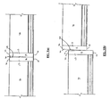
- reference numeral 10 generally designates a sideform moulding accessory, in accordance with an embodiment of the invention.
- the accessory 10 includes a cap member 12 for capping an end 14 ( Fig. 2(a) ) of a sideform 16.
- the cap member 12 has a pair of opposed sides 12.1 and 12.2 and a peripheral portion 13. At least a part of a profile 18 of the peripheral portion 13 complements a moulding surface 20 ( Fig. 2(a) ) of the sideform 16.
- the accessory 10 also includes a retaining member 22 which extends from the side 12.2 of the cap member 12 for retaining the cap member 12 in position relative to the end 14 of the sideform 16.
- the profile 18 of the peripheral portion 13 of the cap member 12 illustrated in Figs. 1(a) to 3(b) of the drawings is arranged to facilitate end-to-end abutment of a plurality of sideforms 16.
- the profile 18 defines a surface 24 having chamfered portions 26 configured so that the surface 24 matches the moulding surface 20 of the sideform 16. This allows a plurality of capped sideforms 16 to be arranged in end-to-end abutment to form a substantially uninterrupted, extended moulding surface 20.
- the side 12.1 of the cap member 12 also defines a bearing surface 28 ( Fig. 1(b) ).
- the bearing surface 28 of the cap member 12 associated with the first sideform 16 bears against the bearing surface 28 of the cap member 12 associated with the adjacent, second sideform 16.
- an operatively rear part 30 of the bearing surface 28 of each cap member 12 tapers inwardly towards an operatively rear edge 32 of the cap member 12 to facilitate removal of the sideforms 16 after use.
- a periphery 34 ( Fig. 1(a) ) of the retaining member 22 complements internal contours 36 of the sideform 16 so that, in use, the retaining member 22 is snugly received in the end 14 of the sideform 16 and inhibits the ingress of material into an interior 38 ( Fig. 2(a) ) of the sideform 16.
- the periphery 34 of the retaining member 22 is arranged inwardly of a periphery 40 of the cap member 12 so that an inner surface 42 of the cap member 12 defines a sealing surface arranged about the retaining member 22.
- the retaining member 22 is received in the end 14 of the sideform 16 with the inner surface 42 of the cap member 12 abutting the end 14 of the sideform 16.
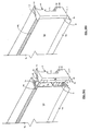
- Figs. 4(a) to 7(b) of the drawings another embodiment of the accessory 10 is shown.
- the cap member 12 is configured to facilitate abutment of sideforms 16 arranged transversely to each other.
- the bearing surface 28 of the cap member 12 of the capped sideform 16 abuts the moulding surface 20 of the other sideform 16 when a first capped sideform 16 is arranged transversely to a second sideform 16 to form a junction 43 ( Fig. 6 ).
- the profile 18 of the peripheral portion 13 of the cap member 12 complements the moulding surface 20 of the sideform 16 which the accessory 10 caps.
- the profile 18 has an associated surface 24 having chamfered portions 26 to match the moulding surface 20 of the capped sideform 16.
- the bearing surface 28 is also configured to complement the moulding surface 20 of the second sideform 16 against which the accessory 10 abuts.
- the bearing surface 28 has bevelled ends 44 ( Fig. 7(a) ) which bear against chamfered portions 46 ( Fig. 6 ) of the moulding surface 20 of the second sideform 16.
- the cap member 12 and the retaining member 22 are formed integrally with each other as a one piece unit.
- the accessory 10 is moulded of a resiliently flexible material, more particularly, an elastomeric material.
- the elastomeric material is a synthetic rubber.
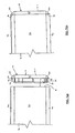
- a plurality of capped sideforms 16 capped with accessories 10 of the first embodiment are arranged in end-to-end abutment so that the associated bearing surfaces 28 of aligned cap members 12 abut against each other.
- these sideforms are used to form the longer sides of the mould.
- the flexibility of the material from which the accessory 10 is formed inhibits gaps forming between abutting parts of the bearing surfaces 28.
- the mould is completed by arranging further sideforms 16 transversely to those sideform 16 establishing the longer sides of the mould. Outer ends of each of the endmost sideforms 16 of the transversely arranged sideforms are capped with accessories 10 according to the second embodiment.
- the bearing surface 28 of each cap member 12 at the end of the relevant transversely arranged sideform 16 bears against the moulding surface 20 of the relevant longitudinally arranged sideform 16.
- the profile 18 of the peripheral portion 13 of the cap member 12 of the accessory 10 of the transversely arranged sideform 16 complements the moulding surface 20 of is associated sideform as well as the moulding surface 20 of the longitudinally arranged sideform 16 against which the transversely arranged sideform 16 abuts. Again, the flexibility of the accessory 10 inhibits gaps forming between the bearing surface 28 and the moulding surface 20with which the bearing surface 28 is in abutment.
- the rear part 30 of the bearing surface 28 is tapered such that when capped sideforms 16 are arranged in end-to-end abutment a V-shaped gap 48 is defined between aligned bearing surfaces 28. Accordingly, the area of contact between the bearing surfaces 28 is minimised.
- a settable concrete mixture is poured into the mould formed by the sideforms 16 and allowed to set to the shape defined by the sideforms 16.
- the sideforms 16 of the mould are removed.
- one end 14 of the sideform 16 is moved away from the panel as a first step to overcome any resistance to removal of the sideform 16.
- the end 14 passes through the gap 48 between the tapers 30 as the end 14 moves along an arc, the centre of rotation of which is located at the opposite end 14 of the sideform 16 being removed.
- the opposite end 14 is then moved away from the panel to complete removal of the sideform 16 from the panel. This also frees up the remainder of the sideforms 16 of the mould which facilitates removal of the remaining sideforms 16.
- sideforms 16 can be readily removed from a mould after a panel has set.
Landscapes
- Engineering & Computer Science (AREA)
- Architecture (AREA)
- Mechanical Engineering (AREA)
- Chemical & Material Sciences (AREA)
- Structural Engineering (AREA)
- Manufacturing & Machinery (AREA)
- Civil Engineering (AREA)
- Ceramic Engineering (AREA)
- Moulds, Cores, Or Mandrels (AREA)
- Footwear And Its Accessory, Manufacturing Method And Apparatuses (AREA)
- Closures For Containers (AREA)
- Orthopedics, Nursing, And Contraception (AREA)
- Manufacturing Of Tubular Articles Or Embedded Moulded Articles (AREA)
Claims (6)
- Seitenform-Gusszubehör (20), wobei das Zubehör (10) beinhaltet:ein Abschlussteil (12) zum Abschlieben eines Endes (14) einer Seitenform (16), wobei das Abschlussteil (12) ein Paar gegenüberliegender Seiten (12.1, 12.2) und einen Umfangsabschnitt (13) beinhaltet, wobei mindestens ein Teil des Profils (18) des Umfangsabschnitts (13) eine Gussoberfläche der Seitenform (16) ergänzt; undein Rückhalteteil (22), welches sich von einer der Seiten des Abschlussteils (12) zum Zurückhalten des Abschlussteils (12) in Position relativ zu dem Ende (14) der Seitenform (16) erstreckt, wobei die andere Seite des Abschlussteils (12) eine Lageroberfläche (28) definiert,wobei das Abschlussteil (12) und das Rückhalteteil (22) integral miteinander als eine Stückeinheit ausgebildet sind, unddadurch gekennzeichnet, dass entweder ein rückwärtiges Teil (30) der Lageroberfläche (28) dünner wird oder die Lageroberfläche (28) angeschrägte Enden (44) beinhaltet, unddie eine Stückeinheit ein Guss eines nachgiebigen flexiblen Materials ist.
- Zubehör (10) nach Anspruch 1, bei dem das Profil (18) des Umfangsabschnitts (13) des Abschlussteils (12) geformt ist, um es zu erlauben, eine Vielzahl von abgeschlossenen Seitenformen (16) Ende-an-Ende angrenzend anzuordnen.
- Zubehör (10) nach Anspruch 1, bei dem das Profil (18) des Umfangsabschnitts (13) des Abschlussteils (12) geformt ist, um es zu erlauben, eine Seitenform (16), die das Abschlussteil (12) an ihrem Ende (14) trägt, senkrecht zu und angrenzend an die Gussoberfläche einer weiteren Seitenform (16) anzuordnen.
- Zubehör (10) nach Anspruch 1, bei dem ein operatives rückwärtiges Teil (30) der Lageroberfläche (28) nach innen, hin zu einer operativen rückwärtigen Kante des Abschlussteils (12), dünner wird, um ein Entfernen der Seitenform nach Benutzung zu fördern.
- Zubehör (10) nach Anspruch 4, bei dem ein Umfang (34) des Rückhalteteils (22) innere Konturen der Seitenform (16) derart ergänzt, dass das Rückhalteteil (22) den Eintritt von Material in ein Inneres der Seitenform (16) während der Benutzung hemmt.
- Zubehör (10) nach einem der voranstehenden Ansprüche, bei dem der Umfang (34) des Rückhalteteils (22) innerhalb des Umfangsabschnitts (13) des Abschlussteils (12) angeordnet ist, um eine Dichtungsoberfläche um das Rückhalteteil (22) zu definieren.
Applications Claiming Priority (2)
| Application Number | Priority Date | Filing Date | Title |
|---|---|---|---|
| AU2006901830A AU2006901830A0 (en) | 2006-04-07 | A sideform end seal or cap | |
| PCT/AU2007/000397 WO2007115355A1 (en) | 2006-04-07 | 2007-03-28 | A sideform end seal or cap |
Publications (3)
| Publication Number | Publication Date |
|---|---|
| EP2010362A1 EP2010362A1 (de) | 2009-01-07 |
| EP2010362A4 EP2010362A4 (de) | 2009-07-15 |
| EP2010362B1 true EP2010362B1 (de) | 2012-11-07 |
Family
ID=38580626
Family Applications (1)
| Application Number | Title | Priority Date | Filing Date |
|---|---|---|---|
| EP07718644A Active EP2010362B1 (de) | 2006-04-07 | 2007-03-28 | Seitenformenddichtung oder -kappe |
Country Status (6)
| Country | Link |
|---|---|
| US (1) | US8496223B2 (de) |
| EP (1) | EP2010362B1 (de) |
| CN (1) | CN101443170B (de) |
| AU (1) | AU2007236537B2 (de) |
| NZ (1) | NZ572341A (de) |
| WO (1) | WO2007115355A1 (de) |
Families Citing this family (7)
| Publication number | Priority date | Publication date | Assignee | Title |
|---|---|---|---|---|
| RU2446261C2 (ru) * | 2006-11-14 | 2012-03-27 | ЭсАрБи КОНСТРАКШН ТЕКНОЛОДЖИЗ ПТИ ЛТД | Система боковой опалубки |
| US8782980B1 (en) * | 2012-11-09 | 2014-07-22 | Jose C. Fajardo | Protective device for covering the tip of a beam on which air conditioning equipment is installed |
| DE202013102579U1 (de) * | 2013-06-17 | 2013-07-15 | Robert Vollmayer | Schalungssystem |
| CN103866980B (zh) * | 2014-03-29 | 2016-04-27 | 二十二冶集团第一建设有限公司 | 墙体钢模板木制堵头板施工方法 |
| AT516800B1 (de) * | 2015-02-13 | 2017-07-15 | Progress Holding Ag | Schalungssystem zur Herstellung einer Schalung für ein Betonfertigteil |
| US10947746B2 (en) * | 2018-09-06 | 2021-03-16 | MW Panel Tech, LLC | Configurable steel form system for fabricating precast panels |
| CN110103322B (zh) * | 2019-06-06 | 2024-06-14 | 电联工程技术股份有限公司 | 一种可调节尺寸的预制叠合楼板组合模具 |
Citations (1)
| Publication number | Priority date | Publication date | Assignee | Title |
|---|---|---|---|---|
| US5015117A (en) * | 1987-02-06 | 1991-05-14 | Pawlicki Patrick S | Construction materials with end connectors |
Family Cites Families (13)
| Publication number | Priority date | Publication date | Assignee | Title |
|---|---|---|---|---|
| US3822858A (en) * | 1969-07-14 | 1974-07-09 | J Franklin | Spacer elements for corner forming system |
| US4042205A (en) * | 1975-12-08 | 1977-08-16 | Flavel Deloyd Herrell | Mold element for horizontally forming panels |
| US4557091A (en) * | 1982-02-10 | 1985-12-10 | Corflex International, Inc. | Extruded structural system |
| CA1271656A (fr) | 1987-04-06 | 1990-07-17 | Guy Ferland | Forme flexible pour bordure de rue et trottoir |
| DE4019498C1 (de) * | 1990-06-19 | 1991-07-25 | Paschal-Werk G. Maier Gmbh, 7619 Steinach, De | |
| AU661219B2 (en) * | 1993-03-16 | 1995-07-13 | Aluminium Extrusion And Distribution Pty Limited | Sealing abutting framing members |
| CN2386112Y (zh) * | 1999-06-14 | 2000-07-05 | 卓全利 | 易拆模板 |
| AUPR146500A0 (en) * | 2000-11-15 | 2000-12-07 | Tiltform Licensing Pty Ltd | Connectors for sideforms used in formwork for moulding concrete construction panels |
| US6712546B1 (en) * | 2001-08-08 | 2004-03-30 | John Radu, Jr. | Polymeric forms for moldable building material structures |
| WO2003040493A1 (en) * | 2001-11-07 | 2003-05-15 | Fukuvi Usa, Inc. | Bulkhead for forming concrete panels |
| AUPR984902A0 (en) * | 2002-01-08 | 2002-01-31 | Nicolo, Assunta | A device and system |
| US7284353B2 (en) * | 2002-11-05 | 2007-10-23 | Riverside Millwork Co., Inc. | Window and door casing |
| CA2566706C (en) * | 2004-05-24 | 2013-10-29 | Srb Construction Technologies Pty Ltd. | Concrete sideform system |
-
2007
- 2007-03-28 EP EP07718644A patent/EP2010362B1/de active Active
- 2007-03-28 CN CN2007800175894A patent/CN101443170B/zh active Active
- 2007-03-28 US US12/296,241 patent/US8496223B2/en active Active
- 2007-03-28 NZ NZ572341A patent/NZ572341A/en unknown
- 2007-03-28 WO PCT/AU2007/000397 patent/WO2007115355A1/en not_active Ceased
- 2007-03-28 AU AU2007236537A patent/AU2007236537B2/en active Active
Patent Citations (1)
| Publication number | Priority date | Publication date | Assignee | Title |
|---|---|---|---|---|
| US5015117A (en) * | 1987-02-06 | 1991-05-14 | Pawlicki Patrick S | Construction materials with end connectors |
Also Published As
| Publication number | Publication date |
|---|---|
| WO2007115355A1 (en) | 2007-10-18 |
| CN101443170B (zh) | 2012-07-04 |
| AU2007236537A1 (en) | 2007-10-18 |
| EP2010362A4 (de) | 2009-07-15 |
| AU2007236537B2 (en) | 2011-12-01 |
| CN101443170A (zh) | 2009-05-27 |
| US20100155571A1 (en) | 2010-06-24 |
| NZ572341A (en) | 2011-10-28 |
| US8496223B2 (en) | 2013-07-30 |
| EP2010362A1 (de) | 2009-01-07 |
Similar Documents
| Publication | Publication Date | Title |
|---|---|---|
| EP2010362B1 (de) | Seitenformenddichtung oder -kappe | |
| AU2017360985B2 (en) | Load transfer plate pocket and method of employing same | |
| AU2019216709B2 (en) | Joint edge assembly and method for forming joint in offset position | |
| US20100156000A1 (en) | Concrete block with beveled core opening edge | |
| US6893187B2 (en) | Expansion joint structure for concrete slabs | |
| KR101723334B1 (ko) | 절곡을 이용한 금속제 거푸집의 제작방법 및 그 방법에 의해 제조된 거푸집 | |
| US6226954B1 (en) | Process and apparatus for the splitting of cast concrete dual blocks | |
| KR101303047B1 (ko) | 절단설 제거 장치의 쉐어캡 및 고정 장치 | |
| JP2522636B2 (ja) | 筒状コンクリ―ト製品の製造方法 | |
| CN117449583B (zh) | 一种易拆模的预留孔洞支模结构及其使用方法 | |
| JP7625367B2 (ja) | 間知ブロック | |
| AU737849B2 (en) | Improvements relating to foundations or footings, suspended floors or ceilings | |
| CN207484976U (zh) | 一种室内地面高低差处阳角部位耐磨构件 | |
| KR200414668Y1 (ko) | 방호벽 균열유도돌조가 형성된 방호벽거푸집 | |
| CN206873304U (zh) | 一种桥梁防护墙模具组件 | |
| JP2628169B2 (ja) | 脆性舗装体の補修方法 | |
| JP2010270468A (ja) | 大断面梁用工区分け型枠の設置工法 | |
| JP2578606B2 (ja) | 脆性体表面の整形方法 | |
| KR20030057838A (ko) | 보차도 경계석 시공용 거푸집 | |
| JPS63295206A (ja) | Pc板先付け工法における目地形成方法 | |
| JPH0665448U (ja) | Alcパネル | |
| GB2360731A (en) | A method of producing porous concrete bodies | |
| JPH0460186B2 (de) |
Legal Events
| Date | Code | Title | Description |
|---|---|---|---|
| PUAI | Public reference made under article 153(3) epc to a published international application that has entered the european phase |
Free format text: ORIGINAL CODE: 0009012 |
|
| 17P | Request for examination filed |
Effective date: 20081107 |
|
| AK | Designated contracting states |
Kind code of ref document: A1 Designated state(s): AT BE BG CH CY CZ DE DK EE ES FI FR GB GR HU IE IS IT LI LT LU LV MC MT NL PL PT RO SE SI SK TR |
|
| AX | Request for extension of the european patent |
Extension state: AL BA HR MK RS |
|
| A4 | Supplementary search report drawn up and despatched |
Effective date: 20090617 |
|
| 17Q | First examination report despatched |
Effective date: 20100120 |
|
| RAP1 | Party data changed (applicant data changed or rights of an application transferred) |
Owner name: SRB CONSTRUCTION TECHNOLOGIES PTY LTD. |
|
| REG | Reference to a national code |
Ref country code: DE Ref legal event code: R079 Ref document number: 602007026534 Country of ref document: DE Free format text: PREVIOUS MAIN CLASS: B28B0007220000 Ipc: B28B0007000000 |
|
| RIC1 | Information provided on ipc code assigned before grant |
Ipc: E04G 17/00 20060101ALI20120405BHEP Ipc: E04G 13/00 20060101ALI20120405BHEP Ipc: B28B 7/02 20060101ALI20120405BHEP Ipc: B28B 7/00 20060101AFI20120405BHEP |
|
| RTI1 | Title (correction) |
Free format text: A SIDEFORM END SEAL OR CAP |
|
| GRAP | Despatch of communication of intention to grant a patent |
Free format text: ORIGINAL CODE: EPIDOSNIGR1 |
|
| RAX | Requested extension states of the european patent have changed |
Extension state: RS Payment date: 20081107 Extension state: HR Payment date: 20081107 |
|
| GRAS | Grant fee paid |
Free format text: ORIGINAL CODE: EPIDOSNIGR3 |
|
| GRAA | (expected) grant |
Free format text: ORIGINAL CODE: 0009210 |
|
| AK | Designated contracting states |
Kind code of ref document: B1 Designated state(s): AT BE BG CH CY CZ DE DK EE ES FI FR GB GR HU IE IS IT LI LT LU LV MC MT NL PL PT RO SE SI SK TR |
|
| AX | Request for extension of the european patent |
Extension state: HR RS |
|
| REG | Reference to a national code |
Ref country code: GB Ref legal event code: FG4D |
|
| REG | Reference to a national code |
Ref country code: AT Ref legal event code: REF Ref document number: 582794 Country of ref document: AT Kind code of ref document: T Effective date: 20121115 Ref country code: CH Ref legal event code: EP |
|
| REG | Reference to a national code |
Ref country code: IE Ref legal event code: FG4D |
|
| REG | Reference to a national code |
Ref country code: DE Ref legal event code: R096 Ref document number: 602007026534 Country of ref document: DE Effective date: 20130103 |
|
| REG | Reference to a national code |
Ref country code: AT Ref legal event code: MK05 Ref document number: 582794 Country of ref document: AT Kind code of ref document: T Effective date: 20121107 |
|
| REG | Reference to a national code |
Ref country code: NL Ref legal event code: T3 |
|
| REG | Reference to a national code |
Ref country code: LT Ref legal event code: MG4D |
|
| PG25 | Lapsed in a contracting state [announced via postgrant information from national office to epo] |
Ref country code: SE Free format text: LAPSE BECAUSE OF FAILURE TO SUBMIT A TRANSLATION OF THE DESCRIPTION OR TO PAY THE FEE WITHIN THE PRESCRIBED TIME-LIMIT Effective date: 20121107 Ref country code: FI Free format text: LAPSE BECAUSE OF FAILURE TO SUBMIT A TRANSLATION OF THE DESCRIPTION OR TO PAY THE FEE WITHIN THE PRESCRIBED TIME-LIMIT Effective date: 20121107 Ref country code: IS Free format text: LAPSE BECAUSE OF FAILURE TO SUBMIT A TRANSLATION OF THE DESCRIPTION OR TO PAY THE FEE WITHIN THE PRESCRIBED TIME-LIMIT Effective date: 20130307 Ref country code: LT Free format text: LAPSE BECAUSE OF FAILURE TO SUBMIT A TRANSLATION OF THE DESCRIPTION OR TO PAY THE FEE WITHIN THE PRESCRIBED TIME-LIMIT Effective date: 20121107 Ref country code: ES Free format text: LAPSE BECAUSE OF FAILURE TO SUBMIT A TRANSLATION OF THE DESCRIPTION OR TO PAY THE FEE WITHIN THE PRESCRIBED TIME-LIMIT Effective date: 20130218 |
|
| PG25 | Lapsed in a contracting state [announced via postgrant information from national office to epo] |
Ref country code: PL Free format text: LAPSE BECAUSE OF FAILURE TO SUBMIT A TRANSLATION OF THE DESCRIPTION OR TO PAY THE FEE WITHIN THE PRESCRIBED TIME-LIMIT Effective date: 20121107 Ref country code: BE Free format text: LAPSE BECAUSE OF FAILURE TO SUBMIT A TRANSLATION OF THE DESCRIPTION OR TO PAY THE FEE WITHIN THE PRESCRIBED TIME-LIMIT Effective date: 20121107 Ref country code: GR Free format text: LAPSE BECAUSE OF FAILURE TO SUBMIT A TRANSLATION OF THE DESCRIPTION OR TO PAY THE FEE WITHIN THE PRESCRIBED TIME-LIMIT Effective date: 20130208 Ref country code: CY Free format text: LAPSE BECAUSE OF FAILURE TO SUBMIT A TRANSLATION OF THE DESCRIPTION OR TO PAY THE FEE WITHIN THE PRESCRIBED TIME-LIMIT Effective date: 20121107 Ref country code: PT Free format text: LAPSE BECAUSE OF FAILURE TO SUBMIT A TRANSLATION OF THE DESCRIPTION OR TO PAY THE FEE WITHIN THE PRESCRIBED TIME-LIMIT Effective date: 20130307 Ref country code: SI Free format text: LAPSE BECAUSE OF FAILURE TO SUBMIT A TRANSLATION OF THE DESCRIPTION OR TO PAY THE FEE WITHIN THE PRESCRIBED TIME-LIMIT Effective date: 20121107 Ref country code: LV Free format text: LAPSE BECAUSE OF FAILURE TO SUBMIT A TRANSLATION OF THE DESCRIPTION OR TO PAY THE FEE WITHIN THE PRESCRIBED TIME-LIMIT Effective date: 20121107 |
|
| PG25 | Lapsed in a contracting state [announced via postgrant information from national office to epo] |
Ref country code: AT Free format text: LAPSE BECAUSE OF FAILURE TO SUBMIT A TRANSLATION OF THE DESCRIPTION OR TO PAY THE FEE WITHIN THE PRESCRIBED TIME-LIMIT Effective date: 20121107 |
|
| PG25 | Lapsed in a contracting state [announced via postgrant information from national office to epo] |
Ref country code: DK Free format text: LAPSE BECAUSE OF FAILURE TO SUBMIT A TRANSLATION OF THE DESCRIPTION OR TO PAY THE FEE WITHIN THE PRESCRIBED TIME-LIMIT Effective date: 20121107 Ref country code: BG Free format text: LAPSE BECAUSE OF FAILURE TO SUBMIT A TRANSLATION OF THE DESCRIPTION OR TO PAY THE FEE WITHIN THE PRESCRIBED TIME-LIMIT Effective date: 20130207 Ref country code: CZ Free format text: LAPSE BECAUSE OF FAILURE TO SUBMIT A TRANSLATION OF THE DESCRIPTION OR TO PAY THE FEE WITHIN THE PRESCRIBED TIME-LIMIT Effective date: 20121107 Ref country code: EE Free format text: LAPSE BECAUSE OF FAILURE TO SUBMIT A TRANSLATION OF THE DESCRIPTION OR TO PAY THE FEE WITHIN THE PRESCRIBED TIME-LIMIT Effective date: 20121107 Ref country code: SK Free format text: LAPSE BECAUSE OF FAILURE TO SUBMIT A TRANSLATION OF THE DESCRIPTION OR TO PAY THE FEE WITHIN THE PRESCRIBED TIME-LIMIT Effective date: 20121107 |
|
| PG25 | Lapsed in a contracting state [announced via postgrant information from national office to epo] |
Ref country code: RO Free format text: LAPSE BECAUSE OF FAILURE TO SUBMIT A TRANSLATION OF THE DESCRIPTION OR TO PAY THE FEE WITHIN THE PRESCRIBED TIME-LIMIT Effective date: 20121107 |
|
| PLBE | No opposition filed within time limit |
Free format text: ORIGINAL CODE: 0009261 |
|
| STAA | Information on the status of an ep patent application or granted ep patent |
Free format text: STATUS: NO OPPOSITION FILED WITHIN TIME LIMIT |
|
| 26N | No opposition filed |
Effective date: 20130808 |
|
| PG25 | Lapsed in a contracting state [announced via postgrant information from national office to epo] |
Ref country code: MC Free format text: LAPSE BECAUSE OF NON-PAYMENT OF DUE FEES Effective date: 20130331 |
|
| REG | Reference to a national code |
Ref country code: CH Ref legal event code: PL |
|
| REG | Reference to a national code |
Ref country code: DE Ref legal event code: R097 Ref document number: 602007026534 Country of ref document: DE Effective date: 20130808 |
|
| REG | Reference to a national code |
Ref country code: IE Ref legal event code: MM4A |
|
| PG25 | Lapsed in a contracting state [announced via postgrant information from national office to epo] |
Ref country code: CH Free format text: LAPSE BECAUSE OF NON-PAYMENT OF DUE FEES Effective date: 20130331 Ref country code: LI Free format text: LAPSE BECAUSE OF NON-PAYMENT OF DUE FEES Effective date: 20130331 Ref country code: IE Free format text: LAPSE BECAUSE OF NON-PAYMENT OF DUE FEES Effective date: 20130328 |
|
| PGFP | Annual fee paid to national office [announced via postgrant information from national office to epo] |
Ref country code: TR Payment date: 20140324 Year of fee payment: 8 |
|
| PG25 | Lapsed in a contracting state [announced via postgrant information from national office to epo] |
Ref country code: MT Free format text: LAPSE BECAUSE OF FAILURE TO SUBMIT A TRANSLATION OF THE DESCRIPTION OR TO PAY THE FEE WITHIN THE PRESCRIBED TIME-LIMIT Effective date: 20121107 |
|
| PG25 | Lapsed in a contracting state [announced via postgrant information from national office to epo] |
Ref country code: HU Free format text: LAPSE BECAUSE OF FAILURE TO SUBMIT A TRANSLATION OF THE DESCRIPTION OR TO PAY THE FEE WITHIN THE PRESCRIBED TIME-LIMIT; INVALID AB INITIO Effective date: 20070328 Ref country code: LU Free format text: LAPSE BECAUSE OF NON-PAYMENT OF DUE FEES Effective date: 20130328 |
|
| REG | Reference to a national code |
Ref country code: FR Ref legal event code: PLFP Year of fee payment: 9 |
|
| PGFP | Annual fee paid to national office [announced via postgrant information from national office to epo] |
Ref country code: DE Payment date: 20150922 Year of fee payment: 9 Ref country code: GB Payment date: 20150917 Year of fee payment: 9 |
|
| PGFP | Annual fee paid to national office [announced via postgrant information from national office to epo] |
Ref country code: IT Payment date: 20150928 Year of fee payment: 9 |
|
| PGFP | Annual fee paid to national office [announced via postgrant information from national office to epo] |
Ref country code: FR Payment date: 20150930 Year of fee payment: 9 Ref country code: NL Payment date: 20151005 Year of fee payment: 9 |
|
| REG | Reference to a national code |
Ref country code: DE Ref legal event code: R119 Ref document number: 602007026534 Country of ref document: DE |
|
| REG | Reference to a national code |
Ref country code: NL Ref legal event code: MM Effective date: 20160401 |
|
| GBPC | Gb: european patent ceased through non-payment of renewal fee |
Effective date: 20160328 |
|
| REG | Reference to a national code |
Ref country code: FR Ref legal event code: ST Effective date: 20161130 |
|
| PG25 | Lapsed in a contracting state [announced via postgrant information from national office to epo] |
Ref country code: NL Free format text: LAPSE BECAUSE OF NON-PAYMENT OF DUE FEES Effective date: 20160401 Ref country code: GB Free format text: LAPSE BECAUSE OF NON-PAYMENT OF DUE FEES Effective date: 20160328 Ref country code: DE Free format text: LAPSE BECAUSE OF NON-PAYMENT OF DUE FEES Effective date: 20161001 Ref country code: FR Free format text: LAPSE BECAUSE OF NON-PAYMENT OF DUE FEES Effective date: 20160331 |
|
| PG25 | Lapsed in a contracting state [announced via postgrant information from national office to epo] |
Ref country code: IT Free format text: LAPSE BECAUSE OF NON-PAYMENT OF DUE FEES Effective date: 20160328 |
|
| PG25 | Lapsed in a contracting state [announced via postgrant information from national office to epo] |
Ref country code: TR Free format text: LAPSE BECAUSE OF NON-PAYMENT OF DUE FEES Effective date: 20160328 |