EP2010302B1 - Filterelement - Google Patents
Filterelement Download PDFInfo
- Publication number
- EP2010302B1 EP2010302B1 EP06819940A EP06819940A EP2010302B1 EP 2010302 B1 EP2010302 B1 EP 2010302B1 EP 06819940 A EP06819940 A EP 06819940A EP 06819940 A EP06819940 A EP 06819940A EP 2010302 B1 EP2010302 B1 EP 2010302B1
- Authority
- EP
- European Patent Office
- Prior art keywords
- plastic
- filter medium
- filter element
- plastic part
- potting compound
- Prior art date
- Legal status (The legal status is an assumption and is not a legal conclusion. Google has not performed a legal analysis and makes no representation as to the accuracy of the status listed.)
- Active
Links
Images


Classifications
-
- B—PERFORMING OPERATIONS; TRANSPORTING
- B01—PHYSICAL OR CHEMICAL PROCESSES OR APPARATUS IN GENERAL
- B01D—SEPARATION
- B01D29/00—Filters with filtering elements stationary during filtration, e.g. pressure or suction filters, not covered by groups B01D24/00 - B01D27/00; Filtering elements therefor
- B01D29/11—Filters with filtering elements stationary during filtration, e.g. pressure or suction filters, not covered by groups B01D24/00 - B01D27/00; Filtering elements therefor with bag, cage, hose, tube, sleeve or like filtering elements
- B01D29/13—Supported filter elements
-
- B—PERFORMING OPERATIONS; TRANSPORTING
- B01—PHYSICAL OR CHEMICAL PROCESSES OR APPARATUS IN GENERAL
- B01D—SEPARATION
- B01D46/00—Filters or filtering processes specially modified for separating dispersed particles from gases or vapours
- B01D46/24—Particle separators, e.g. dust precipitators, using rigid hollow filter bodies
- B01D46/2403—Particle separators, e.g. dust precipitators, using rigid hollow filter bodies characterised by the physical shape or structure of the filtering element
- B01D46/2411—Filter cartridges
- B01D46/2414—End caps including additional functions or special forms
-
- B—PERFORMING OPERATIONS; TRANSPORTING
- B01—PHYSICAL OR CHEMICAL PROCESSES OR APPARATUS IN GENERAL
- B01D—SEPARATION
- B01D2201/00—Details relating to filtering apparatus
- B01D2201/29—Filter cartridge constructions
- B01D2201/291—End caps
-
- B—PERFORMING OPERATIONS; TRANSPORTING
- B01—PHYSICAL OR CHEMICAL PROCESSES OR APPARATUS IN GENERAL
- B01D—SEPARATION
- B01D2201/00—Details relating to filtering apparatus
- B01D2201/40—Special measures for connecting different parts of the filter
-
- B—PERFORMING OPERATIONS; TRANSPORTING
- B01—PHYSICAL OR CHEMICAL PROCESSES OR APPARATUS IN GENERAL
- B01D—SEPARATION
- B01D2265/00—Casings, housings or mounting for filters specially adapted for separating dispersed particles from gases or vapours
- B01D2265/04—Permanent measures for connecting different parts of the filter, e.g. welding, glueing or moulding
-
- B—PERFORMING OPERATIONS; TRANSPORTING
- B01—PHYSICAL OR CHEMICAL PROCESSES OR APPARATUS IN GENERAL
- B01D—SEPARATION
- B01D2265/00—Casings, housings or mounting for filters specially adapted for separating dispersed particles from gases or vapours
- B01D2265/06—Details of supporting structures for filtering material, e.g. cores
Definitions
- the invention relates to a filter element according to the preamble of claim 1.
- a filter cell which has a filter insert arranged in a frame, wherein the ends of the filter web are fixed by means of a potting compound on the frame and wherein between the frame and potting compound a self-adhesive separating web is arranged.
- filter elements which have plastic end discs and filter media. Between the plastic end disks and the filter medium, a sealing compound is produced by means of a PUR potting compound (polyurethane potting compound).
- the filter element additionally has a support tube made of plastic, which is also sealed by the potting compound with the filter medium.
- the PUR potting compound may be affected by factors such as Aging of the PUR potting compound, temperature fluctuations or vibrations, loose from the plastic parts, resulting in leaks.
- the object of the invention is therefore to provide a filter element which has a permanently sealing connection between the plastic parts and the filter medium. This object is solved by the features of claim 1.
- the filter element according to the invention is provided for the purification of a fluid.
- the fluid may be gaseous or liquid.
- the filter element for cleaning intake air of an internal combustion engine intended.
- the filter element may be formed as a flat element or as a ring-shaped closed filter element.
- the filter element has at least one plastic part and a filter medium which is suitable for the separation of impurities from the fluid stream. Any of the filter media known in the prior art can be used here.
- the plastic part may consist of a duroplastic, or an elastomer, or a thermoplastic. On the plastic part, a connecting part is arranged, which is permanently connected to the plastic part.
- the connecting part may be glued to the plastic part, welded or cast, at least parts of the connecting part protrude beyond the plastic part.
- the connecting part which consists for example of a plastic foam, a cellulose paper or a non-woven fabric, has a porous structure. This porous structure may have holes, channels or spaces in which a potting compound can penetrate.
- the potting compound may preferably consist of a polyurethane or any casting resin.
- the potting compound contacts on the one hand the plastic part in the region of the connecting part and on the other hand the filter medium.
- the potting compound thus forms a sealing connection between the plastic part and the filter medium, the potting compound parts, in particular end plates of a Round filter element, can form. Due to the penetration of the potting compound in the connecting part, after the solidification of the potting compound, a permanently solid composite is formed, which forms a sealing connection between the plastic part and the potting compound and thus with the filter medium.
- the connecting part is a fleece part, which has a fleece area, which projects beyond the plastic part, and a connecting area, which is fixedly connected to the plastic part.
- the fleece part is preferably a plastic fleece, which consists of numerous individual fibers and thus forms the fleece area.
- the connection area may e.g. be formed of compressed fibers which are glued or welded to the plastic part.
- the connecting region of the connecting part can also protrude into the plastic part and thus form the permanent connection.
- the Velcro area is designed such that on the one hand there are sufficient gaps between the fibers into which the potting compound can penetrate, and on the other hand the fibers themselves have sufficient stability, whereby detachment of the potting compound from the plastic part is prevented.
- the plastic part consists of a thermoplastic material, wherein the plastic part is produced by injection molding.
- the connecting part is called prefabricated component inserted into the injection mold of the plastic part and then the plastic melt is injected into the injection mold.
- the plastic melt partially penetrates into the connecting part and thus forms a permanent connection.
- the connecting part melts in the contact area with the melt and thus forms a permanent bond with the solidified plastic melt.
- the plastic part is a plastic end of a round filter element, wherein the filter medium is closed annularly.
- the filter medium is closed annularly.
- the plastic end disk is arranged on the front side of the filter medium.
- the connecting part is arranged in the region of the plastic end disk facing the filter medium.
- the connecting part is annular in this embodiment, wherein the connecting part extends over the entire region of the plastic end disc, which corresponds to the filter medium.
- the plastic part is a support tube, which is arranged in a round filter element.
- the support tube is provided for mechanical stabilization of the filter medium and designed to be permeable to the fluid to be cleaned.
- this is supported by the outer circumference of the support tube.
- the support tube encloses the filter medium
- the filter medium is supported by the inner surface of the support body.
- the support tube has end faces which correspond with end plates. In this case, the end discs of any material, such. Plastic, metal, rubber or the potting compound itself, be formed.
- the connecting part is arranged on the support tube.
- the connecting part may be arranged on the outer circumference, the inner surface or on the front-side annular surface.
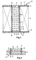
- FIG. 1 a filter element 10 is shown in section.
- the filter element 10 has an upper end plate 11 and a lower end plate 12, wherein the end plates 11, 12 are made of polyamide.
- the upper end disk 11 has an opening 13 through which the fluid to be cleaned or the already cleaned fluid can flow.
- the lower end plate 12 is executed closed.
- Both end disks 11, 12 have an outer pouring rim 14 and an inner pouring rim 15.
- the pouring edges 14, 15 form an annular pouring cup 16 at each end disc 11, 12.
- a fleece ring 17 which is inseparable from the respective one End plate 11, 12 is connected.
- Between the end plates 11, 12 extends a folded, annular closed filter medium 18.
- the filter medium 18 projects into the casting shells 16 of the end plates 11, 12 into it.
- a Potting compound 19 is provided which on the one hand surrounds the filter medium 18 on the front side and on the other hand passes through the fleece ring 17.
- FIG. 2 is the lower end plate 12 according to FIG. 1 in a perspective view in section, wherein a section A in the FIG. 2a is shown enlarged.
- the fleece ring 17 has a fleece region 20 and a connecting region 21.
- the fleece region 20 projects from the end disk 12 into the casting shell 16.
- the Velcro region 20 is formed by loosely abutting fibers 22.
- the connecting region 21 is formed by fibers 22 embedded in the plastic of the end disk 12.
- the fleece ring 17 and the upper end plate 11 are connected in the same way.
- FIG. 3 an alternative ausgestaltetes filter element 10 'is shown in section.
- the filter element 10 ' has a zigzag-shaped folded and annularly closed filter medium 18, which is arranged between two end plates 11' and 12 '.
- a support tube 24 is arranged in the, formed by the filter medium 18 cavity 23, a support tube 24 is arranged.
- the support tube 24 is made of plastic and has Passages 25 through which the fluid can flow.
- the support tube 24 has an outer circumference 26, an inner surface 27 and end faces 28.
- the support tube 24 is enclosed in the region of the end faces 28 of the potting compound 19.
- the end plates 11 'and 12' are formed by the potting compound 19.
- the geometric outer dimensions of the end plates 11 'and 12' are formed by a tool mold (not shown), in which the liquid potting compound 19 is filled and removed after solidification as an end plate.
- a tool mold (not shown), in which the liquid potting compound 19 is filled and removed after solidification as an end plate.
- a non-woven ring 17 is formed according to a reference to the FIGS. 4 to 6 described embodiments provided.
- FIG. 4 is a section of the filter element 10 'according to FIG. 3 shown. Of the FIG. 3 corresponding components are provided with the same reference numerals.
- the fleece ring 17 is arranged in the region of the end face 28 on the outer circumference 26.
- the fleece ring 17 is, as in FIG. 2a described, connected to the support tube 24.
- the potting compound 19 surrounds the frontal region of the support tube 24, wherein also the fleece ring 17 is enclosed.
- the outer periphery of the support body 24 is permanently connected to the potting compound 19, wherein this compound is sealing.
- FIG. 5 is an alternative to the one in FIG. 4 shown solution shown. Identical parts are provided with the same reference numerals.
- the fleece ring 17 is applied to the end face 28 of the support tube 24. in this connection corresponds to the connection of the nonwoven ring 17 with the support body 24 also in FIG. 2a described compound.
- FIG. 6 is another alternative to the in FIG. 4 and 5 shown embodiment shown. Identical parts are provided with the same reference numerals.
- the non-woven ring 17 is applied to the inner surface 27 of the support tube 24.
Landscapes
- Chemical & Material Sciences (AREA)
- Chemical Kinetics & Catalysis (AREA)
- Physics & Mathematics (AREA)
- Geometry (AREA)
- Filtering Of Dispersed Particles In Gases (AREA)
- Filtering Materials (AREA)
Abstract
Description
- Die Erfindung betrifft ein Filterelement nach dem Oberbegriff des Anspruches 1.
- Aus der
DE 4 324 388 C1 ist eine Filterzelle bekannt, die einen in einem Rahmen angeordneten Filtereinsatz aufweist, wobei die Enden der Filterbahn mittels einer Vergussmasse am Rahmen fixiert sind und wobei zwischen Rahmen und Vergussmasse eine selbstklebende Trennbahn angeordnet ist. - Es sind ferner Filterelemente bekannt, welche über Kunststoffendscheiben und Filtermedien verfügen. Zwischen den Kunststoffendscheiben und dem Filtermedium ist mittels einer PUR-Vergussmasse (Polyurethan-Vergussmasse) eine dichtende Verbindung erzeugt. Bei anderen Ausgestaltungen verfügt das Filterelement zusätzlich über ein Stützrohr aus Kunststoff, welches ebenfalls durch die Vergussmasse mit dem Filtermedium dichtend verbunden ist. Die PUR-Vergussmasse kann sich jedoch durch Einflussfaktoren, wie z.B. Alterung der PUR-Vergussmasse, Temperaturschwankungen oder Vibrationen, von den Kunststoffteilen lösen, was zu Undichtigkeiten führt.
- Aufgabe der Erfindung ist es daher, ein Filterelement zu schaffen, welches über eine dauerhaft dichtende Verbindung zwischen den Kunststoffteilen und dem Filtermedium verfügt. Diese Aufgabe wird durch die Merkmale des Anspruches 1 gelöst.
- Das erfindungsgemäße Filterelement ist zur Reinigung eines Fluids vorgesehen. Das Fluid kann gasförmig oder flüssig sein. Vorzugsweise ist das Filterelement zur Reinigung von Ansaugluft einer Brennkraftmaschine vorgesehen. Hierbei kann das Filterelement als Flachelement oder als ringförmig geschlossenes Filterelement ausgebildet sein. Das Filterelement verfügt zumindest über ein Kunststoffteil und ein Filtermedium, welches zur Abscheidung von Verunreinigungen aus dem Fluidstrom geeignet ist. Hierbei können alle beliebigen im Stand der Technik bekannten Filtermedien verwendet werden. Das Kunststoffteil kann aus einem Duroplast, oder einem Elastomer, oder einem Thermoplast bestehen. An dem Kunststoffteil ist ein Verbindungsteil angeordnet, welches unlösbar mit dem Kunststoffteil verbunden ist. Hierbei kann das Verbindungsteil an das Kunststoffteil angeklebt, angeschweißt oder eingegossen sein, wobei zumindest Teile des Verbindungsteils über das Kunststoffteil hinausragen. Das Verbindungsteil, welches z.B. aus einem Kunststoffschaum, einem Zellulosepapier oder einem Faservlies besteht, verfügt über eine poröse Struktur. Diese poröse Struktur kann Löcher, Kanäle oder Zwischenräume aufweisen, in welche eine Vergussmasse eindringen kann. Hierbei kann die Vergussmasse vorzugsweise aus einem Polyurethan oder einem beliebigen Gießharz bestehen Die Vergussmasse kontaktiert einerseits das Kunststoffteil im Bereich des Verbindungsteils und andererseits das Filtermedium. Die Vergussmasse bildet so eine dichtende Verbindung zwischen dem Kunststoffteil und dem Filtermedium, wobei die Vergussmasse Teile, insbesondere Endscheiben eines Rundfilterelementes, bilden kann. Durch das Eindringen der Vergussmasse in das Verbindungsteil, ist nach dem Erstarren der Vergussmasse ein dauerhaft fester Verbund gebildet, welcher eine dichtende Verbindung zwischen dem Kunststoffteil und der Vergussmasse und somit mit dem Filtermedium bildet.
- Erfindungsgemäß ist das Verbindungsteil ein Vliesteil, welches über einen Flauschbereich, welcher das Kunststoffteil überragt, und einen Verbindungsbereich, welcher mit dem Kunststoffteil fest verbunden ist, verfügt. Das Vliesteil ist vorzugsweise ein Kunststoffvlies, welches aus zahlreichen einzelnen Fasern besteht und so den Flauschbereich bildet. Der Verbindungsbereich kann z.B. aus verpressten Fasern, welche an das Kunststoffteil angeklebt oder angeschweißt sind gebildet sein. Weiterhin kann der Verbindungsbereich des Verbindungsteils auch in das Kunststoffteil hineinragen und so die unlösbare Verbindung bilden. Der Flauschbereich ist derart gestaltet, dass einerseits ausreichend Zwischenräume zwischen den Fasern vorhanden sind, in welche die Vergussmasse eindringen kann, und andererseits die Fasern selbst eine ausreichende Stabilität aufweise, wodurch ein Ablösen der Vergussmasse von dem Kunststoffteil verhindert wird.
- Erfindungsgemäß besteht das Kunststoffteil aus einem thermoplastischen Kunststoff, wobei das Kunststoffteil im Spritzgussverfahren hergestellt ist. Das Verbindungsteil wird als vorgefertigtes Bauteil in die Spritzgussform des Kunststoffteils eingelegt und anschließend wird die Kunststoffschmelze in die Spritzgussform eingespritzt. Die Kunststoffschmelze dringt teilweise in das Verbindungsteil ein und bildet so eine unlösbare Verbindung. Bei anderen Varianten schmilzt das Verbindungsteil im Kontaktbereich mit der Schmelze auf und bildet so mit der erstarrten Kunststoffschmelze eine unlösbare Verbindung. Das Anspritzen des Kunststoffteils an das Verbindungsteil ist ein einfaches und kostengünstiges Verfahren.
- Bei einer vorteilhaften Ausgestaltung ist das Kunststoffteil eine Kunststoffendscheibe eines Rundfilterelementes, wobei das Filtermedium ringförmig geschlossen ist. Unter " ringförmig geschlossen" im Sinne dieser Anmeldung ist neben dem kreisringförmigen Schließen des gefalteten Filtermediums auch ein beliebiges Bilden einer Hohlform, insbesondere oval oder polygon-förmig, zu verstehen. Die Kunststoffendscheibe ist auf der Stirnseite des Filtermediums angeordnet. Das Verbindungsteil ist in dem, dem Filtermedium zugewandten Bereich der Kunststoffendscheibe angeordnet. Das Verbindungsteil ist bei dieser Ausgestaltung ringförmig ausgebildet, wobei das Verbindungsteil sich über den gesamten Bereich der Kunststoffendscheibe erstreckt, welcher mit dem Filtermedium korrespondiert. Somit ist eine zuverlässig dichtende Verbindung zwischen dem Filtermedium und der Kunststoffendscheibe gewährleistet.
- Bei einer alternativen Ausgestaltung ist das Kunststoffteil ein Stützrohr, welches in einem Rundfilterelement angeordnet ist. Das Stützrohr ist zur mechanischen Stabilisierung des Filtermediums vorgesehen und für das zu reinigende Fluid durchlässig ausgebildet. Bei einer Anordnung des Stützrohres in dem ringförmig geschlossenen Filtermedium wird dieses durch den Außenumfang des Stützrohres gestützt. Bei einer Anordnung, bei welcher das Stützrohr das Filtermedium umschließt, wird das Filtermedium durch die Innenfläche des Stützkörpers abgestützt. Das Stützrohr verfügt über Stirnseiten, welche mit Endscheiben korrespondieren. Hierbei können die Endscheiben aus einem beliebigen Material, wie z.B. Kunststoff, Metall, Kautschuk oder der Vergussmasse selbst, gebildet sein. Im Bereich der Stirnseiten ist das Verbindungsteil auf dem Stützrohr angeordnet. Hierbei kann das Verbindungsteil auf dem Außenumfang, der Innenfläche oder auf der stirnseitigen Ringfläche angeordnet sein. Durch das Aufbringen der Vergussmasse auf das Stützrohr ist ein unlösbarer dichtender Verbund zwischen der Vergussmasse und dem Stützrohr gebildet. Sofern die Endscheibe durch die Vergussmasse gebildet ist, besteht ein dichtender Verbund zwischen der Endscheibe, dem Stützrohr und dem Filtermedium, welches ebenfalls von der Vergussmasse umschlossen ist.
- Weitere Einzelheiten der Erfindung werden nachfolgend anhand der schematischen Ausführungsbeispiele erläutert. Hierbei zeigt:
- Figur 1
- ein Filterelement im Schnitt,
- Figur 2
- eine Endscheibe im Schnitt,
- Figur 3
- ein alternativ ausgestaltetes Filterelement im Schnitt,
- Figur 4
- einen Ausschnitt eines Stützrohres im Schnitt,
- Figur 5
- eine alternative Ausgestaltung des Stützrohres im Schnitt und
- Figur 6
- eine weitere Alternative des Stützrohres im Schnitt.
- In
Figur 1 ist ein Filterelement 10 im Schnitt dargestellt. Das Filterelement 10 verfügt über eine obere Endscheibe 11 und eine untere Endscheibe 12, wobei die Endscheiben 11, 12 aus Polyamid bestehen. Die obere Endscheibe 11 verfügt über eine Öffnung 13, durch welche das zu reinigende oder das bereits gereinigte Fluid hindurch strömen kann. Die untere Endscheibe 12 ist geschlossen ausgeführt. Beide Endscheiben 11, 12 verfügen über einen äußeren Gießrand 14 und einen inneren Gießrand 15. Die Gießränder 14, 15 bilden bei jeder Endscheibe 11, 12 eine ringförmige Gießschale 16. In jeder Gießschale 16 ist jeweils ein Vliesring 17 angeordnet, welcher unlösbar mit der jeweiligen Endscheibe 11, 12 verbunden ist. Zwischen den Endscheiben 11, 12 erstreckt sich ein gefaltetes, ringförmig geschlossenes Filtermedium 18. Das Filtermedium 18 ragt in die Gießschalen 16 der Endscheiben 11, 12 hinein. Zum Fixieren des Filtermediums 18 in den Gießschalen 16 der Endscheiben 11, 12 ist eine Vergussmasse 19 vorgesehen, welche einerseits das Filtermedium 18 stirnseitig umschließt und andererseits den Vliesring 17 durchsetzt. Somit ist ein unlösbarer, dichtender Verbund zwischen den Endscheiben 11, 12 und dem Filtermedium geschaffen, welcher auch durch äußere Einflüsse, wie Erschütterungen oder Temperaturschwankungen nicht gelöst werden kann. - In
Figur 2 ist die untere Endscheibe 12 gemäßFigur 1 in perspektivischer Darstellung im Schnitt dargestellt, wobei ein Ausschnitt A in derFigur 2a vergrößert dargestellt ist. DerFigur 1 entsprechende Bauteile sind mit gleichen Bezugszeichen versehen. Der Vliesring 17 verfügt über einen Flauschbereich 20 und einen Verbindungsbereich 21. Der Flauschbereich 20 ragt von der Endscheibe 12 in die Gießschale 16 hinein. Hierbei wird der Flauschbereich 20 durch locker aneinander anliegende Fasern 22 gebildet. Der Verbindungsbereich 21 ist durch in den Kunststoff der Endscheibe 12 eingebettete Fasern 22 gebildet. Somit ist die Verbindung zwischen der Endscheibe 12 und dem Vliesring 17 unlösbar. Der Vliesring 17 und die obere Endscheibe 11 sind in gleicher Weise verbunden. - In
Figur 3 ist ein alternativ ausgestaltetes Filterelement 10' im Schnitt dargestellt. DerFigur 1 entsprechende Bauteile sind mit gleichen Bezugszeichen versehen. Das Filterelement 10' verfügt über ein zick-zack-förmig gefaltetes und ringförmig geschlossenes Filtermedium 18, welches zwischen zwei Endscheiben 11' und 12' angeordnet ist. In dem, durch das Filtermedium 18 gebildeten Hohlraum 23 ist ein Stützrohr 24 angeordnet. Das Stützrohr 24 besteht aus Kunststoff und verfügt über Durchlässe 25, durch welche das Fluid hindurch strömen kann. Weiterhin verfügt das Stützrohr 24 über einen Außenumfang 26, eine Innenfläche 27 und Stirnseiten 28. Das Stützrohr 24 ist im Bereich der Stirnseiten 28 von der Vergussmasse 19 umschlossen. Bei diesem Ausführungsbeispiel sind die Endscheiben 11' und 12' durch die Vergussmasse 19 gebildet. Die geometrischen Außenabmessungen der Endscheiben 11' und 12' werden durch eine Werkzeugform (nicht dargestellt) gebildet, in welche die flüssige Vergussmasse 19 eingefüllt und nach dem Erstarren als Endscheibe entnommen wird. Zur Bildung einer unlösbaren Verbindung zwischen dem Stützrohr 24 und der Vergussmasse 19 ist ein Vliesring 17 gemäß einer anhand derFiguren 4 bis 6 beschrieben Ausführungen vorgesehen. - In
Figur 4 ist ein Ausschnitt aus dem Filterelement 10' gemäßFigur 3 dargestellt. DerFigur 3 entsprechende Bauteile sind mit gleichen Bezugszeichen versehen. Der Vliesring 17 ist im Bereich der Stirnseite 28 am Außenumfang 26 angeordnet. Der Vliesring 17 ist, wie inFigur 2a beschrieben, mit dem Stützrohr 24 verbunden. Die Vergussmasse 19 umschließt den stirnseitigen Bereich des Stützrohres 24, wobei ebenfalls der Vliesring 17 umschlossen ist. Somit ist der Außenumfang des Stützkörpers 24 unlösbar mit der Vergussmasse 19 verbunden, wobei diese Verbindung dichtend ist. - In
Figur 5 ist eine Alternative zu der inFigur 4 dargestellten Lösung gezeigt. Gleiche Teile sind mit gleichen Bezugszeichen versehen. Bei dieser Alternative ist der Vliesring 17 auf die Stirnseite 28 des Stützrohres 24 aufgebracht. Hierbei entspricht die Verbindung des Vliesringes 17 mit dem Stützkörper 24ebenfalls der inFigur 2a beschriebenen Verbindung. - In
Figur 6 ist eine weitere Alternative zu den inFigur 4 und5 gezeigten Ausführung dargestellt. Gleiche Teile sind mit gleichen Bezugszeichen versehen. Bei diesem Ausführungsbeispiel ist der Vliesring 17 auf die Innenfläche 27 des Stützrohres 24 aufgebracht.
Claims (3)
- Filterelement (10) aufweisend zumindest ein Kunststoffteil (11, 12, 24), ein Filtermedium (18) und eine Vergussmasse (19), wobei die Vergussmasse (19) zur Bildung einer Verbindung zwischen dem Kunststoffteil(11, 12, 24) und dem Filtermedium (18) vorgesehen ist, wobei ein Verbindungsteil vorgesehen ist, welches fest mit dem Kunststoffteil (11, 12, 24) verbunden ist dadurch gekennzeichnet, dass das Verbindungsteil ein Vliesteil (17) ist, welches über einen Flauschbereich (20) und einen Verbindungsbereich (21) verfügt und die Vergussmasse (19) zumindest teilweise in das Vliesteil (17) eindringt und das Kunststoffteil (11, 12, 24) im Spritzgussverfahren hergestellt ist, wobei das Kunststoffteil (11, 12, 24) an das Verbindungsteil angespritzt ist.
- Filterelement nach Anspruch 1, dadurch gekennzeichnet, dass das Kunststoffteil (11, 12, 24) eine Endscheibe (11), (12) ist und das Verbindungsteil im Kontaktbereich zu dem Filtermedium (18) angeordnet ist.
- Filterelement nach Anspruch 1, dadurch gekennzeichnet, dass das Kunststoffteil (11, 12, 24) ein Stützrohr (24) mit einem Außenumfang (26) und zwei Stirnseiten (28) ist, wobei das Verbindungsteil im Bereich der Stirnseiten (28) angeordnet ist.
Applications Claiming Priority (2)
| Application Number | Priority Date | Filing Date | Title |
|---|---|---|---|
| DE202005020260U DE202005020260U1 (de) | 2005-12-23 | 2005-12-23 | Filterelement |
| PCT/EP2006/069565 WO2007074050A1 (de) | 2005-12-23 | 2006-12-12 | Filterelement |
Publications (2)
| Publication Number | Publication Date |
|---|---|
| EP2010302A1 EP2010302A1 (de) | 2009-01-07 |
| EP2010302B1 true EP2010302B1 (de) | 2010-11-10 |
Family
ID=37714547
Family Applications (1)
| Application Number | Title | Priority Date | Filing Date |
|---|---|---|---|
| EP06819940A Active EP2010302B1 (de) | 2005-12-23 | 2006-12-12 | Filterelement |
Country Status (5)
| Country | Link |
|---|---|
| US (1) | US8087517B2 (de) |
| EP (1) | EP2010302B1 (de) |
| CN (1) | CN101346170B (de) |
| DE (2) | DE202005020260U1 (de) |
| WO (1) | WO2007074050A1 (de) |
Families Citing this family (4)
| Publication number | Priority date | Publication date | Assignee | Title |
|---|---|---|---|---|
| DE102008049627A1 (de) * | 2008-09-30 | 2010-04-08 | Mann + Hummel Gmbh | Verfahren zum Herstellen einer Filterendscheibe und eines Fluidfilters, Kraftfahrzeugfluidfilter |
| CN101385925B (zh) * | 2008-10-15 | 2012-02-29 | 奥凯嘉集团有限公司 | 滤清器滤芯 |
| DE102011118983A1 (de) * | 2011-11-19 | 2013-05-23 | Oerlikon Textile Gmbh & Co. Kg | Schaltschrank für eine Textilmaschine |
| WO2021206889A1 (en) | 2020-04-06 | 2021-10-14 | Baldwin Filters, Inc. | Heat activated adhesive for filters that may contain multiple elements |
Family Cites Families (22)
| Publication number | Priority date | Publication date | Assignee | Title |
|---|---|---|---|---|
| BE757121A (fr) | 1969-10-06 | 1971-03-16 | Fram Filters Ltd | Elements filtrants |
| US3867294A (en) * | 1973-05-09 | 1975-02-18 | Pall Corp | Cylindrical filter elements with improved side seam seal |
| US4521309A (en) * | 1980-07-14 | 1985-06-04 | Pall Corporation | Filter cartridge with castellated support and process of making the same |
| US4664801A (en) * | 1983-10-27 | 1987-05-12 | Brunswick Corporation | Filter cartridge sealing composition and process therefor |
| US5225077A (en) * | 1989-04-03 | 1993-07-06 | Pall Corporation | Filter cartridge with end densification ring |
| DE4324388C1 (de) * | 1993-07-21 | 1994-09-01 | Alfred Buscher | Filterzelle und Verfahren zu ihrer Herstellung |
| DE19541385A1 (de) * | 1995-11-07 | 1997-05-15 | Knecht Filterwerke Gmbh | Radial durchströmbares Ringfilterelement |
| DE19543955C2 (de) * | 1995-11-25 | 1998-12-24 | Sartorius Gmbh | Auf Integrität testbare Filtrationseinheit mit hydrophilen, porösen Membranen |
| WO1999012629A1 (en) * | 1997-09-08 | 1999-03-18 | Cuno, Incorporated | End-cap for pleated filter cartridge |
| DE19739510C2 (de) * | 1997-09-09 | 1999-06-24 | Freudenberg Carl Fa | Filterpatrone |
| US6739459B1 (en) * | 1998-06-26 | 2004-05-25 | Pall Corporation | Filter element including bonded end caps and support core |
| DE19833247C2 (de) * | 1998-07-23 | 2000-10-26 | Gore W L & Ass Gmbh | Schutzabdeckung eines Gebläsekühlaggregats |
| JP2001058110A (ja) * | 1999-06-15 | 2001-03-06 | Toyo Roki Mfg Co Ltd | フィルタ部材の製造方法 |
| DE19935297A1 (de) * | 1999-07-27 | 2001-02-01 | Mahle Filtersysteme Gmbh | Filterkörper eines Fluidfilters, insbesondere Luftfilters |
| WO2001010532A2 (en) * | 1999-08-04 | 2001-02-15 | Air-Maze Corporation | Method of making a filter assembly using a mold made from a modular master |
| DE10030037A1 (de) * | 2000-06-17 | 2001-12-20 | Mann & Hummel Filter | Zylindrische Filterpatrone mit Stützrohr |
| DE10106526A1 (de) * | 2001-02-13 | 2002-08-22 | Mann & Hummel Filter | Zylindrische Filterpatrone mit Stützrohr |
| CN2564224Y (zh) * | 2002-08-21 | 2003-08-06 | 固安县中航油过滤器材有限公司 | 过滤器滤芯 |
| DE10242682B4 (de) * | 2002-09-13 | 2012-02-16 | Mann + Hummel Gmbh | Rundfilterelement und Verfahren zu dessen Herstellung |
| DE10354315A1 (de) * | 2003-02-07 | 2004-08-19 | Mann + Hummel Gmbh | Abdichtung für Filterelement |
| DE202004003326U1 (de) * | 2004-03-01 | 2004-08-12 | Mann + Hummel Gmbh | Filterelement zur Reinigung eines Fluides |
| ES2523678T3 (es) * | 2004-12-23 | 2014-11-28 | Emd Millipore Corporation | Cartucho de filtro |
-
2005
- 2005-12-23 DE DE202005020260U patent/DE202005020260U1/de not_active Expired - Lifetime
-
2006
- 2006-12-12 DE DE502006008302T patent/DE502006008302D1/de active Active
- 2006-12-12 CN CN2006800486564A patent/CN101346170B/zh active Active
- 2006-12-12 US US12/158,696 patent/US8087517B2/en active Active
- 2006-12-12 WO PCT/EP2006/069565 patent/WO2007074050A1/de not_active Ceased
- 2006-12-12 EP EP06819940A patent/EP2010302B1/de active Active
Also Published As
| Publication number | Publication date |
|---|---|
| EP2010302A1 (de) | 2009-01-07 |
| CN101346170A (zh) | 2009-01-14 |
| US8087517B2 (en) | 2012-01-03 |
| US20090045132A1 (en) | 2009-02-19 |
| DE202005020260U1 (de) | 2007-05-10 |
| DE502006008302D1 (de) | 2010-12-23 |
| CN101346170B (zh) | 2011-11-16 |
| WO2007074050A1 (de) | 2007-07-05 |
Similar Documents
| Publication | Publication Date | Title |
|---|---|---|
| EP1813342B2 (de) | Filterelement und Filtersystem, insbesondere für die Ansaugluft einer Brennkraftmaschine | |
| EP0958032B1 (de) | Filterpatrone | |
| DE19736267C1 (de) | Verfahren zur Herstellung eines Filtereinsatzes | |
| DE2950109C2 (de) | ||
| DE102015011339B4 (de) | Filterelement mit einer umlaufenden Dichtung und Verfahren zu seiner Herstellung | |
| DE202007018076U1 (de) | Filtereinrichtung, insbesondere Flüssigkeitsfilter | |
| EP3103543B1 (de) | Filterelement und filtereinrichtung zur filtration gasförmiger fluide | |
| DE102013017667B4 (de) | Filterelement mit einem Bypasskanal sowie Filteranordnung mit einem Filterelement | |
| DE29521172U1 (de) | Zylindrischer Luftfilter mit radial ausgerichteter Dichtung | |
| EP2760562A1 (de) | Filterelement | |
| DE202008015440U1 (de) | Ansaugluftfilter für Verbrennungskraftmaschinen | |
| WO1997000113A1 (de) | Filterpatrone | |
| DE202008002421U1 (de) | Rahmen für Filterelemente | |
| DE202008015078U1 (de) | Luftfiltereinsatz | |
| DE102012012347A1 (de) | Gasfiltereinsatz | |
| DE102015007901A1 (de) | Filterelement mit Vorabscheider und Filtersystem | |
| EP1736227B1 (de) | Filterdichtsystem | |
| WO2013030085A1 (de) | Filterelement und verfahren zu dessen herstellung | |
| DE3514778C1 (de) | Filtereinsatz für einen Flüssigkeitsfilter | |
| DE29816629U1 (de) | Luftfilter | |
| DE19680345C1 (de) | Filteranordnung | |
| EP2010302A1 (de) | Filterelement | |
| DE102014000597A1 (de) | Flüssigkeitsfilter | |
| DE9405390U1 (de) | Filteranordnung zum Filtern einer Fluidströmung | |
| AT411430B (de) | Filter- oder sortierscheibe und verfahren zur herstellung |
Legal Events
| Date | Code | Title | Description |
|---|---|---|---|
| PUAI | Public reference made under article 153(3) epc to a published international application that has entered the european phase |
Free format text: ORIGINAL CODE: 0009012 |
|
| 17P | Request for examination filed |
Effective date: 20081112 |
|
| AK | Designated contracting states |
Kind code of ref document: A1 Designated state(s): AT BE BG CH CY CZ DE DK EE ES FI FR GB GR HU IE IS IT LI LT LU LV MC NL PL PT RO SE SI SK TR |
|
| AX | Request for extension of the european patent |
Extension state: AL BA HR MK RS |
|
| RIN1 | Information on inventor provided before grant (corrected) |
Inventor name: SCHWINGHAMMER, ALFONS Inventor name: PFLUEGER, FRANK |
|
| DAX | Request for extension of the european patent (deleted) | ||
| RBV | Designated contracting states (corrected) |
Designated state(s): DE |
|
| 17Q | First examination report despatched |
Effective date: 20090219 |
|
| DAX | Request for extension of the european patent (deleted) | ||
| RBV | Designated contracting states (corrected) |
Designated state(s): DE |
|
| GRAP | Despatch of communication of intention to grant a patent |
Free format text: ORIGINAL CODE: EPIDOSNIGR1 |
|
| GRAS | Grant fee paid |
Free format text: ORIGINAL CODE: EPIDOSNIGR3 |
|
| GRAA | (expected) grant |
Free format text: ORIGINAL CODE: 0009210 |
|
| AK | Designated contracting states |
Kind code of ref document: B1 Designated state(s): DE |
|
| REF | Corresponds to: |
Ref document number: 502006008302 Country of ref document: DE Date of ref document: 20101223 Kind code of ref document: P |
|
| PLBE | No opposition filed within time limit |
Free format text: ORIGINAL CODE: 0009261 |
|
| STAA | Information on the status of an ep patent application or granted ep patent |
Free format text: STATUS: NO OPPOSITION FILED WITHIN TIME LIMIT |
|
| 26N | No opposition filed |
Effective date: 20110811 |
|
| REG | Reference to a national code |
Ref country code: DE Ref legal event code: R097 Ref document number: 502006008302 Country of ref document: DE Effective date: 20110811 |
|
| REG | Reference to a national code |
Ref country code: DE Ref legal event code: R081 Ref document number: 502006008302 Country of ref document: DE Owner name: MANN+HUMMEL GMBH, DE Free format text: FORMER OWNER: MANN + HUMMEL GMBH, 71638 LUDWIGSBURG, DE |
|
| P01 | Opt-out of the competence of the unified patent court (upc) registered |
Effective date: 20230627 |
|
| PGFP | Annual fee paid to national office [announced via postgrant information from national office to epo] |
Ref country code: DE Payment date: 20251211 Year of fee payment: 20 |