EP2010016B1 - Vorrichtung zum binden von schuhbändern - Google Patents
Vorrichtung zum binden von schuhbändern Download PDFInfo
- Publication number
- EP2010016B1 EP2010016B1 EP07746177A EP07746177A EP2010016B1 EP 2010016 B1 EP2010016 B1 EP 2010016B1 EP 07746177 A EP07746177 A EP 07746177A EP 07746177 A EP07746177 A EP 07746177A EP 2010016 B1 EP2010016 B1 EP 2010016B1
- Authority
- EP
- European Patent Office
- Prior art keywords
- lace
- fastening
- fastened
- control
- footwear
- Prior art date
- Legal status (The legal status is an assumption and is not a legal conclusion. Google has not performed a legal analysis and makes no representation as to the accuracy of the status listed.)
- Not-in-force
Links
- 230000008878 coupling Effects 0.000 claims description 7
- 238000010168 coupling process Methods 0.000 claims description 7
- 238000005859 coupling reaction Methods 0.000 claims description 7
- 239000007769 metal material Substances 0.000 claims description 6
- 238000003825 pressing Methods 0.000 claims description 3
- 230000000694 effects Effects 0.000 description 2
- 210000002683 foot Anatomy 0.000 description 2
- 238000004519 manufacturing process Methods 0.000 description 2
- 210000003423 ankle Anatomy 0.000 description 1
- 238000000034 method Methods 0.000 description 1
- 230000001681 protective effect Effects 0.000 description 1
- 238000000926 separation method Methods 0.000 description 1
Images







Classifications
-
- A—HUMAN NECESSITIES
- A43—FOOTWEAR
- A43C—FASTENINGS OR ATTACHMENTS OF FOOTWEAR; LACES IN GENERAL
- A43C11/00—Other fastenings specially adapted for shoes
- A43C11/14—Clamp fastenings, e.g. strap fastenings; Clamp-buckle fastenings; Fastenings with toggle levers
- A43C11/1406—Fastenings with toggle levers; Equipment therefor
- A43C11/146—Fastenings with toggle levers with adjustment means provided for on the strap, e.g. ratchet strap
-
- A—HUMAN NECESSITIES
- A43—FOOTWEAR
- A43C—FASTENINGS OR ATTACHMENTS OF FOOTWEAR; LACES IN GENERAL
- A43C1/00—Shoe lacing fastenings
-
- A—HUMAN NECESSITIES
- A43—FOOTWEAR
- A43C—FASTENINGS OR ATTACHMENTS OF FOOTWEAR; LACES IN GENERAL
- A43C11/00—Other fastenings specially adapted for shoes
- A43C11/008—Combined fastenings, e.g. to accelerate undoing or fastening
-
- A—HUMAN NECESSITIES
- A43—FOOTWEAR
- A43C—FASTENINGS OR ATTACHMENTS OF FOOTWEAR; LACES IN GENERAL
- A43C3/00—Hooks for laces; Guards for hooks
-
- A—HUMAN NECESSITIES
- A43—FOOTWEAR
- A43C—FASTENINGS OR ATTACHMENTS OF FOOTWEAR; LACES IN GENERAL
- A43C7/00—Holding-devices for laces
-
- Y—GENERAL TAGGING OF NEW TECHNOLOGICAL DEVELOPMENTS; GENERAL TAGGING OF CROSS-SECTIONAL TECHNOLOGIES SPANNING OVER SEVERAL SECTIONS OF THE IPC; TECHNICAL SUBJECTS COVERED BY FORMER USPC CROSS-REFERENCE ART COLLECTIONS [XRACs] AND DIGESTS
- Y10—TECHNICAL SUBJECTS COVERED BY FORMER USPC
- Y10T—TECHNICAL SUBJECTS COVERED BY FORMER US CLASSIFICATION
- Y10T24/00—Buckles, buttons, clasps, etc.
- Y10T24/37—Drawstring, laced-fastener, or separate essential cooperating device therefor
- Y10T24/3703—Includes separate device for holding drawn portion of lacing
Definitions
- the present invention relates to a footwear, and more particularly, to such a lace fastening device, which is easy to mount and detach and simple in structure since a control member rotated while a fastening member is fastened to the inside of a receiving member is restored by a magnetic body, and which can keep a stable fastened state since the upper end portion of a lace fastened to a second fastening part pressurizes the lower end portion of the lace.
- a footwear is one of life goods used in daily life, and recently, their use has been greatly increased due to an increase of people's social activities or leisure time period owing to five working days per week.
- Such footwears have various kinds according to their use purposes, but people can wear most of footwears using laces without regard to their use purposes.
- the footwear 10 includes a body 11 having a receiving space 12 for receiving and protecting a user's foot, a protective cover 13 located on an opened instep portion of the body 11 for protecting the top of the user's foot, and connection links 14 oppositely arranged on both sides of the instep portion of the body 11 at regular intervals and fixed to the footwear 10 via fixing members 15, whereby a lace (L) is cross-fastened to the footwear.
- the conventional footwear as constructed above has several problems in that it is complicated and takes much time to wear and unwear the footwear since the user has to tightly pull the laces after untying and slackening the laces to wear the footwear, and in that the laces may be loosened while the user walks, and in that the outward appearance is not good since knots of the laces are complex when the laces are tied.
- KR 20-0409510 Y1 discloses a fastening device for footwear which serves as basis for claim 1.
- the present invention has been made in an effort to solve the above-mentioned problems occurring in the prior arts, and it is an object of the present invention to provide a lace fastening device, which is easy to use and simple in structure since a fastening member is released from a fastened state while a control member is separated from a magnetic body since the magnetic body is mounted inside a receiving member, and which can keep a stable fastened state of a lace since the upper end portion of the lace fastened to a second fastening part pressurizes the lower end portion of the lace.
- the present invention provides a lace fastening device for a footwear worn on a user in such a manner that a lace is cross-fastened to connection links oppositely formed on an instep portion of the footwear at regular intervals, comprising: a first fastening part fastened between the connection links to which the lace is connected and having a fastening member fastened to the inside of a receiving member while rotating and restoring a control member, the first fastening part releasing the fastened state of the fastening member while rotating the control member to separate it from a magnetic body; and a second fastening part to which an end portion of the lace passing the final connection link of the footwear is fit to and stackingly connected to the inside of a fixing member, so that the second fastening part can keep a tightly fastened state of the lace while the upper end portion of the stackingly connected lace pressurizes the lower end portion of the lace.
- the lace fastening device is easy to mount and detach and simple in structure since a control member rotated while a fastening member is fastened to the inside of a receiving member is restored by a magnetic body, thereby reducing the manufacturing cost. Moreover, the lace fastening device can rapidly fasten the lace to the shoe and keep a stable fastened state since the upper end portion of the lace fastened to the second fastening part pressurizes the lower end portion of the lace, thereby improving productivity.
- FIG. 2 is a perspective view of a footwear to which a lace fastening device according to a first preferred embodiment of the present invention is applied
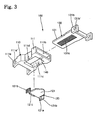
- FIG. 3 is an exploded perspective view of a first fastening part according to the present invention
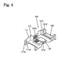
- FIG. 4 is an assembled perspective view of the first fastening part
- FIG. 5 is a view showing a fastened state of the first fastening part
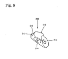
- FIG. 6 is a bottom perspective view of a second fastening part according to the present invention
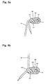
- FIG. 7 is a side view of the second fastening part.
- a lace fastening device for a footwear worn on a user in such a manner that a lace (L) is cross-fastened to connection links 14 oppositely formed on an instep portion of the footwear at regular intervals, which includes: a first fastening part 100 fastened between the connection links 14 to which the lace (L) is connected and having a fastening member 130 fastened to the inside of a receiving member 110 while rotating and restoring a control member 120, the first fastening part 100 releasing the fastened state of the fastening member 130 while rotating the control member 120 to separate it from a magnetic body 140; and a second fastening part 200 to which an end portion of the lace (L) passing the final connection link 14 of the footwear 10 is fit to and stackingly connected to the inside of a fixing member 210, so that the second fastening part 200 can keep a tightly fastened state of the lace while the upper end portion of the stackingly connected lace (L) pressurizes the lower end portion of
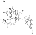
- the first fastening part 100 includes: the receiving member 110 having a body 111 inwardly dented at both side surfaces of the center thereof, the body 111 having a support piece 111a, which protrudes from a side thereof and has a through-hole 111a' to connect the lace (L) thereto, a receiving space 111b formed on the other side of the body 111 to fasten the fastening member 130, a mounting space 111c opened at the bottom of the body 111 to mount the control member thereon, and rotation holes 111d formed on both sides of the mounting space 111c; the control member 120 made of a metal material, the control member 120 having a control board 121 mounted in the mounting space 111c, the control board 121 having rotary shafts 121a formed at both sides thereof and inserted into the rotation holes 111d, control levers 121b formed on both ends of the rotary shafts 121a to rotate the control board 121, and a control protrusion 121c protruding from the rear portion of the control
- the second fastening part 200 includes: a fixing member 210 having a hollow formed therein and a fixing hole 211 to be fixed on the top of the instep of the footwear 10; a guide space 212 formed on a side of the fixing member 210 and having a movement preventing jaw 213 for preventing movement of the lace (L) fit to a side of the fixing member 210; and a guide rod 214 disposed on the lower end portion of the guide space 212 to guide the lace (L) to the guide space 212 while wrapping the lace (L).
- the lace fastening device further includes a third fastening part 300.
- the third fastening part 300 includes: a receiving member 310 having a body 311, which has a curved inner surface to be in close contact with the instep portion of the footwear 10 and has a coupling space 311a formed by an opened inside thereof, a fixing frame 312 fixed on the upper portion of the body 311 via a fixing screw 312a and having a spring 313 therein, a pressurizing piece 314 fit into the fixing frame 312 and having a semicircular section, a press piece 315 joined to an end of the pressurizing piece 314 through the body 311 for pressing the pressurizing piece 314, a release piece 316 rotatably mounted between the pressurizing piece 314 and the fixing frame 312, a plate spring 317 coupled to an end portion of the release piece 316 and operating elastically, and at least one connection link 318 formed at a side of the body to be connected with the lace (L); and a fastening
- the lace (L) is cross-connected at least once between the connection links 14 oppositely arranged at both sides of the footwear 10, and ends of the lace (L) direct the top of the footwear 10.
- the direction of the lace (L), the through-holes 111a' of the receiving member 110 and the through-holes 131b' of the fastening member 130 are located on the same line, and then, the lace (L) is connected to the through-holes 111a' and 131b' in a straight line.
- the receiving member 110 and the fastening member 130 of the first fastening part 100 keep a separated state.
- the front end of the lace (L) is inserted to the guide space 212, and more concretely, above the movement preventing jaw 213, and then, the inserted lace (L) is pushed to the lower end portion of the guide space 212 to be drawn outwardly from the fixing member 210.
- the front end of the drawn lace (L) is turned on the guide rod 214, and then, fit into the guide space 212 below the movement preventing jaw 213 in such a way as to be closely positioned beneath the lace (L) fit into the guide space 212.
- the lace (L) in a state where the lace (L) is inserted into the second fastening part 200, when the front end of the lace (L) located at the lower portion is pulled to the center of the footwear 10, the lace (L) is moved through the guide space 212.
- the front end of the lace (L) is pulled down, since the upper end portion of the lace (L) downwardly pressurizes the lower end portion of the lace (L), the lace (L) can keep a tightly fastened state without being loosened from the second fastening part 200.
- a user grasps the receiving member 110 and the fastening member 130, and then, inserts the fastening member 130 into the receiving space 111b.
- the fastening member 130 When the fastening member 130 is fastened to the receiving space 111b while passing the control protrusion 121c of the control member 120 made of the metal material, the control protrusion 121c of the control member 120 is rotated on the rotary shafts 121a by the fastening slots 131a of the fastening member 130, and at the same time, restored by a magnetic force of the magnetic body 140.
- the fastening member 130 is fastened to the receiving space 111b while repeating the above steps.
- control member 120 may have the control board 121 entirely made of the metal material or partially made of the metal material, namely, only a portion closely contacting with the magnetic body 140 is made of the metal material.
- the fastening member 130 is outwardly separated from the receiving member 110. After the separation of the fastening member 130, when the rotation of the control levers 121b is removed, the control member 120 is restored to the original state by the magnetic force of the magnetic body 140.
- the pressurizing force pressurizing the lower end portion of the lace (L) is removed, so that the lace (L) can be relaxed since the lower end portion of the lace (L) can be freely moved.
- the user grasps the receiving member 310 and the fastening member 320 with a hand, and then, inserts the fastening member 320 to the coupling space 311a of the receiving member 310.
- the retaining protrusion 321 of the fastening member 320 is in contact with the release piece 316 and fastened to the receiving member 310 while moving forward, and the release piece 316 supports the retaining protrusion 321 inclinedly protruding in one direction while contacting with the retaining protrusion 321 by elasticity of the plate spring 317, so that the fastened state between the receiving member 310 and the fastening member 320 can be kept without release.
- the pressurizing piece 314 having the semicircular section pressurizes a portion of the release piece 316, so that the release piece 316 is rotated toward the upper portion of the body 311 by the pressurizing piece 314 and separated from the retaining protrusion 321, whereby the fastened state can be released.
- the user rotates the receiving member 310 and the fastening member 320 toward both sides of the footwear 10 to laterally relax the footwear 10, so that the user can rapidly and easily take off the footwear.
- the lace fastening device according to the present invention can be applied to small footwears, which children wear, and to footwears having long ankle portions, such as mountain-climbing boots, military shoes, work shoes, and so on, and fasten the lace to the shoe while selectively controlling tightening and release.
- the lace fastening device is easy to mount and detach and simple in structure since a control member rotated while a fastening member is fastened to the inside of a receiving member is restored by a magnetic body, thereby reducing the manufacturing cost.
- the lace fastening device can rapidly fasten the lace to the shoe and keep a stable fastened state since the upper end portion of the lace fastened to the second fastening part pressurizes the lower end portion of the lace, thereby improving productivity.
Landscapes
- Footwear And Its Accessory, Manufacturing Method And Apparatuses (AREA)
- Basic Packing Technique (AREA)
Claims (4)
- Schnürsenkelbefestigungsvorrichtung für ein Schuhwerk, das von einem Nutzer derart getragen wird, dass ein Schnürsenkel (L) sich kreuzend mit Verbindungselementen (14) verbunden ist, die an einem Ristabschnitt des Schuhwerks in gleichmäßigen Abständen gegenüberliegend ausgebildet sind, umfassend
ein erstes Befestigungsteil (100), das zwischen den Verbindungselementen (14) befestigt ist, mit denen der Schnürsenkel (L) verbunden ist, und ein Befestigungselement (130) aufweist, das an der Innenseite eines Aufnahmeele-ments (110) befestigt ist, während ein Steuerelement (120) gedreht und zu-rückgestellt wird, wobei das erste Befestigungsteil (100) den befestigten Zu-stand des Befestigungselements (130) freigibt, während das Steuerelement (120) gedreht wird, um dieses von einem magnetischen Körper (140) zu tren-nen, und
ein zweites Befestigungsteil (200), an dem ein Endabschnitt des Schnürsen-kels (L), der durch das letzte Verbindungselement (14) des Schuhwerks (10) hindurchgeführt ist, ins Innere eines Fixierelements (210) eingeführt ist und mit diesem in einer aufeinanderliegenden Weise verbunden ist, so dass das zweite Befestigungsteil (200) einen fest verbundenen Zustand des Schnür-senkels aufrechterhalten kann, während der obere Endabschnitt des in einer aufeinanderliegenden Weise verbundenen Schnürsenkels (L) den unteren Endabschnitt des Schnürsenkels (L) mit Druck beaufschlagt. - Schnürsenkelbefestigungsvorrichtung gemäß Anspruch 1, wobei das erste Befestigungsteil (100) folgendes umfasst: das Aufnahmeelement (110), das einen Körper (111) aufweist, der an beiden Seitenflächen mittig eine nach in-nen gerichtete Eindellung aufweist, wobei der Körper (111) ein Stützteil (111a) aufweist, das von einer Seite desselben vorsteht und ein Durchgangsloch (111a') aufweist, um den Schnürsenkel (L) damit zu verbinden, einen Aufnahmefreiraum (111b), der an der anderen Seite des Körpers ausgebildet ist, um das Befestigungselement (130) festzusetzen, einen Befestigungsfreiraum (111c), der an dem Boden des Körpers (111) offen ist, um in diesem das Steuerelement zu befestigen, und Drehlöcher (111d), die an beiden Seiten des Befestigungsfreiraums (111c) ausgebildet sind; das Steuerelement (120), das aus einem Metallwerkstoff hergestellt ist, wobei das Steuerelement (120) eine Steuerplatte (121) aufweist, die in dem Befestigungsfreiraum (111c) montiert ist, wobei die Steuerplatte (121) Drehwellen (121a) aufweist, die an ihren beiden Seiten ausgebildet und in die Drehlöcher (111d) eingeführt sind, Steuerhebel (121b) aufweist, die an beiden Enden der Drehwellen (121a) ausgebildet sind, um die Steuerplatte (121) zu drehen, und einen Steuervorsprung (121c), der von dem hinteren Abschnitt der Steuerplatte (121) vorsteht, u m das Befestigungselement (130) lösbar zu befestigen; das Befestigungselement (130), das in dem Aufnahmefreiraum (111b) befestigt ist und eine Befestigungsplatte (131 aufweist, die eine Mehrzahl von Befestigungsschlitzen (131a aufweist, um den befestigten Zustand zwischen dem Steuerelement (120) und dem Befestigungselement (130) durch Verstellen des Steuervorsprungs (121c) zu lösen, Stützteile (131b) aufweist, die von beiden Seiten des hinteren Abschnitts der Befestigungsplatte (131) vorstehen und jeweils Durch-gangslöcher (131b') zum Befestigen des Schnürsenkels (L) an diesen aufweisen; und den magnetischen Körper (140) aufweist, der an der oberen Fläche des unteren Endkörpers (111) des Aufnahmefreiraums (111b) befestigt ist, um das Steuerelement (120), das wiederholt eine Drehung ausführt, zurückzustellen, während das Befestigungselement (130) an dem Steuerelement (120) befestigt wird.
- Schnürsenkelbefestigungsvorrichtung gemäß Anspruch 1, wobei das zweite Befestigungsteil (200) folgendes umfasst: ein Fixierelement (210), das einen Hohlraum und ein Befestigungsloch (211) aufweist, und das an dem oberen Abschnitt der Rist des Schuhwerks (10) befestigt wird; einen Führungsfrei-raum (212), der an einer Seite des Befestigungselements (210) ausgebildet ist und eine Bewegungsverhinderungsklaue (213) zur Verhinderung einer Bewegung des Schnürsenkels (L) aufweist, der an einer Seite des Befestigungselements (210) angebracht ist; und eine Führungsstange (214), die an dem unteren Endabschnitt des Führungsfreiraums (212) angeordnet ist, um den Schnürsenkel (L) zu dem Führungsfreiraum (212) zu führen, wahrend dieser den Schnürsenkel (L) umgibt.
- Schnürsenkelbefestigungsvorrichtung gemäß Anspruch 1 ferner umfassend ein drittes Befestigungsteil (300), das folgendes aufweist:ein Aufnahmeelement (310), das einen Körper (311) aufweist, der eine kur-venförmig verlaufende Innenfläche besitzt, die mit dem Ristabschnitt des Schuhwerks (10) in engen Kontakt stehen soll und einen Verbindungsfreiraum (311a) besitzt, der durch eine offene Innenseite desselben gebildet ist,einen Befestigungsrahmen (312), der an dem oberen Abschnitt des Körpers (311) mittels einer Befestigungsschraube (312a) befestigt ist und in diesem eine Feder (313) besitzt,ein Druckelement (314), das in dem Befestigungsrahmen (312) eingesetzt ist und einen halbkreisförmigen Querschnitt besitzt,ein Anpressteil (315), das mit einem Ende des Druckelements (314) durch den Körper (311) zum Anpressen des Druckelements (314) verbunden ist,ein Löseelement (316), das zwischen dem Druckelement (314) und dem Be-festigungsrahmen (312) drehbar angebracht ist,eine Blattfeder (317), die mit einem Endabschnitt des Löseelements (316) verbunden ist und elastisch wirkt,und wenigstens ein Verbindungselement (318), das an einer Seite des Kör-pers ausgebildet ist, um mit dem Schnürsenkel (L) verbunden zu werden,und ein Befestigungselement (320), das in den Verbindungsfreiraum (311a) eingeführt ist und eine Mehrzahl von Festsetzvorsprüngen (321) aufweist, die zur Verbindung mit dem Löseelement (316) in einer Richtung vorstehen,und wenigstens ein Verbindungselement (322), das an einer Seite desselben ausgebildet ist, mit der der Schnürsenkel (L) verbunden ist.
Applications Claiming Priority (3)
| Application Number | Priority Date | Filing Date | Title |
|---|---|---|---|
| KR20060038323 | 2006-04-27 | ||
| KR1020070035665A KR100833682B1 (ko) | 2006-04-27 | 2007-04-11 | 신발끈의 결속장치 |
| PCT/KR2007/002016 WO2007126241A1 (en) | 2006-04-27 | 2007-04-25 | Device for tying shoelaces |
Publications (3)
| Publication Number | Publication Date |
|---|---|
| EP2010016A1 EP2010016A1 (de) | 2009-01-07 |
| EP2010016A4 EP2010016A4 (de) | 2010-06-02 |
| EP2010016B1 true EP2010016B1 (de) | 2011-10-26 |
Family
ID=38655723
Family Applications (1)
| Application Number | Title | Priority Date | Filing Date |
|---|---|---|---|
| EP07746177A Not-in-force EP2010016B1 (de) | 2006-04-27 | 2007-04-25 | Vorrichtung zum binden von schuhbändern |
Country Status (10)
| Country | Link |
|---|---|
| US (1) | US20090172929A1 (de) |
| EP (1) | EP2010016B1 (de) |
| JP (1) | JP2009535087A (de) |
| KR (1) | KR100833682B1 (de) |
| CN (1) | CN101495006B (de) |
| AT (1) | ATE530082T1 (de) |
| BR (1) | BRPI0710391A2 (de) |
| MX (1) | MX2008013729A (de) |
| RU (1) | RU2391884C1 (de) |
| WO (1) | WO2007126241A1 (de) |
Families Citing this family (24)
| Publication number | Priority date | Publication date | Assignee | Title |
|---|---|---|---|---|
| US7866008B2 (en) * | 2006-01-19 | 2011-01-11 | Fotofeet, Inc. | Adjustable fastener for foot apparel |
| EP2076224B1 (de) | 2006-09-12 | 2016-08-24 | Boa Technology, Inc. | Verschlusssystem für gurte, schutzkleidung und ähnliche artikel |
| CN101820789A (zh) * | 2007-10-12 | 2010-09-01 | 黄钟午 | 鞋带捆绑工具 |
| KR100965674B1 (ko) * | 2008-02-22 | 2010-06-24 | 황종오 | 신발끈의 결속장치 |
| KR200467145Y1 (ko) | 2010-06-15 | 2013-05-29 | (주)앤제화 | 신발끈 조임장치를 갖는 신발 |
| KR20130103705A (ko) * | 2010-07-01 | 2013-09-24 | 보아 테크놀러지, 인크. | 끈 가이드 |
| US9113674B2 (en) * | 2011-12-15 | 2015-08-25 | Nike, Inc. | Footwear having an upper with forefoot tensile strand elements |
| KR20130068228A (ko) * | 2011-12-15 | 2013-06-26 | 김명규 | 신발 장신구 |
| US9185948B2 (en) | 2013-01-28 | 2015-11-17 | Jezekiel Ben-Arie | Buckle-lace: lace fastening device |
| USD769608S1 (en) | 2014-12-12 | 2016-10-25 | Zubits, Llc | Footwear closure |
| CN104665105A (zh) * | 2015-03-23 | 2015-06-03 | 杨星伟 | 一种固定和收纳鞋带的锁扣 |
| US9808050B2 (en) | 2015-11-08 | 2017-11-07 | Jezekiel Ben-Arie | Lace ratchet fastening device |
| US10390590B2 (en) | 2015-11-08 | 2019-08-27 | Jezekiel Ben-Arie | Lace ratcheting device II |
| US10786045B2 (en) | 2016-07-12 | 2020-09-29 | Jezekiel Ben-Arie | Lace ratcheting device—metal jacket |
| US10602807B2 (en) | 2016-07-12 | 2020-03-31 | Jezekiel Ben-Arie | Belt ratcheting device |
| US10582741B2 (en) | 2016-10-25 | 2020-03-10 | Under Armour, Inc. | Article of footwear with dynamic tensioning system |
| CN114343291A (zh) | 2016-11-03 | 2022-04-15 | 耐克创新有限合伙公司 | 快拉式鞋闭合装置 |
| US11241067B2 (en) | 2020-02-17 | 2022-02-08 | Jezekiel Ben-Arie | Hidden blade belt ratcheting device IV |
| US11234489B2 (en) | 2020-02-17 | 2022-02-01 | Jezekiel Ben-Arie | Spring lace ratcheting device |
| KR102401470B1 (ko) | 2020-07-23 | 2022-05-23 | 장정운 | 슈즈용 악세서리 |
| US11517077B2 (en) | 2020-12-25 | 2022-12-06 | Jezekiel Ben-Arie | Belt ratcheting device with hidden blade II |
| US11412818B1 (en) | 2021-01-26 | 2022-08-16 | Lawrence Skolnik | Retainer assembly for a knot |
| US20240237784A1 (en) * | 2023-01-13 | 2024-07-18 | Kipp Greene | Shoe Lace Buckle and System |
| TWI893927B (zh) * | 2024-08-05 | 2025-08-11 | 台灣扣具工業股份有限公司 | 繩帶扣及物件繩帶調整系統 |
Family Cites Families (20)
| Publication number | Priority date | Publication date | Assignee | Title |
|---|---|---|---|---|
| US2673381A (en) * | 1951-12-13 | 1954-03-30 | Fred E Dueker | Quick lace shoelace tightener |
| US4210983A (en) * | 1979-01-05 | 1980-07-08 | Green Robert L | Eyelet clamp for shoes |
| JPH02130209U (de) * | 1989-04-03 | 1990-10-26 | ||
| KR950009223Y1 (ko) * | 1992-07-03 | 1995-10-23 | 권영준 | 운동화의 끈 결착장치 |
| US5239732A (en) * | 1992-07-27 | 1993-08-31 | Zack Steven | Adjustable non-tying resilient securing apparatus for shoes |
| ITTV940037U1 (it) | 1994-07-13 | 1996-01-13 | Nordica Spa | Struttura di leva, particolarmente per calzature sportive |
| US5778498A (en) * | 1996-08-16 | 1998-07-14 | Laks; David A. | Releasable fastener for foot apparel |
| KR19990033746U (ko) * | 1999-05-14 | 1999-08-16 | 문진복 | 버클이부착되는조임끈을가지는신발 |
| TW411263B (en) | 1999-11-30 | 2000-11-11 | Taiwan Ind Fastener Corp | Braid buckle |
| GB0004821D0 (en) * | 2000-02-29 | 2000-04-19 | Clark Ltd C & J | Fastener for footwear |
| RU2177238C1 (ru) * | 2000-10-12 | 2001-12-27 | Попов Валерий Николаевич | Фиксатор шнурков для обуви |
| US6571432B1 (en) * | 2000-11-09 | 2003-06-03 | Salomon S.A. | Hidden closure |
| US6671980B1 (en) * | 2002-07-16 | 2004-01-06 | Kun-Chung Liu | Easy-to-wear footwear |
| JP2004135723A (ja) * | 2002-10-16 | 2004-05-13 | Takaharu Nonoda | 衣服用ベルト具 |
| JP3746043B2 (ja) * | 2003-02-07 | 2006-02-15 | 株式会社シマノ | ブーツライナー |
| US6662415B1 (en) * | 2003-03-10 | 2003-12-16 | Wen-Chi Lin | Fastener for lace |
| JP2005279015A (ja) * | 2004-03-30 | 2005-10-13 | Morito Co Ltd | 靴ひもの取付補助具 |
| KR200405410Y1 (ko) * | 2005-10-12 | 2006-01-11 | 백남일 | 버클 |
| KR200409510Y1 (ko) | 2005-11-10 | 2006-02-24 | 황종오 | 신발끈 결속장치 |
| KR200418045Y1 (ko) | 2006-03-16 | 2006-06-07 | 조종수 | 신발끈 조임수단이 구비된 신발 |
-
2007
- 2007-04-11 KR KR1020070035665A patent/KR100833682B1/ko not_active Expired - Fee Related
- 2007-04-25 RU RU2008141140/12A patent/RU2391884C1/ru not_active IP Right Cessation
- 2007-04-25 MX MX2008013729A patent/MX2008013729A/es active IP Right Grant
- 2007-04-25 AT AT07746177T patent/ATE530082T1/de not_active IP Right Cessation
- 2007-04-25 EP EP07746177A patent/EP2010016B1/de not_active Not-in-force
- 2007-04-25 CN CN200780014772.9A patent/CN101495006B/zh not_active Expired - Fee Related
- 2007-04-25 JP JP2009507594A patent/JP2009535087A/ja active Pending
- 2007-04-25 WO PCT/KR2007/002016 patent/WO2007126241A1/en not_active Ceased
- 2007-04-25 BR BRPI0710391-3A patent/BRPI0710391A2/pt not_active IP Right Cessation
- 2007-04-25 US US12/296,911 patent/US20090172929A1/en not_active Abandoned
Also Published As
| Publication number | Publication date |
|---|---|
| EP2010016A1 (de) | 2009-01-07 |
| MX2008013729A (es) | 2009-04-16 |
| BRPI0710391A2 (pt) | 2011-08-09 |
| CN101495006A (zh) | 2009-07-29 |
| EP2010016A4 (de) | 2010-06-02 |
| WO2007126241A1 (en) | 2007-11-08 |
| KR20070105849A (ko) | 2007-10-31 |
| RU2391884C1 (ru) | 2010-06-20 |
| US20090172929A1 (en) | 2009-07-09 |
| CN101495006B (zh) | 2011-02-16 |
| JP2009535087A (ja) | 2009-10-01 |
| ATE530082T1 (de) | 2011-11-15 |
| KR100833682B1 (ko) | 2008-05-29 |
Similar Documents
| Publication | Publication Date | Title |
|---|---|---|
| EP2010016B1 (de) | Vorrichtung zum binden von schuhbändern | |
| US8006410B2 (en) | Shoe, particularly sport or leisure shoe | |
| US4766682A (en) | Removable lace cover strap | |
| EP2399474B1 (de) | Schuh | |
| US20070084019A1 (en) | Ornamental rivet apparatus especially for clothing or shoes | |
| JP2016530028A (ja) | ワイヤの締付装置及びその装着方法 | |
| JP2013510685A (ja) | 早履き靴 | |
| US6158096A (en) | Shoe tongue positioner | |
| US20030221334A1 (en) | Link shoelace replacement | |
| US20110107619A1 (en) | Removable Eyelet Outer Rings for Footwear | |
| CN102631047A (zh) | 一种鞋拖鞋 | |
| USD605382S1 (en) | Footwear | |
| KR200425447Y1 (ko) | 신발용 악세사리 | |
| KR200273526Y1 (ko) | 신발끈 결속장치 | |
| KR101649149B1 (ko) | 신고 벗기 용이한 유아용 신발 | |
| KR200409510Y1 (ko) | 신발끈 결속장치 | |
| KR200267874Y1 (ko) | 신발용 끈 고정구 | |
| CN221511100U (zh) | 一种具有模块化装饰结构的运动鞋 | |
| CN215873660U (zh) | 一种鞋带收紧装置 | |
| KR200271353Y1 (ko) | 기능성 샌들 | |
| CN201504642U (zh) | 一种鞋带松紧装置 | |
| KR200278141Y1 (ko) | 뒤축이 탈, 부착되는 구두 | |
| JP3234117U (ja) | 靴紐結束具 | |
| JP3107586U (ja) | 履き物 | |
| JP3060154U (ja) | セパレートサンダル |
Legal Events
| Date | Code | Title | Description |
|---|---|---|---|
| PUAI | Public reference made under article 153(3) epc to a published international application that has entered the european phase |
Free format text: ORIGINAL CODE: 0009012 |
|
| 17P | Request for examination filed |
Effective date: 20081007 |
|
| AK | Designated contracting states |
Kind code of ref document: A1 Designated state(s): AT BE BG CH CY CZ DE DK EE ES FI FR GB GR HU IE IS IT LI LT LU LV MC MT NL PL PT RO SE SI SK TR |
|
| AX | Request for extension of the european patent |
Extension state: AL BA HR MK RS |
|
| A4 | Supplementary search report drawn up and despatched |
Effective date: 20100503 |
|
| RIC1 | Information provided on ipc code assigned before grant |
Ipc: A43C 11/14 20060101AFI20080206BHEP Ipc: A43C 7/00 20060101ALI20100426BHEP |
|
| GRAP | Despatch of communication of intention to grant a patent |
Free format text: ORIGINAL CODE: EPIDOSNIGR1 |
|
| RIC1 | Information provided on ipc code assigned before grant |
Ipc: A43C 11/14 20060101AFI20110118BHEP Ipc: A43C 7/00 20060101ALI20110118BHEP |
|
| DAX | Request for extension of the european patent (deleted) | ||
| GRAS | Grant fee paid |
Free format text: ORIGINAL CODE: EPIDOSNIGR3 |
|
| GRAA | (expected) grant |
Free format text: ORIGINAL CODE: 0009210 |
|
| AK | Designated contracting states |
Kind code of ref document: B1 Designated state(s): AT BE BG CH CY CZ DE DK EE ES FI FR GB GR HU IE IS IT LI LT LU LV MC MT NL PL PT RO SE SI SK TR |
|
| REG | Reference to a national code |
Ref country code: GB Ref legal event code: FG4D |
|
| REG | Reference to a national code |
Ref country code: CH Ref legal event code: EP |
|
| REG | Reference to a national code |
Ref country code: IE Ref legal event code: FG4D |
|
| REG | Reference to a national code |
Ref country code: DE Ref legal event code: R096 Ref document number: 602007018244 Country of ref document: DE Effective date: 20111222 |
|
| REG | Reference to a national code |
Ref country code: NL Ref legal event code: VDEP Effective date: 20111026 |
|
| LTIE | Lt: invalidation of european patent or patent extension |
Effective date: 20111026 |
|
| REG | Reference to a national code |
Ref country code: AT Ref legal event code: MK05 Ref document number: 530082 Country of ref document: AT Kind code of ref document: T Effective date: 20111026 |
|
| PG25 | Lapsed in a contracting state [announced via postgrant information from national office to epo] |
Ref country code: LT Free format text: LAPSE BECAUSE OF FAILURE TO SUBMIT A TRANSLATION OF THE DESCRIPTION OR TO PAY THE FEE WITHIN THE PRESCRIBED TIME-LIMIT Effective date: 20111026 Ref country code: IS Free format text: LAPSE BECAUSE OF FAILURE TO SUBMIT A TRANSLATION OF THE DESCRIPTION OR TO PAY THE FEE WITHIN THE PRESCRIBED TIME-LIMIT Effective date: 20120226 Ref country code: BE Free format text: LAPSE BECAUSE OF FAILURE TO SUBMIT A TRANSLATION OF THE DESCRIPTION OR TO PAY THE FEE WITHIN THE PRESCRIBED TIME-LIMIT Effective date: 20111026 |
|
| PG25 | Lapsed in a contracting state [announced via postgrant information from national office to epo] |
Ref country code: NL Free format text: LAPSE BECAUSE OF FAILURE TO SUBMIT A TRANSLATION OF THE DESCRIPTION OR TO PAY THE FEE WITHIN THE PRESCRIBED TIME-LIMIT Effective date: 20111026 Ref country code: PL Free format text: LAPSE BECAUSE OF FAILURE TO SUBMIT A TRANSLATION OF THE DESCRIPTION OR TO PAY THE FEE WITHIN THE PRESCRIBED TIME-LIMIT Effective date: 20111026 Ref country code: PT Free format text: LAPSE BECAUSE OF FAILURE TO SUBMIT A TRANSLATION OF THE DESCRIPTION OR TO PAY THE FEE WITHIN THE PRESCRIBED TIME-LIMIT Effective date: 20120227 Ref country code: SE Free format text: LAPSE BECAUSE OF FAILURE TO SUBMIT A TRANSLATION OF THE DESCRIPTION OR TO PAY THE FEE WITHIN THE PRESCRIBED TIME-LIMIT Effective date: 20111026 Ref country code: SI Free format text: LAPSE BECAUSE OF FAILURE TO SUBMIT A TRANSLATION OF THE DESCRIPTION OR TO PAY THE FEE WITHIN THE PRESCRIBED TIME-LIMIT Effective date: 20111026 Ref country code: GR Free format text: LAPSE BECAUSE OF FAILURE TO SUBMIT A TRANSLATION OF THE DESCRIPTION OR TO PAY THE FEE WITHIN THE PRESCRIBED TIME-LIMIT Effective date: 20120127 Ref country code: LV Free format text: LAPSE BECAUSE OF FAILURE TO SUBMIT A TRANSLATION OF THE DESCRIPTION OR TO PAY THE FEE WITHIN THE PRESCRIBED TIME-LIMIT Effective date: 20111026 |
|
| PG25 | Lapsed in a contracting state [announced via postgrant information from national office to epo] |
Ref country code: CY Free format text: LAPSE BECAUSE OF FAILURE TO SUBMIT A TRANSLATION OF THE DESCRIPTION OR TO PAY THE FEE WITHIN THE PRESCRIBED TIME-LIMIT Effective date: 20111026 |
|
| PG25 | Lapsed in a contracting state [announced via postgrant information from national office to epo] |
Ref country code: BG Free format text: LAPSE BECAUSE OF FAILURE TO SUBMIT A TRANSLATION OF THE DESCRIPTION OR TO PAY THE FEE WITHIN THE PRESCRIBED TIME-LIMIT Effective date: 20120126 Ref country code: SK Free format text: LAPSE BECAUSE OF FAILURE TO SUBMIT A TRANSLATION OF THE DESCRIPTION OR TO PAY THE FEE WITHIN THE PRESCRIBED TIME-LIMIT Effective date: 20111026 Ref country code: EE Free format text: LAPSE BECAUSE OF FAILURE TO SUBMIT A TRANSLATION OF THE DESCRIPTION OR TO PAY THE FEE WITHIN THE PRESCRIBED TIME-LIMIT Effective date: 20111026 Ref country code: DK Free format text: LAPSE BECAUSE OF FAILURE TO SUBMIT A TRANSLATION OF THE DESCRIPTION OR TO PAY THE FEE WITHIN THE PRESCRIBED TIME-LIMIT Effective date: 20111026 Ref country code: CZ Free format text: LAPSE BECAUSE OF FAILURE TO SUBMIT A TRANSLATION OF THE DESCRIPTION OR TO PAY THE FEE WITHIN THE PRESCRIBED TIME-LIMIT Effective date: 20111026 |
|
| PG25 | Lapsed in a contracting state [announced via postgrant information from national office to epo] |
Ref country code: RO Free format text: LAPSE BECAUSE OF FAILURE TO SUBMIT A TRANSLATION OF THE DESCRIPTION OR TO PAY THE FEE WITHIN THE PRESCRIBED TIME-LIMIT Effective date: 20111026 |
|
| PGFP | Annual fee paid to national office [announced via postgrant information from national office to epo] |
Ref country code: FR Payment date: 20120615 Year of fee payment: 6 Ref country code: GB Payment date: 20120419 Year of fee payment: 6 |
|
| PLBE | No opposition filed within time limit |
Free format text: ORIGINAL CODE: 0009261 |
|
| STAA | Information on the status of an ep patent application or granted ep patent |
Free format text: STATUS: NO OPPOSITION FILED WITHIN TIME LIMIT |
|
| PGFP | Annual fee paid to national office [announced via postgrant information from national office to epo] |
Ref country code: IT Payment date: 20120426 Year of fee payment: 6 |
|
| 26N | No opposition filed |
Effective date: 20120727 |
|
| REG | Reference to a national code |
Ref country code: DE Ref legal event code: R097 Ref document number: 602007018244 Country of ref document: DE Effective date: 20120727 |
|
| PG25 | Lapsed in a contracting state [announced via postgrant information from national office to epo] |
Ref country code: MC Free format text: LAPSE BECAUSE OF NON-PAYMENT OF DUE FEES Effective date: 20120430 |
|
| REG | Reference to a national code |
Ref country code: CH Ref legal event code: PL |
|
| PGFP | Annual fee paid to national office [announced via postgrant information from national office to epo] |
Ref country code: DE Payment date: 20120702 Year of fee payment: 6 |
|
| REG | Reference to a national code |
Ref country code: IE Ref legal event code: MM4A |
|
| PG25 | Lapsed in a contracting state [announced via postgrant information from national office to epo] |
Ref country code: LI Free format text: LAPSE BECAUSE OF NON-PAYMENT OF DUE FEES Effective date: 20120430 Ref country code: CH Free format text: LAPSE BECAUSE OF NON-PAYMENT OF DUE FEES Effective date: 20120430 Ref country code: IE Free format text: LAPSE BECAUSE OF NON-PAYMENT OF DUE FEES Effective date: 20120425 Ref country code: AT Free format text: LAPSE BECAUSE OF FAILURE TO SUBMIT A TRANSLATION OF THE DESCRIPTION OR TO PAY THE FEE WITHIN THE PRESCRIBED TIME-LIMIT Effective date: 20111026 |
|
| PG25 | Lapsed in a contracting state [announced via postgrant information from national office to epo] |
Ref country code: ES Free format text: LAPSE BECAUSE OF FAILURE TO SUBMIT A TRANSLATION OF THE DESCRIPTION OR TO PAY THE FEE WITHIN THE PRESCRIBED TIME-LIMIT Effective date: 20120206 |
|
| PG25 | Lapsed in a contracting state [announced via postgrant information from national office to epo] |
Ref country code: FI Free format text: LAPSE BECAUSE OF FAILURE TO SUBMIT A TRANSLATION OF THE DESCRIPTION OR TO PAY THE FEE WITHIN THE PRESCRIBED TIME-LIMIT Effective date: 20111026 |
|
| PG25 | Lapsed in a contracting state [announced via postgrant information from national office to epo] |
Ref country code: MT Free format text: LAPSE BECAUSE OF FAILURE TO SUBMIT A TRANSLATION OF THE DESCRIPTION OR TO PAY THE FEE WITHIN THE PRESCRIBED TIME-LIMIT Effective date: 20111026 |
|
| GBPC | Gb: european patent ceased through non-payment of renewal fee |
Effective date: 20130425 |
|
| PG25 | Lapsed in a contracting state [announced via postgrant information from national office to epo] |
Ref country code: GB Free format text: LAPSE BECAUSE OF NON-PAYMENT OF DUE FEES Effective date: 20130425 Ref country code: DE Free format text: LAPSE BECAUSE OF NON-PAYMENT OF DUE FEES Effective date: 20131101 |
|
| REG | Reference to a national code |
Ref country code: FR Ref legal event code: ST Effective date: 20131231 |
|
| REG | Reference to a national code |
Ref country code: DE Ref legal event code: R119 Ref document number: 602007018244 Country of ref document: DE Effective date: 20131101 |
|
| PG25 | Lapsed in a contracting state [announced via postgrant information from national office to epo] |
Ref country code: FR Free format text: LAPSE BECAUSE OF NON-PAYMENT OF DUE FEES Effective date: 20130430 Ref country code: IT Free format text: LAPSE BECAUSE OF NON-PAYMENT OF DUE FEES Effective date: 20130425 |
|
| PG25 | Lapsed in a contracting state [announced via postgrant information from national office to epo] |
Ref country code: TR Free format text: LAPSE BECAUSE OF FAILURE TO SUBMIT A TRANSLATION OF THE DESCRIPTION OR TO PAY THE FEE WITHIN THE PRESCRIBED TIME-LIMIT Effective date: 20111026 |
|
| PG25 | Lapsed in a contracting state [announced via postgrant information from national office to epo] |
Ref country code: LU Free format text: LAPSE BECAUSE OF NON-PAYMENT OF DUE FEES Effective date: 20120425 |
|
| PG25 | Lapsed in a contracting state [announced via postgrant information from national office to epo] |
Ref country code: HU Free format text: LAPSE BECAUSE OF FAILURE TO SUBMIT A TRANSLATION OF THE DESCRIPTION OR TO PAY THE FEE WITHIN THE PRESCRIBED TIME-LIMIT Effective date: 20070425 |