EP2009818A2 - Messverfahren für die Empfangsqualität, Steuerprogramm für die Übertragungsleistung und Vorrichtungen davon - Google Patents
Messverfahren für die Empfangsqualität, Steuerprogramm für die Übertragungsleistung und Vorrichtungen davon Download PDFInfo
- Publication number
- EP2009818A2 EP2009818A2 EP20080157991 EP08157991A EP2009818A2 EP 2009818 A2 EP2009818 A2 EP 2009818A2 EP 20080157991 EP20080157991 EP 20080157991 EP 08157991 A EP08157991 A EP 08157991A EP 2009818 A2 EP2009818 A2 EP 2009818A2
- Authority
- EP
- European Patent Office
- Prior art keywords
- symbol
- interest
- time
- rscp
- sir
- Prior art date
- Legal status (The legal status is an assumption and is not a legal conclusion. Google has not performed a legal analysis and makes no representation as to the accuracy of the status listed.)
- Granted
Links
Images


Classifications
-
- H—ELECTRICITY
- H04—ELECTRIC COMMUNICATION TECHNIQUE
- H04W—WIRELESS COMMUNICATION NETWORKS
- H04W52/00—Power management, e.g. Transmission Power Control [TPC] or power classes
- H04W52/04—Transmission power control [TPC]
- H04W52/18—TPC being performed according to specific parameters
- H04W52/24—TPC being performed according to specific parameters using SIR [Signal to Interference Ratio] or other wireless path parameters
- H04W52/243—TPC being performed according to specific parameters using SIR [Signal to Interference Ratio] or other wireless path parameters taking into account interferences
-
- H—ELECTRICITY
- H04—ELECTRIC COMMUNICATION TECHNIQUE
- H04B—TRANSMISSION
- H04B17/00—Monitoring; Testing
- H04B17/20—Monitoring; Testing of receivers
- H04B17/26—Monitoring; Testing of receivers using historical data, averaging values or statistics
-
- H—ELECTRICITY
- H04—ELECTRIC COMMUNICATION TECHNIQUE
- H04B—TRANSMISSION
- H04B17/00—Monitoring; Testing
- H04B17/30—Monitoring; Testing of propagation channels
- H04B17/309—Measuring or estimating channel quality parameters
- H04B17/336—Signal-to-interference ratio [SIR] or carrier-to-interference ratio [CIR]
-
- H—ELECTRICITY
- H04—ELECTRIC COMMUNICATION TECHNIQUE
- H04B—TRANSMISSION
- H04B17/00—Monitoring; Testing
- H04B17/30—Monitoring; Testing of propagation channels
- H04B17/309—Measuring or estimating channel quality parameters
- H04B17/345—Interference values
-
- H—ELECTRICITY
- H04—ELECTRIC COMMUNICATION TECHNIQUE
- H04W—WIRELESS COMMUNICATION NETWORKS
- H04W52/00—Power management, e.g. Transmission Power Control [TPC] or power classes
- H04W52/04—Transmission power control [TPC]
- H04W52/18—TPC being performed according to specific parameters
- H04W52/22—TPC being performed according to specific parameters taking into account previous information or commands
- H04W52/225—Calculation of statistics, e.g. average or variance
-
- H—ELECTRICITY
- H04—ELECTRIC COMMUNICATION TECHNIQUE
- H04W—WIRELESS COMMUNICATION NETWORKS
- H04W52/00—Power management, e.g. Transmission Power Control [TPC] or power classes
- H04W52/04—Transmission power control [TPC]
- H04W52/18—TPC being performed according to specific parameters
- H04W52/24—TPC being performed according to specific parameters using SIR [Signal to Interference Ratio] or other wireless path parameters
- H04W52/241—TPC being performed according to specific parameters using SIR [Signal to Interference Ratio] or other wireless path parameters taking into account channel quality metrics, e.g. SIR, SNR, CIR or Eb/lo
Definitions
- the present invention relates to a reception quality measurement method, transmission power control method and devices thereof, and more particularly, a reception quality measurement method, transmission power control method and devices thereof for a mobile station that receives F-DCPH symbols and CPICH symbols from a base station.
- a W-CDMA (UMTS) mobile communication system is one kind of radio communication interface that is based upon IMT-2000 (International Mobile Telecommunications-2000), and by using a maximum transmission speed of 384 Kbps, makes access of multimedia such as sound, moving images, data and the like possible.
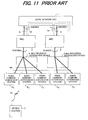
- this W-CDMA mobile communication system comprises: a core network 1; radio base station control devices (RNC: Radio Network Controllers) 2, 3; multiplexing/separation devices 4, 5; radio base stations (Node B) 6 1 to 6 5 ; and a mobile station (UE: User Equipment) 7.
- the core network 1 is a network for performing routing in the mobile communication system; for example, the core network can be an ATM exchange network, packet exchange network, router network, etc.
- the core network 1 is also connected to other public networks (PSTN), making it possible for a mobile station 7 to perform communication between itself and a fixed telephone or the like.
- the radio base station control devices (RNC) 2, 3 are located as host devices to the radio base stations 6 1 to 6 5 , and comprise functions for controlling these radio base stations 6 1 to 6 5 .
- the radio base station control devices 2, 3 also comprise a handover control function so that during handover, signals from one mobile station 7 are received by way of a plurality of subordinate radio base stations, and the data is selected from the signal having the best quality and transmitted to the core network 1.
- the multiplexing/separation devices 4, 5 are located between the RNC and radio base stations, and they perform control for separating signals that are received from the RNC 2, 3 and destined for each of the radio base stations, and together with outputting those signals to the radio base stations, multiplex signals from the radio base stations and transfer them to each RNC.
- the radio base stations 6 1 to 6 5 perform radio communication with the mobile station 7, and are such that RNC 2 manages the radio resources of the base stations 6 1 to 6 3 , and RNC 3 manages the radio resources of the base stations 6 4 , 6 5 .
- the mobile station 7 establishes a radio communication between itself and a radio base station 6i when it is within the radio communication area of the radio base station 6i, and performs communication between itself and another communication terminal by way of the core network 1.
- HSDPA High Speed Downlink Packet Access
- AMC Adaptive Modulation and Coding
- QPSK modulation scheme QPSK modulation scheme
- 16-value QAM method 16 QAM scheme
- the mobile stations when the mobile station detects an error in data received from the radio base station, the mobile stations sends a request (sends a NACK signal) to the radio base station to resend the data.
- the radio base station that receives this resend request resends the data, so the mobile station that has already received the data uses both this data and the resent data that it receives to perform error correction decoding.
- the main radio channels that are used in HSDPA are as follows:
- ⁇ Transmission Power Control In W-CDMA mobile communication, by identifying each of channels according to the spreading code that is allotted to each channel, a plurality of channels perform communication by sharing one frequency bandwidth.
- the reception signal receives interference from its own channel and other channels due do the delay wave in multipath fading or a radio signal from another cell, and that interference has an adverse effect on channel separation.
- the amount of interference that the reception signal receives changes over time due to instantaneous fluctuation in the reception power caused by the multipath fading, or change in the number of users communicating at the same time.
- the receiving side measures the signal to interference power ratio (SIR), and by comparing the measured SIR with a target SIR, transmission power control is performed to bring the SIR of the mobile station close to the target SIR.
- SIR signal to interference power ratio
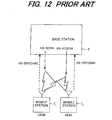
- FIG. 13 is drawing explaining transmission power control of a mobile station, and shows only one channel.
- the spreading modulation unit 6a of the base station 6 uses a spreading code that corresponds to a specified channel to spread and modulate transmission data, a power amplifier 6b amplifies the signal obtained by processing such as quadrature modulation and frequency conversion after the spreading modulation, and the amplified signal is sent to the mobile station 7 from the antenna.
- the inverse spreading unit 7a of the reception unit of the mobile station 7 performs inverse spreading on the reception signal, and the demodulation unit 7b demodulates the reception data.
- the SIR measurement unit 7c measures the power ratio between the reception signal and interference signal.
- the comparison unit 7d compares the measured SIR with a target SIR, and when the measured SIR is greater than the target SIR, creates a command to lower the transmission power by the TPC (Transmission Power Control) bit, and when the measured SIR is less than the target SIR, creates a command to raise the transmission power by the TPC bit.
- the target SIR is the SIR value that is necessary for obtaining 10 -3 (error occurrence rate of 1 time per 1000 times), and this value is input to the comparison unit 7d from the target SIR control unit 7e.
- the spreading modulation unit 7f spreads and modulates the transmission data and TPC bit.
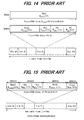
- FIG. 14 is a drawing showing the configuration of the individual physical channel DPCH (Dedicated Physical Channel) frame in the uplink that is normalized by the 3rd Generation Partnership Project (hereafter, referred to as 3GPP).
- DPCH Dedicated Physical Channel
- the dedicated physical channel DPCH comprises a DPDCH channel (Dedicated Physical Data Channel) by which only transmission data is transmitted, and DPCCH channel (Dedicated Physical Control Channel) by which control data such as a pilot and the TPC bit information that was explained in FIG. 13 are multiplexed and transmitted.
- the data transmitted by the DPDCH channel and DPCCH channel are spread by respective orthogonal code, after which the data is mapped and multiplexed on the real number axis and imaginary number axis.
- One frame in the uplink is 10 msec, and is configured with 15 slots (slot#0 to slot#14).
- the DPDCH channel is mapped on the I channel
- the DPCCH channel is mapped on the orthogonal Q channel.
- Each slot of the DPDCH channel comprises n bits, where n changes according to the symbol speed.
- Each slot of the DPCCH channel that transmits control data comprises 10 bits, where the symbol speed is fixed at 15 ksps, and transmits a pilot Pilot, transmission power control data TPC, transport format combination indicator TFCI, and feedback information FBI.
- BLER block error rate
- the mobile station performs outer-loop transmission power control to control the target SIR in order to obtain the desired quality (block error rate BLER).
- the target SIR control unit 7e inputs a target SIR that corresponds to the required BLER to the comparison unit 7d.
- the error-correction decoding unit 7g performs error detection/correction and decoding of the demodulated result from the demodulation unit 7b, and inputs the decoded result to the CRC detection unit 7h.
- the CRC detection unit 7h separates the decoded data into transport blocks TrBk, and then performs CRC error detection of each transport block TrBk and inputs the error detection results to the target SIR control unit 7e.
- the target SIR control unit 7e measures the actual BLER based on the error detection result, then compares the measured BLER wi th the requi red BLER, and when the reception state is poor and the measured BLER is greater than the required BLER, performs control to increase the target SIR, however when the reception state is good and the measured BLER is less than the required BLER, performs control to decrease the target SIR.
- This outer-loop transmission power control it is possible to control the transmission power so that the required BLER can be obtained.
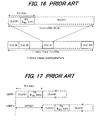
- FIG. 15 shows an example of the format of the dedicated physical channel DPCH in the downlink from a base station to a mobile station.
- One frame comprises 15 slots, slot #0 to slot #14, and each slot is configured so that a first data section Data1, TPC information, TFCI information, second data section Data2 and Pilot information are transmitted by time division multiplexing.
- the downlink dedicated channel DPCH is comprised of a DPDCH (Dedicated Physical Data Channel) that transmits data, and a DPCCH (Dedicated Physical Control Channel) that transmits control data (TPC information, TFCI information, Pilot).
- DPDCH Dedicated Physical Data Channel
- DPCCH Dedicated Physical Control Channel
- a F-DPCH Fractional Dedicated Physical Channel
- 3GPP release 6 3rd Generation Partnership Project Release 6
- the base station assigns one spreading code to F-DPCH, and spreads that F-DPCH by that spreading code, and as showing in FIG. 17 by making the transmission timing (offset) different for each user, performs transmission so that TPC symbols do no overlap between different users.
- the base station uses a F-DPCH instead of the dedicated channel DPCH to transmit only a TPC symbol to a user for which there is no data to transmit over the dedicated channel DPCH, and in so doing solves the problem of insufficient resources.
- FIG. 18 is a drawing explaining the transmission timing of a downlink F-DPCH that is transmitted from the base station, and a DPCCH (see FIG. 14 ) that is transmitted from the mobile station and includes a TPC bit.
- the F-DPCH is transmitted being delayed a specified offset Toff for each user from a reference timing T0 at which the downlink CPICH (Common Pilot Channel) or P-CCPCH (Primary Common Control Physical Channel) is transmitted.
- the mobile station receives the TPC bit that is included in the F-DPCH and measures the SIR, then performs transmission power control based on that SIR. After a time of 1024 chips from the transmission timing of the F-DPCH, the mobile station transmits an uplink DPCCH that includes a TPC bit, which is the transmission power control data, to the base station.
- the timing that this uplink DPCCH is transmitted to the base station is a time that set according to the 3GPP and is a fixed time.
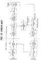
- FIG. 19 is a drawing showing the construction of a conventional mobile station, and shows the main construction of parts for receiving the TPC bit that is included in the F-DPCH, measuring the SIR, performing transmission power control based on that SIR, setting a TPC bit as transmission power control information, and sending an uplink DPCCH that includes that TPC bit to the base station.
- the radio signal that is sent from the base station is received by the antenna and input to the receiver 11.
- the receiver 11 After performing down conversion of the radio signal to a baseband signal, the receiver 11 performs processing such as quadrature modulation, AD conversion, inverse spreading and the like on the obtained baseband signal, and outputs a F-DPCH symbol signal, CPICH symbol signal and reception timing signal (frame synchronization signal, slot synchronization signal).
- a channel estimation filter 12 used for calculating the RSCP calculates the average value of the previous n symbols to the current symbol, for example the average of 10 symbols, of the CPICH symbol signal, then computes the channel estimation value from that average value and outputs it at the symbol cycle.
- One slot of the CPICH comprises 10 symbols, so these 10 symbols are equivalent to the portion of one slot.
- An RSCP measurement processing unit 13 performs channel compensation on the F-DPCH symbol signal (TPC symbol) based on the channel estimation value input from channel estimation filter 12, then measures the reception power of that TPC symbol and inputs the result to a SIR measurement processing unit 14 as the RSCP.
- a channel estimation filter 15 used for calculating the ISCP calculates the average value of the 10 symbols previous to the current symbol of the CPICH symbol signal, then computes the channel estimation value from that average value and outputs the result at the symbol cycle.
- An ISCP measurement processing unit 16 calculates the power of the interference signal using a CPICH symbol that was received at the same reception timing as the TPC symbol of the F-DPCH, a known CPICH symbol, and the channel estimation value input from the channel estimation filter 15, and inputs the result to the SIR measurement processing unit 14 as the ISCP.
- the SIR measurement processing unit 14 uses the input RSCP and ISCP to calculate and output the SIR according to the equation below.
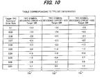
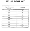
- FIG. 20 shows an example of a target TPC error rate/target SIR conversion table
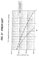
- FIG. 21 is a graph showing the characteristics of the TPC error rate versus the target SIR, where A is the characteristics in a normal environment.
- the TPC command generation unit 20 sets a TPC command (Up or Down) from the measured SIR result and the target SIR, and inputs that TPC command to a DPCCH processing unit (Pilot/TFCI/FBI/TPC scheduling unit) 21.
- a DPCCH processing unit Pilot/TFCI/FBI/TPC scheduling unit 21.
- a downlink reception timing monitoring unit 22 monitors the downlink timing based on the reception timing signal (frame synchronization signal, slot synchronization signal), and an uplink transmission timing management uni t 23 inputs a transmission timing signal to the DPCCH processing unit 21.
- the DPCCH processing unit 21 performs time division multiplexing of the uplink DPCCH Pilot, TFCI, FBI and TPC, and outputs a DPCCH symbol in synchronization with the transmission timing signal.
- a DPCCH encoding unit 24 encodes the input DPCCH symbol
- a modulation unit 25 performs modulation of the DPCHH and other uplink channels
- a transmitter 26 converts the modulated signal to a radio signal and transmits it toward the base station.
- FIG. 22 is a drawing showing a time chart image in symbol units of the calculation process of ISCP, RSCP and SIR in the F-DPCH.
- the channel estimation filter 12 for calculating the RSCP performs the channel estimation filtering process using the reception wave of slot #n-1 of the CPICH (step 101).
- the RSCP measurement processing unit 13 measures the reception power RSCP of that TPC symbol and inputs it to the SIR measurement processing unit 14 (step 102).
- the channel estimation filter 15 for calculating the ISCP also performs the channel estimation filtering process using the reception wave of slot #n-1 of the CPICH (step 103).
- the ISCP measurement processing unit 16 calculates the reception power ISCP of the interference signal using a CPICH symbol that is received at the same reception timing as the TPC symbol of the F-DPCH, a known CPICH symbol and the channel estimation value that was obtained in step 103, and inputs it to the SIR measurement unit 14 (step 104).
- the SIR measurement processing unit 14 uses the input RSCP and ISCP to calculate and output the SIR (step 105).
- the mobile station measures the SIR, then based on the size of the measured SIR and a target SIR, decides the TPC bit, and maps that TPC bit on the uplink DPCCH that is sent 1024 chips after receiving the F-DPCH, and transmits it to the base station.
- the mobile station performs channel estimation using the reception wave of slot #n-1 of the CPICH, and measures the SIR of the TPC symbol of the F-DPCH of slot #n.
- the channel estimation value that was measured using the reception wave of slot #n-1 of the CPICH indicates a value at the center time (past time) of that slot #n-1, and is not the channel estimation value at the reception time of the F-DPCH symbol of slot #n.
- the channel estimation result varies in a short period of time in a fading environment or multipath environment, there generates an environment where the past channel estimation value and current channel estimation value differ, and as a result a phenomenon occurs in which there is deterioration of the ISCP value in regard to the accuracy.
- the interference power is a physical quantity that is not affected by the fading environment or multipath environment of a mobile device, so in a fading environment or multipath environment, that precision of the ISCP deteriorates. Therefore, the SIR measurement precision of the F-DPCH deteriorates, and it becomes impossible to perform transmission power control with high enough precision to be able to obtain the target error rate as a target.
- FIG. 20 is one example of a table for converting the Target TPC Command Error Rate (target error rate) to the SIR of the F-DPCH
- FIG. 21 is a graph that quantitatively shows the SIR and TPC Command Error Rate when the F-DPCH is received in a normal environment and in a fading environment, where A is the characteristics in a normal environment, and B is the characteristics in a fading environment.
- the Target TPC Command Error Rate is 10 -2
- the target SIR in a normal environment is 0.7 dB
- the target SIR becomes 5 dB. Therefore, in a fading environment, the target SIR that should be set to 5 dB is set as 0.7 dB, and as a result, the base station is not able to perform proper power control of the F-DCPH, so a problem occurs in that the transmission to the mobile station is performed at a power greater than is necessary, radio communication resources are used to excess, and the due to this the throughput of the system drops.
- the F-DPCH may be transmitted at a power below the reception capability of the mobile station, and in such a case, a problem occurs in that the TPC Command Error Rate cannot be obtained as a target.
- a techn i que has been disclosed as pr i or art i n wh i ch recept i on quality is measured with good precision (see WO 2007/004292 ).
- reception quality that is calculated in the past is saved as a first reception quality, and the current reception quality is calculated as a second reception quality, the difference between the second reception quality and first reception quality is then calculated as a correction value, and the reception quality is corrected using this correction value.
- this prior art is not a method for accurately measuring the RSCP (Received Signal Code Power) and LSCP (Interference on Signal Code Power) in the F-DPCH channel, or calculating the SIR correctly.
- the prior art does not disclose a technique for accurately measuring the RSCP or ISCP in the F-DPCH channel.
- this prior art is not a method for performing transmission power control so that the desired error rate is obtained.
- RSCP Receive i ved Signal Code Power
- ISCP Interference on Signal Code Power
- An embod i ment of a first aspect of the invention is a reception quality measurement method for a mobile station that receives F-DCPH symbols and CPICH symbols from a base station, comprising: a step of averaging a plurality of CPICH symbols in a time sequence before a certain time of interest and estimating the channel, then using the obtained channel estimation value and CP I CH symbol at the time of interest to calculate the interference power ISCP; a step of averaging a plurality of CPICH symbols in a time sequence that include the CPICH symbol at the time of interest and estimating the channel, then using the obtained channel estimation value and the CP I CH symbol at that time of interest to calculate a reference ISCP; a step of correcting the ISCP at the next time of interest using the difference between the ISCP and the reference ISCP; and a step of using the ISCP that is found from the cor rect i on and the RSCP of the F-DCPH symbol to calculate the signal to interference power ratio SIR of the mobile
- the reception quality measurement method of the embodiment may further comprise: a step of averag i ng a plurality of CP I CH symbols in a time sequence before a certain time of interest and estimating the channel, then using the obtained channel estimation value and F-DCPH symbol at the time of interest to calculate the reception power RSCP of that symbol; a step of averaging a plurality of CPICH symbols in a time sequence that include the CP I CH symbol at the time of interest and estimating the channel, then using the obtained channel estimation value and the F-DCPH symbol at that time of interest to calculate a reference RSCP; and a step of correcting the RSCP at the next time of interest using the difference between the RSCP and the reference RSCP.
- the reception quality measurement method of the embodiment may even further comprise a step of generat i ng transm i ss i on power information based on the size of the calculated SIR and a target SIR, and sending that information to the base station.
- An embodiment of a second aspect of the invention is a transmission power control method for a mobile station that receives F-DCPH symbols and CPICH symbols from a base station.
- a first embod i ment of the transm i ss i on power control method comprises: a step of averaging a plurality of CPICH symbols in a time sequence before a certain time of interest and estimating the channel, then using the obtained channel estimation value and CP I CH symbol at the time of interest to calculate the interference power ISCP; a step of averaging a plurality of CPICH symbols in a time sequence that include the CPICH symbol at the time of interest and estimating the channel, then using the obtained channel estimation value and the CP I CH symbol at that time of interest to calculate a reference ISCP; a step of setting a target error rate/target SIR correlation table based on the difference between the ISCP and the reference ISCP; a step of using that table to find a target SIR that corresponds to a target error rate; a step of using the RSCP and ISCP at the next time of interest to calculate the SIR; and a step of generating transmission power information based on the size of the calculated SIR and the target SIR
- a second embodiment of the transmission power control method comprises: a step of averaging a plurality of CPICH symbols in a time sequence before a certain time of interest and estimating the channel, then using the obtained channel estimation value and F-DCPH symbol at the time of interest to calculate the reception power RSCP of that symbol; a step of averaging a plurality of CPICH symbols in a time sequence that include the CPICH symbol at the time of interest and estimating the channel, then using the obtained channel estimation value and the F-DCPH symbol at that time of interest to calculate a reference RSCP; a step of setting a target error rate/target SIR correlation table based on the difference between the RSCP and the reference RSCP; a step of us i ng that tab I e to find a target SIR that corresponds to a target error rate; a step of using the RSCP and ISCP at the next time of interest to calculate the SIR; and a step of generating transmission power information based on the size of the calculated SIR and said target S
- a th i rd embod i ment of the transm i ss i on power control method comprises: a step of averaging a plurality of CPICH symbols in a time sequence before a certain time of interest and estimating the channel, using the obtained channel estimation value to perform channel compensation of the F-DCPH symbol at the time of interest, then decoding the channel compensated F-DCPH symbol and outputting the decoded result; a step of averaging a plurality of CPICH symbols in a time sequence that include the CPICH symbol at the time of interest and estimating the channel, using the obtained channel estimation value to perform channel compensation of the F-DCPH symbol at the time of interest, then decoding the channel compensated F-DCPH symbol and outputting a reference decoded result; a step of setting a target error rate/target SIR correlation table based on the decoding error rate that is obtained by comparing the decoded result and the reference decoded result; a step of using that table to find a target SIR that corresponds to
- RSCP Receive i ved Signal Code Power
- I SCP Interference on Signal Code Power
- by using a suitable conversion table it may be possible to set a target SIR that corresponds to a target error rate even in a fading environment, and it may be possible to perform transmission power control so that that error rate is obtained.
- This ISCP (Interference on Signal Code Power) includes error since it uses the past channel estimation value.
- This reference ISCP does not include error since it uses the channel estimation value at the reception time of the TPC symbol S TPCn-1 .
- B - A ⁇ ISCP
- This ISCP includes error since a past channel estimation value is used.
- the method uses ⁇ ISCP to correct the ISCP according to the equation below (step 208).
- ISCP A ⁇ + ⁇ ISCP
- the error ⁇ ISCP at the reception time of the TPC symbol S TPCn-1 in the previous (n-1)th slot can be regarded as being nearly the same as the error at the reception time of the TPC symbol S TPCn in the current nth slot, so the ISCP is corrected by the equation above.
- the method performs channel estimation of the F-DPCH using the ten CPICH symbols S CPI4 that are immediately before the TPC symbol S TPCn in the nth slot that is transmitted from the base station (step 209), and uses that channel estimation value to perform channel compensation of the F-DPCH symbol signal (TPC symbol S TPCn ), after which the method calculates the RSCP (Received Signal Code Power) of that TPC symbol S TPCn (step 210). Finally, the method uses the ISCP that was corrected in step 208 and the RSCP that was obtained in step 210 to calculate the SIR at the reception time of the TPC symbol S TPCn according to the equation below (step 211).
- SIR RSCP / ISCP After that, the method uses this SIR to perform control to generate a transmission power control bit TPC.
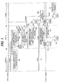
- FIG. 2 is a drawing showing the construction of a mobile station of a first embodiment of the invention.
- a radio signal that is transmitted from a base station is received by an antenna and input to a receiver 51.
- the receiver 51 After performing down conversion of the radio signal to a baseband signal, the receiver 51 performs processing such as quadrature modulation, AD conversion and inverse spreading of the obtained baseband signal, and outputs a F-DPCH symbol signal, a CPICH symbol signal, and a reception timing signal (frame synchronization signal, slot synchronization signal).
- processing such as quadrature modulation, AD conversion and inverse spreading of the obtained baseband signal
- the receiver 51 After performing down conversion of the radio signal to a baseband signal, the receiver 51 performs processing such as quadrature modulation, AD conversion and inverse spreading of the obtained baseband signal, and outputs a F-DPCH symbol signal, a CPICH symbol signal, and a reception timing signal (frame synchronization signal, slot synchronization signal).
- the receiver 51 receives the F
- a channel estimation filter 52 for calculating the RSCP always saves the ten most recent CPICH symbols that are immediately before the currently received symbol, and uses these CP I CH symbols to estimate the F-DPCH channel. Therefore, when the TPC symbol S TPCn-1 in the (n-1)th slot is received from the base station, the channel estimation filter 52 uses the ten CPICH symbols SCPI0 to estimate the channel (step 191 in FIG. 1 ), and a RSCP measurement unit 53 uses that channel estimation value to perform channel compensation on the TPC symbol STPCn-1, and then calculates and outputs the RSCP of that TPC symbol STPCn-1 (step 192).
- a target SIR control unit 71 make a reference to a target error rate/target SIR conversion table 73 and finds a target SIR that corresponds to the target error rate, and inputs that target SIR to the TPC command generation unit 58.
- the TPC command generation unit 58 decides a TPC command (Up or Down) based on the size of the SIR measurement result and target SIR, and inputs that TPC command to a DPCCH processing unit 74.
- a downlink reception timing monitoring unit 75 monitors the downlink timing based on the reception timing signal (frame synchronization signal, slot synchronization signal), and a uplink transmission timing management unit 76 inputs a transmission timing signal to the DPCCH processing unit 74.
- the DPCCH processing unit 74 performs time division multiplexing of the Pilot, TFCI, FBI and TPC of the uplink DPCCH, and in synchronization with the transmission timing signal, outputs a DPCCH symbol.
- a DPCCH encoding unit 77 encodes the input DPCCH symbol
- a modulation unit 78 modulates the DPCCH and other upl ink channels
- a transmitter 79 converts the modulated signal to a radio signal and transmits it toward the base station.
- a CPICH buffer 59 for calculating a reference ISCP saves the CPICH symbol that was received at the same time that the TPC symbol S TPCn-1 was received, and a channel estimation filter 60 for calculating a reference ISCP saves the ten most recent CPICH symbols, which are delayed a few symbols (7 symbols in the figure) from the ten CPICH symbols stored in the channel filter 54 for calculating the ISCP, in order in an internal buffer.
- the channel estimation filter 60 for calculating the reference ISCP uses the ten CP I CH symbols S CPI2 to estimate the channel (step 203). This channel estimation value is the channel estimation value at the time that the TPC symbol S TPCn-1 is received.
- This reference ISCP does not include error since it uses the channel estimation value at the reception timing of the TPC symbol S TPCn-1 .
- the channel estimation filter 54 for calculating the ISCP uses the ten CPICH symbols S CPI3 that are immediately before the reception time of the TPC symbol S TPCn in the nth slot that is sent from the base station to perform channel estimation (step 206), and the ISCP measurement unit 55 calculates the reception power ISCP of the interference signal using the CPICH symbol that is received at the same time that the TPC symbol S TPCn is received, an already known CP I CH symbol and the channel estimation value that is estimated in step 206 (step 207), and together with inputting the result to the ISCP correction unit 56b as A', saves that ISCP in the buffer 57 as A.
- This ISCP includes error since it uses a past channel estimation value.
- the ISCP correction unit 56b uses the difference ⁇ ISCP that is input from the ISCP error calculation unit 62 to correct the ISCP according to Equation (2) (step 208). Moreover, when the TPC symbol S TPCn in the nth slot is received from the base station, the channel estimation filter 52 for calculating the RSCP uses the immediately preceding ten CPICH symbols S CPU4 to perform channel estimation (step 209), and the RSCP measurement unit 53 uses that channel estimation value to perform channel compensation of the TPC symbol S TPCn , after which RSCP measurement unit 53 calculates and outputs the RSCP of that TPC symbol S TPCn (step 210).
- the SIR measurement unit 56a of the corrected SIR calculation unit 56 uses the RSCP and ISCP that are input from the RSCP measurement unit 53 and ISCP correction unit 56b to calculate the SIR according to Equation (3), and inputs that SIR to the TPC command generation unit 58 (step 211).
- the TPC generation unit 58 uses this SIR and the target SIR to perform control to generate a transmission power control bit TPC. After that, the SIR calculation process and TPC bit generation process are performed as described above. With this first embodiment, it is possible to accurately measure the ISCP and to calculate a correct SIR, and thus it is possible to generate a TPC bit so that a desired error rate is obtained.
- the first embodiment improves the measurement precision of the SIR by accurately measuring the ISCP, and generates a transmission power control bit TPC so that a desired error rate is obtained and sends that TPC to a base station.
- This second embodiment improves the measurement precision of the SIR by accurately measuring the RSCP, and generates a transmission power control bit TPC so that a desired error rate is obtained and sends that TPC to a base station.
- FIG. 3 is a drawing that explains the operation of the SIR measurement method of this second embodiment.
- This RSCP includes error since it uses a past channel estimation value.
- This reference RSCP does not include error since it uses the channel estimation value at the reception timing of the TPC symbol S TPCn-1 .
- B - A ⁇ RSCP
- This RSCP includes error since it uses a past channel estimation value.
- the method uses the difference ⁇ RSCP that is obtained in step 305 and corrects the RSCP according to the equation below (step 308).
- RSCP A ′ + ⁇ RSCP
- the error ⁇ RSCP at the time that the TPC symbol S TPCn-1 in the previous (n-1)th slot is received can be regarded as being nearly equivalent to the error at the time that the TPC symbol S TPCn in the current nth slot is received, so RSCP is corrected by the equation above.
- the method uses the ten CPICH symbols S PCI4 that are immediately before the reception time of the TPC symbol S TPCn in the nth slot that is transmitted from the base station to perform channel estimation (step 309), then uses that channel estimation value, the CPICH symbol at the reception time of the TPC symbol S TPCn , and an already known CP I CH symbol to calculate the ISCP of the interference signal (step 310).
- the method uses the RSCP that was corrected in step 308 and the ISCP that was found in step 310 to calculate the SIR at the reception timing of the TPC symbol S TPCn (step 311). After that, the method uses this SIR to perform control to generate a transmission power control bit TPC.
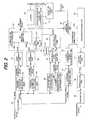
- FIG. 4 is a drawing showing the construction of a mobile station of this second embodiment, where the same reference numbers are given to parts that are identical to those in the first embodiment shown in FIG. 2 . This embodiment differs by the point given below.
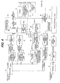
- FIG. 5 is a drawing showing the construction of a mobile station of a third embodiment of the invention, where the same reference numbers are given to parts that are identical to those in the first embodiment shown in FIG. 2 . This embodiment differs by the points described below.
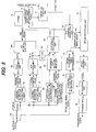
- FIG. 7 is a drawing showing the construction of a mobile station of a fourth embodiment of the invention, where the same reference numbers are given to parts that are identical to those of the second embodiment shown in FIG. 4 . This embodiment differs in points given below.
- FIG. 9 is a drawing showing the construction of a mobile station of a fifth embodiment of the invention, where the same reference numbers are given to parts that are identical to those of the second embodiment shown in FIG. 4 . This embodiment differs by the points described below.
Landscapes
- Engineering & Computer Science (AREA)
- Computer Networks & Wireless Communication (AREA)
- Signal Processing (AREA)
- Physics & Mathematics (AREA)
- Quality & Reliability (AREA)
- Electromagnetism (AREA)
- Probability & Statistics with Applications (AREA)
- Mobile Radio Communication Systems (AREA)
Priority Applications (1)
| Application Number | Priority Date | Filing Date | Title |
|---|---|---|---|
| EP10193530.2A EP2320583B1 (de) | 2007-06-25 | 2008-06-10 | Messverfahren für die Empfangsqualität, Steuerprogramm für die Übertragungsleistung und Vorrichtungen davon |
Applications Claiming Priority (1)
| Application Number | Priority Date | Filing Date | Title |
|---|---|---|---|
| JP2007165937A JP4888245B2 (ja) | 2007-06-25 | 2007-06-25 | 受信品質測定方法及び送信電力制御方法ならびにそれらの装置 |
Related Child Applications (2)
| Application Number | Title | Priority Date | Filing Date |
|---|---|---|---|
| EP10193530.2A Division-Into EP2320583B1 (de) | 2007-06-25 | 2008-06-10 | Messverfahren für die Empfangsqualität, Steuerprogramm für die Übertragungsleistung und Vorrichtungen davon |
| EP10193530.2A Division EP2320583B1 (de) | 2007-06-25 | 2008-06-10 | Messverfahren für die Empfangsqualität, Steuerprogramm für die Übertragungsleistung und Vorrichtungen davon |
Publications (3)
| Publication Number | Publication Date |
|---|---|
| EP2009818A2 true EP2009818A2 (de) | 2008-12-31 |
| EP2009818A3 EP2009818A3 (de) | 2010-06-02 |
| EP2009818B1 EP2009818B1 (de) | 2016-11-23 |
Family
ID=39730710
Family Applications (2)
| Application Number | Title | Priority Date | Filing Date |
|---|---|---|---|
| EP10193530.2A Ceased EP2320583B1 (de) | 2007-06-25 | 2008-06-10 | Messverfahren für die Empfangsqualität, Steuerprogramm für die Übertragungsleistung und Vorrichtungen davon |
| EP08157991.4A Ceased EP2009818B1 (de) | 2007-06-25 | 2008-06-10 | Messverfahren für die Empfangsqualität, Steuerprogramm für die Übertragungsleistung und Vorrichtungen davon |
Family Applications Before (1)
| Application Number | Title | Priority Date | Filing Date |
|---|---|---|---|
| EP10193530.2A Ceased EP2320583B1 (de) | 2007-06-25 | 2008-06-10 | Messverfahren für die Empfangsqualität, Steuerprogramm für die Übertragungsleistung und Vorrichtungen davon |
Country Status (3)
| Country | Link |
|---|---|
| US (1) | US7830818B2 (de) |
| EP (2) | EP2320583B1 (de) |
| JP (1) | JP4888245B2 (de) |
Cited By (2)
| Publication number | Priority date | Publication date | Assignee | Title |
|---|---|---|---|---|
| EP2367384A1 (de) * | 2010-03-05 | 2011-09-21 | Fujitsu Limited | Mobiles Endgerät und Leistungssteuerungsverfahren |
| KR20130122504A (ko) * | 2012-04-30 | 2013-11-07 | 삼성전자주식회사 | 무선 통신 시스템에서 송신 전력을 추정하기 위한 시스템 및 방법 |
Families Citing this family (13)
| Publication number | Priority date | Publication date | Assignee | Title |
|---|---|---|---|---|
| US9072120B2 (en) * | 2008-07-21 | 2015-06-30 | Go Net Systems Ltd. | Methods circuits and systems for providing cellular base station functionality at one or more nodes of a data network |
| GB0820535D0 (en) * | 2008-11-10 | 2008-12-17 | Icera Inc | Communication system and method |
| EP2410784B2 (de) * | 2009-03-20 | 2017-02-15 | Huawei Technologies Co., Ltd. | Verfahren zum empfangen und rückkoppeln von vorkodierten steueranzeigeinformationen und kommunikationsvorrichtung dafür |
| JP5199930B2 (ja) * | 2009-03-23 | 2013-05-15 | 株式会社エヌ・ティ・ティ・ドコモ | 受信装置 |
| GB0905357D0 (en) * | 2009-03-27 | 2009-05-13 | Icera Inc | Estimation of signal and interference power |
| WO2011111751A1 (ja) * | 2010-03-12 | 2011-09-15 | 京セラ株式会社 | 無線通信システム、高電力基地局、低電力基地局、及び、無線通信方法 |
| US8699548B2 (en) * | 2010-11-17 | 2014-04-15 | Qualcomm Incorporated | LO generation and distribution in a multi-band transceiver |
| WO2012092801A1 (zh) * | 2011-01-04 | 2012-07-12 | 中兴通讯股份有限公司 | 一种上行闭环发送分集的信息反馈方法和装置 |
| WO2011144112A2 (zh) | 2011-05-27 | 2011-11-24 | 华为技术有限公司 | 语音信号处理方法、装置和接入网系统 |
| GB2506937B (en) * | 2012-10-15 | 2015-06-10 | Toshiba Res Europ Ltd | A transceiver operating in a wireless communications network, a system and method for transmission in the network |
| CN103841630B (zh) * | 2012-11-26 | 2018-09-14 | 南京中兴软件有限责任公司 | 一种控制用户设备功率的方法及装置 |
| WO2014161158A1 (zh) * | 2013-04-02 | 2014-10-09 | 华为技术有限公司 | 信道配置方法、设备及系统 |
| CN103473322A (zh) * | 2013-09-13 | 2013-12-25 | 国家电网公司 | 基于时间序列模型的光伏发电功率超短期预测方法 |
Citations (1)
| Publication number | Priority date | Publication date | Assignee | Title |
|---|---|---|---|---|
| WO2007004292A1 (ja) | 2005-07-05 | 2007-01-11 | Fujitsu Limited | 受信品質計算方法、受信品質計算装置及び通信装置 |
Family Cites Families (5)
| Publication number | Priority date | Publication date | Assignee | Title |
|---|---|---|---|---|
| JP3343214B2 (ja) | 1998-04-17 | 2002-11-11 | 株式会社日立製作所 | ソフトハンドオーバー実行時の送信電力制御方法及びその実施装置 |
| AU2007201731B2 (en) * | 2002-11-26 | 2009-09-03 | Interdigital Technology Corporation | Outer loop power control for wireless communication systems |
| JP4230288B2 (ja) * | 2003-06-13 | 2009-02-25 | 富士通株式会社 | 送信電力制御方法及び移動局 |
| JP2005012512A (ja) | 2003-06-19 | 2005-01-13 | Mitsubishi Electric Corp | 通信装置 |
| FI20031688A0 (fi) * | 2003-11-20 | 2003-11-20 | Nokia Corp | Radiojärjestelmän hallinta |
-
2007
- 2007-06-25 JP JP2007165937A patent/JP4888245B2/ja not_active Expired - Fee Related
-
2008
- 2008-05-28 US US12/128,380 patent/US7830818B2/en not_active Expired - Fee Related
- 2008-06-10 EP EP10193530.2A patent/EP2320583B1/de not_active Ceased
- 2008-06-10 EP EP08157991.4A patent/EP2009818B1/de not_active Ceased
Patent Citations (1)
| Publication number | Priority date | Publication date | Assignee | Title |
|---|---|---|---|---|
| WO2007004292A1 (ja) | 2005-07-05 | 2007-01-11 | Fujitsu Limited | 受信品質計算方法、受信品質計算装置及び通信装置 |
Cited By (3)
| Publication number | Priority date | Publication date | Assignee | Title |
|---|---|---|---|---|
| EP2367384A1 (de) * | 2010-03-05 | 2011-09-21 | Fujitsu Limited | Mobiles Endgerät und Leistungssteuerungsverfahren |
| US8463311B2 (en) | 2010-03-05 | 2013-06-11 | Fujitsu Limited | Mobile terminal and power control method |
| KR20130122504A (ko) * | 2012-04-30 | 2013-11-07 | 삼성전자주식회사 | 무선 통신 시스템에서 송신 전력을 추정하기 위한 시스템 및 방법 |
Also Published As
| Publication number | Publication date |
|---|---|
| JP2009005216A (ja) | 2009-01-08 |
| US20080316934A1 (en) | 2008-12-25 |
| US7830818B2 (en) | 2010-11-09 |
| EP2009818A3 (de) | 2010-06-02 |
| EP2009818B1 (de) | 2016-11-23 |
| EP2320583A1 (de) | 2011-05-11 |
| EP2320583B1 (de) | 2016-04-20 |
| JP4888245B2 (ja) | 2012-02-29 |
Similar Documents
| Publication | Publication Date | Title |
|---|---|---|
| EP2009818B1 (de) | Messverfahren für die Empfangsqualität, Steuerprogramm für die Übertragungsleistung und Vorrichtungen davon | |
| EP1703755B1 (de) | Funkkommunikationsumgebungsmessverfahren für eine Handover-Entscheidung in einer Mobilstation | |
| EP1901451B1 (de) | Aufwärtsstreckenkommunikationsverfahren und Funkendgerät in einem Funkkommunikationssystem | |
| EP3038416B1 (de) | Vorrichtung und verfahren zur aufwärtsübertragung und empfang von leistungsverschiebungsnachrichten in einem mobilen kommunikationssystem mit unterstützung von hsdpa | |
| KR100549882B1 (ko) | 기지국 장치, 이동국 장치, 무선 통신 시스템 및 무선통신 방법 | |
| US20050213505A1 (en) | Communication device and data retransmission control method | |
| US8073077B2 (en) | Reception quality calculation method, reception quality calculation apparatus, and communication apparatus | |
| EP1339175A2 (de) | Methode zur Regelung der Sendeleistung, mobiles Kommunikationssystem und Mobilstation | |
| US20080004062A1 (en) | Radio communication system | |
| KR20030092894A (ko) | 고속 순방향 패킷 접속 방식을 사용하는 통신 시스템에서순방향 채널 품질을 보고하기 위한 채널 품질 보고 주기결정 장치 및 방법 | |
| EP1821426B1 (de) | Mobilstationsvorrichtung und Sendeleistungsregelungsverfahren dafür | |
| JP4409793B2 (ja) | 基地局装置および無線通信方法 | |
| JPWO2006095387A1 (ja) | スケジューリング方法及び基地局装置 | |
| CN101432993A (zh) | 移动通信装置和接收质量信息建立方法 |
Legal Events
| Date | Code | Title | Description |
|---|---|---|---|
| PUAI | Public reference made under article 153(3) epc to a published international application that has entered the european phase |
Free format text: ORIGINAL CODE: 0009012 |
|
| AK | Designated contracting states |
Kind code of ref document: A2 Designated state(s): AT BE BG CH CY CZ DE DK EE ES FI FR GB GR HR HU IE IS IT LI LT LU LV MC MT NL NO PL PT RO SE SI SK TR |
|
| AX | Request for extension of the european patent |
Extension state: AL BA MK RS |
|
| PUAL | Search report despatched |
Free format text: ORIGINAL CODE: 0009013 |
|
| AK | Designated contracting states |
Kind code of ref document: A3 Designated state(s): AT BE BG CH CY CZ DE DK EE ES FI FR GB GR HR HU IE IS IT LI LT LU LV MC MT NL NO PL PT RO SE SI SK TR |
|
| AX | Request for extension of the european patent |
Extension state: AL BA MK RS |
|
| 17P | Request for examination filed |
Effective date: 20101129 |
|
| AKX | Designation fees paid |
Designated state(s): DE FR GB IT |
|
| 17Q | First examination report despatched |
Effective date: 20151012 |
|
| GRAP | Despatch of communication of intention to grant a patent |
Free format text: ORIGINAL CODE: EPIDOSNIGR1 |
|
| INTG | Intention to grant announced |
Effective date: 20160622 |
|
| GRAS | Grant fee paid |
Free format text: ORIGINAL CODE: EPIDOSNIGR3 |
|
| GRAA | (expected) grant |
Free format text: ORIGINAL CODE: 0009210 |
|
| AK | Designated contracting states |
Kind code of ref document: B1 Designated state(s): DE FR GB IT |
|
| REG | Reference to a national code |
Ref country code: GB Ref legal event code: FG4D |
|
| REG | Reference to a national code |
Ref country code: DE Ref legal event code: R096 Ref document number: 602008047490 Country of ref document: DE |
|
| REG | Reference to a national code |
Ref country code: FR Ref legal event code: PLFP Year of fee payment: 10 |
|
| REG | Reference to a national code |
Ref country code: DE Ref legal event code: R097 Ref document number: 602008047490 Country of ref document: DE |
|
| PLBE | No opposition filed within time limit |
Free format text: ORIGINAL CODE: 0009261 |
|
| STAA | Information on the status of an ep patent application or granted ep patent |
Free format text: STATUS: NO OPPOSITION FILED WITHIN TIME LIMIT |
|
| 26N | No opposition filed |
Effective date: 20170824 |
|
| REG | Reference to a national code |
Ref country code: FR Ref legal event code: PLFP Year of fee payment: 11 |
|
| PGFP | Annual fee paid to national office [announced via postgrant information from national office to epo] |
Ref country code: DE Payment date: 20180530 Year of fee payment: 11 |
|
| PGFP | Annual fee paid to national office [announced via postgrant information from national office to epo] |
Ref country code: FR Payment date: 20180511 Year of fee payment: 11 |
|
| PGFP | Annual fee paid to national office [announced via postgrant information from national office to epo] |
Ref country code: IT Payment date: 20180625 Year of fee payment: 11 Ref country code: GB Payment date: 20180606 Year of fee payment: 11 |
|
| REG | Reference to a national code |
Ref country code: DE Ref legal event code: R119 Ref document number: 602008047490 Country of ref document: DE |
|
| GBPC | Gb: european patent ceased through non-payment of renewal fee |
Effective date: 20190610 |
|
| PG25 | Lapsed in a contracting state [announced via postgrant information from national office to epo] |
Ref country code: DE Free format text: LAPSE BECAUSE OF NON-PAYMENT OF DUE FEES Effective date: 20200101 Ref country code: GB Free format text: LAPSE BECAUSE OF NON-PAYMENT OF DUE FEES Effective date: 20190610 Ref country code: IT Free format text: LAPSE BECAUSE OF NON-PAYMENT OF DUE FEES Effective date: 20190610 |
|
| PG25 | Lapsed in a contracting state [announced via postgrant information from national office to epo] |
Ref country code: FR Free format text: LAPSE BECAUSE OF NON-PAYMENT OF DUE FEES Effective date: 20190630 |