EP2009591B1 - Verfahren und Vorrichtung zur Skalierung eines Bildes zur Erzeugung eines skalierten Bildes - Google Patents
Verfahren und Vorrichtung zur Skalierung eines Bildes zur Erzeugung eines skalierten Bildes Download PDFInfo
- Publication number
- EP2009591B1 EP2009591B1 EP08011735.1A EP08011735A EP2009591B1 EP 2009591 B1 EP2009591 B1 EP 2009591B1 EP 08011735 A EP08011735 A EP 08011735A EP 2009591 B1 EP2009591 B1 EP 2009591B1
- Authority
- EP
- European Patent Office
- Prior art keywords
- image
- scaled
- pixel
- pixels
- array
- Prior art date
- Legal status (The legal status is an assumption and is not a legal conclusion. Google has not performed a legal analysis and makes no representation as to the accuracy of the status listed.)
- Active
Links
Images



Classifications
-
- G—PHYSICS
- G06—COMPUTING OR CALCULATING; COUNTING
- G06T—IMAGE DATA PROCESSING OR GENERATION, IN GENERAL
- G06T3/00—Geometric image transformations in the plane of the image
- G06T3/40—Scaling of whole images or parts thereof, e.g. expanding or contracting
- G06T3/4015—Image demosaicing, e.g. colour filter arrays [CFA] or Bayer patterns
-
- G—PHYSICS
- G06—COMPUTING OR CALCULATING; COUNTING
- G06T—IMAGE DATA PROCESSING OR GENERATION, IN GENERAL
- G06T3/00—Geometric image transformations in the plane of the image
- G06T3/40—Scaling of whole images or parts thereof, e.g. expanding or contracting
- G06T3/4007—Scaling of whole images or parts thereof, e.g. expanding or contracting based on interpolation, e.g. bilinear interpolation
-
- G—PHYSICS
- G06—COMPUTING OR CALCULATING; COUNTING
- G06T—IMAGE DATA PROCESSING OR GENERATION, IN GENERAL
- G06T3/00—Geometric image transformations in the plane of the image
- G06T3/40—Scaling of whole images or parts thereof, e.g. expanding or contracting
- G06T3/4023—Scaling of whole images or parts thereof, e.g. expanding or contracting based on decimating pixels or lines of pixels; based on inserting pixels or lines of pixels
Definitions
- the specification relates generally to image processing, and specifically to a method and apparatus of scaling an image to produce a scaled image.
- Digital images are generally composed of a 2 dimensional array of pixels. Different image formats may have different resolutions of pixels, for example, 1920x1080, 720x480, 1280x1024, etc. Very often these images need to be converted from one format to another format in order to display the image on a digital display device, which tend to have a fixed output format. Examples of digital display devices with fixed formats may include digital projectors, including digital projection televisions, and digital display monitors (e.g. liquid crystal displays, plasma displays, and the like). Digital images arriving at the digital display device may arrive in any format and must be scaled to match the display's output format.
- Scaling from a higher resolution format to a lower resolution format is known as downscaling, while scaling from a lower resolution format to a higher resolution format is known as upscaling.
- Scaling may also be applied to parts of an image, to improve the appearance of an image when it is projected at off-perpendicular angles, or onto an irregular surface, for example by keystoning the image. These types of corrections are known as geometric corrections.
- Some algorithms only include the nearest input pixels to generate the curve, while other algorithms include more distant input pixels, to generate a better curve.
- the output pixels (which make up the output image), are mapped onto the curve, with the value of any given output pixel determined by its location on the curve.
- this technique leads to many artefacts in the output image.
- aliasing artefacts become noticeable in video images, particularly when elements in the input image move slowly across the screen: the artefacts may move at a different speed and in a different direction than the desired elements in the output image, and draw the user's eye to them. For example, they may appear as ripples or flashing in the image.
- the techniques used to reduce the intensity of these artefacts usually involve complex filters which require significant electrical resources when implemented in a real time image processing application.
- EP 0710925 discloses scaling of video, performed using area weighted averaging of input pixels to calculate coefficients to multiply with luminescence and crominence of input pixels. Such coefficients are produced for both the vertical and horizontal scaling directions of the input video stream.
- scaling down or scaling up scaling is first performed in the vertical direction to produce partially scaled pixels, which are then utilized for scaling in the horizontal direction.
- a pre-interpolation or pre-replication process is utilized to double the inputted pixel grid which doubled pixel grid is then utilized to scale down to the desired pixel grid size, which is greater than the originally inputted pixel grid size.
- US 2005/185859 discloses reproduction at a different scale of original images that are stored in the form of pixels.
- the degree of mutual overlap between the pixels of an output device and the pixels of the original image is determined and used to calculate the intensity values for the area elements (pixels) of the output device from the intensity values of the corresponding original pixels in the form of a weighted arithmetic mean. If the original image is reproduced in a reduced fashion (conversion factor vgt;1), the invention makes it possible to achieve a significant improvement of the signal/noise ratio of noisy original images.
- the invention provides a method of scaling an image to produce a scaled image as set out in appended claims 1 to 14.
- the invention also provides an apparatus for scaling an image to produce a scaled image as set out in appended claim 15.
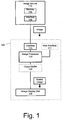
- Figure 1 depicts a system for scaling an image, to produce a scaled image.
- the image will be of a first resolution, while the scaled image will be of a second resolution.
- the scaled image may represent a geometric correction of the image.
- An image processor 120 for scaling the image to produce the scaled image, is coupled to an image source 110 via an interface 115.
- the scaled image is stored in an output buffer 125, prior to releasing the scaled image to an image display unit 130.
- the image processor 120 is in further communication with a user interface 117, for accepting data from a user. In these embodiments, the image processor 120 is enabled to process data received from the user interface 117.
- the interface 115, the image processor 120, and the image display unit 130 are elements of an apparatus 140, however in other embodiments, the interface 115, the image processor 120, and the image display unit 130 (and the output buffer 125, and the user interface 117 if present) may be distributed between other apparatus (not depicted).
- the image processor 120, the interface 115, the output buffer 125 and the user interface 117 may be elements of a computing device for image and/or computational processing, and the image display unit 130 may be a standalone apparatus.
- the apparatus 140 may further comprise the image source 110.
- the image source 110 may comprise a device for providing displayable images including, but not limited to, devices for generating and/or storing images.
- the image source 110 may comprise a computing device, for example a personal computer, a server or an image server, while in other embodiments, the image source 110 may comprise a camera for producing the image, including but not limited to a digital camera, an analog video camera, a digital video camera, or a combination of the above.
- the image may be stored in a file, or in random or sequentially accessed memory. In some of these embodiments, the file may be stored on portable media, such a magnetic disc, an optical disc (e.g. a DVD or CD), or a USB flash memory, and the like.
- the image source 110 may comprise a portable media player (not depicted).
- a portable media player include a CD player, a DVD player, a USB port combined with software to play image files stored on a USB flash memory, and the like.
- the image source 110 may further comprise a memory 105 for storing the image prior to transmitting the image to the image processor 120, however in other embodiments the image is not stored in memory and is transmitted to the image processor 120 upon production of the image, for example as a video signal (described below).
- the image source 110 comprises an interface 106 for coupling the image source 110 to the image processor 120.
- the interface 110 may comprise a wired or a wireless interface (described below).
- the image may comprise a still image or a video image.
- the image may be stored in a memory, for example the memory 105, and can be accessed directly from a memory as an array of pixels, or it can be received and processed as a stream of pixels.
- the image may also comprise an analog image or a digital embodiment, where the image is stored in a file, the file may comprise a digital file.
- the digital file may comprise a still image digital file in any format, including but not limited to, a TIFF file, a JPEG file, or a GIF file etc.
- the digital file may comprise a video image digital file, including but not limited to MPEG formats, including but not limited to MPEG-1, MPEG-2, MPEG-3 and MPEG-4, and other formats, including but not limited to H.261, H.263, H.264, Theora, D1, D2, D3, D5, D9, DV, MiniDV, DVCAM, DVCPRO etc.).
- the image may comprise a data stream of a suitable format that is transmitted to the apparatus 140, for example a video stream transmitted to the apparatus 140.
- the image may comprise an analog image or a digital image, for example an analog video stream or a digital video stream respectively.
- the image comprises a digital image
- the image is comprised of an array of pixels, the pixels arranged into rows and columns, each pixel representing a small area of the image, as known to one of skill in art.
- the analog image is first digitized (i.e. converted) to an array of pixels prior to scaling the image to produce the scaled image.
- Each pixel is associated with pixel data which, when received by the image display unit 130, will enable the image display unit 130 to display each pixel at a location on the image display unit 130, and hence display the image.
- a pixel position is associated with each pixel, such that the image display unit 130 understands where to display each pixel.
- the pixel data comprises the pixel position
- the pixel position is defined by the format of the image.
- the pixel position may be understood by the order in which the pixel data is stored within the digital file.
- the pixel position may be understood by the order in which the pixel data is received within the video stream.
- pixel data associated with the top left pixel of the image is stored first within the data file, or transmitted in the data stream, with subsequent pixels in the top row stored in sequence.
- the next pixel data stored is associated with the pixel immediately beneath the last pixel in the top row (i.e. the right most pixel in the second row).
- Remaining pixel data is stored in a similar manner, with pixel data stored row by row proceeding from left to right, and then right to left, across the image, in alternating rows, until the bottom of the image is reached.
- the remaining pixel data is stored with pixel data stored row by row, proceeding from left to right for each row.
- the pixel data comprises data which will instruct the image display unit 130 of the intensity of the pixel.
- the pixel data 130 comprises data which will instruct the image display unit 130 of the absolute intensity of the pixel, while in other embodiments, comprises data which will instruct the image display unit 130 of the relative intensity of the pixel.
- the pixel data further comprises data which will instruct the image display unit 130 of the color of the pixel.
- the pixel data comprise an index into a table of colors, the table of colors stored at either the image processor 120 or the image display unit 130.
- the pixel data may comprise an absolute intensity value for each color. The intensity for each color can have any bit depth or resolution.
- the intensity & color data can be in RGB (Red, Green, Blue) format or with the colors combined in any other way (YPbPr etc.).
- data to be shared across pixels or lines as in 4:2:2 format) where pairs of pixels share the same color.
- the pixel data comprises data in 10bit RGB format in gamma space and in 16bit in linear space, such that in linear space pixel data for all three colors (RGB) comprise 48bits/pixels.
- the pixel data comprises an 8 bit number, the 8 bit number representative of the intensity of the pixel as it is to be displayed.
- the scaled image is comprised of an array of pixels, the pixels arranged into rows and columns, and each pixel representing a small area of the scaled image.
- the interface 115 is enabled to couple the image processor 120 to the image source 110, and may comprise any interface that allows an image in any format to be transferred from the image source 110, including a wired or a wireless interface.
- the interface 115 may include, but is not limited to, a Digital Visual Interface (DVI), a High Definition Multimedia Interface (HDMI), an analog RGB interface, a YPbPr interface, a Composite interface, an Separate-Video (S-Video) interface, a serial interface (e.g. RS-232 or other serial interface), a parallel interface (e.g. Parallel SCSI or other parallel interface), an ethernet interface, or a combination of the above.
- DVI Digital Visual Interface
- HDMI High Definition Multimedia Interface
- RGB analog RGB interface
- YPbPr interface a Composite interface
- S-Video Separate-Video
- serial interface e.g. RS-232 or other serial interface
- a parallel interface e.g. Parallel SCSI or other parallel interface
- an ethernet interface or a
- the interface 115 may include, but is not limited to, a WiFi Interface, a WiMax Interface, a wireless telephone interface (e.g. CDMA, 1X, EVDO, GSM, UTMS etc.), or a combination of the above.
- a WiFi Interface e.g. CDMA, 1X, EVDO, GSM, UTMS etc.
- a wireless telephone interface e.g. CDMA, 1X, EVDO, GSM, UTMS etc.
- the interface 106 may comprise a wired or a wireless interface, and may be similar to the interface 115.
- the image processor 120 comprises a processor for processing images, including but limited to scaling the image to produce the scaled image. Other functions of the image processor 120 may include an on screen display (OSD), a color space converter, edge blending, image filters, including noise filters, sharpness filters and Nyquist filters, and the like. In embodiments where the image comprises an analog image, the image processor 120 may be further enabled to convert the analog image to a digital image prior to scaling the image. In some embodiments, the image processor 120 may be in communication with a central processing unit (not depicted) for controlling other components of the apparatus 140 (if applicable) and/or the image display unit 130, and/or other components of the system. In other embodiments, the image processor 120 may be a component of the central processing unit.
- OSD on screen display
- edge blending image filters, including noise filters, sharpness filters and Nyquist filters, and the like.
- image processor 120 may be further enabled to convert the analog image to a digital image prior to scaling the image.
- the image processor 120 may be in communication with
- the output buffer 125 may be a separate element from the image processor 120 (as depicted), while in other embodiments, the image processor 120 may comprise the output buffer 125 (not depicted). In any event, the output buffer 125 may store the scaled image, or a portion of the scaled image, prior to releasing the scaled image to the image display unit 130. In these embodiments, the image processor 120 may scale the image in portions, producing portions of the scaled image in a sequence. In a non-limiting example, in some embodiments, the image processor 120 may scale the image row by row, hence producing the scaled image row by row. As each row of the scaled image is produced, it may be released to the output buffer 125. In embodiments where the image comprises a video image, the image processor 120 may scale the image frame by frame, hence producing the scaled image frame by frame. As each frame of the scaled image is scaled, it may be released to the output buffer 125.
- the portions of the scaled image may be stored at the output buffer 125, and released to the image display unit 130 when all of the portions, or a sufficient number of portions, of the scaled image are received.
- the output buffer 125 may further assemble the scaled image prior to releasing the scaled image to the image display unit 130
- the image display unit 130 comprises a device for displaying images, including but not limited to the scaled image.
- the image display unit 130 may comprise a digital display apparatus including, but not limited to, a digital projector apparatus, and a digital display, for example a liquid crystal display or a plasma display.
- the image display unit 130 will generally be configured to display images of only certain resolutions, hence the need to scale the image to the scaled image for display by the image display unit 130.
- the digital display apparatus comprises a digital projector apparatus
- the digital projector apparatus may comprise a projector apparatus for projecting images onto a surface, including a projection television screen.
- the image may be of a resolution which is displayable by the image display unit 130.
- a portion of the image may be scaled by the image processor 120 to account for the geometric corrections required when projecting the scaled image onto an irregular surface (described below).
- the image display unit 130 may comprise an analog image display apparatus for example a television, or monitor, comprising a cathode ray tube (CRT).
- the image display unit 130 may be further enabled to convert the generally digital scaled image to an analog image for display.
- the image processor 120 may be enabled to convert the generally digital scaled image to an analog image prior to releasing the scaled image to the image display unit 130.
- the apparatus 140 may comprise a device which incorporates the interface 114, the image processor 120, the output buffer 125 (if present), the user interface 117 (if present) and the image display unit 130.
- the apparatus 140 may comprise a digital projector, as sold Christie Digital Systems Canada, Inc., 809 Wellington St. N., Kitchener, Ontario N2G 4Y7.
- a method of scaling the image to produce the scaled image is now described with reference to Figure 2 .
- the method of Figure 2 may be performed by the image processor 120.
- the method of Figure 2 may also be performed in a distributed manner by different elements of the system depicted in Figure 1 .
- each pixel in the image i.e. image pixels
- the concept is to map all of the energy of the image pixels to at least one of the closest pixels in the scaled image (i.e. scaled pixels).
- the energy of the image pixel is divided into parts, with each part assigned to a different scaled pixel, where it is added to the energy contributed by other image pixels. How the energy of an image pixel is assigned is based on the relative overlap area between the image pixels and the scaled pixels. In some embodiments, the relative overlap area is determined by the boundaries of the image pixels, relative to the boundaries of the scaled pixels. Within some embodiments, it is assumed that there are no spaces between the pixels of either the image or the scaled image.
- step 210 the image is received, for example from the image source 110.
- a map is created between each scaled pixel and each image pixel.
- creating the map comprises determining the start boundary of the first pixel in each row or column of each of the image and the scaled image, and determining the end boundary of the first pixel in each row or column of each of the image and the scaled image, and assuming that the start and end boundaries align.
- the boundaries of each image pixel are then determined relative to the boundaries of each scaled pixel, and the boundaries of each scaled pixel are determined relative to the boundaries of each image pixel.
- the relative positions of the boundaries are depicted as dotted lines.
- step 215 may follow step 220.
- an energy parameter of each image pixel is determined.
- the energy parameter may comprise the absolute energy of an image pixel, while in other embodiments, the energy parameter may comprise the relative energy of an image pixel.
- determining the relative energy of an image pixel is sufficient for processing described in further steps in the method of Figure 2 , as the intensity value for a pixel is generally proportional to the energy of a pixel, as known to one of skill in the art.
- the absolute intensity (and hence the energy) of an image pixel may be dependent on the image display unit 130.
- the energy of a pixel is proportional to the intensity.
- the energy parameter of each image pixel may be determined in a single step, while in other embodiments the energy parameter of each image pixel may be performed concurrently with other processing steps.
- the energy parameter of an image pixel may be determined by integrating the area under a curve of intensity vs. area (i.e. pixel intensity profile) for each image pixel.
- the energy of the pixel can be assumed to be distributed evenly over the area of the image pixel.
- the intensity profile across the area of the pixel can assume many shapes and can overlap with neighbouring pixels for a smoother image.
- the shape of the pixel can be arbitrary as in bi-linear or Gaussian curves, or it can be dependent on the intensity of any other nearby pixels, as is the case for edge or object detection methods or filters.
- the pixel data comprises data which will instruct the image display unit 130 of the intensity of each pixel.
- the pixel data may further comprise information describing the pixel intensity profile across the area of the pixel.
- a constant pixel intensity profile may be used.
- non-constant pixel intensity profiles may be used to correct for pixelation artefacts (discussed below).
- integrating the area under a curve of intensity vs. area for each image pixel may comprise: determining an area of each image pixel; determining the intensity of each image pixel; and multiplying the area by the intensity of the image pixel.
- the area under the intensity curve (or the volume under the intensity surface) must be integrated over the area where the scaled pixel overlaps with the image pixel.
- the area of the image pixel may be an absolute area, while in other embodiments, the area of the image pixel may be a relative area (see below).
- FIG. 3 depicts an image comprised of a 1x5 array (i.e. one row and five columns) which is to be scaled to produce a scaled image comprised of a 1x4 array (i.e. one row and four columns).
- the image and the scaled image are plotted as intensity vs. area for each pixel.
- the energy present in the 1x5 array must be divided and assigned to the scaled pixels of the 1x4 array.
- each pixel in the 1x4 array is assumed to have an area that is 5/4 (125%) larger than each pixel in the 1x5 array. In some embodiments, spaces that may exist between pixels are ignored, as depicted.
- each image pixel may be assigned a relative area of 1 areal unit.
- the relative area of the scaled pixels would be 1.25 areal units (i.e. 5/4 times 1).
- step 250 the overlap area between the image pixels and the scaled pixels will be determined.
- an areal unit which will ensure that the boundaries of the each of the image pixels and the scaled pixels, overlap an areal unit boundary.
- an areal unit is chosen such that each of the image pixels and each of the scaled pixels is an integer number of areal units.
- each image pixel is assigned an area of 4 areal units
- each scaled pixel then has an area of 5/4 times the area of the image pixels, or 5 areal units.
- the areal unit which results in the relative area being an integer number of areal units for both the image pixels and the scaled pixels is known as a subpixel.
- the relative area of each image pixel is 4 subpixels, and the relative area of each scaled pixel is 5 subpixels. It is noted, then, that each of the arrays will have an equal number of subpixels.
- the number of subpixels assigned to each image pixel will be determined based on the relative resolution between the image and the scale image, as described above.
- the image processor 120 may assign a fixed number of subpixels, N, to each image pixel which arrives at the image processor 120.
- N a fixed number of subpixels
- Each scaled pixel is then expressed as an integer multiple of 1/N subpixels, such that the boundaries of the scaled pixels will always fall on a subpixel boundary of the image pixels.
- N the number of subpixels assigned to each image pixel which arrives at the image processor 120.
- N the image processor 120 may assign a fixed number of subpixels, N, to each image pixel which arrives at the image processor 120.
- Each scaled pixel is then expressed as an integer multiple of 1/N subpixels, such that the boundaries of the scaled pixels will always fall on a subpixel boundary of the image pixels.
- N In general a larger N, will better result in meeting this condition, and each row (or column) of the image and the corresponding
- the number of subpixels assigned to each scaled pixel may vary, to correct for these variations, and to ensure that each row (or column) has an equal number of subpixels as the corresponding row (or column) in the image. For example, some of the scaled pixels may be assigned a first number of subpixels, while other scaled pixels may be assigned a second number of subpixels.
- the intensity of each image pixel must also be determined.
- the pixel data comprises data which will instruct the image display unit 130 of the intensity of the pixel
- the intensity may be determined by processing the pixel data associated with each image pixel.
- the intensity of each image pixel is multiplied by the relative area of each image pixel.
- Image Pixel #1 has an area of 4 areal units and the intensity of Image Pixel #1 is 1 intensity unit.
- the energy parameter of Image Pixel #1 is 4 energy units (depicted in brackets).
- Image Pixel #2 has an area of 4 areal units and the intensity of Image Pixel #2 is 4 intensity units.
- the energy parameter of Image Pixel #2 is 16 energy units (depicted in brackets). Similar calculations are made for the remaining pixels, such that Image Pixel #2 is determined to have 16 energy units, Image Pixel #3 is determined to have 8 energy units, Image Pixel #4 is determined to have 12 energy units, and Image Pixel #5 is determined to have 20 energy units, for a total of 60 energy units.
- the relative overlap area between pixels is determined.
- the relative overlap area is determined by processing the start and end boundaries of both the image pixels and the scaled pixels to determine which pixels overlap. The relative positions of the boundaries are then processed to determine the relative overlap area.
- the entirety of Image Pixel #1 falls within the boundaries of Scaled Pixel #1, hence the relative overlap area between Image Pixel #1 and Scaled Pixel #2 is 4 out of 4 areal units (depicted as 4/4 in Figure 3 ), or " 1 ".
- 1 out of 4 areal units of Image Pixel #2 overlaps Scaled Pixel #1, and hence the relative overlap area between Image Pixel #1 and Scaled Pixel #2 is 1 ⁇ 4.
- step 250 may also proceed step 220.
- the energy parameter of each image pixel is assigned to the scaled pixels based on the relative overlap area: the fraction of each image pixel that overlaps each scaled pixel is used to determine the fraction of the energy parameter from each image pixel that is assigned to each scaled pixel.
- the energy parameter of Image Pixel #1 is 4 energy units, while the relative overlap area with Scaled Pixel #1 is "1". Hence 100% of the energy parameter of Image Pixel #1 is assigned to Scaled Pixel #1.
- the energy parameter of Image Pixel #1 is 16 energy units, while the relative overlap area with Scaled Pixel #1 is 1 ⁇ 4, and the relative overlap area with Scaled Pixel #1 is 3 ⁇ 4.
- the scaled image is released to the image display unit 130.
- the scaled image may be released to the output buffer 125 prior to releasing the image to the image display unit 130.
- portions of the image may be released to the output buffer 125 prior to releasing the image to the image display unit 130.
- the scaled pixel is released to the output buffer 125, to await the arrival of the remaining scaled pixels.
- the scaled image may not be released to the image display unit 130, but may be saved to a memory (not depicted) for later transmission or transport to the image display device 130, or another image display device.
- the image pixels may be processed as an array using linear algebra computations, while in other embodiments, each image pixel may be processed in a sequence, for example in embodiments where the image is received at the image processor 120 as a data stream. In some of these embodiments the image is received at the image processor 120 a line at a time, hence some a priori knowledge of the resolution of the image may be known to the image processor 120.
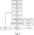
- Figure 4 depicts a method for scaling an image to produce a scaled image, by processing image pixels in a sequence, and is a particular embodiment of the method of Figure 2 .
- the method of Figure 4 may be performed by the image processor 120.
- the method of Figure 4 may also be performed in a distributed manner by different elements of the system depicted in Figure 1 .
- the resolution of the scaled pixels is known, for example the resolution of the scaled pixels may comprise a resolution of the image display unit 130 and/or a desired geometric correction.
- some a priori knowledge of the resolution of the image is assumed, for example the resolution of each line.
- the image is received according to a standard, such that the position of each pixel in the image is known.
- the top row of the image is the first row to be broadcast or transmitted, and further the pixels are generally transmitted left to right.
- the image processor 120 will generally understand that the first image pixel received will be the image pixel that is in the top left hand corner of the image, etc.
- a number of subpixels, N, which are to be assigned to each image pixel is determined.
- the number of subpixels assigned to each image pixel may be a fixed number for each image which arrives at the image processor 120, or may be determined based on the scaling.
- a number of subpixels, M j is assigned to the first scaled pixel SP j .
- the first scaled pixel SP j may be chosen based on the a priori knowledge of the first image pixel that is to be processed, and/or the desired scaling. In a non-limiting example, if the first image pixel to be scaled has a given position in the image (e.g. the upper left corner), then in some embodiments the first scaled pixel SP j is in the corresponding position of the scaled image (i.e. the upper left corner). However in embodiments where the scaled image is representative of a geometric correction of the image (discussed below), the first scaled pixel SPj may be in a different position than the corresponding position of the scaled image.
- the number of subpixels M j assigned to SP j may be chosen in a manner similar to that described above.
- an image pixel IP i is received.
- an energy parameter of IP i is determined in a manner similar to that described above.
- Sp j is mapped to IPi to determine the relative positions of the pixel boundaries for both SP j and IP i , in a manner similar to that described above.
- the relative overlap area between SP j and IP i is determined, and at step 470 at least a portion of the energy parameter of IPi, determined at step 440, is assigned to SP j based on the relative overlap area.
- an image to be scaled comprises a two dimensional array of rows of columns
- scaling of the image to produce the scaled image may be achieved in two applications of the method described in Figure 2 : first by scaling the image in one of a vertical direction or a horizontal direction, to produce an intermediate scaled image; and by then scaling the intermediate scaled image in the other direction to produce the scaled image.
- the columns (or rows) of the image may be scaled first, followed by scaling of the rows (or columns).
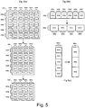
- Figure 5 depicts, under the letter "A", an image 510 comprising pixels, 515a, 515b, etc. arranged into 6 columns, 520a, 520b, 520c, 520d, 520e, 520f and 5 rows, 530a, 530b, 530c, 530d, 530e (i.e. a 6x5 array).
- the image 510 is to be scaled to produce a scaled image 550 comprising pixels, 555a, 555b, etc. arranged into 4 columns, 560a, 560b, 560c, 560d and 3 rows, 570a, 570b, 570c (i.e. a 4x3 array).
- An intermediate scaled image 540 comprising pixels 541a, 541b, etc. arranged into 4 columns, 560a', 560b', 560c', 560d' and 5 rows, 530a', 530b', 530c', 530d', 530e' (i.e. a 4x5 array) is also depicted.
- Each of the image 510, the intermediate scaled image 540, and the scaled image 550 is depicted as it would appear to an observer, each pixel having an absolute area, and space between each pixel.
- Figure 5 further depicts, under the letter "B", the process of scaling each column in the row 530a of the image 510 to produce row 530a' of the intermediate scaled image 540, and the process of scaling each column in the row 560a' of the intermediate scaled image 540 to produce row 560a of the scaled image 550, according to the method of Figure 2 .
- each column of the image 510 is first scaled to produce each column of the intermediate scaled image 540, on a row by row basis.
- row 530a is depicted in a manner similar to the image pixels depicted in Figure 3 , with no spaces between columns.
- each pixel of row 530a' is mapped onto each pixel of row 530a', in a manner similar to that of Figure 3 , and the relative overlap area is determined.
- An energy parameter of each pixel of row 530a is assigned to each pixel in row 530a', based on the relative overlap area. The process is then repeated for each subsequent row of the image 510, to produce the intermediate scaled image 540.
- each row of the intermediate scaled image 540 is scaled to produce each row of the scaled image 550, on a column by column basis.
- row 560a' is depicted in a manner similar to the image pixels depicted in Figure 3 (however, rotated by 90°), with no spaces between rows.
- To scale each row of column 560a' each pixel of column 560a' is mapped onto each pixel of column 560a, in a manner similar to that of Figure 3 , and the relative overlap area is determined. An energy parameter of each pixel of column 560a' is assigned to each pixel in row 560a, based on the overlap area. The process is then repeated for each subsequent column of the intermediate scaled image 540, to produce the scaled image 550.
- the method of Figure 2 may be applied to first the rows and then the columns of the image 510.
- the scaling of the rows and columns may be applied in both dimensions before proceeding to the next pixel, processing each pixel first as a member of one of a row or a column, and subsequently processing the pixel as a member of the other of the row or column.
- the image processor 120 may further comprise a register to save the state of the scaling process of each pixel, as known to one of skill in the art. Data that may be saved to the register may include the current image pixel boundaries, scaled pixel boundaries, relative overlap areas, and the accumulated value of the energy parameter that has been assigned to each of the scaled pixels thus far.
- the method of Figure 2 has been described with respect to uniform scaling of an image to produce a scaled image: in other words, each row, and/or each column, of an image is scaled using the same scaling parameters.
- the method of Figure 2 may also be applied to scaling an image non-uniformly to produce a scaled image, in order to account for geometric corrections; in other words different rows, and/or different columns, may be scaled using different scaling parameters.
- Each pixel may be scaled using different scaling parameters than any of the surrounding pixels.
- an image may be scaled non-uniformly to produce a scaled image, such that when the scaled image is projected onto a non-uniform surface or at an off-perpendicular angle, the projected scaled image appears uniform, to an observer.
- the projected image when an image is projected onto a flat surface from a projector apparatus which is not perpendicular to the horizontal or vertical centerline of the screen (too high or too low, too left or too right), the projected image appears skewed to an observer, such that rectilinear images will appear trapezoidal (or keystoned).
- the image may be scaled non-uniformly prior to producing a scaled image that is itself trapezoidal, such that when the scaled image is projected it appears rectilinear to an observer. This correction is known as a keystone correction.
- the image when an image is projected onto a non-uniform surface such as a curved surface (concave or convex), a domed or spherical surface, a corner, or other non-uniform surface, the image may be scaled non-uniformly to produce a scaled image, such that when the scaled image is projected onto the non-uniform surface, the scaled image appears to be uniform to an observer.
- the nature of the geometric correction applied to an image may be controlled by a user via the user interface 117, while in other embodiments the nature of the geometric correction may be controlled via a computing entity (not depicted) in communication with the image processor 120 via the interface 115, or a computing entity interface (not depicted).
- the image source 110 may comprise the computing entity.
- Figure 6 depicts two non-limiting examples of geometric corrections that may be applied to an image 610 using the method of Figure 2 .
- a keystone geometric correction may be applied to the image 610 to produce the scaled image 620, such that when the scaled image 620 is projected onto a flat surface from a projector apparatus which is above the horizontal perpendicular of the flat surface, the scaled image 620 appears rectilinear to an observer.
- the columns of each row of the image 610 are variably scaled using the method of Figure 2 , such that columns of each successive row in the image 610, from top to bottom, are downscaled to a slightly greater extent than each previous row.
- the image 610 is superimposed, in outline, on the scaled image 620 to indicate the relative scaling of the image 610.
- a curved screen geometric correction may be applied to the image 610 to produce the scaled image 630, such that when the scaled image 630 is projected onto a curved screen via a projector apparatus, the scaled image 630 appears rectilinear to an observer.
- the columns of each row of the image 610 are variably scaled using the method of Figure 2 , such that columns of each successive row in the image 610, from the top to the horizontal centreline of image 610, are downscaled to a slightly lesser extent than each previous row, the process reversing at the horizontal centreline.
- each row of the image 610 are variably scaled using the method of Figure 2 , such that rows of each successive column in the image 610, from left to the vertical centreline of image 610, are downscaled to a slightly lesser extent than each previous column, the process reversing at the vertical centreline.
- the image 610 is superimposed, in outline, on the scaled image 620 to indicate the relative scaling.
- the difference in scaling between each line (row or column) to achieve to achieve the geometric correction may be quite small, for example, less than one pixel, and in some embodiments, less than one subpixel.
- the image processor 120 may further comprise a position counter (including, but not limited to, a high resolution counter), to track the scaled pixel boundaries.
- each pixel may be assigned a size (i.e. an integer number of subpixels) that brings the start and boundaries for the line (row or column), as close as possible to the ideal location.
- each scaled pixel may be assigned a different number of subpixels, as described above, that gradually changes the scaling of successive lines by the desired amount.
- the scaled pixel sizes may alternate between two values.
- a similar effect may be achieved by providing a size dithering function that is applied to successive lines.
- the size dithering function is provided via a table of size values.
- the table of size values may be stored in a memory of the image processor 120 or the memory of another element of Figure 1 , while in other embodiments the table of size values may be stored in a database (not depicted) in communication with the image processor 120.
- the table of size values contains the desired absolute size of each line in the scaled image while, in other embodiments, the table of size values contains the relative size of each line in the scaled image.
- an intensity correction may be applied to the pixels, before, during or after the scaling process, such that the pixels of the scaled image have a different intensity than the pixels of the image.
- a top to bottom keystone correction in which the image is projected upwards towards a flat screen. The uncorrected image appears wider at the top.
- the keystone correction is applied, the top of the image is displayed using fewer pixels, so for the final image to appear uniform those pixels at the top must be brighter so that the total brightness along the top of the image remains constant. This is taken care of automatically when the image pixels are compressed into scaled pixels.
- each image pixel takes all of its energy with it and since the top of the image gets compressed into fewer scaled pixels, those pixels are correspondingly brighter. This is a desirable effect because the geometry corrected image, when displayed on a curved or off-angle surface, will not only appear to have its original shape but also every part of the image will appear to the viewer to have its original intensity. However, when the pixels near the top of the image are at close to 100% intensity, the pixels near the top of the scaled image may be at >100% intensity. This may cause white level crushing, an effect known to one of skill in the art. To avoid this effect, in some embodiments the intensity of the image may be reduced in magnitude proportional to the maximum downscaling used anywhere in the image.
- the intensity of the pixels of the image may be reduced by 80%.
- the entire image is up-scaled an opposite effect occurs where the scaled image is dimmer than it needs to be.
- a similar correction may used in this instance.
- a non-uniform change in the magnitude of the intensity may be applied to pixels of the image, for example in embodiments where the input image is also warped at the source so intensity compensation is not desired.
- the full brightness possible for the final image is desired, even though the brightness is not uniform.
- a gamma transformed image data is common for most images although the exact value of gamma is not always the same.
- the application of the method of Figure 2 to a gamma corrected image will result in artefacts in the scaled image due to the non-linear distribution of intensity that results from the gamma transformation.
- the image prior to scaling the image to produce a scaled image, the image may be transformed back to "linear" space, for example by transforming the image using an inverse gamma function.
- the scaled image may be transformed using a gamma function prior to displaying the scaled image at the image display unit 130.
- the scaled image comprises more pixels than the image.
- artefacts which may exist in the image may be magnified in the scaled image.
- a property of digital images formed from pixels is that the edges of diagonal lines are pixelated (i.e. stepped). When observed from a distance, the pixelation may not be noticeable to a viewer, however the process of upscaling results in a magnification of the pixelation in the scaled image
- this may be corrected by applying an intensity profile correction to the image pixels, prior to scaling the image to produce the scaled image.
- each pixel is assumed to have an intensity profile that is uniform across the area of the pixel.
- the intensity profile of each image pixel may be corrected, as long as the total energy associated with each image pixel remains constant.
- pixels may also be spread out to overlap with neighbouring pixels.
- the energy of each of the image pixels is spread out between adjacent pixels, prior to scaling the image to produce the scaled image. This results in smoothing the pixelation effects in the scaled image.
- the scaled image may appear softer than it would if an intensity profile correction was not applied.
- a sharpening filter may be applied to the scaled image to sharpen the scaled image, prior to displaying the scaled image at the image display unit 130.
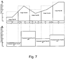
- Figure 7 depicts a non-limiting example of an adjustment to the intensity profile of the pixels of an image.
- the example of Figure 7 is similar to the example of Figure 3 , however a linear adjustment to the intensity profile of each pixel has been applied prior to scaling the image to produce the scaled image.
- each image pixel is assumed to have an intensity profile similar to the intensity profile of each image pixel in Figure 3 (depicted in outline).
- the intensity of each image pixel is determined at the centre point of each image pixel.
- a line is then drawn from the centre point of each of each image pixel to the centre point of each adjacent pixel. Any intensity that lies above this line is reassigned to the adjacent pixel such that the line becomes the new intensity profile for each pixel.
- the area under the line is integrated.
- intensity profile corrections may be applied including using a Gaussian profile for the image intensity and an S-Curve image correction.
- intensity profile corrections may be applied only to areas of the image where transitions (e.g. edges) exist.
- the intensity profile correction may be applied to diagonal transitions/edges.
- Various 1D, 2D or 3D filters can also be applied to create an improved curve prior to integrating the area under it to generate the scaled pixels.
- an intensity profile corrections may be applied to images which are to be downscaled.
- the other types of corrections may be applied to the image, the scaled image or both, to alter the appearance of the scaled image.
- Types of corrections which may be applied include, but are not limited to, sharpening filters, pre-sharpening filters, noise reduction filters, and the like.
- the image may be up-scaled, downscaled, twisted and/or distorted.
- the apparatus described comprises fewer hardware resources than previous techniques, and the method can therefore be implemented less expensively than previous techniques.
- the scaled images resulting from this technique are of very high quality with minimal artefacts and maxim clarity, particularly for moving images.
- the functionality of the image processor 120 may be implemented using pre-programmed hardware or firmware elements (e.g., application specific integrated circuits (ASICs), field programmable gate arrays (FPGAs), electrically erasable programmable read-only memories (EEPROMs), etc.), or other related components.
- ASICs application specific integrated circuits
- FPGAs field programmable gate arrays
- EEPROMs electrically erasable programmable read-only memories
- the functionality of the image processor 120 may be achieved using a computing apparatus that has access to a code memory (not shown) which stores computer-readable program code for operation of the computing apparatus.
- the computer-readable program code could be stored on a medium which is fixed, tangible and readable directly by these components, (e.g., removable diskette, CD-ROM, ROM, fixed disk, USB drive), or the computer-readable program code could be stored remotely but transmittable to these components via a modem or other interface device connected to a network (including, without limitation, the Internet) over a transmission medium.
- the transmission medium may be either a non-wireless medium (e.g., optical or analog communications lines) or a wireless medium (e.g., microwave, infrared, free-space optical or other transmission schemes) or a combination thereof.
Landscapes
- Physics & Mathematics (AREA)
- General Physics & Mathematics (AREA)
- Engineering & Computer Science (AREA)
- Theoretical Computer Science (AREA)
- Image Processing (AREA)
- Controls And Circuits For Display Device (AREA)
- Television Systems (AREA)
- Editing Of Facsimile Originals (AREA)
- Control Of Indicators Other Than Cathode Ray Tubes (AREA)
- Transforming Electric Information Into Light Information (AREA)
Claims (15)
- Verfahren zur Skalierung eines Bildes zur Erzeugung eines skalierten Bildes, wobei das Bild ein Array von Bildpixeln umfasst und das skalierte Bild ein Array von skalierten Pixeln umfasst, wobei das Verfahren Folgendes umfasst,- Erstellen einer Map zwischen dem Array von skalierten Pixeln und dem Array von Bildpixeln unter Verwendung mindestens eines Reihen-Skalierfaktors und mindestens eines Spalten-Skalierfaktors, sodass das Bild ungleichmäßig skaliert ist;- Bestimmen eines Energieparameters jedes Bildpixels in dem Array von Bildpixeln, wobei der Energieparameter absolute Energie oder relative Energie jedes Bildpixels umfasst;- Bestimmen eines Bruchteils eines gegebenen Bildpixels, der ein gegebenes skaliertes Pixel in dem Array von skalierten Pixeln überlappt, bei jedem Bildpixel in dem Array von Bildpixeln;- Verteilen des Energieparameters des gegebenen Bildpixels zwischen skalierten Pixeln, die das gegebene Bildpixel überlappen, während die absolute Energie oder die relative Energie konserviert wird, wobei das Verteilen auf dem Bruchteil beruht, sodass der Energieparameter konserviert wird; und- Freigeben des ungleichmäßig skalierten Bildes an eine ungleichmäßige Bildanzeigeeinheit zur geometrisch korrigierten Projektion.
- Verfahren nach Anspruch 1, worin das Erstellen einer Map zwischen dem Array von skalierten Pixeln und dem Array von Bildpixeln Folgendes umfasst:- Bestimmen des mindestens einen Reihen-Skalierfaktors und des mindestens einen Spalten-Skalierfaktors, die für den Grad der Skalierung zwischen dem Bild und dem skalierten Bild repräsentativ sind;- Verarbeiten jedes Pixels in dem Array von skalierten Pixeln, des mindestens einen Reihen-Skalierfaktors und des mindestens einen Spalten-Skalierfaktors, um ein Array von verarbeiteten skalierten Pixeln zu erzeugen, wobei jedes verarbeitete skalierte Pixel mit einem gegebenen skalierten Pixel in dem Array von skalierten Pixeln, in einer Eins-zu-Eins-Beziehung, assoziiert ist;- Assoziieren jedes verarbeiteten skalierten Pixels in dem Array von verarbeiteten skalierten Pixeln mit einer Position in dem Array von Bildpixeln.
- Verfahren nach Anspruch 2, ferner umfassend das Eliminieren von Räumen zwischen den Bildpixeln in dem Array von Bildpixeln, sodass eine Grenze jedes Bildpixels mit einer Grenze jedes benachbarten Bildpixels ausgerichtet ist, und das Eliminieren von Räumen zwischen den verarbeiteten skalierten Pixeln in dem Array von verarbeiteten skalierten Pixeln, sodass eine Grenze jedes verarbeiteten skalierten Pixels mit einer Grenze jedes benachbarten verarbeiteten skalierten Pixels ausgerichtet ist, wobei das Bild eine erste Auflösung aufweist und das skalierte Bild eine zweite Auflösung aufweist, und das Bestimmen des mindestens einen Reihen-Skalierfaktors und des mindestens einen Spalten-Skalierfaktors das Verarbeiten der ersten Auflösung und der zweiten Auflösung umfasst.
- Verfahren nach Anspruch 3, worin das Array von Bildpixeln eine gegebene Anzahl von Reihen und eine gegebene Anzahl von Spalten umfasst, wobei die erste Auflösung die gegebene Anzahl von Reihen und die gegebene Anzahl von Spalten umfasst, und worin das Array von skalierten Pixeln eine gegebene Anzahl von skalierten Reihen und eine gegebene Anzahl von skalierten Spalten umfasst, wobei die zweite Auflösung die gegebene Anzahl von skalierten Reihen und die gegebene Anzahl von skalierten Spalten umfasst, und das Verarbeiten der ersten Auflösung und der zweiten Auflösung Folgendes umfasst:mindestens eines des Bestimmens eines Verhältnisses zwischen der mindestens einen der gegebenen Anzahl von Reihen und der gegebenen Anzahl von skalierten Reihen, um den mindestens einen Reihen-Skalierfaktor zu erzeugen;und des Bestimmens eines Verhältnisses zwischen der gegebenen Anzahl von Spalten und der gegebenen Anzahl von skalierten Spalten, um den mindestens einen Spalten-Skalierfaktor zu erzeugen.
- Verfahren nach Anspruch 4, ferner umfassend das Bestimmen einer Mehrzahl von Skalierfaktoren, wobei die Mehrzahl von Skalierfaktoren ferner Folgendes umfasst:den mindestens einen Reihen-Skalierfaktor und eine Mehrzahl von Spalten-Skalierfaktoren, einschließlich des mindestens einen Spalten-Skalierfaktors, wobei jeder Spalten-Skalierfaktor mit einer Spalte in dem Array von Bildpixeln assoziiert ist; oder,den mindestens einen Spalten-Skalierfaktor und eine Mehrzahl von Reihen-Skalierfaktoren, einschließlich des mindestens einen Reihen-Skalierfaktors, wobei jeder Reihen-Skalierfaktor mit einer Reihe in dem Array von Bildpixeln assoziiert ist; odereine Mehrzahl von Reihen-Skalierfaktoren, einschließlich des mindestens einen Reihen-Skalierfaktors, wobei jeder Reihen-Skalierfaktor mit einer Reihe in dem Array von Bildpixeln assoziiert ist, und eine Mehrzahl von Spalten-Skalierfaktoren, einschließlich des mindestens einen Spalten-Skalierfaktors, wobei jeder Spalten-Skalierfaktor mit einer Spalte in dem Array von Bildpixeln assoziiert ist.
- Verfahren nach einem der Ansprüche 2 bis 5, worin das Verarbeiten jedes skalierten Pixels in dem Array von skalierten Pixeln, unter Verwendung des mindestens einen Reihen-Skalierfaktors und des mindestens einen Spalten-Skalierfaktors, das proportionale Einstellen eines Bereichsparameters jedes skalierten Pixels in dem Array von skalierten Pixeln um den mindestens einen Reihen-Skalierfaktor und den mindestens einen Spalten-Skalierfaktor umfasst, um das Array von verarbeiteten skalierten Pixeln durch Erhöhen oder Verringern des Bereichsparameters jedes der skalierten Pixel zu erzeugen, um das Array von verarbeiteten skalierten Pixeln zu erzeugen, sodass mindestens eine Grenze des Arrays von verarbeiteten skalierten Pixeln mit mindestens einer Grenze des Arrays von Bildpixeln ausgerichtet ist.
- Verfahren nach Anspruch 6, ferner umfassend das Unterteilen jedes Bildpixels in eine erste gegebene Anzahl von Subpixeln, und worin das proportionale Einstellen eines Bereichsparameters jedes skalierten Pixels in dem Array von skalierten Pixeln um den mindestens einen Reihen-Skalierfaktor und den mindestens einen Spalten-Skalierfaktor das Unterteilen jedes skalierten Pixels in eine zweite gegebene Anzahl von Subpixeln und das Addieren oder Subtrahieren einer ungefähr gleichen Anzahl von Subpixeln zu oder von jedem der skalierten Pixel umfasst, um das Array von verarbeiteten skalierten Pixeln zu erzeugen, worin eine erste Untermenge von verarbeiteten skalierten Pixeln in dem Array von verarbeiteten skalierten Pixeln eine erste ganzzahlige Anzahl von Subpixeln umfasst und eine zweite Untermenge von verarbeiteten skalierten Pixeln in dem Array von verarbeiteten skalierten Pixeln eine zweite ganzzahlige Anzahl von Subpixeln umfasst, und/oder eine Dithering-Funktion benutzt wird, um die erste Untermenge von verarbeiteten skalierten Pixeln und die zweite Untermenge von verarbeiteten skalierten Pixeln zu bestimmen, wobei die Dithering-Funktion eine Tabelle von Größenwerten umfasst und die Größenwerte mindestens eines von relativen Größenwerten und absoluten Größenwerten umfassen.
- Verfahren nach einem der Ansprüche 2 bis 7, worin das Assoziieren jedes verarbeiteten skalierten Pixels, in dem Array von verarbeiteten skalierten Pixeln, mit einer Position in dem Array von Bildpixeln das Bestimmen einer Position jedes verarbeiteten skalierten Pixels in dem Array von verarbeiteten skalierten Pixeln umfasst, wobei die Position jedes verarbeiteten skalierten Pixels in dem Array von verarbeiteten skalierten Pixeln mit der Position in dem Array von Bildpixeln assoziiert ist.
- Verfahren nach Anspruch 8, worin die Position in dem Array von Bildpixeln mit einer Startgrenze und einer Endgrenze assoziiert ist und die Position jedes verarbeiteten skalierten Pixels mindestens eine verarbeitete Startgrenze und mindestens eine verarbeitete Endgrenze umfasst und das Assoziieren jedes verarbeiteten skalierten Pixels in dem Array von verarbeiteten skalierten Pixeln mit einer Position in dem Array von Bildpixeln ferner Folgendes umfasst:Bestimmen einer relativen Position der verarbeiteten Startgrenze zu der Startgrenze;Bestimmen einer relativen Position der verarbeiteten Startgrenze zu der Endgrenze;Bestimmen einer relativen Position der verarbeiteten Endgrenze zu der Startgrenze; undBestimmen einer relativen Position der verarbeiteten Endgrenze zu der Endgrenze; undworin das Bestimmen eines Bruchteils eines gegebenen Bildpixels, der ein gegebenes skaliertes Pixel in dem Array von skalierten Pixeln überlappt, bei jedem Bildpixel in dem Array von Bildpixeln, das Verarbeiten mindestens einer der relativen Position der verarbeiteten Startgrenze zu der Startgrenze, der relativen Position der verarbeiteten Startgrenze zu der Endgrenze, der relativen Position der verarbeiteten Endgrenze zu der Startgrenze und der relativen Position der verarbeiteten Endgrenze zu der Endgrenze umfasst.
- Verfahren nach einem der Ansprüche 1 bis 9, wobei das Bestimmen eines Bruchteils eines gegebenen Bildpixels, der ein gegebenes skaliertes Pixel in dem Array von skalierten Pixeln überlappt, bei jedem Bildpixel in dem Array von Bildpixeln, das Bestimmen des relativen Überlappungsbereichs zwischen dem gegebenen Bildpixel und dem gegebenen skalierten Pixel umfasst.
- Verfahren nach Anspruch 10, worin jedes skalierte Pixel in dem Array von skalierten Pixeln mit einem verarbeiteten skalierten Pixel assoziiert ist, wobei das verarbeitete skalierte Pixel durch Verarbeiten eines skalierten Pixels in dem Array von skalierten Pixeln mit einem Skalierfaktor bestimmt wird, wobei der Skalierfaktor für einen Grad der Skalierung zwischen dem Bild und dem skalierten Bild repräsentativ ist, wobei das Bestimmen des relativen Überlappungsbereichs zwischen dem gegebenen Bildpixel und dem gegebenen skalierten Pixel das Bestimmen des Überlappungsbereichs zwischen dem gegebenen Bildpixel und einem verarbeiteten skalierten Pixel, das mit dem gegebenen skalierten Pixel assoziiert ist, umfasst.
- Verfahren nach einem der Ansprüche 1 bis 11, wobei das Verteilen des Energieparameters des gegebenen Bildpixels zwischen skalierten Pixeln, die das gegebene Bildpixel überlappen, wobei das Verteilen auf dem Bruchteil basiert, das Verarbeiten des Bruchteils und des Energieparameters umfasst.
- Verfahren nach einem der Ansprüche 1 bis 12, ferner umfassend das Empfangen jedes Bildpixels in dem Array von Bildpixeln in einer Sequenz; undworin das Erstellen einer Map zwischen dem Array von skalierten Pixeln und dem Array von Bildpixeln das Bestimmen einer Untermenge von skalierten Pixeln, die ein gegebenes empfangenes Bildpixel überlappen, und das Mappen nur der Untermenge von skalierten Pixeln, die das gegebene empfangene Bildpixel überlappen, auf das gegebene empfangene Bildpixel umfasst; und/oderdas Bestimmen eines Energieparameters jedes Bildpixels in dem Array von Bildpixeln, das Bestimmen eines Bruchteils eines gegebenen Bildpixels, der ein gegebenes nichtskaliertes Pixel in dem Array von skalierten Pixeln überlappt, bei jedem Bildpixel in dem Array von Bildpixeln, und das Verteilen des Energieparameters des gegebenen Bildpixels zwischen skalierten Pixeln, die das gegebene Bildpixel überlappen, wobei das Verteilen auf dem Bruchteil basiert, bei jedem Bildpixel in dem Array von Bildpixeln bei dessen Eintreffen in der Sequenz erfolgen; und/oderdas Array von Bildpixeln eine gegebene Anzahl von Reihen und eine gegebene Anzahl von Spalten umfasst und die Sequenz eine Reihe-für-Reihe-Rastersequenz umfasst, wobei die Reihe-für-Reihe-Rastersequenz Folgendes umfasst:abwechselndes Rastern von links nach rechts und Rastern von rechts nach links; oderRastern von links nach rechts.
- Verfahren nach einem der Ansprüche 1 bis 13, worin die geometrisch korrigierte Projektion eine geometrische Korrektur beinhaltet, die mindestens eine einer Trapezkorrektur, einer Wölbungskorrektur, einer Eckenkorrektur und einer gekrümmten Oberflächenkorrektur umfasst.
- Vorrichtung (140), umfassend,- eine Schnittstelle (115) zur Entgegennahme eines Bildes aus einer Bildquelle (110);- einen Bildprozessor (120) in Kommunikation mit der Schnittstelle (110) zur Skalierung des Bildes zur Erzeugung eines skalierten Bildes, wobei das Bild ein Array von Bildpixeln umfasst und das skalierte Bild ein Array von skalierten Pixeln umfasst; Erstellen einer Map zwischen dem Array von skalierten Pixeln und dem Array von Bildpixeln unter Verwendung mindestens eines Reihen-Skalierfaktors und mindestens eines Spalten-Skalierfaktors, sodass das Bild ungleichmäßig skaliert ist; Bestimmen eines Energieparameters jedes Bildpixels in dem Array von Bildpixeln, wobei der Energieparameter absolute Energie oder relative Energie umfasst; Bestimmen eines Bruchteils eines gegebenen Bildpixels, der ein gegebenes skaliertes Pixel in dem Array von skalierten Pixeln überlappt, bei jedem Bildpixel in dem Array von Bildpixeln; Verteilen des Energieparameters des gegebenen Bildpixels zwischen nichtskalierten Pixeln, die das gegebene Bildpixel überlappen, während die absolute Energie oder die relative Energie konserviert wird, wobei das Verteilen auf dem Bruchteil beruht, sodass der Energieparameter konserviert wird; und- eine ungleichmäßige Bildanzeigeeinheit (130) in Kommunikation mit dem Bildprozessor (120) zum Projizieren des geometrisch korrigierten, ungleichmäßig skalierten Bildes.
Applications Claiming Priority (1)
| Application Number | Priority Date | Filing Date | Title |
|---|---|---|---|
| US11/819,478 US8379066B2 (en) | 2007-06-27 | 2007-06-27 | Method and apparatus for scaling an image to produce a scaled image |
Publications (3)
| Publication Number | Publication Date |
|---|---|
| EP2009591A2 EP2009591A2 (de) | 2008-12-31 |
| EP2009591A3 EP2009591A3 (de) | 2009-09-02 |
| EP2009591B1 true EP2009591B1 (de) | 2019-04-10 |
Family
ID=39831688
Family Applications (1)
| Application Number | Title | Priority Date | Filing Date |
|---|---|---|---|
| EP08011735.1A Active EP2009591B1 (de) | 2007-06-27 | 2008-06-27 | Verfahren und Vorrichtung zur Skalierung eines Bildes zur Erzeugung eines skalierten Bildes |
Country Status (3)
| Country | Link |
|---|---|
| US (1) | US8379066B2 (de) |
| EP (1) | EP2009591B1 (de) |
| JP (2) | JP5744374B2 (de) |
Families Citing this family (21)
| Publication number | Priority date | Publication date | Assignee | Title |
|---|---|---|---|---|
| KR100793284B1 (ko) * | 2007-05-11 | 2008-01-10 | 주식회사 코아로직 | 디지털 영상의 손떨림 보정 장치, 방법 및 상기 방법을프로그램화하여 수록한 컴퓨터로 읽을 수 있는 기록매체 |
| WO2008157417A2 (en) * | 2007-06-13 | 2008-12-24 | Arbor Labs, Inc. | Method, system and apparatus for intelligent resizing of images |
| US9188850B2 (en) * | 2007-09-10 | 2015-11-17 | L-3 Communications Corporation | Display system for high-definition projectors |
| US8013858B2 (en) * | 2007-09-20 | 2011-09-06 | Spx Corporation | Statistical waveform drawing routine |
| US20100128181A1 (en) * | 2008-11-25 | 2010-05-27 | Advanced Micro Devices, Inc. | Seam Based Scaling of Video Content |
| KR20100066957A (ko) * | 2008-12-10 | 2010-06-18 | 삼성전자주식회사 | 디스플레이 장치 및 그 제어방법 |
| GB2470942B (en) * | 2009-06-11 | 2014-07-16 | Snell Ltd | Detection of non-uniform spatial scaling of an image |
| US8897602B2 (en) * | 2009-07-22 | 2014-11-25 | Aptina Imaging Corporation | Imaging system with multiframe scaler |
| JP5350488B2 (ja) * | 2009-11-27 | 2013-11-27 | キヤノン株式会社 | 画像処理装置および画像処理方法 |
| JP5736652B2 (ja) * | 2010-03-09 | 2015-06-17 | セイコーエプソン株式会社 | 画像表示装置および画像表示方法 |
| DE102011076112A1 (de) * | 2011-05-19 | 2012-11-22 | Bayerische Motoren Werke Aktiengesellschaft | Verfahren und Vorrichtung zum Erkennen eines möglichenKollisionsobjektes |
| JP5787637B2 (ja) * | 2011-06-21 | 2015-09-30 | キヤノン株式会社 | 画像処理装置、画像処理方法 |
| US9064312B2 (en) | 2011-09-23 | 2015-06-23 | The Regents Of The University Of California | Augmented reality using projector-camera enabled devices |
| JP6056220B2 (ja) * | 2012-07-02 | 2017-01-11 | セイコーエプソン株式会社 | プロジェクター及びその制御方法 |
| US9626748B2 (en) | 2012-07-02 | 2017-04-18 | Seiko Epson Corporation | Projector and method for controlling the same |
| JP6160034B2 (ja) * | 2012-07-02 | 2017-07-12 | セイコーエプソン株式会社 | プロジェクター及びその制御方法 |
| JP2015127680A (ja) * | 2013-12-27 | 2015-07-09 | スリーエム イノベイティブ プロパティズ カンパニー | 計測装置、システムおよびプログラム |
| US9361554B2 (en) | 2014-09-26 | 2016-06-07 | Ricoh Company, Ltd. | Low overhead near unity scaling technique |
| KR102223792B1 (ko) * | 2014-11-10 | 2021-03-04 | 엘지디스플레이 주식회사 | 영상왜곡 보정장치 및 보정방법, 이를 포함하는 곡면형 표시장치 |
| WO2023111210A1 (en) | 2021-12-17 | 2023-06-22 | F. Hoffmann-La Roche Ag | Combination of oligonucleotides for modulating rtel1 and fubp1 |
| KR102782450B1 (ko) | 2022-12-14 | 2025-03-19 | 주식회사 사피엔반도체 | 표시장치 및 스케일러를 이용한 해상도 조정 방법 |
Family Cites Families (16)
| Publication number | Priority date | Publication date | Assignee | Title |
|---|---|---|---|---|
| US5331430A (en) * | 1991-10-11 | 1994-07-19 | R.R. Donnelley & Sons Company | Electronic high-fidelity screenless conversion system |
| US5426723A (en) * | 1992-03-09 | 1995-06-20 | Spacelabs Medical, Inc. | System and method for scaling graphic images |
| US5489952A (en) * | 1993-07-14 | 1996-02-06 | Texas Instruments Incorporated | Method and device for multi-format television |
| JPH0773302A (ja) | 1993-07-20 | 1995-03-17 | Olympus Optical Co Ltd | 画像情報処理システム |
| US5703621A (en) * | 1994-04-28 | 1997-12-30 | Xerox Corporation | Universal display that presents all image types with high image fidelity |
| US5790714A (en) | 1994-11-01 | 1998-08-04 | International Business Machines Corporation | System and method for scaling video |
| US5644325A (en) * | 1994-12-12 | 1997-07-01 | Auravision Corporation | Digital to analog converter with improved output level control |
| JPH10255033A (ja) | 1997-03-13 | 1998-09-25 | Dainippon Screen Mfg Co Ltd | 画像縮小方法 |
| US7106322B2 (en) * | 2000-01-11 | 2006-09-12 | Sun Microsystems, Inc. | Dynamically adjusting a sample-to-pixel filter to compensate for the effects of negative lobes |
| JP4827213B2 (ja) | 2001-03-12 | 2011-11-30 | 株式会社メガチップス | 画像補正装置および画像補正方法 |
| JP3959740B2 (ja) | 2001-07-30 | 2007-08-15 | ソニー株式会社 | プロジェクタおよび画像補正方法 |
| DE10221389A1 (de) * | 2002-05-14 | 2003-12-04 | Siemens Ag | Verfahren zur Ermittlung eines Pixelwertes eines Pixel aufweisenden Bildes, Gewichtungsmatrix und Recheneinrichtung |
| JP4059031B2 (ja) | 2002-08-09 | 2008-03-12 | セイコーエプソン株式会社 | プロジェクタ |
| US7018050B2 (en) * | 2003-09-08 | 2006-03-28 | Hewlett-Packard Development Company, L.P. | System and method for correcting luminance non-uniformity of obliquely projected images |
| DE10345278B4 (de) * | 2003-09-30 | 2007-03-15 | Thoms, Michael, Dr. | Verfahren und Einrichtung zur Bildbearbeitung |
| JP4887761B2 (ja) | 2005-11-30 | 2012-02-29 | ブラザー工業株式会社 | 画像処理プログラム及び画像処理装置 |
-
2007
- 2007-06-27 US US11/819,478 patent/US8379066B2/en active Active
-
2008
- 2008-06-25 JP JP2008166103A patent/JP5744374B2/ja not_active Expired - Fee Related
- 2008-06-27 EP EP08011735.1A patent/EP2009591B1/de active Active
-
2013
- 2013-09-20 JP JP2013194921A patent/JP5806269B2/ja active Active
Non-Patent Citations (1)
| Title |
|---|
| None * |
Also Published As
| Publication number | Publication date |
|---|---|
| EP2009591A3 (de) | 2009-09-02 |
| JP5806269B2 (ja) | 2015-11-10 |
| JP5744374B2 (ja) | 2015-07-08 |
| JP2009065639A (ja) | 2009-03-26 |
| US20090002398A1 (en) | 2009-01-01 |
| EP2009591A2 (de) | 2008-12-31 |
| JP2014057314A (ja) | 2014-03-27 |
| US8379066B2 (en) | 2013-02-19 |
Similar Documents
| Publication | Publication Date | Title |
|---|---|---|
| US8379066B2 (en) | Method and apparatus for scaling an image to produce a scaled image | |
| US11803948B2 (en) | Display management for high dynamic range images | |
| RU2728845C1 (ru) | Устройство и способ улучшения обмена данными изображения на основе нелинейности восприятия яркости между разными возможностями отображения | |
| EP3552178B1 (de) | Systeme und verfahren zur anpassung von videoverarbeitungskurven für bilder mit hohem dynamikbereich | |
| USRE39214E1 (en) | Blending text and graphics for display | |
| US20020145610A1 (en) | Video processing engine overlay filter scaler | |
| US20170206689A1 (en) | Image distortion compensation display device and image distortion compensation method using the same | |
| GB2499635A (en) | Image processing for projection on a projection screen | |
| US8440955B2 (en) | Method for spatial smoothing in a shader pipeline for a multi-projector display | |
| JP2004507987A (ja) | 光学関数生成器を使用するシームレスなタイル式ディスプレイのための電子較正 | |
| KR101267304B1 (ko) | 듀얼 변조 디스플레이들에서의 전력 소모를 감소시키기 위한 방법들 및 시스템들 | |
| WO2007018624A1 (en) | Image adaptation system and method | |
| US8396322B1 (en) | Optical distortion correction in digital video processing applications | |
| US8269804B2 (en) | Image display apparatus and method for correcting color signals based on a sub-pixel location and a position of a viewer | |
| US10178359B2 (en) | Macropixel processing system, method and article | |
| US12586149B2 (en) | Mixed reality recording of foveated display content systems and methods | |
| US8189111B2 (en) | Apparatus and method for image processing in spatial light modulated display systems | |
| JP2006165950A (ja) | 画像処理装置及び画像処理方法 | |
| CN1957606B (zh) | 改进由空间光调制显示系统提供的图像的方法和装置 | |
| Tsai et al. | Generating a multiresolution display by integrating multiple projectors | |
| US9811920B2 (en) | Macropixel processing system, method and article | |
| US10068342B2 (en) | Macropixel processing system, method and article | |
| TW202143214A (zh) | 顯示器驅動裝置及驅動方法 | |
| JP2011199712A (ja) | 映像処理装置および映像表示装置 |
Legal Events
| Date | Code | Title | Description |
|---|---|---|---|
| PUAI | Public reference made under article 153(3) epc to a published international application that has entered the european phase |
Free format text: ORIGINAL CODE: 0009012 |
|
| AK | Designated contracting states |
Kind code of ref document: A2 Designated state(s): AT BE BG CH CY CZ DE DK EE ES FI FR GB GR HR HU IE IS IT LI LT LU LV MC MT NL NO PL PT RO SE SI SK TR |
|
| AX | Request for extension of the european patent |
Extension state: AL BA MK RS |
|
| PUAL | Search report despatched |
Free format text: ORIGINAL CODE: 0009013 |
|
| AK | Designated contracting states |
Kind code of ref document: A3 Designated state(s): AT BE BG CH CY CZ DE DK EE ES FI FR GB GR HR HU IE IS IT LI LT LU LV MC MT NL NO PL PT RO SE SI SK TR |
|
| AX | Request for extension of the european patent |
Extension state: AL BA MK RS |
|
| 17P | Request for examination filed |
Effective date: 20100205 |
|
| 17Q | First examination report despatched |
Effective date: 20100301 |
|
| AKX | Designation fees paid |
Designated state(s): AT BE BG CH CY CZ DE DK EE ES FI FR GB GR HR HU IE IS IT LI LT LU LV MC MT NL NO PL PT RO SE SI SK TR |
|
| GRAP | Despatch of communication of intention to grant a patent |
Free format text: ORIGINAL CODE: EPIDOSNIGR1 |
|
| STAA | Information on the status of an ep patent application or granted ep patent |
Free format text: STATUS: GRANT OF PATENT IS INTENDED |
|
| INTG | Intention to grant announced |
Effective date: 20180528 |
|
| GRAJ | Information related to disapproval of communication of intention to grant by the applicant or resumption of examination proceedings by the epo deleted |
Free format text: ORIGINAL CODE: EPIDOSDIGR1 |
|
| STAA | Information on the status of an ep patent application or granted ep patent |
Free format text: STATUS: EXAMINATION IS IN PROGRESS |
|
| INTC | Intention to grant announced (deleted) | ||
| GRAP | Despatch of communication of intention to grant a patent |
Free format text: ORIGINAL CODE: EPIDOSNIGR1 |
|
| STAA | Information on the status of an ep patent application or granted ep patent |
Free format text: STATUS: GRANT OF PATENT IS INTENDED |
|
| INTG | Intention to grant announced |
Effective date: 20181219 |
|
| GRAS | Grant fee paid |
Free format text: ORIGINAL CODE: EPIDOSNIGR3 |
|
| GRAA | (expected) grant |
Free format text: ORIGINAL CODE: 0009210 |
|
| STAA | Information on the status of an ep patent application or granted ep patent |
Free format text: STATUS: THE PATENT HAS BEEN GRANTED |
|
| AK | Designated contracting states |
Kind code of ref document: B1 Designated state(s): AT BE BG CH CY CZ DE DK EE ES FI FR GB GR HR HU IE IS IT LI LT LU LV MC MT NL NO PL PT RO SE SI SK TR |
|
| REG | Reference to a national code |
Ref country code: GB Ref legal event code: FG4D |
|
| REG | Reference to a national code |
Ref country code: CH Ref legal event code: EP Ref country code: AT Ref legal event code: REF Ref document number: 1119710 Country of ref document: AT Kind code of ref document: T Effective date: 20190415 |
|
| REG | Reference to a national code |
Ref country code: IE Ref legal event code: FG4D |
|
| REG | Reference to a national code |
Ref country code: DE Ref legal event code: R096 Ref document number: 602008059642 Country of ref document: DE |
|
| REG | Reference to a national code |
Ref country code: NL Ref legal event code: MP Effective date: 20190410 |
|
| REG | Reference to a national code |
Ref country code: LT Ref legal event code: MG4D |
|
| REG | Reference to a national code |
Ref country code: AT Ref legal event code: MK05 Ref document number: 1119710 Country of ref document: AT Kind code of ref document: T Effective date: 20190410 |
|
| PG25 | Lapsed in a contracting state [announced via postgrant information from national office to epo] |
Ref country code: NL Free format text: LAPSE BECAUSE OF FAILURE TO SUBMIT A TRANSLATION OF THE DESCRIPTION OR TO PAY THE FEE WITHIN THE PRESCRIBED TIME-LIMIT Effective date: 20190410 |
|
| PG25 | Lapsed in a contracting state [announced via postgrant information from national office to epo] |
Ref country code: FI Free format text: LAPSE BECAUSE OF FAILURE TO SUBMIT A TRANSLATION OF THE DESCRIPTION OR TO PAY THE FEE WITHIN THE PRESCRIBED TIME-LIMIT Effective date: 20190410 Ref country code: SE Free format text: LAPSE BECAUSE OF FAILURE TO SUBMIT A TRANSLATION OF THE DESCRIPTION OR TO PAY THE FEE WITHIN THE PRESCRIBED TIME-LIMIT Effective date: 20190410 Ref country code: ES Free format text: LAPSE BECAUSE OF FAILURE TO SUBMIT A TRANSLATION OF THE DESCRIPTION OR TO PAY THE FEE WITHIN THE PRESCRIBED TIME-LIMIT Effective date: 20190410 Ref country code: LT Free format text: LAPSE BECAUSE OF FAILURE TO SUBMIT A TRANSLATION OF THE DESCRIPTION OR TO PAY THE FEE WITHIN THE PRESCRIBED TIME-LIMIT Effective date: 20190410 Ref country code: PT Free format text: LAPSE BECAUSE OF FAILURE TO SUBMIT A TRANSLATION OF THE DESCRIPTION OR TO PAY THE FEE WITHIN THE PRESCRIBED TIME-LIMIT Effective date: 20190910 Ref country code: NO Free format text: LAPSE BECAUSE OF FAILURE TO SUBMIT A TRANSLATION OF THE DESCRIPTION OR TO PAY THE FEE WITHIN THE PRESCRIBED TIME-LIMIT Effective date: 20190710 Ref country code: HR Free format text: LAPSE BECAUSE OF FAILURE TO SUBMIT A TRANSLATION OF THE DESCRIPTION OR TO PAY THE FEE WITHIN THE PRESCRIBED TIME-LIMIT Effective date: 20190410 |
|
| PG25 | Lapsed in a contracting state [announced via postgrant information from national office to epo] |
Ref country code: PL Free format text: LAPSE BECAUSE OF FAILURE TO SUBMIT A TRANSLATION OF THE DESCRIPTION OR TO PAY THE FEE WITHIN THE PRESCRIBED TIME-LIMIT Effective date: 20190410 Ref country code: GR Free format text: LAPSE BECAUSE OF FAILURE TO SUBMIT A TRANSLATION OF THE DESCRIPTION OR TO PAY THE FEE WITHIN THE PRESCRIBED TIME-LIMIT Effective date: 20190711 Ref country code: LV Free format text: LAPSE BECAUSE OF FAILURE TO SUBMIT A TRANSLATION OF THE DESCRIPTION OR TO PAY THE FEE WITHIN THE PRESCRIBED TIME-LIMIT Effective date: 20190410 Ref country code: BG Free format text: LAPSE BECAUSE OF FAILURE TO SUBMIT A TRANSLATION OF THE DESCRIPTION OR TO PAY THE FEE WITHIN THE PRESCRIBED TIME-LIMIT Effective date: 20190710 |
|
| PG25 | Lapsed in a contracting state [announced via postgrant information from national office to epo] |
Ref country code: AT Free format text: LAPSE BECAUSE OF FAILURE TO SUBMIT A TRANSLATION OF THE DESCRIPTION OR TO PAY THE FEE WITHIN THE PRESCRIBED TIME-LIMIT Effective date: 20190410 Ref country code: IS Free format text: LAPSE BECAUSE OF FAILURE TO SUBMIT A TRANSLATION OF THE DESCRIPTION OR TO PAY THE FEE WITHIN THE PRESCRIBED TIME-LIMIT Effective date: 20190810 |
|
| REG | Reference to a national code |
Ref country code: DE Ref legal event code: R097 Ref document number: 602008059642 Country of ref document: DE |
|
| PG25 | Lapsed in a contracting state [announced via postgrant information from national office to epo] |
Ref country code: RO Free format text: LAPSE BECAUSE OF FAILURE TO SUBMIT A TRANSLATION OF THE DESCRIPTION OR TO PAY THE FEE WITHIN THE PRESCRIBED TIME-LIMIT Effective date: 20190410 Ref country code: CZ Free format text: LAPSE BECAUSE OF FAILURE TO SUBMIT A TRANSLATION OF THE DESCRIPTION OR TO PAY THE FEE WITHIN THE PRESCRIBED TIME-LIMIT Effective date: 20190410 Ref country code: DK Free format text: LAPSE BECAUSE OF FAILURE TO SUBMIT A TRANSLATION OF THE DESCRIPTION OR TO PAY THE FEE WITHIN THE PRESCRIBED TIME-LIMIT Effective date: 20190410 Ref country code: EE Free format text: LAPSE BECAUSE OF FAILURE TO SUBMIT A TRANSLATION OF THE DESCRIPTION OR TO PAY THE FEE WITHIN THE PRESCRIBED TIME-LIMIT Effective date: 20190410 Ref country code: MC Free format text: LAPSE BECAUSE OF FAILURE TO SUBMIT A TRANSLATION OF THE DESCRIPTION OR TO PAY THE FEE WITHIN THE PRESCRIBED TIME-LIMIT Effective date: 20190410 Ref country code: SK Free format text: LAPSE BECAUSE OF FAILURE TO SUBMIT A TRANSLATION OF THE DESCRIPTION OR TO PAY THE FEE WITHIN THE PRESCRIBED TIME-LIMIT Effective date: 20190410 |
|
| REG | Reference to a national code |
Ref country code: CH Ref legal event code: PL |
|
| PLBE | No opposition filed within time limit |
Free format text: ORIGINAL CODE: 0009261 |
|
| STAA | Information on the status of an ep patent application or granted ep patent |
Free format text: STATUS: NO OPPOSITION FILED WITHIN TIME LIMIT |
|
| 26N | No opposition filed |
Effective date: 20200113 |
|
| REG | Reference to a national code |
Ref country code: BE Ref legal event code: MM Effective date: 20190630 |
|
| PG25 | Lapsed in a contracting state [announced via postgrant information from national office to epo] |
Ref country code: TR Free format text: LAPSE BECAUSE OF FAILURE TO SUBMIT A TRANSLATION OF THE DESCRIPTION OR TO PAY THE FEE WITHIN THE PRESCRIBED TIME-LIMIT Effective date: 20190410 |
|
| PG25 | Lapsed in a contracting state [announced via postgrant information from national office to epo] |
Ref country code: IE Free format text: LAPSE BECAUSE OF NON-PAYMENT OF DUE FEES Effective date: 20190627 |
|
| PG25 | Lapsed in a contracting state [announced via postgrant information from national office to epo] |
Ref country code: LU Free format text: LAPSE BECAUSE OF NON-PAYMENT OF DUE FEES Effective date: 20190627 Ref country code: SI Free format text: LAPSE BECAUSE OF FAILURE TO SUBMIT A TRANSLATION OF THE DESCRIPTION OR TO PAY THE FEE WITHIN THE PRESCRIBED TIME-LIMIT Effective date: 20190410 Ref country code: LI Free format text: LAPSE BECAUSE OF NON-PAYMENT OF DUE FEES Effective date: 20190630 Ref country code: CH Free format text: LAPSE BECAUSE OF NON-PAYMENT OF DUE FEES Effective date: 20190630 Ref country code: BE Free format text: LAPSE BECAUSE OF NON-PAYMENT OF DUE FEES Effective date: 20190630 |
|
| PG25 | Lapsed in a contracting state [announced via postgrant information from national office to epo] |
Ref country code: CY Free format text: LAPSE BECAUSE OF FAILURE TO SUBMIT A TRANSLATION OF THE DESCRIPTION OR TO PAY THE FEE WITHIN THE PRESCRIBED TIME-LIMIT Effective date: 20190410 |
|
| PG25 | Lapsed in a contracting state [announced via postgrant information from national office to epo] |
Ref country code: MT Free format text: LAPSE BECAUSE OF FAILURE TO SUBMIT A TRANSLATION OF THE DESCRIPTION OR TO PAY THE FEE WITHIN THE PRESCRIBED TIME-LIMIT Effective date: 20190410 Ref country code: HU Free format text: LAPSE BECAUSE OF FAILURE TO SUBMIT A TRANSLATION OF THE DESCRIPTION OR TO PAY THE FEE WITHIN THE PRESCRIBED TIME-LIMIT; INVALID AB INITIO Effective date: 20080627 |
|
| P01 | Opt-out of the competence of the unified patent court (upc) registered |
Effective date: 20230615 |
|
| PGFP | Annual fee paid to national office [announced via postgrant information from national office to epo] |
Ref country code: DE Payment date: 20250521 Year of fee payment: 18 |
|
| PGFP | Annual fee paid to national office [announced via postgrant information from national office to epo] |
Ref country code: GB Payment date: 20250515 Year of fee payment: 18 |
|
| PGFP | Annual fee paid to national office [announced via postgrant information from national office to epo] |
Ref country code: IT Payment date: 20250528 Year of fee payment: 18 |
|
| PGFP | Annual fee paid to national office [announced via postgrant information from national office to epo] |
Ref country code: FR Payment date: 20250523 Year of fee payment: 18 |