EP2008468B1 - Verfahren und vorrichtung zur redundanten videocodierung - Google Patents
Verfahren und vorrichtung zur redundanten videocodierung Download PDFInfo
- Publication number
- EP2008468B1 EP2008468B1 EP07751848A EP07751848A EP2008468B1 EP 2008468 B1 EP2008468 B1 EP 2008468B1 EP 07751848 A EP07751848 A EP 07751848A EP 07751848 A EP07751848 A EP 07751848A EP 2008468 B1 EP2008468 B1 EP 2008468B1
- Authority
- EP
- European Patent Office
- Prior art keywords
- picture
- encoder
- redundant
- decoder
- macroblocks
- Prior art date
- Legal status (The legal status is an assumption and is not a legal conclusion. Google has not performed a legal analysis and makes no representation as to the accuracy of the status listed.)
- Active
Links
Images

Classifications
-
- H—ELECTRICITY
- H04—ELECTRIC COMMUNICATION TECHNIQUE
- H04N—PICTORIAL COMMUNICATION, e.g. TELEVISION
- H04N19/00—Methods or arrangements for coding, decoding, compressing or decompressing digital video signals
-
- H—ELECTRICITY
- H04—ELECTRIC COMMUNICATION TECHNIQUE
- H04N—PICTORIAL COMMUNICATION, e.g. TELEVISION
- H04N19/00—Methods or arrangements for coding, decoding, compressing or decompressing digital video signals
- H04N19/10—Methods or arrangements for coding, decoding, compressing or decompressing digital video signals using adaptive coding
- H04N19/134—Methods or arrangements for coding, decoding, compressing or decompressing digital video signals using adaptive coding characterised by the element, parameter or criterion affecting or controlling the adaptive coding
- H04N19/146—Data rate or code amount at the encoder output
- H04N19/147—Data rate or code amount at the encoder output according to rate distortion criteria
-
- H—ELECTRICITY
- H04—ELECTRIC COMMUNICATION TECHNIQUE
- H04N—PICTORIAL COMMUNICATION, e.g. TELEVISION
- H04N19/00—Methods or arrangements for coding, decoding, compressing or decompressing digital video signals
- H04N19/10—Methods or arrangements for coding, decoding, compressing or decompressing digital video signals using adaptive coding
- H04N19/134—Methods or arrangements for coding, decoding, compressing or decompressing digital video signals using adaptive coding characterised by the element, parameter or criterion affecting or controlling the adaptive coding
- H04N19/154—Measured or subjectively estimated visual quality after decoding, e.g. measurement of distortion
-
- H—ELECTRICITY
- H04—ELECTRIC COMMUNICATION TECHNIQUE
- H04N—PICTORIAL COMMUNICATION, e.g. TELEVISION
- H04N19/00—Methods or arrangements for coding, decoding, compressing or decompressing digital video signals
- H04N19/10—Methods or arrangements for coding, decoding, compressing or decompressing digital video signals using adaptive coding
- H04N19/169—Methods or arrangements for coding, decoding, compressing or decompressing digital video signals using adaptive coding characterised by the coding unit, i.e. the structural portion or semantic portion of the video signal being the object or the subject of the adaptive coding
- H04N19/17—Methods or arrangements for coding, decoding, compressing or decompressing digital video signals using adaptive coding characterised by the coding unit, i.e. the structural portion or semantic portion of the video signal being the object or the subject of the adaptive coding the unit being an image region, e.g. an object
- H04N19/176—Methods or arrangements for coding, decoding, compressing or decompressing digital video signals using adaptive coding characterised by the coding unit, i.e. the structural portion or semantic portion of the video signal being the object or the subject of the adaptive coding the unit being an image region, e.g. an object the region being a block, e.g. a macroblock
-
- H—ELECTRICITY
- H04—ELECTRIC COMMUNICATION TECHNIQUE
- H04N—PICTORIAL COMMUNICATION, e.g. TELEVISION
- H04N19/00—Methods or arrangements for coding, decoding, compressing or decompressing digital video signals
- H04N19/85—Methods or arrangements for coding, decoding, compressing or decompressing digital video signals using pre-processing or post-processing specially adapted for video compression
- H04N19/89—Methods or arrangements for coding, decoding, compressing or decompressing digital video signals using pre-processing or post-processing specially adapted for video compression involving methods or arrangements for detection of transmission errors at the decoder
- H04N19/895—Methods or arrangements for coding, decoding, compressing or decompressing digital video signals using pre-processing or post-processing specially adapted for video compression involving methods or arrangements for detection of transmission errors at the decoder in combination with error concealment
Definitions
- the present invention relates generally to video encoding and decoding and, more particularly, to a method and apparatus for redundant video coding.
- video data can often be missing upon delivery at the decoder end. This can be caused by various reasons such as, for example, network congestion, channel fading and interference, receiver buffer overflow; and so forth.
- error resilience is usually added in various ways to the bit streams by the encoder.
- Redundant slice is a new tool introduced in the International Organization for Standardization/International Electrotechnical Commission (ISO/IEC) Moving Picture Experts Group-4 (MPEG-4) Part 10 Advanced Video Coding (AVC) standard/International Telecommunication Union, Telecommunication Sector (ITU-T) H.264 recommendation (hereinafter the "MPEG-4 AVC standard") to improve the video error robustness.
- Redundant slice provides a way to add source redundancy by a video encoder. With redundant slice coding, a redundant representation of a picture is coded, with possibly different coding parameters than the primary coded picture. At the decoder, when a primary slice is missing but its redundant slice is available, the decoder reconstructs the picture by decoding the redundant slice, and hence recovers part or all of the lost information.
- redundant slice coding The error resilience provided by redundant slice is at the expense of extra bit rate.
- An ineffective design of redundant slice coding can consume a significant amount of bit rate, while only providing limited capability of reducing video distortion.
- the MPEG-4 AVC standard provides syntax for coding of redundant slices, but does not specify what type of information should be included in the coded redundant slice. There is no specified normative behavior in the MPEG-4 AVC standard for encoding or decoding redundant slices.
- a feature of various methods for implementing redundant slice is that not all the bits spent on a redundant slice are effective in reducing delivered video distortion. Some information coded into the redundant slices by the methods can be readily obtained from other parts of the end-to-end system. This causes a waste of bit rate and hence results in a decreased coding efficiency.
- an apparatus includes an encoder for encoding a redundant coded picture corresponding to a source picture by selecting individual blocks in the source picture for inclusion into the redundant coded picture.
- the method includes encoding a redundant coded picture corresponding to a source picture by selecting individual blocks in the source picture for inclusion into the redundant coded picture.
- an apparatus includes a decoder for decoding a redundant coded picture when a primary picture corresponding to the redundant coded picture is unavailable, by forming a concealed picture based on at least one previously coded primary picture and a redundant decoded picture based on the redundant coded picture and combining the concealed picture and the redundant decoded picture to form a reconstructed picture.
- the method includes decoding a redundant coded picture when a primary picture corresponding to the redundant coded picture is unavailable, by forming a concealed picture based on at least one previously coded primary picture and a redundant decoded picture based on the redundant coded picture and combining the concealed picture and the redundant decoded picture to form a reconstructed picture.
- the present invention is directed to a method and apparatus for redundant video coding.
- processor or “controller” should not be construed to refer exclusively to hardware capable of executing software, and may implicitly include, without limitation, digital signal processor (“DSP”) hardware, read-only memory (“ROM”) for storing software, random access memory (“RAM”), and non-volatile storage.
- DSP digital signal processor
- ROM read-only memory
- RAM random access memory
- any switches shown in the figures are conceptual only. Their function may be carried out through the operation of program logic, through dedicated logic, through the interaction of program control and dedicated logic, or even manually, the particular technique being selectable by the implementer as more specifically understood from the context.
- any element expressed as a means for performing a specified function is intended to encompass any way of performing that function including, for example, a) a combination of circuit elements that performs that function or b) software in any form, including, therefore, firmware, microcode or the like, combined with appropriate circuitry for executing that software to perform the function.
- the invention as defined by such claims resides in the fact that the functionalities provided by the various recited means are combined and brought together in the manner which the claims call for. It is thus regarded that any means that can provide those functionalities are equivalent to those shown herein.
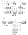
- FIG. 1 an exemplary video encoder to which the present principles may be applied is indicated generally by the reference numeral 100.
- An input to the video encoder 100 is connected in signal communication with a non-inverting input of a combiner 110.
- the output of the combiner 110 is connected in signal communication with a transformer/quantizer 120.
- the output of the transformer/quantizer 120 is connected in signal communication with an entropy coder 140.
- An output of the entropy coder 140 is available as an output of the encoder 100.
- the output of the transformer/quantizer 120 is further connected in signal communication with an inverse transformer/quantizer 150.
- An output of the inverse transformer/quantizer 150 is connected in signal communication with an input of a deblock filter 160.
- An output of the deblock filter 160 is connected in signal communication with reference picture stores 170.
- a first output of the reference picture stores 170 is connected in signal communication with a first input of a motion estimator 180.
- the input to the encoder 100 is further connected in signal communication with a second input of the motion estimator 180.
- the output of the motion estimator 180 is connected in signal communication with a first input of a motion compensator 190.
- a second output of the reference picture stores 170 is connected in signal communication with a second input of the motion compensator 190.
- the output of the motion compensator 190 is connected in signal communication with an inverting input of the combiner 110.
- FIG. 2 an exemplary video decoder to which the present principles may be applied is indicated generally by the reference numeral 200.
- the video decoder 200 includes an entropy decoder 210 for receiving a video sequence.
- a first output of the entropy decoder 210 is connected in signal communication with an input of an inverse quantizer/transformer 220.
- An output of the inverse quantizer/transformer 220 is connected in signal communication with a first non-inverting input of a combiner 240.
- the output of the combiner 240 is connected in signal communication with an input of a deblock filter 290.
- An output of the deblock filter 290 is connected in signal communication with an input of a reference picture stores 250.
- the output of the reference picture stores 250 is connected in signal communication with a first input of a motion compensator 260.
- An output of the motion compensator 260 is connected in signal communication with a second non-inverting input of the combiner 240.
- a second output of the entropy decoder 210 is connected in signal communication with a second input of the motion compensator 260.
- the output of the deblock filter 290 is available as an output of the video decoder 200.
- the present principles are directed to a method and apparatus for redundant video coding.
- a redundant slice is coded at the encoder, the information that can be recovered by the decoder error concealment for its primary coded picture is considered. This information is used by the encoder to effectively reduce the content necessary to be coded in the redundant coded picture, thus resulting in a potential bit rate savings without sacrificing performance.
- a corresponding signaling method is described such that the encoder can efficiently inform the decoder about the different handling of decoded areas when using a redundant slice to reconstruct an original frame.
- an encoder codes a redundant slice for a given frame by selecting whether individual blocks in the given frame should be included in the coding region for the redundant slice.
- the encoder may include a module having a decoder's error concealment algorithm, which is used by the decoder if a primary picture for the given frame were lost.
- the encoder may use the module to select which individual blocks of the given frame are to be included in the coding region for the redundant slice.
- a SKIP mode may be used to indicate that a block is not coded in the redundant slice, and the encoder may be modified to guarantee that the SKIP mode is not used for blocks that are included in the coding region of the redundant coded slice.
- An absolute-difference distortion measure may be used to determine whether a block is included in the coding region.
- the absolute-difference distortion measure may be based on the difference between (1) the result of the error concealment algorithm and (2) an expected result from the decoder if the primary picture were not lost.
- a value of the absolute-difference distortion measure may be compared to a threshold to determine whether to select the block, and the block may be selected to be coded in the redundant coded picture (e.g., the redundant slice) if the result exceeds the threshold.
- the block may have a size of 16x16.
- a decoder is configured to decode redundant slices when the primary picture is not available at the decoder and the redundant coded picture is available.
- the decoder forms an error-concealed picture (a concealed picture) based on previously coded primary pictures, and forms a redundant decoded picture from the redundant slice, and combines these two pictures.
- a SKIP mode may be used for a block to indicate that the concealed picture should be used, and not SKIP mode for the redundant slice.
- the error concealment method may be frame copy or motion copy.
- the block may have a size of 16x16.
- redundant slice is a new error resilience tool introduced in the MPEG-4 AVC standard.
- a primary coded picture PCP
- a redundant coded picture RCP
- a redundant coded picture can be coded by means of a redundant slice. Therefore, when coding a redundant slice, the encoder has the flexibility to use totally different coding parameters other than those of the primary coded picture, such as different coding regions, quantization step sizes, and so forth.
- a redundant slice is only decoded when the primary slice cannot be correctly reconstructed (e.g., the primary slice is missing or corrupted), otherwise the redundant slice is discarded.
- One issue that exists in the use of redundant slices is how to spend bits on a redundant slice efficiently, according to its characteristics, to improve delivered video error resilience.
- One goal may be to reduce the distortion of the delivered video presented to the end viewer, and this goal may be approached from an end-to-end system perspective.
- a redundant slice does not affect the decoding of a primary slice, so the redundant slice cannot impact the source-induced distortion D s,n . Therefore, we focus on utilizing redundant slice coding to lower the channel-induced distortion D c,n .
- E.C . ⁇ utilizes the correlation from spatial or temporal neighbors to reconstruct the damaged region.
- Error concealment often plays an important role in recovering lost information at the decoder.
- error concealment can conceal regions with little or slow-motion effectively, while it may produce artifacts for regions with active and chaotic motion. Nonetheless, except for some special cases such as scene change, a significant amount of information can be recovered by error concealment for a lost frame.
- error concealment algorithms such as frame-repeat and motion-copy algorithms.
- the decoder is expected to recover part of the lost information by error concealment. Therefore, if the encoder knows how the decoder conceals the lost frame, then the recoverable information can be excluded from the redundant slice coding at the encoder without any impact on reducing the distortion. Also, at the decoder, the missing part of the information can be obtained by error concealment.
- f ⁇ n depicts the distortion image produced when the single frame n is lost and concealed by the error concealment operation. It is to be noted that if f ⁇ n is coded into a redundant slice and is available to the decoder, then according the above equation, frame n can be completely recovered even if its primary slice is lost. It is to be also noted that f ⁇ n is obtainable by the encoder after the encoder performs the encoding and the error concealment for frame n .
- each block is of size L ⁇ L in pixels.
- Th 1 the threshold of the pixel absolute difference
- a pixel in f ⁇ n is regarded as distorted whenever its pixel absolute difference value is above Th 1 .
- Th 2 the threshold of the number of pixels and a block is regarded as distorted whenever there are more than Th 2 pixels in the block that are regarded as distorted.
- Th 1 and Th 2 directly control the percentage of the original frame, or equivalently the amount of redundancy to be coded into the redundant slice. Lowering the thresholds includes more areas into the redundant slice, and vice versa. By including more areas from the original frame into the redundant slice, more areas of the decoded frame can be correctly reconstructed and, hence, it decreases the distortion of the frame and the associated error propagation, but at the expense of more bit rate.
- pixel absolute difference analysis multiple components (e.g., RGB or YUV) may be summed.
- an absolute difference distortion measure may be used on a single component of a pixel such as, for example, luminance, and the pixel absolute difference value for the single component may be compared to a threshold.
- a pixel absolute difference analysis may be performed on the entire block, summing the absolute differences for each pixel in the block, and comparing the sum to a threshold.
- One advantage of the above approach is its simplicity. Distortion area selection is on a per block basis, so that existing data structures in the encoder can be utilized. To realize the described functionality, in an embodiment, only an error concealment module and very limited compare-and-copy operations need to be added to the encoder. Since there are many simple off-the-shelf error concealment algorithms, the extra complexity added to the encoder is limited.
- the encoder Once the areas to be coded in the redundant slice are determined, the encoder has the flexibility to choose appropriate parameters to code the slice. We choose to code with a coarser quantization step size. With this approach, the original frame represented by a redundant slice has a larger source distortion than the primary slice, but it also costs fewer bits to code.
- the source distortion is generally much smaller and less noticeable by decoding the redundant slice.
- Another advantage of using a coarser quantization step size is that the redundant slice can typically be encoded by the normal encoding routine with only minor changes, which will be discussed hereinafter. Using other coding methods to code the redundant slice are also possible.
- a frame can be reconstructed as follows when its primary slice is missing but its redundant slice is available.
- the decoder obtains a concealed frame by error concealment and a redundant coded picture by decoding the redundant slice. Then the decoder merges the two frames together to form the reconstructed frame. In merging the two frames, when a block area is identified as being coded in the redundant slice, the block area is copied from the corresponding location in the redundant coded picture. Otherwise, the block area is copied from the corresponding location in the concealed frame.
- the 16x16 block size which is a full MB (macroblock), can be used as the unit size for applying the threshold and determining which regions are to be coded in the redundant coded picture.
- Other smaller block sizes, or larger block sizes, may also be used.
- the encoder selects some macroblocks from the original frame to be coded into the redundant slice, and the decoder decodes these macroblocks and merges them with the concealed frame to reconstruct the original frame.
- the present principles allow for macroblocks that are not selected in the redundant slice to be represented with minimal overhead.
- the present principles allow for the decoder to be informed of whether or not a macroblock is selected when decoding a redundant splice.
- SKIP mode to serve as the signaling mechanism between the encoder and decoder when coding the redundant slices.
- a redundant slice when a redundant slice is encoded at the encoder, for those macroblocks that are not selected from the original frame, the encoder forces them to be coded in SKIP mode. Meanwhile, for those macroblocks that are copied from the original frame, the encoder disables the use of SKIP mode when they are coded.
- a redundant slice when a redundant slice is decoded, a 2-dimension array skip_mode_map is created, with each element recording whether a macroblock is coded in SKIP mode or not. Once the entire redundant slice is decoded, skip_mode_map is filled up.
- the decoder checks skip_mode_map to determine which frame to copy from, either from the concealed frame if the macroblock is coded in SKIP, or from the redundant coded picture otherwise.
- the existing encoding and decoding routines can be reused for coding redundant slices, and it avoids the complexity of defining new syntax as a signaling mechanism.
- those macroblocks not selected into the redundant slice can be efficiently coded because SKIP mode only takes very few bits to code.
- disabling SKIP mode for those selected macroblocks causes limited coding efficiency loss. This is due in part to the fact that, when the error concealment is effective, those macroblocks with excessive distortion are also unlikely to be coded in SKIP mode in regular coding.
- the encoder needs to be adjusted to ensure that SKIP mode is not selected when coding the macroblocks in the redundant coded picture.
- redundant slice coding is described in the case of P reference pictures, it can be straightforwardly applied to other types of frames, such as I frames, B frames, and so forth.
- the method of redundant slice coding also may be applied, for example, to instantaneous decoding refresh (IDR) frames.
- the aspect of coding a portion of a given frame a second time may be applied generally to other video compression standards and communication systems, and is not restricted to only the MPEG-4 AVC standard.
- other communication systems may provide a second coding for the portion of the given frame that cannot be replicated in a decoder upon loss of a first encoding of the given frame.
- An embodiment may include a signaling mechanism, such as, for example, the use of the SKIP mode described above, or some other mechanism for indicating which regions in a given frame are encoded a second time and/or indicating how those regions are encoded.
- a signaling mechanism may use existing elements (for example, the SKIP mode) of a standard, such as, for example, the MPEG-4 AVC standard, or may define a new syntax. Whether the signaling mechanism uses an existing element or defines a new syntax, the resulting bit stream sent from, for example, the encoder to the decoder may be formed in accordance with a signal format indicating which regions in a given frame are encoded a second time and/or indicating how those regions are encoded.
- an exemplary method for selecting blocks for including in a redundant coded frame is indicated generally by the reference numeral 300.
- the method 300 includes a start block 305 that passes control to a function block 310.
- the function block 310 inputs frames f n and f ⁇ n , and passes control to a loop limit block 315.
- the loop limit block 315 begins a loop for each L x L block in frame f ⁇ n , and passes control to a function block 320.
- the function block 320 sets num_pixel_cnt equal to zero, and passes control to a loop limit block 325.
- the loop limit block 330 determines whether or not
- the loop limit block 335 ends the loop over each pixel in the block, and passes control to a decision block 340.
- the decision block 340 determines whether or not num_pixel_cnt > Th 2 . If so, then control is passed to a function block 345. Otherwise, control is passed to a function block 350.
- the function block 345 selects the corresponding block in f n for copying into the redundant coded picture (RCP), and passes control to a loop limit block 350.
- the loop limit block 350 ends the loop over each block in the frame, and passes control to an end block 399.
- the function block 355 increments num_pixel_cnt by one, and passes control to the loop limit block 335.
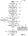
- an exemplary method for encoding a frame with a redundant slice is indicated generally by the reference numeral 400.
- the method 400 includes a start block 405 that passes control to a function block 410.
- the function block 410 inputs video frame n (non-IDR, reference frame), and passes control to a function block 415.
- the function block 415 codes the primary slice, and passes control to a function block 420.
- the function block 420 performs error concealment for frame n, and passes control to a function block 425.
- the function block 425 performs distortion area selection to form the content of the redundant slice, and passes control to a loop limit block 430.
- the loop limit block 430 begins a loop for each macroblock in the redundant slice, and passes control to a decision block 440.
- the decision block 440 determines whether or not this macroblock is selected for copying into the redundant slice. If so, then control is passed to a function block 445. Otherwise, control is passed to a function block 460.
- the function block 445 disables only SKIP mode, and passes control to a function block 450.
- the function block 450 performs regular encoding of the macroblock, and passes control to a loop limit block 455.
- the loop limit block 455 ends the loop for each macroblock in the redundant slice, and passes control to an end block 499.
- the function block 460 disables all macroblock coding modes except SKIP mode, and passes control to the function block 450.
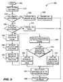
- an exemplary method for decoding a frame with a redundant slice is indicated generally by the reference numeral 500.
- the method 500 includes a start block 505 that passes control to a function block 510.
- the function block 510 inputs a slice(s) for frame n, and passes control to a decision block 515.
- the decision block 515 determines whether or not the primary slice is present. If so, then control is passed to a function block 520. Otherwise, control is passed to a decision block 530.
- the function block 520 decodes the primary slice, and passes control to a function block 525.
- the function block 525 discards the redundant slice, and passes control to an end block 599.
- the end block 599 ends the decoding of the frame.
- the decision block 530 determines whether or not the redundant slice is present. If so, the control is passed to a function block 535. Otherwise, control is passed to a function block 575.
- the function block 535 obtains the concealed frame, and passes control to a function block 540.
- the function block 540 initializes the skip_mode_map structure, and passes control to a function block 545.
- the function block 545 decodes the redundant slice, fills in the slip_mode_map structure, and passes control to a loop limit block 550.
- the loop limit block 550 begins a loop over each macroblock in the reconstructed frame, and passes control to a decision block 555.
- the decision block 555 determines whether or not the macroblock is in SKIP mode according to skip_mode_map. If so, then control is passed to a function block 560. Otherwise, control is passed to a function block 570.
- the function block 560 copies the macroblock from the concealed frame, and passes control to a loop limit block 565.
- the loop limit block 565 ends the loop for each macroblock in the reconstructed frame, and passes control to an end block 599.
- the end block 599 ends the decoding of the frame.
- the function block 575 conceals the frame, and passes control to the end block 599.
- the function block 570 copies the macroblock from the decoded redundant slice, and passes control to the loop limit block 565.
- one advantage/feature is an apparatus having an encoder for encoding a redundant coded picture corresponding to a source picture by selecting individual blocks in the source picture for inclusion into the redundant coded picture.
- Another advantage/feature is the apparatus having the encoder as described above, wherein the encoder selects the individual blocks using a decoder error concealment operation that considers when a primary picture corresponding to the redundant coded picture is unavailable at a decoder.
- Yet another advantage/feature is the apparatus having the encoder as described above, wherein the encoder uses SKIP mode to indicate that a particular one of the individual blocks is not coded in the redundant coded picture.
- Still another advantage/feature is the apparatus having the encoder as described above, wherein the encoder is configured to ensure that the SKIP mode is prohibited from use for any of the individual blocks coded in the redundant coded picture. Moreover, another advantage/feature is the apparatus having the encoder as described above, wherein the encoder selects the individual blocks based on a distortion measure. Further, another advantage/feature is the apparatus having the encoder that selects the individual blocks based on a distortion measure as described above, wherein the distortion measure is calculated using pixel absolute difference.
- another advantage/feature is the apparatus having the encoder as described above, wherein the encoder selects the individual blocks by respectively classifying each of pixels in a distortion image as distorted when a respective distortion measure between a particular one of the pixels in the distortion image and a corresponding pixel in the source image is greater than a first threshold and respectively selecting any of the individual blocks having a respective number of distorted pixels greater than a second threshold.
- another advantage/feature is the apparatus having the encoder that selects the individual blocks using the pixel classification and the first threshold as described above, wherein the distortion image represents a difference between an encoder-reconstructed picture and a decoder reconstructed image formed using a decoder error concealment operation.
- another advantage/feature is the apparatus having the encoder that selects the individual blocks using the pixel classification and the first threshold as described above, wherein the distortion image is calculated using a decoder concealment operation applied to an encoder-reconstructed picture corresponding to the source picture and another encoder-reconstructed picture corresponding to another source picture immediately preceding the source image.
- another advantage/feature is the apparatus having the encoder that selects the individual blocks using the pixel classification and the first threshold as described above, wherein any of the individual blocks having the respective number of distorted pixels greater than the second threshold are classified as distorted.
- another advantage/feature is the apparatus having the encoder as described above, wherein each of the individual blocks have a block size of 16x16.
- the various aspects, implementations, and features in this disclosure may be implemented in one or more of a variety of manners, even if described above using only one manner.
- the various aspects, implementations, and features may be implemented using, for example, one or more of a method, an apparatus, an apparatus for performing a method, a program or other set of instructions, an apparatus that includes a program or a set of instructions, and a computer readable medium.
- the computer readable medium may include, for example, instructions, software, images, and other data.
- implementations may include one or more devices configured to perform one or more processes.
- a device may include, for example, discrete or integrated hardware, firmware, and software.
- Such a device may include, for example, a processor, which refers to processing devices in general, including, for example, a microprocessor, an integrated circuit, or a programmable logic device.
- One implementation includes, therefore, an encoder and a decoder running software for implementing one or more of the described algorithms.
- a device also may include one or more computer readable media having instructions for carrying out one or more processes.
- the computer readable medium may include, for example, a storage device such as, for example, a hard disk, a compact diskette, a random access memory ("RAM"), or a read-only memory ("ROM").
- a computer readable medium also may include, for example, formatted electromagnetic waves encoding or transmitting instructions. Instructions may be, for example, in hardware, firmware, software, or in an electromagnetic wave. Instructions may be found in, for example, an operating system, a separate application, or a combination of the two.
- a processor may be characterized therefore, as, for example, both a device configured to carry out a process and a device including computer readable media having instructions for carrying out a process.
- the teachings of the present invention are implemented as a combination of hardware and software.
- the software may be implemented as an application program tangibly embodied on a program storage unit.
- the application program may be uploaded to, and executed by, a machine comprising any suitable architecture.
- the machine is implemented on a computer platform having hardware such as one or more central processing units (“CPU"), a random access memory (“RAM”), and input/output ("I/O") interfaces.
- CPU central processing units
- RAM random access memory
- I/O input/output
- the computer platform may also include an operating system and microinstruction code.
- the various processes and functions described herein may be either part of the microinstruction code or part of the application program, or any combination thereof, which may be executed by a CPU.
- various other peripheral units may be connected to the computer platform such as an additional data storage unit and a printing unit.
Landscapes
- Engineering & Computer Science (AREA)
- Multimedia (AREA)
- Signal Processing (AREA)
- Compression Or Coding Systems Of Tv Signals (AREA)
Claims (15)
- Vorrichtung, die umfasst:einen Codierer (100) zum Codieren von Bilddaten zum Erzeugen eines redundanten codierten Bilds, das einem codierten Quellbild entspricht, wobeidie Auswahl einzelner Makroblöcke in dem Quellbild zur Aufnahme in das redundante codierte Bild das Ergebnis einer Berechnung eines Verzerrungsbilds verwendet, das erzeugt wird, falls das codierte Quellbild verlorengeht und durch einen Fehlerverdeckungsbetrieb verdeckt wird, undder Codierer eine SKIP-Betriebsart-Codierung verwendet, wodurch für einen Decodierer angegeben wird, welche bestimmten Makroblöcke in das redundante codierte Bild aufgenommen worden sind.
- Verfahren, das umfasst:Codieren von Bilddaten zum Erzeugen eines redundanten codierten Bilds, das einem codierten Quellbild entspricht, durchAuswählen einzelner Makroblöcke in dem Quellbild zur Aufnahme in das redundante codierte Bild unter Verwendung des Ergebnisses einer Berechnung eines Verzerrungsbilds, das erzeugt wird, falls das codierte Quellbild verlorengeht und durch einen Fehlerverdeckungsbetrieb verdeckt wird, undSenden von Informationen von dem Codierer unter Verwendung einer SKIP-Betriebsart-Codierung und dadurch Angeben, welche bestimmten Blöcke in das redundante codierte Bild aufgenommen worden sind.
- Vorrichtung nach Anspruch 1 oder Verfahren nach Anspruch 2, wobei der Codierer (100) eine SKIP-Betriebsart verwendet, um anzugeben, dass ein Bestimmter der einzelnen Makroblöcke nicht in die Bilddaten aufgenommen worden ist.
- Vorrichtung nach Anspruch 1 oder Verfahren nach Anspruch 2, wobei der Codierer (100) dafür konfiguriert ist sicherzustellen, dass die SKIP-Betriebsart vor der Verwendung für irgendwelche der einzelnen Makroblöcke, die in die Bilddaten aufgenommen worden sind, geschützt ist.
- Vorrichtung nach Anspruch 1 oder Verfahren nach Anspruch 2, wobei der Codierer (100) die einzelnen Makroblöcke durch jeweiliges Klassifizieren jedes der Pixel in einem Verzerrungsbild als verzerrt, wenn ein jeweiliges Verzerrungsmaß zwischen einem bestimmten der Pixel in dem Verzerrungsbild und einem entsprechenden Pixel in dem Quellbild größer als ein erster Schwellenwert ist, und jeweiliges Auswählen irgendeines der einzelnen Makroblöcke mit einer jeweiligen Anzahl verzerrter Pixel größer als ein zweiter Schwellenwert auswählt.
- Vorrichtung oder Verfahren nach Anspruch 5, wobei das Verzerrungsbild eine unter Verwendung eines Decodierer-Fehlerverdeckungsbetriebs erzeugte Differenz zwischen einem durch den Codierer rekonstruierten Bild und einem durch den Decodierer rekonstruierten Bild repräsentiert.
- Vorrichtung oder Verfahren nach Anspruch 5, wobei das Verzerrungsbild unter Verwendung eines Decodiererverdeckungsbetriebs berechnet wird, der auf ein vom Codierer rekonstruiertes Bild, das dem Quellbild entspricht, und auf ein weiteres vom Codierer rekonstruiertes Bild, das einem weiteren Quellbild entspricht, das dem Quellbild unmittelbar vorhergeht, angewendet wird.
- Vorrichtung oder Verfahren nach Anspruch 5, wobei irgendwelche der einzelnen Makroblöcke, die die jeweilige Anzahl gestörter Pixel größer als der zweite Schwellenwert aufweisen, als gestört klassifiziert werden.
- Vorrichtung nach Anspruch 1 oder Verfahren nach Anspruch 2, wobei jeder der einzelnen Makroblöcke eine Größe von 16 × 16 aufweist.
- Vorrichtung, die umfasst:einen Decodierer (200) zum Bilden eines rekonstruierten Bilds, wenn ein primäres Bild nicht verfügbar ist, durch Decodieren eines redundanten codierten Bilds, das dem primären codierten Bild entspricht, wobei das redundante codierte Bild die SKIP-Betriebsart-Codierung verwendet, um anzugeben, welche bestimmten Makroblöcke in die Bilddaten aufgenommen worden sind, und durch Kombinieren des decodierten redundanten codierten Bild mit einem verdeckten Bild auf der Grundlage mindestens eines zuvor codierten primären Bilds.
- Verfahren, das umfasst:Decodieren zum Bilden eines rekonstruierten Bilds, wenn ein primäres Bild nicht verfügbar ist, durch Decodieren eines redundanten codierten Bilds, das dem primären codierten Bild entspricht, wobei das redundante codierte Bild die SKIP-Betriebsart-Codierung verwendet, um anzugeben, welche bestimmten Makroblöcke in die Bilddaten aufgenommen worden sind, und durch Kombinieren des decodierten redundanten codierten Bilds mit einem verdeckten Bild auf der Grundlage mindestens eines zuvor codierten primären Bilds.
- Vorrichtung nach Anspruch 10 oder Verfahren nach Anspruch 11, wobei das verdeckte Bild zum Decodieren eines einzelnen Blocks verwendet wird, wenn der einzelne Block unter Verwendung der SKIP-Betriebsart codiert wird, und wobei sie das redundante codierte Bild zum Decodieren des einzelnen Blocks verwendet, wenn der einzelne Makroblock unter Verwendung einer Nicht-SKIP-Betriebsart codiert wird.
- Vorrichtung nach Anspruch 10 oder Verfahren nach Anspruch 11, wobei das verdeckte Bild unter Verwendung einer Einzelbildkopie erzeugt wird.
- Vorrichtung nach Anspruch 10 oder Verfahren nach Anspruch 11, wobei das verdeckte Bild unter Verwendung einer Bewegungskopie erzeugt wird.
- Vorrichtung nach Anspruch 10 oder Verfahren nach Anspruch 11, wobei jeder der einzelnen Makroblöcke eine Größe von 16 × 16 aufweist.
Applications Claiming Priority (2)
| Application Number | Priority Date | Filing Date | Title |
|---|---|---|---|
| US79353906P | 2006-04-20 | 2006-04-20 | |
| PCT/US2007/005115 WO2007126517A2 (en) | 2006-04-20 | 2007-02-27 | Method and apparatus for redundant video coding |
Publications (2)
| Publication Number | Publication Date |
|---|---|
| EP2008468A2 EP2008468A2 (de) | 2008-12-31 |
| EP2008468B1 true EP2008468B1 (de) | 2012-06-13 |
Family
ID=38543698
Family Applications (1)
| Application Number | Title | Priority Date | Filing Date |
|---|---|---|---|
| EP07751848A Active EP2008468B1 (de) | 2006-04-20 | 2007-02-27 | Verfahren und vorrichtung zur redundanten videocodierung |
Country Status (7)
| Country | Link |
|---|---|
| US (1) | US9300956B2 (de) |
| EP (1) | EP2008468B1 (de) |
| JP (2) | JP5313880B2 (de) |
| KR (1) | KR101378079B1 (de) |
| CN (1) | CN101427582B (de) |
| BR (1) | BRPI0710093A2 (de) |
| WO (1) | WO2007126517A2 (de) |
Families Citing this family (15)
| Publication number | Priority date | Publication date | Assignee | Title |
|---|---|---|---|---|
| US8824553B2 (en) | 2003-05-12 | 2014-09-02 | Google Inc. | Video compression method |
| KR101378079B1 (ko) | 2006-04-20 | 2014-03-28 | 톰슨 라이센싱 | 중복 비디오 코딩을 위한 방법 및 장치 |
| US9872045B2 (en) | 2006-10-16 | 2018-01-16 | Conversant Wireless Licensing S.A R.L. | Method, electronic device, system, computer program product and circuit assembly for reducing error in video coding |
| FR2910211A1 (fr) * | 2006-12-19 | 2008-06-20 | Canon Kk | Procedes et dispositifs pour re-synchroniser un flux video endommage. |
| CN101321284B (zh) * | 2007-06-10 | 2012-01-04 | 华为技术有限公司 | 一种编解码方法、设备及系统 |
| US8249142B2 (en) * | 2008-04-24 | 2012-08-21 | Motorola Mobility Llc | Method and apparatus for encoding and decoding video using redundant encoding and decoding techniques |
| EP2302845B1 (de) | 2009-09-23 | 2012-06-20 | Google, Inc. | Verfahren und Vorrichtung zur Bestimmung eines Jitterpuffer-Niveaus |
| CN102823248B (zh) | 2010-04-08 | 2015-06-24 | 株式会社东芝 | 图像编码方法以及图像编码装置 |
| US8630412B2 (en) | 2010-08-25 | 2014-01-14 | Motorola Mobility Llc | Transport of partially encrypted media |
| US8477050B1 (en) | 2010-09-16 | 2013-07-02 | Google Inc. | Apparatus and method for encoding using signal fragments for redundant transmission of data |
| US8838680B1 (en) | 2011-02-08 | 2014-09-16 | Google Inc. | Buffer objects for web-based configurable pipeline media processing |
| US20120320993A1 (en) * | 2011-06-14 | 2012-12-20 | Google Inc. | Apparatus and method for mitigating the effects of packet loss on digital video streams |
| US8819525B1 (en) | 2012-06-14 | 2014-08-26 | Google Inc. | Error concealment guided robustness |
| EP2838268B1 (de) * | 2013-07-31 | 2019-02-20 | Axis AB | Verfahren, Vorrichtung und System zur Herstellung einer zusammengeführten digitalen Videosequenz |
| CN104754341B (zh) * | 2013-12-31 | 2019-02-26 | 华为技术有限公司 | 一种视频数据编码、解码的方法和装置 |
Family Cites Families (11)
| Publication number | Priority date | Publication date | Assignee | Title |
|---|---|---|---|---|
| US6480542B1 (en) * | 1994-08-24 | 2002-11-12 | Siemens Aktiengesellschaft | Method for decoding compressed video data with a reduced memory requirement |
| US5724369A (en) * | 1995-10-26 | 1998-03-03 | Motorola Inc. | Method and device for concealment and containment of errors in a macroblock-based video codec |
| CN1134174C (zh) * | 2001-06-08 | 2004-01-07 | 清华大学 | 地面数字电视广播中的视频差错隐藏方法 |
| US6910175B2 (en) * | 2001-09-14 | 2005-06-21 | Koninklijke Philips Electronics N.V. | Encoder redundancy selection system and method |
| US6697290B2 (en) | 2001-12-12 | 2004-02-24 | Agilent Technologies, Inc. | Apparatus for random access memory array self-repair |
| US7012963B2 (en) | 2002-11-14 | 2006-03-14 | Opentv, Inc. | Positioning of images in a data stream |
| KR20050105271A (ko) * | 2003-03-03 | 2005-11-03 | 코닌클리케 필립스 일렉트로닉스 엔.브이. | 비디오 인코딩 |
| US7000155B2 (en) | 2003-04-21 | 2006-02-14 | International Business Machines Corporation | Redundancy register architecture for soft-error tolerance and methods of making the same |
| US20040218669A1 (en) * | 2003-04-30 | 2004-11-04 | Nokia Corporation | Picture coding method |
| CA2573990A1 (en) * | 2004-07-15 | 2006-02-23 | Qualcomm Incorporated | H.264 spatial error concealment based on the intra-prediction direction |
| KR101378079B1 (ko) * | 2006-04-20 | 2014-03-28 | 톰슨 라이센싱 | 중복 비디오 코딩을 위한 방법 및 장치 |
-
2007
- 2007-02-27 KR KR1020087024204A patent/KR101378079B1/ko active IP Right Grant
- 2007-02-27 CN CN200780014001XA patent/CN101427582B/zh active Active
- 2007-02-27 JP JP2009506490A patent/JP5313880B2/ja active Active
- 2007-02-27 BR BRPI0710093-0A patent/BRPI0710093A2/pt not_active IP Right Cessation
- 2007-02-27 US US12/225,909 patent/US9300956B2/en active Active
- 2007-02-27 WO PCT/US2007/005115 patent/WO2007126517A2/en active Application Filing
- 2007-02-27 EP EP07751848A patent/EP2008468B1/de active Active
-
2013
- 2013-04-19 JP JP2013088541A patent/JP5722943B2/ja not_active Expired - Fee Related
Also Published As
| Publication number | Publication date |
|---|---|
| EP2008468A2 (de) | 2008-12-31 |
| JP5722943B2 (ja) | 2015-05-27 |
| KR101378079B1 (ko) | 2014-03-28 |
| CN101427582A (zh) | 2009-05-06 |
| BRPI0710093A2 (pt) | 2011-08-02 |
| US9300956B2 (en) | 2016-03-29 |
| JP2013176129A (ja) | 2013-09-05 |
| WO2007126517A2 (en) | 2007-11-08 |
| CN101427582B (zh) | 2013-10-23 |
| KR20090003305A (ko) | 2009-01-09 |
| WO2007126517A3 (en) | 2008-05-22 |
| US20090052543A1 (en) | 2009-02-26 |
| JP2009534922A (ja) | 2009-09-24 |
| JP5313880B2 (ja) | 2013-10-09 |
Similar Documents
| Publication | Publication Date | Title |
|---|---|---|
| EP2008468B1 (de) | Verfahren und vorrichtung zur redundanten videocodierung | |
| US9414086B2 (en) | Partial frame utilization in video codecs | |
| US8208545B2 (en) | Method and apparatus for video coding on pixel-wise prediction | |
| JP5174958B2 (ja) | ビデオのコーダとデコーダとの同時最適化のための方法およびシステム | |
| US7738716B2 (en) | Encoding and decoding apparatus and method for reducing blocking phenomenon and computer-readable recording medium storing program for executing the method | |
| EP1755346A1 (de) | Verfahren und Vorrichtung zur Videokodierung- und Dekodierung | |
| US20060188025A1 (en) | Error concealment | |
| JP2009284518A (ja) | ビデオ符号化方法 | |
| WO2007091601A1 (ja) | 符号化装置、符号化方法およびプログラム | |
| EP1496708A1 (de) | Vorrichtungen, Verfahren und Programme zur Kodierung von bewegten Bildern | |
| KR100809603B1 (ko) | 화소 단위 기반 영상 부호화 및 복호화 장치 및 방법 | |
| JP4828950B2 (ja) | 動画像復号装置 | |
| KR101583870B1 (ko) | 이미지 인코딩 시스템, 디코딩 시스템 및 그 제공방법 | |
| KR100856215B1 (ko) | 동영상 복호화시 프레임 손실의 은폐 방법 및 장치 | |
| JP2005260989A (ja) | 画像処理装置及び画像処理方法 | |
| JP2007235931A (ja) | 画像復号化方法及び画像復号化装置 | |
| KR20150096353A (ko) | 이미지 인코딩 시스템, 디코딩 시스템 및 그 제공방법 | |
| KR100312418B1 (ko) | 동영상부호화장치에서인트라모드부호화선택방법 | |
| US8358694B2 (en) | Effective error concealment in real-world transmission environment | |
| JP3756902B2 (ja) | 動画像復号化装置及び動画像復号化方法 | |
| Cheung | Error resilient support in video proxy over wireless channels | |
| KR20060043867A (ko) | 영상 신호의 인코딩 및 디코딩 방법 |
Legal Events
| Date | Code | Title | Description |
|---|---|---|---|
| PUAI | Public reference made under article 153(3) epc to a published international application that has entered the european phase |
Free format text: ORIGINAL CODE: 0009012 |
|
| 17P | Request for examination filed |
Effective date: 20081024 |
|
| AK | Designated contracting states |
Kind code of ref document: A2 Designated state(s): AT BE BG CH CY CZ DE DK EE ES FI FR GB GR HU IE IS IT LI LT LU LV MC NL PL PT RO SE SI SK TR |
|
| AX | Request for extension of the european patent |
Extension state: AL BA HR MK RS |
|
| DAX | Request for extension of the european patent (deleted) | ||
| RBV | Designated contracting states (corrected) |
Designated state(s): DE FR GB |
|
| 17Q | First examination report despatched |
Effective date: 20090511 |
|
| R17C | First examination report despatched (corrected) |
Effective date: 20090609 |
|
| RAP1 | Party data changed (applicant data changed or rights of an application transferred) |
Owner name: THOMSON LICENSING |
|
| GRAP | Despatch of communication of intention to grant a patent |
Free format text: ORIGINAL CODE: EPIDOSNIGR1 |
|
| GRAS | Grant fee paid |
Free format text: ORIGINAL CODE: EPIDOSNIGR3 |
|
| GRAA | (expected) grant |
Free format text: ORIGINAL CODE: 0009210 |
|
| AK | Designated contracting states |
Kind code of ref document: B1 Designated state(s): DE FR GB |
|
| REG | Reference to a national code |
Ref country code: GB Ref legal event code: FG4D |
|
| REG | Reference to a national code |
Ref country code: GB Ref legal event code: 746 Effective date: 20120702 |
|
| REG | Reference to a national code |
Ref country code: DE Ref legal event code: R096 Ref document number: 602007023361 Country of ref document: DE Effective date: 20120809 |
|
| REG | Reference to a national code |
Ref country code: DE Ref legal event code: R084 Ref document number: 602007023361 Country of ref document: DE Effective date: 20120616 |
|
| PLBE | No opposition filed within time limit |
Free format text: ORIGINAL CODE: 0009261 |
|
| STAA | Information on the status of an ep patent application or granted ep patent |
Free format text: STATUS: NO OPPOSITION FILED WITHIN TIME LIMIT |
|
| 26N | No opposition filed |
Effective date: 20130314 |
|
| REG | Reference to a national code |
Ref country code: DE Ref legal event code: R097 Ref document number: 602007023361 Country of ref document: DE Effective date: 20130314 |
|
| REG | Reference to a national code |
Ref country code: FR Ref legal event code: PLFP Year of fee payment: 10 |
|
| REG | Reference to a national code |
Ref country code: FR Ref legal event code: PLFP Year of fee payment: 11 |
|
| REG | Reference to a national code |
Ref country code: DE Ref legal event code: R082 Ref document number: 602007023361 Country of ref document: DE Representative=s name: DEHNS, DE Ref country code: DE Ref legal event code: R082 Ref document number: 602007023361 Country of ref document: DE Representative=s name: DEHNS PATENT AND TRADEMARK ATTORNEYS, DE Ref country code: DE Ref legal event code: R082 Ref document number: 602007023361 Country of ref document: DE Representative=s name: HOFSTETTER, SCHURACK & PARTNER PATENT- UND REC, DE |
|
| REG | Reference to a national code |
Ref country code: FR Ref legal event code: PLFP Year of fee payment: 12 |
|
| REG | Reference to a national code |
Ref country code: FR Ref legal event code: TP Owner name: THOMSON LICENSING DTV, FR Effective date: 20180830 |
|
| REG | Reference to a national code |
Ref country code: GB Ref legal event code: 732E Free format text: REGISTERED BETWEEN 20180927 AND 20181005 |
|
| REG | Reference to a national code |
Ref country code: DE Ref legal event code: R082 Ref document number: 602007023361 Country of ref document: DE Representative=s name: DEHNS, DE Ref country code: DE Ref legal event code: R081 Ref document number: 602007023361 Country of ref document: DE Owner name: INTERDIGITAL MADISON PATENT HOLDINGS, FR Free format text: FORMER OWNER: THOMSON LICENSING, ISSY-LES-MOULINEAUX, FR Ref country code: DE Ref legal event code: R082 Ref document number: 602007023361 Country of ref document: DE Representative=s name: DEHNS PATENT AND TRADEMARK ATTORNEYS, DE |
|
| PGFP | Annual fee paid to national office [announced via postgrant information from national office to epo] |
Ref country code: FR Payment date: 20230223 Year of fee payment: 17 |
|
| PGFP | Annual fee paid to national office [announced via postgrant information from national office to epo] |
Ref country code: GB Payment date: 20230214 Year of fee payment: 17 Ref country code: DE Payment date: 20230227 Year of fee payment: 17 |
|
| P01 | Opt-out of the competence of the unified patent court (upc) registered |
Effective date: 20230514 |