EP2838268B1 - Verfahren, Vorrichtung und System zur Herstellung einer zusammengeführten digitalen Videosequenz - Google Patents
Verfahren, Vorrichtung und System zur Herstellung einer zusammengeführten digitalen Videosequenz Download PDFInfo
- Publication number
- EP2838268B1 EP2838268B1 EP13178768.1A EP13178768A EP2838268B1 EP 2838268 B1 EP2838268 B1 EP 2838268B1 EP 13178768 A EP13178768 A EP 13178768A EP 2838268 B1 EP2838268 B1 EP 2838268B1
- Authority
- EP
- European Patent Office
- Prior art keywords
- video sequence
- digital video
- frame
- pixels
- block
- Prior art date
- Legal status (The legal status is an assumption and is not a legal conclusion. Google has not performed a legal analysis and makes no representation as to the accuracy of the status listed.)
- Active
Links
- 238000000034 method Methods 0.000 title claims description 38
- 238000012545 processing Methods 0.000 claims description 37
- 238000004458 analytical method Methods 0.000 claims description 19
- 238000004519 manufacturing process Methods 0.000 claims description 7
- 230000006835 compression Effects 0.000 claims description 6
- 238000007906 compression Methods 0.000 claims description 6
- 238000001914 filtration Methods 0.000 claims description 5
- 230000033001 locomotion Effects 0.000 description 34
- 238000012544 monitoring process Methods 0.000 description 15
- 238000001514 detection method Methods 0.000 description 11
- 230000005540 biological transmission Effects 0.000 description 6
- 239000013598 vector Substances 0.000 description 5
- 241000282326 Felis catus Species 0.000 description 4
- 230000002123 temporal effect Effects 0.000 description 3
- 238000000605 extraction Methods 0.000 description 2
- 238000012806 monitoring device Methods 0.000 description 2
- 230000003068 static effect Effects 0.000 description 2
- 241001465754 Metazoa Species 0.000 description 1
- 241000405217 Viola <butterfly> Species 0.000 description 1
- 230000003044 adaptive effect Effects 0.000 description 1
- 238000004891 communication Methods 0.000 description 1
- 238000010586 diagram Methods 0.000 description 1
- 238000003708 edge detection Methods 0.000 description 1
- 238000005286 illumination Methods 0.000 description 1
- 230000001788 irregular Effects 0.000 description 1
- 239000000203 mixture Substances 0.000 description 1
- 238000012986 modification Methods 0.000 description 1
- 230000004048 modification Effects 0.000 description 1
- 238000013139 quantization Methods 0.000 description 1
- 238000011084 recovery Methods 0.000 description 1
Images


Classifications
-
- H—ELECTRICITY
- H04—ELECTRIC COMMUNICATION TECHNIQUE
- H04N—PICTORIAL COMMUNICATION, e.g. TELEVISION
- H04N19/00—Methods or arrangements for coding, decoding, compressing or decompressing digital video signals
- H04N19/10—Methods or arrangements for coding, decoding, compressing or decompressing digital video signals using adaptive coding
- H04N19/169—Methods or arrangements for coding, decoding, compressing or decompressing digital video signals using adaptive coding characterised by the coding unit, i.e. the structural portion or semantic portion of the video signal being the object or the subject of the adaptive coding
- H04N19/187—Methods or arrangements for coding, decoding, compressing or decompressing digital video signals using adaptive coding characterised by the coding unit, i.e. the structural portion or semantic portion of the video signal being the object or the subject of the adaptive coding the unit being a scalable video layer
-
- H—ELECTRICITY
- H04—ELECTRIC COMMUNICATION TECHNIQUE
- H04N—PICTORIAL COMMUNICATION, e.g. TELEVISION
- H04N19/00—Methods or arrangements for coding, decoding, compressing or decompressing digital video signals
- H04N19/10—Methods or arrangements for coding, decoding, compressing or decompressing digital video signals using adaptive coding
- H04N19/169—Methods or arrangements for coding, decoding, compressing or decompressing digital video signals using adaptive coding characterised by the coding unit, i.e. the structural portion or semantic portion of the video signal being the object or the subject of the adaptive coding
- H04N19/17—Methods or arrangements for coding, decoding, compressing or decompressing digital video signals using adaptive coding characterised by the coding unit, i.e. the structural portion or semantic portion of the video signal being the object or the subject of the adaptive coding the unit being an image region, e.g. an object
- H04N19/176—Methods or arrangements for coding, decoding, compressing or decompressing digital video signals using adaptive coding characterised by the coding unit, i.e. the structural portion or semantic portion of the video signal being the object or the subject of the adaptive coding the unit being an image region, e.g. an object the region being a block, e.g. a macroblock
-
- H—ELECTRICITY
- H04—ELECTRIC COMMUNICATION TECHNIQUE
- H04N—PICTORIAL COMMUNICATION, e.g. TELEVISION
- H04N19/00—Methods or arrangements for coding, decoding, compressing or decompressing digital video signals
- H04N19/10—Methods or arrangements for coding, decoding, compressing or decompressing digital video signals using adaptive coding
- H04N19/102—Methods or arrangements for coding, decoding, compressing or decompressing digital video signals using adaptive coding characterised by the element, parameter or selection affected or controlled by the adaptive coding
- H04N19/117—Filters, e.g. for pre-processing or post-processing
-
- H—ELECTRICITY
- H04—ELECTRIC COMMUNICATION TECHNIQUE
- H04N—PICTORIAL COMMUNICATION, e.g. TELEVISION
- H04N19/00—Methods or arrangements for coding, decoding, compressing or decompressing digital video signals
- H04N19/10—Methods or arrangements for coding, decoding, compressing or decompressing digital video signals using adaptive coding
- H04N19/102—Methods or arrangements for coding, decoding, compressing or decompressing digital video signals using adaptive coding characterised by the element, parameter or selection affected or controlled by the adaptive coding
- H04N19/132—Sampling, masking or truncation of coding units, e.g. adaptive resampling, frame skipping, frame interpolation or high-frequency transform coefficient masking
-
- H—ELECTRICITY
- H04—ELECTRIC COMMUNICATION TECHNIQUE
- H04N—PICTORIAL COMMUNICATION, e.g. TELEVISION
- H04N19/00—Methods or arrangements for coding, decoding, compressing or decompressing digital video signals
- H04N19/10—Methods or arrangements for coding, decoding, compressing or decompressing digital video signals using adaptive coding
- H04N19/134—Methods or arrangements for coding, decoding, compressing or decompressing digital video signals using adaptive coding characterised by the element, parameter or criterion affecting or controlling the adaptive coding
- H04N19/167—Position within a video image, e.g. region of interest [ROI]
-
- H—ELECTRICITY
- H04—ELECTRIC COMMUNICATION TECHNIQUE
- H04N—PICTORIAL COMMUNICATION, e.g. TELEVISION
- H04N19/00—Methods or arrangements for coding, decoding, compressing or decompressing digital video signals
- H04N19/20—Methods or arrangements for coding, decoding, compressing or decompressing digital video signals using video object coding
- H04N19/29—Methods or arrangements for coding, decoding, compressing or decompressing digital video signals using video object coding involving scalability at the object level, e.g. video object layer [VOL]
-
- H—ELECTRICITY
- H04—ELECTRIC COMMUNICATION TECHNIQUE
- H04N—PICTORIAL COMMUNICATION, e.g. TELEVISION
- H04N19/00—Methods or arrangements for coding, decoding, compressing or decompressing digital video signals
- H04N19/50—Methods or arrangements for coding, decoding, compressing or decompressing digital video signals using predictive coding
- H04N19/503—Methods or arrangements for coding, decoding, compressing or decompressing digital video signals using predictive coding involving temporal prediction
-
- H—ELECTRICITY
- H04—ELECTRIC COMMUNICATION TECHNIQUE
- H04N—PICTORIAL COMMUNICATION, e.g. TELEVISION
- H04N19/00—Methods or arrangements for coding, decoding, compressing or decompressing digital video signals
- H04N19/50—Methods or arrangements for coding, decoding, compressing or decompressing digital video signals using predictive coding
- H04N19/59—Methods or arrangements for coding, decoding, compressing or decompressing digital video signals using predictive coding involving spatial sub-sampling or interpolation, e.g. alteration of picture size or resolution
-
- H—ELECTRICITY
- H04—ELECTRIC COMMUNICATION TECHNIQUE
- H04N—PICTORIAL COMMUNICATION, e.g. TELEVISION
- H04N19/00—Methods or arrangements for coding, decoding, compressing or decompressing digital video signals
- H04N19/60—Methods or arrangements for coding, decoding, compressing or decompressing digital video signals using transform coding
- H04N19/61—Methods or arrangements for coding, decoding, compressing or decompressing digital video signals using transform coding in combination with predictive coding
-
- H—ELECTRICITY
- H04—ELECTRIC COMMUNICATION TECHNIQUE
- H04N—PICTORIAL COMMUNICATION, e.g. TELEVISION
- H04N19/00—Methods or arrangements for coding, decoding, compressing or decompressing digital video signals
- H04N19/70—Methods or arrangements for coding, decoding, compressing or decompressing digital video signals characterised by syntax aspects related to video coding, e.g. related to compression standards
Definitions
- the present invention relates to a method, a video processing device and a system for producing a frame of a merged digital video sequence.
- Monitoring devices especially video recording devices are today widely used for monitoring of different premises, e.g. houses, road strips, metro stations or production plants. By recording a monitoring video sequence, information pertaining to an event, being e.g. a crime, an accident or a production miss failure, may be recapitulated by play back of the monitoring video sequence.
- a video recording device is a digital monitoring camera being arranged to capture digital video sequences and to send the digital video sequences over a network e.g. the internet.
- a digital monitoring camera is typically set up to operate according to the following.
- the camera's components comprising a lens and an image sensor
- capture images which can be described as light of different wavelengths, and transforms them into electrical signals. These signals are then converted from analog to digital format. Thereafter the digital format signals are being subjected to digital image processing before being sent over the network.
- a trend of today is that the cameras are equipped with better and better image sensors having higher and higher image resolution. This results in that the amount of monitoring digital video sequence data to be sent over the network is increasing. Moreover, also the amount of monitoring digital video sequence data to be stored is increasing. Hence, the bit rate of the monitoring digital video sequence data is increasing. In order to reduce the bit rate of the monitoring digital video sequence data the monitoring digital video sequence data is typically compressed using video coding techniques such as video coding standards of the ISO/MPEG or ITU-H.26X families.
- the INTRA-mode In modern digital video coding systems, two main modes are used to compress a video frame of a sequence of video frames: the INTRA-mode and the INTER-mode.
- the INTRA-mode the luminance and chrominance channels are encoded by exploiting the spatial redundancy of the pixels in a given channel of a single frame via prediction, transform and entropy coding.
- the INTER-mode exploiting the temporal redundancy between separate frames, relies on a motion-compensation prediction technique that predicts parts of a frame from one (or more) previously decoded frame(s) by encoding the motion in pixels from one frame to the other for selected blocks.
- the luminance and chrominance channels does not have any motion predictions.
- a motion detection algorithm is typically used to detect motion between two frames when encoding using the INTER mode.
- An image capturing module is used for capturing a scene of an area to be displayed and outputting image data.
- An image processor converts the image data according to a first and a second cutting areas and a first and a second shrink ratio values, and outputs a first and a second sub-images.
- the first cutting area includes the second cutting area, and the first shrink ratio value is greater than the second shrink ratio value.
- An image encoder encodes the first and the second sub-images according to first and second encoding information, and outputs a first and a second digital video sequences.
- a network transmission module is used for transmitting the first and the second digital video sequences to a receiver. At the receiver the two digital video sequences are decoded and reconstructed into the original image data.
- the method according to US 8208555 provide reduced bit rate of the image data both during transmission of the image data from the sending device to the receiver and during storing of the image data in the form of the two image streams.
- a drawback with this method of reducing the bit rate is that in order to play back the captured scene comparably large processing power as compared with only decoding a single encoded digital video sequence is need to both to decode the two digital video sequences and to reconstruct the image data from the decoded two digital video sequences.
- a monitoring system comprising an image processing system capable of keeping high-quality moving images of a person, a moving article and other characteristic subject to be monitored is disclosed. Additionally, the image processing system is capable of reducing data amount of the moving images.
- a sequence of moving images is captured and compressed using an image capturing apparatus.
- An image processing apparatus decodes the compressed captured moving images.
- the image processing apparatus is also arranged to detect a plurality of characteristic regions (ROIs) in the decoded moving images.
- the characteristic regions may contain different types of characters including a person, a moving article, etc. from this characteristic region moving images are generated. Hence, the ROIs are cut out from the moving images for generating the characteristic region moving images.
- the image processing apparatus also generates a background region moving image that is a moving image of a background region of the captured moving image excluding the characteristic regions.
- the generated characteristic region moving images and the background region moving image are thereafter compressed and scaled individually.
- the compressed and scaled images are thereafter merged into a merged frame.
- the apparatus includes an encoder for encoding a redundant coded picture corresponding to a source picture by selecting individual blocks in the source picture for inclusion into the redundant coded picture.
- an objective of the present invention is to enable reduction of bit rate of a digital video sequence and at the same time provide for checking the reliability of the encoding in the video recordings.
- a method for producing a frame of a merged digital video sequence is provided. The method comprises the features of claim 1.
- first and a second digital video sequences are spatially and temporally similar.
- the wording frame should be construed as one of the many still (or nearly so) images which compose the complete video sequence.
- the wording pixel should be construed as the smallest addressable element in a digital image.
- pixel density should be construed as the number of pixels of an image depicting a specific scene.
- the wording block should be construed as a group of pixels. Typical block sizes are 4x4, 8x8 or 16x16 pixels. However, in connection with the present invention also other block sizes may be used.
- the wording skip block should be construed as a block coded without sending residual error or motion vectors.
- the encoder will only record that it is a skip block.
- the decoder will deduce the motion vector of the skip block from other blocks already decoded.
- the merged digital video sequence it is safeguarded that no information of relevance is missed since the skip blocks of the first digital video sequence are replaced with image information from the second digital video sequence. Moreover, at the same time, high level of detail is maintained for the areas of the scene considered to be of relevance in the merged digital video sequence. This since, the areas of the scene considered to be of relevance are fetched from the first digital video sequence having a high level of detail due to its high resolution. Typically, areas of the scene considered to be of relevance are areas containing motion, a specific type of object, e.g. a face, a car, etc, or other information being considered relevant for the end viewer of the image. Furthermore, the merged digital video sequence is having a relatively low bit rate.
- the method may further comprise filtering, using a filter, the scaled frame of the second digital video sequence.
- filtering the scaled frame of the second digital video sequence edges from the scaling may be reduced and/or smoothen helping in producing a frame of the merged digital video sequence being better looking.
- the frame of the second digital video sequence may be encoded using a video compression algorithm, wherein the method further comprises decoding, using the decoder, the frame of the second digital video sequence.
- the bit rate of the second digital video sequence may be reduced.
- the frame of the first digital video sequence may be an INTER-frame.
- the video compression algorithm may be ITU-H.26X, ISO-MPEG, WMV, On2 or WebM compliant.
- the method may further comprise storing the frame of the merged digital video sequence in a memory.
- the merged digital video sequence may be later used for analysis, viewing, etc.
- the method may further comprise play back of the frame of the merged video sequence.
- a computer-readable recording medium having recorded thereon a program for implementing the above method when executed on a device having processing capabilities is provided.
- a video processing device arranged to execute the program recorded on the above computer-readable recording is provided.
- the video processing device may further comprise an analysis unit arranged to analyze frames of the first digital video sequence to identify pixel blocks considered to be of relevance.
- the video processing device may further comprise a mask generator arranged to output a mask indicating pixel blocks of relevance in the frames of the first digital video sequence.
- the video processing device may further comprise an encoding unit arranged to encode the frames of the first digital video sequence using the mask indicating pixel blocks of relevance into frames in an encoded version of the first video sequence, wherein the pixel blocks being masked out as not being of relevance are encoded using skip blocks.
- the video processing device may further comprise an image sensor arranged to capture a video sequence of a scene; and an image processor arranged to process the video sequence of the scene captured by the image sensor into the first and the second digital video sequence depicting the same scene.
- a system for producing a frame of a merged digital video sequence comprises the features of claim 10.
- a frame to be encoded is partitioned into minimum coding units (block, macro blocks etc) which is being compressed and encoded individually.
- minimum coding units block, macro blocks etc
- each of the blocks are assigned one or several motion vectors.
- a prediction of the frame is constructed by displacing pixel blocks from past and/or future frame(s) according to the set of motion vectors.
- the difference, called the residual signal, between the frame to be encoded and its motion-compensated prediction is entropy encoded in a similar way to the INTRA-mode by transform coding.
- a skip block is coded without sending residual error or motion vectors.
- the encoder will only record that it is a skip block.
- the decoder will deduce the image information of a skip block from other blocks already decoded.
- the image information of a skip block is preferably deduced from a block of the same frame or a block in a preceding frame of the digital video data.
- Video frames being encoded according to the INTRA-mode, without any reference to any past or future frame, are called I-frames.
- Video frames being encoded according to the INTER-mode are themselves either mono-directionally predicted frames, called P-frames and encoded with reference to a past or future frame which is an INTRA- or INTER-frame, or bi-directionally predicted frames, called B-frames and encoded with reference to two or more past or future reference frames.
- P-frames and B frames may include I-blocks which encodes new data not found anywhere in earlier frames, but usually they are rare.
- INTRA-frames comprise either scene change frames, placed at the beginning of a new group of frames corresponding to a scene change, where no temporal redundancy is available, or refresh frames, placed in other locations where some temporal redundancy is available.
- I-frames are usually inserted at regular or irregular interval to have refresh-point for new stream encoders or as a recovery point for transmission errors.
- the present invention addresses the problem of reducing the bit rate of monitoring video data captured by a monitoring device such as a networked digital video camera and at the same time provide for checking the reliability of the encoding in the video recordings. This is achieved by merging a first and a second digital video sequence depicting the same scene into a merged digital video sequence as will be discussed in more detail below.
- Figure 1 illustrates a digital network camera 110 arranged to provide the first and the second digital video sequences depicting the same scene.
- the digital network camera 110 is arranged to capture and process (and possibly also store) video data.
- the digital network camera 110 comprises a housing 112, a lens 114, an image sensor 116, an image processing unit 118, an analysis unit 120 comprising a mask generator 121, an encoding unit 122, a memory 124, a CPU 126 and an Ethernet interface 128. Any one of the image processing unit 118, the analysis unit 120 and/or encoding unit 122 may be implemented as hardware and/or software.
- the digital network camera 110 is arranged to be connected to a digital network such as the Internet or a Local Area Network (LAN) via the Ethernet interface 128.
- the connection to the digital network may be wired or wireless.
- the Ethernet interface 128 may be a network port adapted to 10/100/1000 Mbps data traffic, such as an Ethernet port, a modular port being arranged to receive a modular connector, e.g. a RJ45 connector.
- a RJ45 connector port is arranged to receive a network cable, such as a twisted pair cable (e.g. of cat 5, cat 5e or cat 6).
- the I/O means of the network port may be a wireless I/O means using mobile internet communication standards (i.e. 1G, 2G, 2.5G, 2.75G, 3G, 3.5G, 3.75G, 3.9G, 4G) or using WiFi.
- the camera components, i.e. the lens 114 and the image sensor 116, of the digital network camera 110 is arranged to capture raw images wherein each raw image can be described as light of different wavelengths and originating from different objects and parts of objects. These raw images are then converted from analog to digital format and transferred into the image processing unit 118.
- the image processing unit 118 is arranged to process the same raw images into at least two digital video sequences.
- the camera may comprise two sets of separate lenses and image sensors (not shown), wherein each set is arranged to generate separate raw images monitoring the same scene.
- the separate raw images are further processed by the image processing unit into at least two digital video sequences.
- the camera may comprise one lens, a beam splitter and two image sensors (not shown), wherein the beam splitter is arranged to separately image the same scene on two different image sensors generating separate raw images.
- the separate raw images are further processed by the image processing unit into at least two digital video sequences.
- the camera comprises two image processing units (not shown).
- a first image processing unit is arranged to provide a first digital video sequence and a second image processing unit is arranged to provide a second digital video sequence.
- the image processing unit 118 is arranged to provide a first and a second digital video sequence depicting the same scene, i.e. the first and the second digital video sequences are spatially and temporally similar.
- the first and second video sequence may have different frame rates.
- a time stamp or a frame number is used to synchronize two video sequences having different frame rates.
- the frame of one of the video sequences is a fraction of the frame rate of another of the video sequences, e.g. having the ratio 1:2.
- the second digital video sequence is recorded in parallel with the first digital video sequence.
- the image processing unit 118 is arranged to produce the first digital video sequence having a higher pixel density than the second digital video sequence.
- the bit rate of the second digital video sequence is hence much lower than the bit rate of the first digital video sequence.
- the image processing unit 118 is arranged to provide the first digital video sequence having substantially the same pixel density as the image sensor 16 and the second digital video sequence having a pixel density being a fraction of the pixel density of the image sensor 116.
- the pixel density of the second digital video sequence may be divided by four in each direction.
- the image sensor 116 is arranged to capture raw images and the image processing unit 118 is arranged to process the raw images to obtain two corresponding image sequences; a first image sequence with a first pixel density and a second image sequence with a second pixel density, the first digital video sequence having a higher pixel density than the second digital video sequence.
- the analysis unit 120 is arranged to analyze frames of the first digital video sequence to identify pixel blocks considered to be of relevance.
- pixel blocks considered to be of relevance are pixel blocks contain motion, a specific type of object, e.g. a face, a car, etc, or other information being considered relevant for the end viewer of the image.
- the analysis unit 120 further comprises a mask generator 121 being arranged to output a mask, e.g. a binary mask, indicating pixel blocks of relevance. It should be noted that the mask may be different for different images of the first digital video sequence.
- the analysis unit may also use information from the second digital video sequence to analyze the image using a pyramid based algorithm where a low resolution version is used to speed up the analysis algorithm.
- the encoding unit 122 is arranged to encode digital video sequences using video coding techniques such as video coding standards of the ISO/MPEG or ITU-H.26X families.
- the encoding unit 122 is arranged to encode the frames of the first digital video sequence using the mask indicating pixel blocks of relevance into frames in an encoded version of the first video sequence.
- the pixel blocks being masked out as not being of relevance are encoded using skip blocks.
- the first digital video sequence is achieved by processing the images in the original digital video sequence using different filters and algorithms to find what is of relevance for the user and hence should be encoded in the first video sequence.
- the different filters or algorithms are all based on detecting motion but is of different complexity. The user may configure what is considered to be relevant in the scene.
- the encoding unit 122 is arranged to be set in different encoding modes depending on the filter or algorithm used and/or on settings made by the user.
- the encoding unit 122 may be set such that faces but not cats are encoded in the first video sequence.
- the use of skip block is controlled by a video motion detection algorithm and/or a filter.
- the video motion detection algorithm is preferably based on spatio-temporal video analysis. Some examples of video motion detection algorithms and filters possible to use are: An algorithm based on "change detection". According to this algorithm an image is compared with a previous image pixel-by-pixel in order to find pixels changing between the image and the previous image.
- the detected motion is analyzed to detect moving objects which are tracked so that objects that have been in motion but are temporarily standing still is detected.
- the objects may e.g. be analyzed and classified as for example "human”, “vehicle”, “car”, “animal”, “face” etc.
- the method of Viola and Jones described in US 7,099,510 may be used.
- the video motion detection algorithm used is arranged to separate true motion from light changes as well as global changes due to camera vibrations, atmospheric movement due to for example heat and swaying tree leaves, bushes etc.
- the video motion detection algorithm is set to only detect motion above a certain level it is most likely that areas within the scene with motion below the set level of motion will not be updated and freezes in the first digital video sequence. Accordingly, areas not recognized as areas with true motion, being an example of areas not of relevance, are updated with a lower refresh rate (skip blocks are frequently used for coding the blocks of these areas) than areas recognized as areas with true motion. Areas recognized as areas with true motion are encoded without using skip blocks (hence at full frame rate and quality).
- I-frames are inserted to ease later video search and/or to update the background model of the scene that may be used for segmenting the image in a background, typically the static part of the scene, and a foreground depicting the motion in the scene.
- Adaptive I-frames may also be inserted when new motion is detected e.g. new moving objects enters the scene.
- the encoding unit 122 is further arranged to encode the second digital video sequence into an encoded version of the second video sequence.
- the second digital video sequence is preferably encoded without using the mask for identifying areas of relevance, i.e. without using more skip blocks than normal.
- the analysis unit 120 is arranged to analyze images of the second digital video sequence to identify pixel blocks considered to be of relevance and to output a mask, e.g. a binary mask, indicating pixel blocks of relevance. However, if so, a considerable higher threshold for what is not considered to be relevant for the user and hence encoded with a skip block is used when analyzing the images of the second digital video sequence.
- a basic change detection may be applied on the second digital video sequence (but no filtering for global changes etc).
- a basic change detection may be applied on the second digital video sequence (but no filtering for global changes etc).
- the encoded version of the first digital video sequence and the encoded version of the second digital video sequence may be directly transmitted over a digital network via the Ethernet interface 128.
- the encoded version of the first digital video sequence and the encoded version of the second digital video sequence may be stored in the memory 124 for later transmission, via the Ethernet interface 128 and over the digital network, of the encoded versions of the first and second video sequences.
- the memory 124 may be any kind of volatile or non-volatile memory.
- the memory 124 may comprise a plurality of memory members. At least one of the plurality of memory members may be used as a buffer memory.
- a client 210 arranged to receive and merge the encoded versions of the first and second video sequences is illustrated.
- the client may e.g. be a video management server
- the client 210 comprises an encoder unit 222, a memory 224 a CPU 226, an Ethernet interface 228, a decoder 230 comprising a skip block identifier 232, a scaler 234 comprising a filter 235, a pixel identifier 236, a block extractor 237, a merging unit 238 and a display interface 240.
- any one of the encoder unit 222, the decoder 230 comprising the skip block identifier 232, the scaler 234 comprising the filter 235, the pixel identifier 236, the block extractor 237, and/or the merging unit 238 may be implemented as hardware and/or software.
- the pixel identifier 236, the block extractor 237 and merging unit 238 could together be implemented as a multiplexer. In that case the resolution of the images in the two video sequences and the mask need to be identical. Typically the mask has a lower resolution than the video sequences (since it is dealing with blocks of pixels). A scaler could be used to scale the video sequences as well as the mask, so that a multiplexer could be used for this.
- the memory 224 of the client 210 is comparable with the memory 224 of the digital video camera 110; hence in order to avoid undue repetition reference is made to the description above.
- the encoded versions of the first and second digital video sequences depicting the same scene are received via the Ethernet interface 228.
- the Ethernet interface 228 of the client 210 is comparable with the Ethernet interface 128 of the digital video camera 110, hence in order to avoid undue repetition reference is made to the description above.
- the decoder 230 is arranged to decode the encoded versions of the first and second digital video sequences.
- the skip block identifier 232 is arranged to identify the skip blocks of the frames of the encoded version of the first digital video sequence.
- a mask e.g. binary mask
- identifying the areas of relevance in the frame of the first digital video sequence may be generated. The areas of relevance being the areas not containing skip blocks.
- the scaler 234 is arranged to upscale the frames of the decoded second digital video sequence in order to obtain up-scaled frames of the second digital video sequence having the same pixel density as the frames of the first video sequence.
- the scaler 234 is arranged to up-scale the whole frames of the second digital video sequence to fit frames of the first video sequence.
- New pixel values of the frames of the second digital video sequence are typically calculated by interpolating known pixel values. The interpolation may be performed with varying complexity, a simple method being to apply linear interpolation.
- the filter 235 is arranged to filter the up-scaled frames of the second digital video sequence to remove up-scaling artifacts.
- the filter is applied to the whole up-scaled image.
- the filter is typically used to smoothen edges from the up-scaling, by applying a mixture of edge detection, blurring and sharpening algorithms known in the art.
- the pixel identifier 236 is arranged to analyze the mask of a frame in the first digital video sequence to identify a position of a block of pixels not considered to be of relevance.
- the pixel identifier 236 is further arranged to identify a block of pixels in an up-scaled, filtered and in time corresponding frame of the second digital video sequence, wherein the identified block of pixels in the up-scaled, filtered and in time corresponding frame of the second digital video sequence corresponds to the block of pixels not considered to be of relevance identified in the frame of the first digital video sequence.
- the, in the frame of the first video sequence identified position of the block of pixels not considered to be of relevance is used to extract corresponding block of pixels from the filtered, up-scaled and in time corresponding frame of the second video sequence.
- the extraction of the block of pixels from the second digital video sequence is performed by the block extractor 237.
- the pixel identifier 236 is further arranged to analyze the mask of a frame in the first digital video sequence to identify a position of a block of pixels considered to be of relevance. Hence, the, in the frame of the first video sequence, identified position of the block of pixels considered to be of relevance is used to extract corresponding block of pixels from the first video sequence. The extraction of the block of pixels from the first digital video sequence is performed by the block extractor 237.
- the merging unit 238 is further arranged to merge the extracted block of pixels from the first digital video sequence with the extracted block of pixels from the filtered, up-scaled and in time corresponding frame of the second digital video sequence to obtain a merged frame of a merged video sequence.
- the merging unit 238 may be implemented as a multiplexer. A frame from the first and an up-scaled, filtered and in time corresponding frame from the second digital video sequence as well as the mask identifying the skip blocks of the frame of the first digital video sequence as a control signal controlling which part of image frames to merge is used as input to the multiplexer.
- a second filter (not shown) may be applied to further smoothen edges around the images sections that have been merged.
- the merged digital video sequence may also be encoded by means of the encoder unit 222.
- the merged digital video sequence may be transmitted to a display using the display interface 240.
- the display interface 240 may e.g. be a HDMI interface.
- the merged digital video sequence may be transmitted over the digital network via the Ethernet interface 228.
- the merged digital video sequence may be stored in the memory 224 for later transmission to the display using the display interface 240 or for later transmission over the digital network via the Ethernet interface 228.
- the merged digital video sequence is safeguarded that no information regarding areas of relevance is missed since the skip blocks of the first digital video sequence are replaced with image information from the second digital video sequence. Furthermore, the merged digital video sequence is having a relatively low bit rate if encoded with a video encoder.
- Figure 3 illustrates a digital network camera 310 arranged to both provide the first and the second digital video sequences depicting the same scene and to merge them into a merged digital video sequence.
- the digital network camera 310 is arranged to capture and process (and possibly also store) video data.
- the digital network camera 310 comprises a housing 312, a lens 314, an image sensor 316, an image processing unit 318, an analysis unit 320 comprising a mask generator 321, an encoding unit 322, a memory 324, a CPU 326, an Ethernet interface 328, a decoder 330 comprising a skip block identifier 332, a scaler 334 comprising a filter 335, a pixel identifier 336, a block extractor 337, a merging unit 338 and a display interface 340.
- Any one of the image processing unit 318, the analysis unit 320, the encoding unit 322, the decoder 330 comprising the skip block identifier 332, the scaler 334 comprising the filter 335, the pixel identifier 336, the block extractor 337 and/or the merging unit 338 may be implemented as hardware and/or software.
- the operation of the components of the digital network camera 310 is very similar to the operation of the corresponding components of the digital network camera 110 and the client 210 presented above, hence in order to avoid undue repetition reference is made to the description above.
- the digital network camera 310 is arranged to operate according to the following:
- the image sensor 316 captures raw images:
- the client 210, the digital network camera 310 are examples of a video processing device for producing a frame of a merged digital video sequence according to the present invention.
- Another example of a video processing device for producing a frame of a merged digital video sequence according to the present invention is a video encoder device 410 as illustrated in figure 4 .
- the video encoder device 410 comprises an analog video input 411, a housing 412, a video digitizer 413, an image processor 418, an analysis unit 420 comprising a mask generator 421, an encoding unit 422, a memory 424, a CPU 426, an Ethernet interface 428, a decoder 430 comprising a skip block identifier 432, a scaler 434 comprising a filter 435, a pixel identifier 436, a block extractor 437, a merging unit 438 and a display interface 440.
- any one of the video digitizer 413, the image processor 418, the analysis unit 420, the encoding unit 422, the decoder 430 comprising the skip block identifier 432, the scaler 434 comprising the filter 435, the pixel identifier 436, the block extractor 437 and/or the merging unit 438 may be implemented as hardware and/or software.
- the operation of the components of video encoder device 410 is very similar to the operation of the corresponding components of the digital network camera 310 presented above; hence in order to avoid undue repetition reference is made to the description above.
- the analog video input 411 is arranged to receive a analog video sequence from an analog video recording device (not shown).
- the video digitizer 413 is arranged to digitize the analog video sequence into a digital video sequence, such digitizers are well known to a person skilled in the art.
- the operation of the video encoder device 410 is very similar to the operation of the digital network camera 310 presented above; hence in order to avoid undue repetition reference is made to the description above.
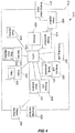
- FIG 5 a system 500 for producing a frame of a merged digital video sequence according to the present invention is illustrated.
- the system 500 comprises at least one digital network camera 110 arranged to produce the first and second digital video sequences depicting the same scene and a client 210 arranged to merge the first and second digital video sequences into a merged digital video sequence.
- the digital network camera 110 is operating as the digital network camera 110 described above.
- the client 210 is operating as the client 210 described above.
- the at least one digital network camera 110 and the client 210 are interconnected via a digital network 502.
- the system 500 may comprise a plurality of digital network cameras 110.
- the client 210 is further, via the display interface, connected to display 510 to which decoded versions of the first, the second and/or the merged digital video sequence can be sent for display.
- FIG 6 an alternative system 600 for producing a frame of a merged digital video sequence according to the present invention is illustrated.
- the system 600 comprises at least one digital network camera 110 arranged to produce the first and second digital video sequences depicting the same scene and a digital network camera 310 arranged to merge the first and second digital video sequences into a merged digital video sequence.
- the digital network camera 110 is operating as the digital network camera 110 described above.
- the digital network camera 310 is operating as the digital network camera 310 described above.
- the at least one digital network camera 110 and the digital network camera 310 are interconnected via a digital network 602.
- Figure 7 illustrates an embodiment of a method for producing a frame of a merged digital video sequence according to the present invention.
- the method comprises:
- the storing unit used for storing the merged digital video sequence may be located remote from the video processing device.
- the present invention is not limited to be used with two digital video sequences: Accordingly, any number of digital video sequences may be merged in accordance with the present invention.
- the present invention as described above is discussed in connection with monitoring video data the method of merging two digital video sequence depicting the same scene may be applied for other kinds of implementations of video data. Accordingly additionally, variations to the disclosed embodiments can be understood and effected by the skilled person in practicing the claimed invention, from a study of the drawings, the disclosure, and the appended claims.
Claims (12)
- Verfahren zum Herstellen eines Frames einer zusammengeführten digitalen Videosequenz, umfassend:Erlangen, unter Verwendung eines Bildprozessors (118; 318; 418), einer ersten digitalen Videosequenz;Analysieren, unter Verwendung einer Analyseeinheit (120; 320; 420), von Frames der ersten digitalen Videosequenz, um Pixelblöcke zu identifizieren, die als von Bedeutung erachtet werden;Herstellen, unter Verwendung eines Maskengenerators (121; 321; 421) einer Maske, die Pixelblöcke der Frames der ersten digitalen Videosequenz anzeigen, die von Bedeutung sind;Codieren, unter Verwendung einer Codiereinheit (122; 322; 422), die einen Videokompressionsalgorithmus verwendet, eines Frames der ersten digitalen Videosequenz unter Verwendung der Maske in einen Frame in einer codierten Version der ersten Videosequenz, wobei die Pixelblöcke, die als nicht von Bedeutung ausmaskiert sind, unter Verwendung von Sprungblöcken codiert werden;Decodieren, unter Verwendung eines Decoders (230; 330; 430), des codierten Frames der ersten digitalen Videosequenz;Erlangen, unter Verwendung des Bildprozessors (118; 318; 418), einer zweiten digitalen Videosequenz, wobei die ersten und zweiten digitalen Videosequenzen räumlich und zeitlich ähnlich sind und die gleiche Szene darstellen und die Frames der ersten digitalen Videosequenz eine höhere Pixelanzahl aufweisen als die Frames der zweiten digitalen Videosequenz;Skalieren, unter Verwendung eines Skalierers (234; 334; 434), eines Frames der zweiten digitalen Videosequenz, sodass ein hochskalierter Frame der zweiten digitalen Videosequenz mit der gleichen Pixelanzahl wie der Frame der ersten Videosequenz erlangt wird;Identifizieren, während der codierte Frame von der ersten digitalen Videosequenz decodiert wird und unter Verwendung einer Sprungblockkennung (232; 332; 432), einer Position für mindestens einen Sprungblock und einer Position für mindestens einen Nichtsprungblock im Frame der ersten digitalen Videosequenz;Extrahieren, unter Verwendung eines Blockextrahierers (237; 337; 437) und basierend auf der identifizierten Position für den mindestens einen Sprungblock im Frame der ersten digitalen Videosequenz, von mindestens einem entsprechenden Block von Pixeln von dem hochskalierten Frame der zweiten digitalen Videosequenz;Extrahieren, unter Verwendung des Blockextrahierers (237; 337; 437) und basierend auf der identifizierten Position für den mindestens einen Nichtsprungblock im Frame der ersten digitalen Videosequenz, von mindestens einem entsprechenden Block von Pixeln von dem Frame der ersten digitalen Videosequenz; undZusammenführen, unter Verwendung einer Zusammenführungseinheit (238; 338; 438), der extrahierten Pixelblöcke von dem Frame der zweiten digitalen Videosequenz und der extrahierten Pixelblöcke von dem Frame der ersten digitalen Videosequenz, sodass der Frame der zusammengeführten Videosequenz erzeugt wird.
- Verfahren nach Anspruch 1, ferner umfassend das Filtern, unter Verwendung eines Filters (235; 335; 435), des skalierten Frames der zweiten digitalen Videosequenz.
- Verfahren nach Anspruch 1 oder 2, wobei die Frames der zweiten digitalen Videosequenz unter Verwendung eines Videokompressionsalgorithmus codiert werden, wobei das Verfahren ferner das Decodieren, unter Verwendung des Decoders (230; 330; 430), eines Frames der zweiten digitalen Videosequenz umfasst.
- Verfahren nach einem der Ansprüche 1 bis 3, wobei der codierte Frame von der ersten digitalen Videosequenz ein INTER-Frame ist.
- Verfahren nach einem der Ansprüche 1 bis 4, wobei der Videokompressionsalgorithmus ITU-H.26X, ISO-MPEG, WMV, On2 oder WebM erfüllt.
- Verfahren nach einem der Ansprüche 1 bis 5, ferner umfassend das Speichern des Frames der zusammengeführten Videosequenz in einem Speicher (224; 324; 424).
- Verfahren nach einem der Ansprüche 1 bis 6, ferner umfassend das Wiedergeben des Frames der zusammengeführten Videosequenz.
- Computerlesbares Aufzeichnungsmedium, auf dem ein Programm zum Implementieren des Verfahrens nach einem der Ansprüche 1 bis 7 aufgezeichnet ist, das bei Ausführung auf einer Vorrichtung Verarbeitungsfähigkeiten aufweist.
- Videobearbeitungsvorrichtung (310; 410), die ausgeführt ist, das Programm, das auf dem computerlesbaren Aufzeichnungsmedium nach Anspruch 8 aufgezeichnet ist, auszuführen.
- System zum Herstellen eines Frames einer zusammengeführten digitalen Videosequenz, wobei das System umfasst:einen Bildprozessor (118; 318; 418), der ausgeführt ist, eine erste digitale Videosequenz zu erlangen;eine Analyseeinheit (120; 320; 420), die ausgeführt ist, Frames der ersten digitalen Videosequenz zu analysieren, um Pixelblöcke zu identifizieren, die als von Bedeutung erachtet werden;einen Maskengenerator (121, 321; 421), der ausgeführt ist, eine Maske auszugeben, die in den Frames der ersten digitalen Videosequenz Pixelblöcke von Bedeutung anzeigt;wobei das System ferner eine Codiereinheit umfasst (122; 322; 422), die ausgeführt ist, einen Frame der ersten digitalen Videosequenz unter Verwendung der Maske, die Pixelblöcke von Bedeutung anzeigt, in einen Frame in einer codierten Version der ersten Videosequenz zu codieren, wobei die Pixelblöcke, die als nicht von Bedeutung ausmaskiert sind, unter Verwendung von Sprungblöcken codiert werden;der Bildprozessor (118; 318; 418) ferner ausgeführt ist, eine zweite digitale Videosequenz zu erlangen, wobei die ersten und zweiten digitalen Videosequenzen räumlich und zeitlich ähnlich sind und die gleiche Szene darstellen, die Frames der ersten digitalen Videosequenz eine höhere Pixelanzahl aufweisen als die zweite digitale Videosequenz und das System ferner einen Skalierer (234; 334; 434) umfasst, der ausgeführt ist, einen Frame der zweiten digitalen Videosequenz zu skalieren, sodass ein hochskalierter Frame der zweiten digitalen Videosequenz erlangt wird, und der hochskalierte Frame der zweiten digitalen Videosequenz die gleiche Pixelanzahl wie der Frame der ersten Videosequenz aufweist;wobei das System ferner einen Decoder (230; 330; 430) umfasst, der ausgeführt ist, den codierten Frame der ersten digitalen Videosequenz zu decodieren;das System ferner eine Sprungblockkennung umfasst (232; 332; 432), die ausgeführt ist, während des Decodierens, unter Verwendung des Decoders (230; 330; 430), des codierten Frames der ersten digitalen Videosequenz, eine Position für mindestens einen Sprungblock und eine Position für mindestens einen Nichtsprungblock in dem Frame der ersten digitalen Videosequenz zu identifizieren;das System ferner einen Blockextrahierer (237; 337; 437) umfasst, der ausgeführt ist, basierend auf der identifizierten Position für den mindestens einen Sprungblock in dem Frame der ersten digitalen Videosequenz mindestens einen entsprechenden Block von Pixeln von dem hochskalierten Frame der zweiten digitalen Videosequenz und basierend auf der identifizierten Position für den mindestens einen Nichtsprungblock in dem Frame der ersten digitalen Videosequenz mindestens einen entsprechenden Block von Pixeln von dem Frame der ersten digitalen Videosequenz zu extrahieren; undeine Zusammenführungseinheit (238; 338; 438), die ausgeführt ist, die extrahierten Pixelblöcke von dem Frame der zweiten digitalen Videosequenz und die extrahierten Pixelblöcke von dem Frame der ersten digitalen Videosequenz zusammenzuführen, sodass der Frame der zusammengeführten Videosequenz erzeugt wird.
- System nach Anspruch 10, ferner umfassend einen Bildsensor (116; 316), der ausgeführt ist, eine Videosequenz einer Szene zu erfassen; und
wobei der Bildprozessor (118; 318) ausgeführt ist, die Videosequenz der Szene, die durch den Bildsensor (116; 316) erfasst wurde, in die erste und die zweite digitale Videosequenz zu verarbeiten, welche die gleiche Szene darstellen. - System nach Anspruch 10 oder 11, wobei das System in einer digitalen Videokamera (310) beinhaltet ist.
Priority Applications (3)
| Application Number | Priority Date | Filing Date | Title |
|---|---|---|---|
| EP13178768.1A EP2838268B1 (de) | 2013-07-31 | 2013-07-31 | Verfahren, Vorrichtung und System zur Herstellung einer zusammengeführten digitalen Videosequenz |
| US14/316,227 US9756348B2 (en) | 2013-07-31 | 2014-06-26 | Method, device and system for producing a merged digital video sequence |
| CN201410342453.2A CN104349074B (zh) | 2013-07-31 | 2014-07-18 | 用于生成合并的数字视频序列的方法、设备和系统 |
Applications Claiming Priority (1)
| Application Number | Priority Date | Filing Date | Title |
|---|---|---|---|
| EP13178768.1A EP2838268B1 (de) | 2013-07-31 | 2013-07-31 | Verfahren, Vorrichtung und System zur Herstellung einer zusammengeführten digitalen Videosequenz |
Publications (2)
| Publication Number | Publication Date |
|---|---|
| EP2838268A1 EP2838268A1 (de) | 2015-02-18 |
| EP2838268B1 true EP2838268B1 (de) | 2019-02-20 |
Family
ID=48875624
Family Applications (1)
| Application Number | Title | Priority Date | Filing Date |
|---|---|---|---|
| EP13178768.1A Active EP2838268B1 (de) | 2013-07-31 | 2013-07-31 | Verfahren, Vorrichtung und System zur Herstellung einer zusammengeführten digitalen Videosequenz |
Country Status (3)
| Country | Link |
|---|---|
| US (1) | US9756348B2 (de) |
| EP (1) | EP2838268B1 (de) |
| CN (1) | CN104349074B (de) |
Families Citing this family (13)
| Publication number | Priority date | Publication date | Assignee | Title |
|---|---|---|---|---|
| KR102264161B1 (ko) * | 2014-08-21 | 2021-06-11 | 삼성전자주식회사 | 이미지 처리 장치, 이미지 처리 시스템, 이미지 처리 시스템의 동작방법 및 이미지 처리 시스템을 포함하는 시스템 온 칩 |
| CN104980665A (zh) * | 2015-06-29 | 2015-10-14 | 北京金山安全软件有限公司 | 一种多视频片段合并方法及多视频片段合并装置 |
| CN105578261B (zh) * | 2015-12-18 | 2019-04-26 | 无锡天脉聚源传媒科技有限公司 | 一种视频剪辑的方法和装置 |
| US10412390B2 (en) * | 2016-07-12 | 2019-09-10 | Mediatek Inc. | Video processing system using low-cost video encoding/decoding architecture |
| EP3321844B1 (de) * | 2016-11-14 | 2021-04-14 | Axis AB | Aktionserkennung in einer videosequenz |
| US10121337B2 (en) | 2016-12-30 | 2018-11-06 | Axis Ab | Gaze controlled bit rate |
| US10123020B2 (en) * | 2016-12-30 | 2018-11-06 | Axis Ab | Block level update rate control based on gaze sensing |
| US10110802B2 (en) | 2016-12-30 | 2018-10-23 | Axis Ab | Historical gaze heat map for a video stream |
| US10643443B2 (en) | 2016-12-30 | 2020-05-05 | Axis Ab | Alarm masking based on gaze in video management system |
| US10904535B2 (en) | 2017-04-01 | 2021-01-26 | Intel Corporation | Video motion processing including static scene determination, occlusion detection, frame rate conversion, and adjusting compression ratio |
| US20190261000A1 (en) * | 2017-04-01 | 2019-08-22 | Intel Corporation | Video motion processing including static determination, occlusion detection, frame rate conversion, and adjusting compression ratio |
| US11055976B2 (en) | 2019-09-19 | 2021-07-06 | Axis Ab | Using a skip block mask to reduce bitrate from a monitoring camera |
| CN115115538A (zh) * | 2022-05-19 | 2022-09-27 | 腾讯科技(深圳)有限公司 | 视频处理方法、装置、设备及存储介质 |
Family Cites Families (46)
| Publication number | Priority date | Publication date | Assignee | Title |
|---|---|---|---|---|
| EP0476603B1 (de) * | 1990-09-20 | 1997-06-18 | Nec Corporation | Verfahren und Gerät zur Kodierung von bewegten Bildsignalen |
| US5436665A (en) * | 1992-03-03 | 1995-07-25 | Kabushiki Kaisha Toshiba | Motion picture coding apparatus |
| EP0700017B1 (de) * | 1994-08-31 | 2001-11-07 | Nippon Telegraph And Telephone Corporation | Verfahren und Gerät zum richtungsselektiven Zählen von sich bewegenden Objekten |
| US5886743A (en) * | 1994-12-28 | 1999-03-23 | Hyundai Electronics Industries Co. Ltd. | Object-by information coding apparatus and method thereof for MPEG-4 picture instrument |
| US5854856A (en) * | 1995-07-19 | 1998-12-29 | Carnegie Mellon University | Content based video compression system |
| US6680976B1 (en) * | 1997-07-28 | 2004-01-20 | The Board Of Trustees Of The University Of Illinois | Robust, reliable compression and packetization scheme for transmitting video |
| US6600786B1 (en) * | 1999-04-17 | 2003-07-29 | Pulsent Corporation | Method and apparatus for efficient video processing |
| US6611530B1 (en) * | 1999-09-21 | 2003-08-26 | Hewlett-Packard Development Company, L.P. | Video communication using multiple streams |
| US6421466B1 (en) * | 1999-09-29 | 2002-07-16 | Neomagic Corp. | Hierarchical motion estimation with levels of varying bit width for digital video compression |
| US6798424B2 (en) * | 2000-07-06 | 2004-09-28 | Fujitsu Limited | Image processing method and apparatus and storage medium |
| US7099510B2 (en) | 2000-11-29 | 2006-08-29 | Hewlett-Packard Development Company, L.P. | Method and system for object detection in digital images |
| KR100643454B1 (ko) * | 2001-11-17 | 2006-11-10 | 엘지전자 주식회사 | 영상 데이터 전송 제어방법 |
| US20040109059A1 (en) * | 2002-11-12 | 2004-06-10 | Kevin Kawakita | Hybrid joint photographer's experts group (JPEG) /moving picture experts group (MPEG) specialized security video camera |
| SE0300286D0 (sv) * | 2003-02-05 | 2003-02-05 | Axis Ab | Method and apparatus for combining video signals to one comprehensive video signal |
| EP1654864A4 (de) * | 2003-03-20 | 2009-05-27 | Ge Security Inc | Systeme und verfahren zur multistrombitverarbeitung |
| US7408986B2 (en) * | 2003-06-13 | 2008-08-05 | Microsoft Corporation | Increasing motion smoothness using frame interpolation with motion analysis |
| US7558320B2 (en) * | 2003-06-13 | 2009-07-07 | Microsoft Corporation | Quality control in frame interpolation with motion analysis |
| AU2004233453B2 (en) | 2003-12-03 | 2011-02-17 | Envysion, Inc. | Recording a sequence of images |
| JP2005286472A (ja) | 2004-03-29 | 2005-10-13 | Sanyo Electric Co Ltd | 画像処理装置および画像処理方法 |
| US7430238B2 (en) * | 2004-12-10 | 2008-09-30 | Micronas Usa, Inc. | Shared pipeline architecture for motion vector prediction and residual decoding |
| JP4464360B2 (ja) * | 2006-03-27 | 2010-05-19 | 富士フイルム株式会社 | 監視装置、監視方法、及びプログラム |
| JP5313880B2 (ja) * | 2006-04-20 | 2013-10-09 | トムソン ライセンシング | 冗長ビデオ符号化方法および装置 |
| US8250618B2 (en) * | 2006-09-18 | 2012-08-21 | Elemental Technologies, Inc. | Real-time network adaptive digital video encoding/decoding |
| JP2009049979A (ja) * | 2007-07-20 | 2009-03-05 | Fujifilm Corp | 画像処理装置、画像処理方法、画像処理システム、及びプログラム |
| EP2179589A4 (de) * | 2007-07-20 | 2010-12-01 | Fujifilm Corp | Bildverarbeitungsvorrichtung, bildverarbeitungsverfahren und programm |
| FR2923339B1 (fr) | 2007-11-05 | 2009-12-11 | Commissariat Energie Atomique | Procede de lecture d'une matrice bidimensielle de pixels et dispositif pour la mise en oeuvre d'un tel procede |
| US8121424B2 (en) | 2008-09-26 | 2012-02-21 | Axis Ab | System, computer program product and associated methodology for video motion detection using spatio-temporal slice processing |
| CN101742324A (zh) * | 2008-11-14 | 2010-06-16 | 北京中星微电子有限公司 | 视频编解码方法、视频编解码系统及编解码器 |
| US8588299B1 (en) * | 2009-01-30 | 2013-11-19 | Hewlett-Packard Development Company, L.P. | Decoding video data |
| US8532437B2 (en) * | 2009-05-18 | 2013-09-10 | Citrix Systems, Inc. | Systems and methods for block recomposition for compound image compression |
| TWI381724B (zh) | 2009-12-04 | 2013-01-01 | Vivotek Inc | Image capture and transmission device and image receiving and reassembly device |
| US20110268175A1 (en) * | 2010-04-30 | 2011-11-03 | Wai-Tian Tan | Differential protection of a live scalable media |
| US8947492B2 (en) * | 2010-06-18 | 2015-02-03 | Microsoft Corporation | Combining multiple bit rate and scalable video coding |
| US9020033B2 (en) * | 2010-11-04 | 2015-04-28 | Nice-Systems Ltd. | System and method for enhancing compression using skip macro block on a compressed video |
| WO2012097378A1 (en) * | 2011-01-14 | 2012-07-19 | General Instrument Corporation | Temporal block merge mode |
| EP2536143B1 (de) * | 2011-06-16 | 2015-01-14 | Axis AB | Verfahren und Codierungssystem für digitale Videos zum Codieren digitaler Videodaten |
| US20130080111A1 (en) * | 2011-09-23 | 2013-03-28 | Honeywell International Inc. | Systems and methods for evaluating plane similarity |
| US8953044B2 (en) * | 2011-10-05 | 2015-02-10 | Xerox Corporation | Multi-resolution video analysis and key feature preserving video reduction strategy for (real-time) vehicle tracking and speed enforcement systems |
| US20130287092A1 (en) * | 2012-04-27 | 2013-10-31 | Rovi Technologies Corporation | Systems and Methods for Adaptive Streaming with Augmented Video Stream Transitions |
| EP4250745A3 (de) * | 2012-07-09 | 2023-11-15 | Vid Scale, Inc. | Energiebewusste videocodierung und streaming |
| US9635356B2 (en) * | 2012-08-07 | 2017-04-25 | Qualcomm Incorporated | Multi-hypothesis motion compensation for scalable video coding and 3D video coding |
| EP2704427A1 (de) * | 2012-08-31 | 2014-03-05 | Axis AB | Verfahren und Vorrichtung zum Video-Deinterlacing |
| US9413985B2 (en) * | 2012-09-12 | 2016-08-09 | Lattice Semiconductor Corporation | Combining video and audio streams utilizing pixel repetition bandwidth |
| US9350970B2 (en) * | 2012-12-14 | 2016-05-24 | Qualcomm Incorporated | Disparity vector derivation |
| US9462306B2 (en) * | 2013-07-16 | 2016-10-04 | The Hong Kong University Of Science And Technology | Stream-switching in a content distribution system |
| EP3023987B1 (de) * | 2014-11-20 | 2017-03-22 | Axis AB | Verfahren und Vorrichtung zur Visualisierung von Informationen von einem Digitalvideo-Stream |
-
2013
- 2013-07-31 EP EP13178768.1A patent/EP2838268B1/de active Active
-
2014
- 2014-06-26 US US14/316,227 patent/US9756348B2/en active Active
- 2014-07-18 CN CN201410342453.2A patent/CN104349074B/zh active Active
Non-Patent Citations (1)
| Title |
|---|
| None * |
Also Published As
| Publication number | Publication date |
|---|---|
| US9756348B2 (en) | 2017-09-05 |
| CN104349074B (zh) | 2018-09-14 |
| US20150036736A1 (en) | 2015-02-05 |
| EP2838268A1 (de) | 2015-02-18 |
| CN104349074A (zh) | 2015-02-11 |
Similar Documents
| Publication | Publication Date | Title |
|---|---|---|
| EP2838268B1 (de) | Verfahren, Vorrichtung und System zur Herstellung einer zusammengeführten digitalen Videosequenz | |
| EP3402204A1 (de) | Codierung eines videostroms mit privatsphärenmaske | |
| AU2005272046B2 (en) | Method and apparatus for detecting motion in MPEG video streams | |
| EP2536143B1 (de) | Verfahren und Codierungssystem für digitale Videos zum Codieren digitaler Videodaten | |
| US20150264357A1 (en) | Method and system for encoding digital images, corresponding apparatus and computer program product | |
| US20220147567A1 (en) | Method and system for characteristic-based video processing | |
| KR20210058906A (ko) | 비디오 코딩을 위한 모션 벡터 예측자 인덱스 코딩 | |
| EP3200456A1 (de) | Videocodierungsverfahren und videocodierersystem zur zeitliche rauschminderung | |
| KR20140143328A (ko) | 디지털 비디오 데이터를 인코딩하는 방법 | |
| CN112543330B (zh) | 模糊隐私遮蔽的编码方法、系统及存储介质 | |
| EP1333682A1 (de) | Bewegungsdetektion von einem kodierten Bilddatenstrom | |
| KR102187376B1 (ko) | 딥러닝 이미지 분석과 연동하는 신택스 기반의 선별 관제 제공 방법 | |
| KR102090775B1 (ko) | 압축영상에 대한 신택스 기반의 이동객체 영역 추출 방법 | |
| KR102177494B1 (ko) | 모션벡터의 궤적 및 패턴을 이용한 압축영상의 이상모션 객체 식별 방법 | |
| CN114731440A (zh) | 视频数据的无损编码 | |
| CN105357494B (zh) | 视频编解码方法、装置 | |
| KR102061915B1 (ko) | 압축영상에 대한 신택스 기반의 객체 분류 방법 | |
| Fernandez et al. | Integrated H. 264 region-of-interest detection, tracking and compression for surveillance scenes | |
| TW202220452A (zh) | 用於視訊處理的方法及影像處理裝置 | |
| EP3989587A1 (de) | Bildverarbeitungsvorrichtung und verfahren zur vorverarbeitung von bildern eines videostroms vor der codierung | |
| GB2578151A (en) | Video coding and decoding | |
| KR102153093B1 (ko) | 컨텍스트를 고려한 압축영상에 대한 신택스 기반의 이동객체 영역 추출 방법 | |
| WO2016122540A1 (en) | Encoder | |
| KR20180003858A (ko) | 영상 요약 장치 및 영상 처리 장치 | |
| KR20230114692A (ko) | 영상 분석 방법 및 장치 |
Legal Events
| Date | Code | Title | Description |
|---|---|---|---|
| 17P | Request for examination filed |
Effective date: 20140317 |
|
| AK | Designated contracting states |
Kind code of ref document: A1 Designated state(s): AL AT BE BG CH CY CZ DE DK EE ES FI FR GB GR HR HU IE IS IT LI LT LU LV MC MK MT NL NO PL PT RO RS SE SI SK SM TR |
|
| AX | Request for extension of the european patent |
Extension state: BA ME |
|
| PUAI | Public reference made under article 153(3) epc to a published international application that has entered the european phase |
Free format text: ORIGINAL CODE: 0009012 |
|
| GRAP | Despatch of communication of intention to grant a patent |
Free format text: ORIGINAL CODE: EPIDOSNIGR1 |
|
| STAA | Information on the status of an ep patent application or granted ep patent |
Free format text: STATUS: GRANT OF PATENT IS INTENDED |
|
| INTG | Intention to grant announced |
Effective date: 20180105 |
|
| GRAS | Grant fee paid |
Free format text: ORIGINAL CODE: EPIDOSNIGR3 |
|
| GRAA | (expected) grant |
Free format text: ORIGINAL CODE: 0009210 |
|
| STAA | Information on the status of an ep patent application or granted ep patent |
Free format text: STATUS: THE PATENT HAS BEEN GRANTED |
|
| AK | Designated contracting states |
Kind code of ref document: B1 Designated state(s): AL AT BE BG CH CY CZ DE DK EE ES FI FR GB GR HR HU IE IS IT LI LT LU LV MC MK MT NL NO PL PT RO RS SE SI SK SM TR |
|
| REG | Reference to a national code |
Ref country code: GB Ref legal event code: FG4D |
|
| REG | Reference to a national code |
Ref country code: CH Ref legal event code: EP |
|
| REG | Reference to a national code |
Ref country code: DE Ref legal event code: R096 Ref document number: 602013050916 Country of ref document: DE |
|
| REG | Reference to a national code |
Ref country code: AT Ref legal event code: REF Ref document number: 1099785 Country of ref document: AT Kind code of ref document: T Effective date: 20190315 |
|
| REG | Reference to a national code |
Ref country code: IE Ref legal event code: FG4D |
|
| REG | Reference to a national code |
Ref country code: SE Ref legal event code: TRGR |
|
| REG | Reference to a national code |
Ref country code: NL Ref legal event code: MP Effective date: 20190220 |
|
| REG | Reference to a national code |
Ref country code: LT Ref legal event code: MG4D |
|
| PG25 | Lapsed in a contracting state [announced via postgrant information from national office to epo] |
Ref country code: PT Free format text: LAPSE BECAUSE OF FAILURE TO SUBMIT A TRANSLATION OF THE DESCRIPTION OR TO PAY THE FEE WITHIN THE PRESCRIBED TIME-LIMIT Effective date: 20190620 Ref country code: NO Free format text: LAPSE BECAUSE OF FAILURE TO SUBMIT A TRANSLATION OF THE DESCRIPTION OR TO PAY THE FEE WITHIN THE PRESCRIBED TIME-LIMIT Effective date: 20190520 Ref country code: FI Free format text: LAPSE BECAUSE OF FAILURE TO SUBMIT A TRANSLATION OF THE DESCRIPTION OR TO PAY THE FEE WITHIN THE PRESCRIBED TIME-LIMIT Effective date: 20190220 Ref country code: NL Free format text: LAPSE BECAUSE OF FAILURE TO SUBMIT A TRANSLATION OF THE DESCRIPTION OR TO PAY THE FEE WITHIN THE PRESCRIBED TIME-LIMIT Effective date: 20190220 Ref country code: LT Free format text: LAPSE BECAUSE OF FAILURE TO SUBMIT A TRANSLATION OF THE DESCRIPTION OR TO PAY THE FEE WITHIN THE PRESCRIBED TIME-LIMIT Effective date: 20190220 |
|
| PG25 | Lapsed in a contracting state [announced via postgrant information from national office to epo] |
Ref country code: BG Free format text: LAPSE BECAUSE OF FAILURE TO SUBMIT A TRANSLATION OF THE DESCRIPTION OR TO PAY THE FEE WITHIN THE PRESCRIBED TIME-LIMIT Effective date: 20190520 Ref country code: GR Free format text: LAPSE BECAUSE OF FAILURE TO SUBMIT A TRANSLATION OF THE DESCRIPTION OR TO PAY THE FEE WITHIN THE PRESCRIBED TIME-LIMIT Effective date: 20190521 Ref country code: IS Free format text: LAPSE BECAUSE OF FAILURE TO SUBMIT A TRANSLATION OF THE DESCRIPTION OR TO PAY THE FEE WITHIN THE PRESCRIBED TIME-LIMIT Effective date: 20190620 Ref country code: HR Free format text: LAPSE BECAUSE OF FAILURE TO SUBMIT A TRANSLATION OF THE DESCRIPTION OR TO PAY THE FEE WITHIN THE PRESCRIBED TIME-LIMIT Effective date: 20190220 Ref country code: LV Free format text: LAPSE BECAUSE OF FAILURE TO SUBMIT A TRANSLATION OF THE DESCRIPTION OR TO PAY THE FEE WITHIN THE PRESCRIBED TIME-LIMIT Effective date: 20190220 Ref country code: RS Free format text: LAPSE BECAUSE OF FAILURE TO SUBMIT A TRANSLATION OF THE DESCRIPTION OR TO PAY THE FEE WITHIN THE PRESCRIBED TIME-LIMIT Effective date: 20190220 |
|
| REG | Reference to a national code |
Ref country code: AT Ref legal event code: MK05 Ref document number: 1099785 Country of ref document: AT Kind code of ref document: T Effective date: 20190220 |
|
| PG25 | Lapsed in a contracting state [announced via postgrant information from national office to epo] |
Ref country code: RO Free format text: LAPSE BECAUSE OF FAILURE TO SUBMIT A TRANSLATION OF THE DESCRIPTION OR TO PAY THE FEE WITHIN THE PRESCRIBED TIME-LIMIT Effective date: 20190220 Ref country code: IT Free format text: LAPSE BECAUSE OF FAILURE TO SUBMIT A TRANSLATION OF THE DESCRIPTION OR TO PAY THE FEE WITHIN THE PRESCRIBED TIME-LIMIT Effective date: 20190220 Ref country code: CZ Free format text: LAPSE BECAUSE OF FAILURE TO SUBMIT A TRANSLATION OF THE DESCRIPTION OR TO PAY THE FEE WITHIN THE PRESCRIBED TIME-LIMIT Effective date: 20190220 Ref country code: EE Free format text: LAPSE BECAUSE OF FAILURE TO SUBMIT A TRANSLATION OF THE DESCRIPTION OR TO PAY THE FEE WITHIN THE PRESCRIBED TIME-LIMIT Effective date: 20190220 Ref country code: ES Free format text: LAPSE BECAUSE OF FAILURE TO SUBMIT A TRANSLATION OF THE DESCRIPTION OR TO PAY THE FEE WITHIN THE PRESCRIBED TIME-LIMIT Effective date: 20190220 Ref country code: DK Free format text: LAPSE BECAUSE OF FAILURE TO SUBMIT A TRANSLATION OF THE DESCRIPTION OR TO PAY THE FEE WITHIN THE PRESCRIBED TIME-LIMIT Effective date: 20190220 Ref country code: AL Free format text: LAPSE BECAUSE OF FAILURE TO SUBMIT A TRANSLATION OF THE DESCRIPTION OR TO PAY THE FEE WITHIN THE PRESCRIBED TIME-LIMIT Effective date: 20190220 Ref country code: SK Free format text: LAPSE BECAUSE OF FAILURE TO SUBMIT A TRANSLATION OF THE DESCRIPTION OR TO PAY THE FEE WITHIN THE PRESCRIBED TIME-LIMIT Effective date: 20190220 |
|
| REG | Reference to a national code |
Ref country code: DE Ref legal event code: R097 Ref document number: 602013050916 Country of ref document: DE |
|
| PG25 | Lapsed in a contracting state [announced via postgrant information from national office to epo] |
Ref country code: PL Free format text: LAPSE BECAUSE OF FAILURE TO SUBMIT A TRANSLATION OF THE DESCRIPTION OR TO PAY THE FEE WITHIN THE PRESCRIBED TIME-LIMIT Effective date: 20190220 Ref country code: SM Free format text: LAPSE BECAUSE OF FAILURE TO SUBMIT A TRANSLATION OF THE DESCRIPTION OR TO PAY THE FEE WITHIN THE PRESCRIBED TIME-LIMIT Effective date: 20190220 |
|
| PLBE | No opposition filed within time limit |
Free format text: ORIGINAL CODE: 0009261 |
|
| STAA | Information on the status of an ep patent application or granted ep patent |
Free format text: STATUS: NO OPPOSITION FILED WITHIN TIME LIMIT |
|
| PG25 | Lapsed in a contracting state [announced via postgrant information from national office to epo] |
Ref country code: AT Free format text: LAPSE BECAUSE OF FAILURE TO SUBMIT A TRANSLATION OF THE DESCRIPTION OR TO PAY THE FEE WITHIN THE PRESCRIBED TIME-LIMIT Effective date: 20190220 |
|
| 26N | No opposition filed |
Effective date: 20191121 |
|
| PG25 | Lapsed in a contracting state [announced via postgrant information from national office to epo] |
Ref country code: SI Free format text: LAPSE BECAUSE OF FAILURE TO SUBMIT A TRANSLATION OF THE DESCRIPTION OR TO PAY THE FEE WITHIN THE PRESCRIBED TIME-LIMIT Effective date: 20190220 Ref country code: MC Free format text: LAPSE BECAUSE OF FAILURE TO SUBMIT A TRANSLATION OF THE DESCRIPTION OR TO PAY THE FEE WITHIN THE PRESCRIBED TIME-LIMIT Effective date: 20190220 |
|
| REG | Reference to a national code |
Ref country code: CH Ref legal event code: PL |
|
| PG25 | Lapsed in a contracting state [announced via postgrant information from national office to epo] |
Ref country code: TR Free format text: LAPSE BECAUSE OF FAILURE TO SUBMIT A TRANSLATION OF THE DESCRIPTION OR TO PAY THE FEE WITHIN THE PRESCRIBED TIME-LIMIT Effective date: 20190220 |
|
| REG | Reference to a national code |
Ref country code: BE Ref legal event code: MM Effective date: 20190731 |
|
| PG25 | Lapsed in a contracting state [announced via postgrant information from national office to epo] |
Ref country code: LU Free format text: LAPSE BECAUSE OF NON-PAYMENT OF DUE FEES Effective date: 20190731 Ref country code: BE Free format text: LAPSE BECAUSE OF NON-PAYMENT OF DUE FEES Effective date: 20190731 Ref country code: CH Free format text: LAPSE BECAUSE OF NON-PAYMENT OF DUE FEES Effective date: 20190731 Ref country code: LI Free format text: LAPSE BECAUSE OF NON-PAYMENT OF DUE FEES Effective date: 20190731 |
|
| PG25 | Lapsed in a contracting state [announced via postgrant information from national office to epo] |
Ref country code: IE Free format text: LAPSE BECAUSE OF NON-PAYMENT OF DUE FEES Effective date: 20190731 |
|
| PG25 | Lapsed in a contracting state [announced via postgrant information from national office to epo] |
Ref country code: CY Free format text: LAPSE BECAUSE OF FAILURE TO SUBMIT A TRANSLATION OF THE DESCRIPTION OR TO PAY THE FEE WITHIN THE PRESCRIBED TIME-LIMIT Effective date: 20190220 |
|
| PG25 | Lapsed in a contracting state [announced via postgrant information from national office to epo] |
Ref country code: MT Free format text: LAPSE BECAUSE OF FAILURE TO SUBMIT A TRANSLATION OF THE DESCRIPTION OR TO PAY THE FEE WITHIN THE PRESCRIBED TIME-LIMIT Effective date: 20190220 Ref country code: HU Free format text: LAPSE BECAUSE OF FAILURE TO SUBMIT A TRANSLATION OF THE DESCRIPTION OR TO PAY THE FEE WITHIN THE PRESCRIBED TIME-LIMIT; INVALID AB INITIO Effective date: 20130731 |
|
| PG25 | Lapsed in a contracting state [announced via postgrant information from national office to epo] |
Ref country code: MK Free format text: LAPSE BECAUSE OF FAILURE TO SUBMIT A TRANSLATION OF THE DESCRIPTION OR TO PAY THE FEE WITHIN THE PRESCRIBED TIME-LIMIT Effective date: 20190220 |
|
| P01 | Opt-out of the competence of the unified patent court (upc) registered |
Effective date: 20230505 |
|
| PGFP | Annual fee paid to national office [announced via postgrant information from national office to epo] |
Ref country code: FR Payment date: 20230621 Year of fee payment: 11 |
|
| PGFP | Annual fee paid to national office [announced via postgrant information from national office to epo] |
Ref country code: SE Payment date: 20230622 Year of fee payment: 11 |
|
| PGFP | Annual fee paid to national office [announced via postgrant information from national office to epo] |
Ref country code: GB Payment date: 20230620 Year of fee payment: 11 |
|
| PGFP | Annual fee paid to national office [announced via postgrant information from national office to epo] |
Ref country code: DE Payment date: 20230620 Year of fee payment: 11 |