EP2008243B1 - System zur vorbereitung eines bildes zur segmentierung - Google Patents
System zur vorbereitung eines bildes zur segmentierung Download PDFInfo
- Publication number
- EP2008243B1 EP2008243B1 EP07760804A EP07760804A EP2008243B1 EP 2008243 B1 EP2008243 B1 EP 2008243B1 EP 07760804 A EP07760804 A EP 07760804A EP 07760804 A EP07760804 A EP 07760804A EP 2008243 B1 EP2008243 B1 EP 2008243B1
- Authority
- EP
- European Patent Office
- Prior art keywords
- image
- filters
- images
- fluorescent
- receiving device
- Prior art date
- Legal status (The legal status is an assumption and is not a legal conclusion. Google has not performed a legal analysis and makes no representation as to the accuracy of the status listed.)
- Active
Links
Images

Classifications
-
- G—PHYSICS
- G06—COMPUTING OR CALCULATING; COUNTING
- G06V—IMAGE OR VIDEO RECOGNITION OR UNDERSTANDING
- G06V20/00—Scenes; Scene-specific elements
- G06V20/60—Type of objects
- G06V20/69—Microscopic objects, e.g. biological cells or cellular parts
- G06V20/695—Preprocessing, e.g. image segmentation
-
- A—HUMAN NECESSITIES
- A61—MEDICAL OR VETERINARY SCIENCE; HYGIENE
- A61B—DIAGNOSIS; SURGERY; IDENTIFICATION
- A61B5/00—Measuring for diagnostic purposes; Identification of persons
- A61B5/72—Signal processing specially adapted for physiological signals or for diagnostic purposes
- A61B5/7235—Details of waveform analysis
- A61B5/7253—Details of waveform analysis characterised by using transforms
- A61B5/726—Details of waveform analysis characterised by using transforms using Wavelet transforms
-
- G—PHYSICS
- G06—COMPUTING OR CALCULATING; COUNTING
- G06T—IMAGE DATA PROCESSING OR GENERATION, IN GENERAL
- G06T7/00—Image analysis
- G06T7/10—Segmentation; Edge detection
- G06T7/11—Region-based segmentation
-
- G—PHYSICS
- G06—COMPUTING OR CALCULATING; COUNTING
- G06T—IMAGE DATA PROCESSING OR GENERATION, IN GENERAL
- G06T7/00—Image analysis
- G06T7/10—Segmentation; Edge detection
- G06T7/143—Segmentation; Edge detection involving probabilistic approaches, e.g. Markov random field [MRF] modelling
-
- G—PHYSICS
- G06—COMPUTING OR CALCULATING; COUNTING
- G06T—IMAGE DATA PROCESSING OR GENERATION, IN GENERAL
- G06T7/00—Image analysis
- G06T7/40—Analysis of texture
- G06T7/41—Analysis of texture based on statistical description of texture
- G06T7/42—Analysis of texture based on statistical description of texture using transform domain methods
-
- G—PHYSICS
- G06—COMPUTING OR CALCULATING; COUNTING
- G06V—IMAGE OR VIDEO RECOGNITION OR UNDERSTANDING
- G06V10/00—Arrangements for image or video recognition or understanding
- G06V10/40—Extraction of image or video features
- G06V10/52—Scale-space analysis, e.g. wavelet analysis
-
- G—PHYSICS
- G06—COMPUTING OR CALCULATING; COUNTING
- G06T—IMAGE DATA PROCESSING OR GENERATION, IN GENERAL
- G06T2207/00—Indexing scheme for image analysis or image enhancement
- G06T2207/10—Image acquisition modality
- G06T2207/10056—Microscopic image
-
- G—PHYSICS
- G06—COMPUTING OR CALCULATING; COUNTING
- G06T—IMAGE DATA PROCESSING OR GENERATION, IN GENERAL
- G06T2207/00—Indexing scheme for image analysis or image enhancement
- G06T2207/20—Special algorithmic details
- G06T2207/20048—Transform domain processing
- G06T2207/20064—Wavelet transform [DWT]
-
- G—PHYSICS
- G06—COMPUTING OR CALCULATING; COUNTING
- G06T—IMAGE DATA PROCESSING OR GENERATION, IN GENERAL
- G06T2207/00—Indexing scheme for image analysis or image enhancement
- G06T2207/30—Subject of image; Context of image processing
- G06T2207/30004—Biomedical image processing
- G06T2207/30024—Cell structures in vitro; Tissue sections in vitro
Definitions
- This invention relates to a system for preparing an image for segmentation.
- live cells or microorganisms are examined to determine their characteristics they are placed under a microscope for analysis. Live cells are analyzed to find cures for many illnesses or diseases that exist today, such as cancer. For example, a person or scientist may put a breast lymph node cell on a specimen plate under a microscope to determine how the lymph node cell functions under various conditions in order to discover a method for treating the lymph node cell so it will not be cancerous.
- a microscope that may be utilized to view cell function is a fluorescent microscope and the like.
- the typical fluorescent microscope utilizes a light source to transmit light through a dichroic mirror to excite fluorescent dyes in stained living cells or a sample specimen that absorbs radiation from the light and emits radiation at a lower frequency, whereby this emitted light will be reflected back through the dichroic mirror to an optical detector.
- the optical detector will then receive an image of the living cells. Normally, the optical detector will send the image to a computer that would reconstruct the image of the living cells based on an algorithm or equation.
- phase contrast microscopy is a contrast enhancing optical technique that can be utilized for generating high-contrast images of transparent specimens such as living cells, microorganisms and sub-cellular particles.
- This phase contrast technique employs an optical mechanism to translate minute variations in phase into corresponding changes in amplitude, which can be visualized as differences in image contrast.
- This type of microscopy enables one to observe low-contrast specimens that are either transparent or semi-transparent, which is often difficult, especially without proper illumination.
- the application of suitable contrast enhancement provides a substantial increase in contrast of barely visible low-contrast specimens in positive or negative relief.
- the illumination utilized by the phase contrast microscopy is standard brightfield transmitted light, oblique brightfield transmitted light and single-sided darkfield illumination.
- standard brightfield transmitted light for illumination he avoids harmful exposure of the specimens to toxic dyes associated with staining living cells so the specimens will not die.
- the problem with utilizing this type of illumination is that brightfield images of the specimens look colorless and washed out.
- in order to ensure that the specimen does not die it is necessary to keep the level of exposure the specimen receives from harmful light and bleaching to a minimum.
- low intensity inevitably leads to noise being a severe problem.
- DIC microscopy is a mechanism for increasing contrast in transparent specimens.
- DIC microscopy is a beam-shearing interference system in which the reference beam is sheared by a miniscule amount. This technique produces a monochromatic shadow-cast image that effectively displays the gradient of optical paths for both high and low spatial frequencies present in the specimen.
- the regions of the specimen where the optical paths increase along a reference direction appear brighter (or darker), while regions where the path differences decrease appear in reverse contrast.
- image contrast is dramatically increased.
- this type of microscopy enables one to observe low-contrast specimens that are either transparent or semi-transparent, which is often difficult especially without proper illumination.
- This DIC microscopy also utilizes standard brightfield transmitted light that causes the same problems discussed above for the phase contrast microscopy.
- the condenser For brightfield transmitted light microscopes, light is aimed toward a lens beneath a stage called the condenser, through the sample specimen, through an objective lens, and to the eye through a second magnifying lens, the ocular or eyepiece.
- the object to be inspected is normally placed on a clear glass slide and light is transmitted through the object, which makes the object appear against a bright background hence the term "brightfield.”
- the objects in the light path are seen because natural pigmentation or stains absorb light differentially, or because they are thick enough to absorb a significant amount of light despite being colorless.
- the interior of the cells in the brightfield image is barely discernible so one can not tell the difference between the cells and the background. Also, the noise is a severe problem which inhibits segmentation of the cell.
- HILL P R ET AL Rotationally invariant texture features using the dual-tree complex wavelet transform" IMAGE PROCESSING, 2000. PROCEEDINGS 2000 INTERNATIONAL CONFERENCE ON SEPTEMBER 10-13, 2000, PISCATAWAY, NJ, USA, IEEE, vol.
- the present invention has been accomplished in view of the above-mentioned technical background, and it is an object of the present invention to provide a simple method for preparing an image for segmentation.
- a system for preparing an image for segmentation is disclosed.
- An image transmitting device is configured to transmit a first image to an image receiving device.
- the image receiving device is configured to: receive the first image; apply a Dual Tree Complex Wavelet transform to the first image to form a plurality of sub-images; generate a high pass image based on the plurality of sub-images; generate a rotational invariant resultant image based on the high pass image; generate a low pass image based on the plurality of sub-images; and combine the rotational invariant resultant image and the low pass image to form a pseudo-fluorescent image.
- an apparatus for preparing an image for segmentation is disclosed.
- a connection interface is configured to receive a first image; the connection interface is coupled to a mass storage, wherein the mass storage is configured to: receive the first image; apply a Dual Tree Complex Wavelet transform to the first image to form a plurality of sub-images; generate a high pass image based on the plurality of sub-images; generate a rotational invariant resultant image based on the plurality of sub-images; generate a low pass image based on the plurality of sub-images; and combine the rotational invariant resultant image and the low pass image to form a pseudo-fluorescent image.
- a method for preparing an image for segmentation is disclosed.
- a first image is received.
- a Dual Tree Complex Wavelet Transform is applied to the first image to form a plurality of sub- images.
- a high pass image is generated based on the plurality of sub-images.
- a rotational invariant resultant image is generated based on the high pass image
- a low pass image is generated based on the plurality of sub-images. The rotational invariant resultant image and the low pass image are combined to form a pseudo-fluorescent image.
- a computer-readable medium that is configured to prepare an image for segmentation.
- a first image is received.
- a Dual Tree Complex Wavelet Transform is applied to the first image to form a plurality of sub-images.
- a high pass image is generated based on the plurality of sub-images.
- a rotational invariant resultant image is generated based on the high pass image.
- a low pass image is generated based on the plurality of sub-images. The rotational invariant resultant image and the low pass image are combined to form a pseudo-fluorescent image.
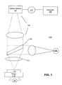
- FIG. 1 illustrates a block diagram of a segmentation system in accordance with an embodiment of the invention.
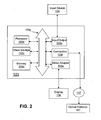
- FIG. 2 is a schematic diagram of an image receiving device of the segmentation system of FIG. 1 in accordance with the invention.
- FIG. 3 is an example of a brightfield image in accordance with the invention.
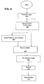
- FIG. 4 depicts a flow chart of how an image is prepared for segmentation in accordance with the invention.
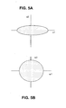
- FIG. 5A depicts feature vectors of the image of FIG. 3 in accordance with the invention.
- FIG. 5B depicts whitened feature vectors of the image of FIG. 3 in accordance with the invention.
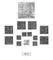
- FIG. 6 illustrates an example image and decompositions of the image into sub-images in accordance with the invention.
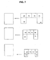
- FIG. 7 illustrates decompositions of sub-images and rescaling of the image of FIG. 6 in accordance with the invention.
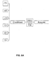
- FIG. 8A depicts a rescaling of the high pass filter six sub-images in accordance with the invention.
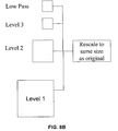
- FIG. 8B depicts a rescaling of the low pass filter sub-image in accordance with the invention.
- FIG. 9A illustrates a cytoplasm image with noise in accordance with the invention.
- FIG. 9B illustrates the cytoplasm image of FIG. 9A where noise has been removed in accordance with the invention.
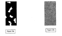
- FIG. 10A is an example of the brightfield image of FIG. 3 that is transformed into a pseudo-fluorescent image in accordance with the invention.
- FIG. 10B is another example of a brightfield image where the image has been transformed into a pseudo-fluorescent image.
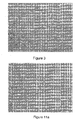
- FIG. 11A illustrates an image of FIG. 3 , where the noise has been removed.
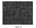
- FIG. 11B illustrates a pseudo-fluorescent image of FIG. 11A , where this pseudo-fluorescent image is in a form suitable for segmentation, using techniques developed for processing fluorescent (stained) images.
- FIG. 1 illustrates a block diagram of a segmentation system of the invention.
- This segmentation system 100 includes a conventional fluorescent microscope system 101 electrically or wirelessly connected by a communication link 117 to a conventional computer 103.
- the communication link 117 may be a local access network (LAN), a wireless local network, a wide area network (WAN), a metropolitan area network, a virtual area network, a universal service bus (USB), an Ethernet link, a satellite link, cable, cellular, twisted-pair, fiber-optic or any network that is able to facilitate the transfer of data between the fluorescent microscope system 101 and the computer 103.
- LAN local access network
- WAN wide area network
- USB universal service bus
- Ethernet link a satellite link, cable, cellular, twisted-pair, fiber-optic or any network that is able to facilitate the transfer of data between the fluorescent microscope system 101 and the computer 103.
- Fluorescent microscope system 101 includes a light source 105, an optical detector 107, a scanning mirror 109, an objective lens 111, an object stage 113 and a sample specimen 115.
- Fluorescent microscope system 100 may be referred to as an image transmitting device that is capable of capturing an image, by utilizing the optical detector 107, of the sample specimen 115 or any type of object that is placed on the object stage 113.
- the sample specimen 115 may be live biological organisms, biological cells, bacteria, De-Ribo Nucleic Acid, nucleic acid or the like.
- the fluorescent microscope system 101 may be a typical fluorescent microscope, phase contrast microscope, differential interference contrast microscope, or a microscope known to those of ordinary skill in the art. In another embodiment, the fluorescent microscope system 101 may be a typical high throughput assay that is able to rapidly detect, analyze and provide images of biological organisms or the like.
- the light source 105 may be a laser, a plurality of lasers or any type of lighting device known to those of ordinary skill that provides excitation light to force the fluorescent dyes in the sample specimen 115 to emit light from the stained portions of the sample specimen 115.
- fluorescent dye molecules are inserted into the sample specimen 115 or the sample specimen is stained, whereby when the excitation light of the light source 105 contacts the sample specimen 115 then the fluorescent dyes in the sample specimen 115 absorb the light or radiation of the frequency of the light and emit an illumination light or radiation at a lower fixed frequency.
- this microscope is a brightfield microscope, where light 102 is aimed toward a lens beneath the object stage 113 called the condenser (not shown), through the sample specimen 105, through the objective lens 111, and to the eye through a second magnifying lens, the ocular or key piece as described previously.
- Scanning mirror 109 is located above the sample 115, this scanning mirror 109 operates as a typical scanning mirror that is able to receive the light or excitation light from the light source 105, then transfer the light through the objective lens to cause the fluorescent dye in the sample specimen 115 to emit fluorescent light or illumination light that is transmitted back through the objective lens 111 and the scanning mirror 109 to the optical detector 107.
- the scanning mirror 109 may also be referred to as a dichroic mirror 109, which reflects light shorter than a certain wavelength and passes light longer than that wavelength.
- the optical detector 107 that receives the illumination light may be a photomultiplier tube, a charged coupled device (CCD), a complementary metal-oxide semiconductor (CMOS) image detector or any optical detector utilized by those of ordinary skill in the art.
- Optical detector 107 as stated above, is electrically or wirelessly connected by the communication link 117 to the computer 103.
- the computer 103 may be referred to as an image receiving device 103, image detection device 103 or a high throughput screening device.
- image receiving device 103 may be located inside of the image transmitting device 101.
- the image receiving device 103 acts as a typical computer, which is capable of receiving an image of the sample specimen 115 from the optical detector 107, then the image receiving device 103 is able to build up or reconstruct the image by utilizing a standard image processing software program, algorithm or equation usually one pixel at a time.
- the computer 103 may be a personal digital assistant (PDA), laptop computer, notebook computer, mobile telephone, hard-drive based device or any device that can receive, send and store information through the communication link 117.
- PDA personal digital assistant
- FIG. 2 illustrates a schematic diagram of the image receiving device of the segmentation system of FIG. 1 .
- Imaging receiving device 103 includes the typical components associated with a conventional computer.
- the imaging receiving device 103 includes: a processor 103a, an input/output (I/O) controller 103b, a mass storage 103c, a memory 103d, a video adapter 103e, a connection interface 103f and a system bus 103g that operatively, electrically or wirelessly, couples the aforementioned systems components to the processor 103a.
- the system bus 103g electrically or wirelessly, operatively couples typical computer system components to the processor 103a.
- the processor 103a may be referred to as a processing unit, a central processing unit (CPU), a plurality of processing units or a parallel processing unit.
- System bus 103g may be a typical bus associated with a conventional computer.
- Memory 103d includes a read only memory (ROM) and a random access memory (RAM).
- ROM includes a typical input/output system including basic routines, which assists in transferring information between components of the computer during start-up.
- the mass storage 103c which includes: 1.a hard disk drive component (not shown) for reading from and writing to a hard disk and a hard disk drive interface (not shown), 2. a magnetic disk drive (not shown) and a hard disk drive interface (not shown) and 3. an optical disk drive (not shown) for reading from or writing to a removable optical disk such as a CD- ROM or other optical media and an optical disk drive interface (not shown).
- the aforementioned drives and their associated computer readable media provide non-volatile storage of computer-readable instructions, data structures, program modules and other data for the computer 103.
- the aforementioned drives include the preparation of an image for segmentation image algorithm, software or equation of this invention or a preprocessing operation for the image, which will be described in the flow chart of FIG. 4 that works with the processor 103 to reconstruct an image of living cells.
- the preparation of an image for segmentation algorithm, software or equation may be stored in the processor 103a, memory 103d or any other part of the image receiving device 103 known to those of ordinary skill in the art.
- Input/output controller 103b is connected to the processor 103a by the bus 103g, where the input/output controller 103b acts as a serial port interface that allows a user to enter commands and information into the computer through input device 104, such as a keyboard and pointing devices.
- the typical pointing devices utilized are joysticks, mouse, game pads or the like.
- a display 106 is electrically or wirelessly connected to the system bus 103g by the video adapter 103e.
- Display 106 may be the typical computer monitor, Liquid Crystal Display, High-Definition TV (HDTV), projection screen or a device capable of having characters and/or still images generated by a computer 103.
- the connection interface 103f Next to the video adapter 103e of the computer 103, is the connection interface 103f.
- connection interface 103f may be referred to as a network interface which is connected, as described above, by the communication link 117 to the optical detector 107.
- the image receiving device 103 may include a network adapter or a modem, which enables the image receiving device 103 to be coupled to other computers.
- FIG. 3 is an example of an image that is segmented and reconstructed.
- This image is an example of a typical brightfield image described above.
- This particular brightfield image depicts live cells, but brightfield images may depict biological organisms, nucleic acid, organic tissue or the like.
- the live cells to be inspected are normally placed on a clear glass slide and light is transmitted through the cells, which makes the cells appear against a bright background hence the term "brightfield.”
- the cells in the light path are seen because natural pigmentation or stains absorb light differentially, or because they are thick enough to absorb a significant amount of light despite being colorless.
- the interior of the cells in the brightfield image is barely-discernible so one can not tell the difference between the cells and the background.
- the image was corrected and adjusted with respect to contrast, brightness, sharpness, hue, color balance, and saturation using digital image processing tools available on software stored in computer 103.
- FIG. 4 is a flow chart that depicts an example of how an image is prepared for segmentation.
- This operation of the preparation for segmentation of an image refers to preparing a brightfield image of FIG. 3 for segmentation, but this preparation for segmentation system also may be utilized to prepare the following types of image for segmentation: a transparent image, a phase contrast image, a differential-interference-contrast (DIC) microscopy image, any image associated with a microscope system 101 or a high throughput assay 101, any type of pixel generated image or any image.
- An image of the sample specimen 115 ( FIG. 1 ) is taken by optical detector 107 of the image transmitting device 101.
- this preparation for segmentation system refers to a software, algorithm or equation of this invention stored on mass storage 103c that works with the processor 103 labels regions of the living cells and prepares a simplified model of the image wherein neighboring pixels are labeled to the same.
- the preparation for segmentation image algorithm, software or equation may be stored in the processor 103a, memory 103d or any other part of the image receiving device 103 known to those of ordinary skill in the art.
- the preparation for segmentation software, algorithm or equation is stored on a computer-readable medium that includes computer-executable instructions.
- the computer-readable medium includes a floppy disk, optical disc, digital video disk, computer disk read only memory (CD-ROM) and the like.
- the image is transferred by the optical detector 107 through the communication link 117 by the connection interface 103f ( FIG. 2 ) where the image is received at the image receiving device 103.
- a Dual Tree Wave Complex Transform (DTWCT) is applied to the image.
- DTWCT Dual Tree Wave Complex Transform
- the image is transformed by utilizing the Dual Tree Complex Wavelet Transform (DTWCT).
- DTWCT Dual Tree Complex Wavelet Transform
- the image received at the image receiving device 103 is decomposed into two to twelve sub images or plurality of sub images by applying and providing the known Dual Tree Complex Wavelet Transform.
- Hatipoglu, Serkan, Kingsbury Nick and Mitra Sanjit "Texture Classification Using Dual-Tree Complex Wavelet Transform", Image Processing and Its Applications, Conference Publication No. 465, 1999 which is herein incorporated by reference.
- the image is decomposed into six sub-images based on a set of filters or a plurality of filters that are repeatedly applied to the image to discern details of the image at different scales.
- the number of filters repeatedly applied to the image can be from two to twelve filters.
- filters are repeatedly applied to filter the image into six sub images.
- six sub-images of an image of a bridge are taken based on the image being applied to filters of low pass filters and high pass filters or any other combination thereof depending on the person utilizing the pointing device 104 ( FIG. 2 ) to determine what filters should be utilized to filter the image.
- the filters can also be quadrature shifting filters, odd length biorthogonal filters, LeGall filters, Near-Symmetric filters, Antonini filters, quarter sample shift orthogonal filters, complex filters and the like.
- the high pass filter discerns fine detail of the image and low pass filter sees the average behavior of the image.
- These filters are chosen so that the combination of low and high pass images will result in a reconstruction of the original image where no information is lost. Thereafter, for this process it is normal to repeat the process by utilizing only the low pass filter component.
- These 6 sub images for the low pass filter are repeatedly broken down into smaller and smaller components, which constitute the typical pyramid decomposition as shown in FIG. 6 .
- This breakdown of sub images is the standard recursive breakdown of low pass sub-images.
- other types of recursive breakdown of low pass sub-images include quadtree decomposition that can also be utilized by this embodiment.
- the six sub-images are filtered with complex conjugates of the column and rows filters.
- These six sub images are in two adjacent spectral quadrants, having real and imaginary coefficients, which are oriented at angles from left to right -15 degrees, -45 degrees, -75 degrees, 75 degrees, 45 degrees and 15 degrees as shown in FIG. 7 .
- the strong orientation occurs because the complex filters are symmetry responses.
- These complex filters can separate positive frequencies from negative ones vertically and horizontally so positive and negative frequencies are not aliased.
- each level application of the DTCWT yields six detail images (high pass images) and one smooth image (low pass image).
- the DTCWT is further applied to the smooth image to yield six more detail images at the next level and yet another, smaller, smooth image.
- the process can be repeated to some predetermined number of levels. Each level corresponds to a different scale.
- the first time the DTCWT is applied the six detail images comprise the finest detail only viewable at the highest magnification. Cell structures at this scale could comprise granules and mitochondria, for example.
- the next application of the DTCWT will yield features at a lower order of detail, such as nuclei, for example.
- the Dual Tree Complex Wavelet Transform offers several benefits.
- the transform provides approximate shift invariance.
- the transform provides good directional selectivity in 2D Gabor like filters.
- the selectivity provides some sensitivity to shape and edges of the living cells of sample specimen 115 that will be depicted in the reconstructed image of the sample specimen 115 so the true shape of the living cells may be shown, which depicts the texture of the sample specimen.
- the image of the living cells is improved by using the short linear phase filters associated with the Dual Tree Complex Wavelet Transform.
- Linear phase avoids phase distortion by making phase changes introduced by the filter proportional to frequency.
- the term "short” refers to fast because less computation is involved when using short filters.
- redundancy in a wavelet transform whilst bad in image compression, can be good for avoiding artifacts. It is this property that leads to translation variance.
- this transform has directionality that is good because it avoids checkerboard artifacts that occur when using horizontal/vertical filters.
- the method used to generate invariant representation is as follows; At each level of the pyramid decomposition, the response of the 6 high pass sub-images is combined in some non-order specific manner to make a composite image of the same size as in FIG. 8A . The resultant image is approximately rotationally invariant. To combine the images one may choose the sum of the absolute values, this being independent of order. Another choice would be the maximum value of the 6. The sum of the squares is another option.
- the resultant image has to be resized to the size of the original image to facilitate the construction of feature vectors (as discussed later).
- image resizing There are several typical methods that may be utilized for image resizing, which range from the standard methods such as nearest neighbors, bilinear or bicubic resizing to the more exotic methods using image transformations such as the Discrete Cosine Transform (DCT) and Fast Fourier Transform (FFT).
- DCT Discrete Cosine Transform
- FFT Fast Fourier Transform
- the inverse DTCWT can also be used to resize sub-images. In this case, all the sub-images are set to zero except the current image.
- the result of the inverse DTWCT image rescaled will show the individual contribution of the current sub-image to in comparison to the original image at full size where detail is preserved.
- the last choice of resizing algorithm would be the choice of the purist.
- the high pass image and the low pass image are combined to implement deshading as well as a certain degree of cell declumping.
- the symbol H refers to the high pass image and L refers to the low pass image.
- FIG. 3 illustrates a DIC image that includes noise and the creases that will be removed by using deshading.
- H/L the dimensionless quantity
- I BF represents the output of a pseudo-fluorescent image
- H represents the high pass filtered image
- L represents the low pass filtered image
- the astute reader will recognize the similarity to a Wiener Filter (The Wiener Filter is the optimal Least Squares solution used in inverse filtering that avoids dividing by zero). This is a dimensionless quantity that is independent of multiplicative variations in image intensity across the image. Moreover, when L is zero I BF is also zero. This last, point actually helps to declump cells which otherwise would be joined because high pass filters would mistakenly see cell boundaries as texture. Thus, the low pass image and the high pass image and the low pass image are recombined to form a pseudo-fluorescent image at block 409.
- Feature vectors are derived from the approximately rotation invariant features constructed above when sub-images were resized to the size of the original image. For each pixel in the original image there is a corresponding feature in each rotationally invariant sub-image. Therefore, we can define a feature vector for each pixel in the original image by selecting as an element the corresponding pixel in each of the rescaled images.
- the pixel of a pseudo-fluorescent image is derived from the corresponding feature vector by a simple feature summarization process.
- the feature vectors yielded by the procedure described herein can be summarized in one dimensional form by the vector magnitude. This quantity suffices to distinguish cell constructs from image background.
- the feature extraction process entails extracting the raw data from the image or array of pixels and defining an attribute of the image or array of pixels such as a location where cells are located on the array of pixels. For example, the location of a certain array of pixels may be on a top portion or a bottom portion of the image. The top and bottom portion of the image containing the array of pixels will be assigned a class or labeled. At this point the magnitude of the feature vector is obtained.
- Each vector is classified so that each point in the vector is able to form a reconstructed image of the brightfield image of FIG. 3 .
- There are several different well known methods employed to classify the vectors such as clustering feature vectors, mapping plurality of feature vectors to 1-dimensional space and utilizing Markov Random Fields.
- mapping feature vector to 1D will be utilized where each vector is translated into a single number.
- a combination of the aforementioned well known methods used to classify the vectors may be employed to transform the vector into a single number.
- the feature vectors may be clustered using a priority queue where a seeded region growing algorithm can be implemented by placing image pixels (and their corresponding feature vectors) on the queue and growing them according to fitness.
- the fitness measure depends on the similarity of feature vectors in neighboring pixels to the feature vector of the current pixel.
- Feature vectors may also be clustered using standard techniques such as K-means, bisecting K-means or support vector machines.
- the standard method of seeking a good solution as opposed to an optimal solution for clustering feature vectors occurs by sampling from the Posterior Distribution using Gibbs sampling or some other means of sampling a posterior density, which is familiar method known to those ordinary skill in the art.
- BayesShrink denoising is an adaptive data-driven threshold for image denoising via wavelet soft-thresholding.
- BayesShrink denoising shrinks magnitude of wavelets, so the small noisy ones end up having a zero magnitude.
- GMD generalized Gaussian distribution
- the feature vectors are compressed into a plurality of pixels whose brightness depends on local texture.
- mapping feature vector to 1 dimension will be utilized where each vector is translated into a single number. This particular translation of a vector into a single number is utilized in conjunction with the well known Mahalanobis Distance.
- Each feature vector of the plurality of low frequency sub-images and plurality of high frequency sub-images are illustrated by the values v1 and v2 (v) representing typical x and y coordinates on a 2-dimensional graph as shown in FIG. 5A where the feature vectors form an ellipsoidal shape. Even though an ellipsoidal shape is utilized in this example the feature vectors of the image may form any shape.
- the standard Mahalanobis equation is utilized to produce associated whitened feature vectors w1 and w2 (w), representing typical x and y components on a 2-dimensional graph where w correlates to the value v as shown in FIG. 5B .
- the Mahalanobis metric is used as a means to convert feature vectors into a representation where one can calculate the magnitude of a feature vector.
- the feature vectors v are changed into whitened feature vectors w where the image depicted has a circular shape.
- Circles are associated with an L2 norm (or Euclidean norm) one could substitute other shapes such as square (L infinity or Metropolis norm) or diamond (L1 norm) in place of the circular shape in order to depict the change of the featured vectors v to the whitened feature vectors w.
- This Mahalanobis distance equation computes covariance matrix (C -1 ) of features of the vector whitens feature vectors and normalizes the feature vectors.
- the covariance matrix is a matrix of covariances between elements of the feature vector v. Covariance is the measure of how much two variables vary together, which means the covariance becomes more positive for each pair of values which differ from their mean in the same direction, and becomes more negative with each pair of values which differ from their mean in opposite direction. In this way, the more often they differ in the same direction, the more positive the covariance, and the more often they differ in opposite directions, the more negative the covariance. After applying a whitening transform the covariance matrix is, by definition, given by the
- FIG. 10A illustrates a pseudo- fluorescent image in a software program, for example Developer Toolbox counting of nuclei that went through the process associated with FIG. 4 , where the white spaces indicates the actual cells and cells counted. The whiteness is due to the energy in the texture. This texture is detected by the DTCWT.
- This image is ready for segmentation using the same techniques as used for segmenting fluorescent images that already exist in microscopy software (such as MCID or Developer from Amersham-GE Healthcare.).
- FIG. 10B illustrates another pseudo-fluorescent image in a software program, for example Developer Software Tool box that went through the process associated with FIG.
- FIG. 11B illustrates a DIC pseudo-fluorescent image where cells appears as white on a black background. The whiteness is due to energy in the texture. The texture is detected by the DTCWT. This image is ready for segmentation using the same fluorescent imags that already exist in the software.
- the pseudo-fluorescent image is denoised.
- the pseudo-fluorescent image is optionally denoised at block 411.
- the pseudo-fluorescent image is denoised by utilizing a denoising algorithm that includes the DTCWT (discussed above), Bayes Shrink procedure (discussed above) and an inverse DTCWT.
- FIG. 9A illustrate cytoplasm that includes noise
- FIG. 9B illustrates the same cytoplasm where noise has been removed by the aforementioned process. This view of the cytoplasm enables one to count the cells that are in the specimen and discern the cells from the background of the specimen.
- FIG. 11A illustrates a denoised image of the DIC image of FIG. 3 showing how glossy and smooth it is.
- the pseudo-fluorescent image is able to be segmented by utilizing a typical segmentation method.
- This invention provides a system that allows a user to simply prepare an image, such as brightfield image for segmentation.
- a user is able to prepare an image for segmentation by applying a Dual Tree Complex Wavelet transform and a BayesShrink denoising procedure, then assigning labels to vectors of the image to form a pseudo-fluorescent image.
- the user is able to utilize a denoising algorithm to remove noise from the pseudo-fluorescent image before the pseudo-fluorescent image is segmented by a typical segmentation process.
Landscapes
- Engineering & Computer Science (AREA)
- Physics & Mathematics (AREA)
- Theoretical Computer Science (AREA)
- General Physics & Mathematics (AREA)
- Computer Vision & Pattern Recognition (AREA)
- Health & Medical Sciences (AREA)
- Life Sciences & Earth Sciences (AREA)
- Multimedia (AREA)
- Probability & Statistics with Applications (AREA)
- Molecular Biology (AREA)
- Biomedical Technology (AREA)
- General Health & Medical Sciences (AREA)
- Software Systems (AREA)
- Medical Informatics (AREA)
- Psychiatry (AREA)
- Surgery (AREA)
- Animal Behavior & Ethology (AREA)
- Heart & Thoracic Surgery (AREA)
- Public Health (AREA)
- Veterinary Medicine (AREA)
- Signal Processing (AREA)
- Physiology (AREA)
- Artificial Intelligence (AREA)
- Pathology (AREA)
- Biophysics (AREA)
- Image Processing (AREA)
- Investigating, Analyzing Materials By Fluorescence Or Luminescence (AREA)
- Editing Of Facsimile Originals (AREA)
- Investigating Or Analysing Materials By Optical Means (AREA)
Claims (14)
- System zur Vorbereitung eines Bildes zur Segmentierung, umfassend:eine Bildübertragungsvorrichtung, die zum Übertragen eines ersten Bildes an eine Bildempfangsvorrichtung ausgebildet ist;wobei die Bildempfangsvorrichtung ausgebildet ist zum:Empfangen (401) des ersten Bildes;Anwenden (403) einer Dualbaum-Komplex-Wavelet-Transformation auf das erste Bild, um eine Mehrzahl von Subbildern zu schaffen;dadurch gekennzeichnet, dass die Bildempfangsvorrichtung weiterhin ausgebildet zum:Erzeugen eines Hochpassbildes auf Grundlage der Mehrzahl von Subbildern;Erzeugen eines rotationsinvarianten resultierenden Bildes auf Grundlage des Hochpassbildes;Erzeugen eines Tiefpassbildes auf Grundlage der Mehrzahl von Subbildern; undKombinieren (407) des rotationsinvarianten resultierenden Bildes und des Tiefpassbildes, um ein erstes pseudo-fluoreszierendes Bild zu schaffen, das fertig ist zur Segmentierung unter Anwendung der gleichen Techniken, wie sie zum Segmentieren fluoreszierender Bilder eingesetzt werden.
- System nach Anspruch 1, wobei die Bildempfangsvorrichtung ausgebildet ist zum:Erzeugen einer Mehrzahl von Merkmalsvektoren auf Grundlage des rotationsinvarianten Bildes.
- System nach Anspruch 2, wobei die Bildempfangsvorrichtung ausgebildet ist zum:Erbringen eines BayesShrink-Entrauschungsvorgangs am pseudofluoreszierenden Bild.
- System nach Anspruch 2, wobei die Bildempfangsvorrichtung ausgebildet ist zum:Komprimieren der Mehrzahl von Merkmalsvektoren, um ein zweites pseudo-fluoreszierendes Bild zu schaffen.
- System nach Anspruch 4, wobei die Bildempfangsvorrichtung ausgebildet ist zum:Anwenden eines Entrauschungsalgorithmus auf das zweite pseudofluoreszierende Bild, um ein erstes entrauschtes pseudo-fluoreszierendes Bild herzustellen.
- System nach Anspruch 1, wobei das Bild ein Hellfeldbild ist.
- System nach Anspruch 1, wobei die Bildübertragungsvorrichtung ein Fluoreszenzmikroskop ist.
- System nach Anspruch 2, wobei die Mehrzahl von Merkmalsvektoren klassifiziert wird.
- System nach Anspruch 8, wobei Markov-Zufallsfelder benutzt werden, um die Mehrzahl von Merkmalsvektoren zu klassifizieren.
- System nach Anspruch 4, wobei die Mehrzahl von Merkmalsvektoren zu einem einzigen Bild komprimiert wird durch Verwendung einer Mahalanobis-Distanz.
- System nach Anspruch 1, wobei die Dualbaum-Komplex-Wavelet-Transformation weiterhin eine Mehrzahl von Filtern umfasst, ausgebildet zur Anwendung auf das erste Bild zwecks Herstellung der Mehrzahl von Subbildern.
- System nach Anspruch 11, wobei die Mehrzahl von Filtern aus der Gruppe stammt, die Tiefpassfilter, Hochpassfilter, Quadraturverschiebungsfilter, LeGall-Filter, Fast-Symmetrie-Filter, Antonini-Filter, Quarter-Sample-Verschiebungs-Orthogonalfilter, Ungerade-Längen-Biorthogonalfilter und Komplex-Filter umfasst.
- System nach Anspruch 1, wobei die Bildübertragungsvorrichtung einen optischen Detektor beinhaltet.
- System nach Anspruch 13, wobei der optische Detektor an eine Kommunikationsverbindung gekoppelt ist, die ausgebildet ist, um das erste Bild an die Bildempfangsvorrichtung zu übertragen.
Priority Applications (1)
| Application Number | Priority Date | Filing Date | Title |
|---|---|---|---|
| EP11150001.3A EP2345995B1 (de) | 2006-04-18 | 2007-04-18 | Verfahren zur Erforschung von lebenden Zellen |
Applications Claiming Priority (2)
| Application Number | Priority Date | Filing Date | Title |
|---|---|---|---|
| US74502206P | 2006-04-18 | 2006-04-18 | |
| PCT/US2007/066829 WO2007121454A1 (en) | 2006-04-18 | 2007-04-18 | System for preparing an image for segmentation |
Related Child Applications (2)
| Application Number | Title | Priority Date | Filing Date |
|---|---|---|---|
| EP11150001.3A Division EP2345995B1 (de) | 2006-04-18 | 2007-04-18 | Verfahren zur Erforschung von lebenden Zellen |
| EP11150001.3 Division-Into | 2011-01-01 |
Publications (2)
| Publication Number | Publication Date |
|---|---|
| EP2008243A1 EP2008243A1 (de) | 2008-12-31 |
| EP2008243B1 true EP2008243B1 (de) | 2011-11-23 |
Family
ID=38457721
Family Applications (2)
| Application Number | Title | Priority Date | Filing Date |
|---|---|---|---|
| EP07760804A Active EP2008243B1 (de) | 2006-04-18 | 2007-04-18 | System zur vorbereitung eines bildes zur segmentierung |
| EP11150001.3A Not-in-force EP2345995B1 (de) | 2006-04-18 | 2007-04-18 | Verfahren zur Erforschung von lebenden Zellen |
Family Applications After (1)
| Application Number | Title | Priority Date | Filing Date |
|---|---|---|---|
| EP11150001.3A Not-in-force EP2345995B1 (de) | 2006-04-18 | 2007-04-18 | Verfahren zur Erforschung von lebenden Zellen |
Country Status (5)
| Country | Link |
|---|---|
| US (1) | US9275465B2 (de) |
| EP (2) | EP2008243B1 (de) |
| JP (1) | JP4943500B2 (de) |
| AT (1) | ATE534974T1 (de) |
| WO (1) | WO2007121454A1 (de) |
Families Citing this family (28)
| Publication number | Priority date | Publication date | Assignee | Title |
|---|---|---|---|---|
| US7912296B1 (en) | 2006-05-02 | 2011-03-22 | Google Inc. | Coverage mask generation for large images |
| US7965902B1 (en) | 2006-05-19 | 2011-06-21 | Google Inc. | Large-scale image processing using mass parallelization techniques |
| US8762493B1 (en) * | 2006-06-22 | 2014-06-24 | Google Inc. | Hierarchical spatial data structure and 3D index data versioning for generating packet data |
| US7839422B2 (en) * | 2006-12-13 | 2010-11-23 | Adobe Systems Incorporated | Gradient-domain compositing |
| ATE547533T1 (de) * | 2007-06-27 | 2012-03-15 | Univ Dresden Tech | Einrichtung und verfahren zum nachweis einer substanz mittels partikel-plasmonen- resonanz (ppr) oder partikel-vermittelter fluoreszenz auf der basis von zelloberflächenpolarisierungen |
| WO2009145723A1 (en) * | 2008-05-30 | 2009-12-03 | Ge Healthcare Bio-Sciences Corp | System and method for detecting and eliminating one or more defocused or low contrast-to-noise ratio images |
| CN101980286B (zh) * | 2010-11-12 | 2012-02-08 | 西安电子科技大学 | 结合双树复小波与双变量模型的sar图像降斑方法 |
| CN103210422B (zh) * | 2010-11-15 | 2016-01-20 | 独立行政法人科学技术振兴机构 | 视错觉图像生成装置、介质、图像数据、视错觉图像生成方法、打印介质制造方法以及程序 |
| US20140192178A1 (en) * | 2011-08-12 | 2014-07-10 | Agency For Science, Technology And Research | Method and system for tracking motion of microscopic objects within a three-dimensional volume |
| JP6076981B2 (ja) * | 2011-08-19 | 2017-02-08 | コーニンクレッカ フィリップス エヌ ヴェKoninklijke Philips N.V. | 異なるモダリティのx線画像の周波数依存複合 |
| JP5941674B2 (ja) * | 2011-12-28 | 2016-06-29 | オリンパス株式会社 | 細胞輪郭線形成装置及びその方法、細胞輪郭線形成プログラム |
| JP6124774B2 (ja) * | 2013-03-22 | 2017-05-10 | オリンパス株式会社 | 位相分布計測方法、及び、位相分布計測装置 |
| KR101463005B1 (ko) * | 2013-10-15 | 2014-11-18 | (주)한국해양기상기술 | 특정 파장에 대한 형광 특성을 갖는 미생물 검사방법 |
| US9305219B2 (en) * | 2014-01-23 | 2016-04-05 | Mitsubishi Electric Research Laboratories, Inc. | Method for estimating free space using a camera system |
| CN104361589A (zh) * | 2014-11-12 | 2015-02-18 | 河海大学 | 一种基于尺度间映射的高分辨率遥感影像分割方法 |
| US10402696B2 (en) * | 2016-01-04 | 2019-09-03 | Texas Instruments Incorporated | Scene obstruction detection using high pass filters |
| US9971966B2 (en) * | 2016-02-26 | 2018-05-15 | Google Llc | Processing cell images using neural networks |
| CN106157271A (zh) * | 2016-03-01 | 2016-11-23 | 闽南师范大学 | 一种基于图像处理技术的含碳颗粒物纳米结构分析的方法 |
| EP3452981A1 (de) * | 2016-05-03 | 2019-03-13 | Koninklijke Philips N.V. | Vorrichtung und verfahren zur rauschunterdrückung eines vektorwertigen bildes |
| TWI595372B (zh) * | 2016-08-31 | 2017-08-11 | 義守大學 | 用以檢測蛋白特徵物之顯微影像檢測系統以及顯微影像檢測方法 |
| EP3709262A1 (de) * | 2019-03-13 | 2020-09-16 | Koninklijke Philips N.V. | Korrelierte bildanalyse für die 3d-biopsie |
| CN110113618B (zh) * | 2019-06-11 | 2021-09-03 | 苏州泓迅生物科技股份有限公司 | 一种图像存储方法、读取方法、存储装置和读取装置 |
| ES3009409T3 (en) * | 2020-09-08 | 2025-03-26 | Insitro Inc | Biological image transformation using machine-learning models |
| US12288331B2 (en) | 2022-07-25 | 2025-04-29 | Dell Products L.P. | System and method for procedural reconstruction of synthesized images |
| US12373955B2 (en) * | 2022-07-25 | 2025-07-29 | Dell Products L.P. | System and method for storage management of images |
| US12249070B2 (en) | 2022-07-25 | 2025-03-11 | Dell Products L.P. | System and method for image exploration using areas of interest |
| US12423938B2 (en) | 2022-07-25 | 2025-09-23 | Dell Products L.P. | System and method for identifying auxiliary areas of interest for image based on focus indicators |
| CN117152014B (zh) * | 2023-09-05 | 2024-05-28 | 珠海圣美生物诊断技术有限公司 | 针对多通道荧光显微镜的平场校正方法和装置 |
Family Cites Families (18)
| Publication number | Priority date | Publication date | Assignee | Title |
|---|---|---|---|---|
| US5186173A (en) * | 1990-08-14 | 1993-02-16 | Drexel University | Method for in vivo measurement of oxygen concentration levels |
| CA2042075C (en) * | 1991-05-08 | 2001-01-23 | Branko Palcic | Endoscopic imaging system |
| US6136540A (en) * | 1994-10-03 | 2000-10-24 | Ikonisys Inc. | Automated fluorescence in situ hybridization detection of genetic abnormalities |
| US5687716A (en) * | 1995-11-15 | 1997-11-18 | Kaufmann; Peter | Selective differentiating diagnostic process based on broad data bases |
| FR2755818A1 (fr) * | 1996-11-08 | 1998-05-15 | Canon Kk | Codage de signal numerique par decomposition en sous-bandes de frequence et quantification vectorielle a etats finis |
| JP2815045B2 (ja) * | 1996-12-16 | 1998-10-27 | 日本電気株式会社 | 画像特徴抽出装置,画像特徴解析装置,および画像照合システム |
| US6539115B2 (en) * | 1997-02-12 | 2003-03-25 | Fujitsu Limited | Pattern recognition device for performing classification using a candidate table and method thereof |
| US6054711A (en) * | 1997-11-12 | 2000-04-25 | Millennium Pharmaceuticals, Inc. | Methods for identifying biological macromolecule interactions with compounds, particularly in complex mixtures |
| US6292575B1 (en) * | 1998-07-20 | 2001-09-18 | Lau Technologies | Real-time facial recognition and verification system |
| JP2002117409A (ja) * | 2000-10-10 | 2002-04-19 | Canon Inc | 画像処理方法及びその装置 |
| US7120305B2 (en) * | 2002-04-16 | 2006-10-10 | Ricoh, Co., Ltd. | Adaptive nonlinear image enlargement using wavelet transform coefficients |
| WO2003095986A1 (en) * | 2002-05-14 | 2003-11-20 | Amersham Biosciences Niagara, Inc. | System and methods for rapid and automated screening of cells |
| JP2004053498A (ja) * | 2002-07-23 | 2004-02-19 | Matsushita Electric Ind Co Ltd | 顕微鏡画像解析装置とその画像解析方法 |
| US7079686B2 (en) * | 2002-08-20 | 2006-07-18 | Lexmark International, Inc. | Systems and methods for content-based document image enhancement |
| AU2003270654A1 (en) * | 2002-09-12 | 2004-04-30 | Baylor College Of Medecine | System and method for image segmentation |
| JP4337386B2 (ja) * | 2003-04-23 | 2009-09-30 | コニカミノルタフォトイメージング株式会社 | 画像処理方法、画像処理装置、画像処理プログラム及び画像記録装置 |
| US7450779B2 (en) * | 2004-05-21 | 2008-11-11 | Imaging Dynamics Company Ltd. | De-noising digital radiological images |
| US20060217594A1 (en) * | 2005-03-24 | 2006-09-28 | Ferguson Gary W | Endoscopy device with removable tip |
-
2007
- 2007-04-18 WO PCT/US2007/066829 patent/WO2007121454A1/en not_active Ceased
- 2007-04-18 US US12/296,319 patent/US9275465B2/en active Active
- 2007-04-18 EP EP07760804A patent/EP2008243B1/de active Active
- 2007-04-18 AT AT07760804T patent/ATE534974T1/de active
- 2007-04-18 EP EP11150001.3A patent/EP2345995B1/de not_active Not-in-force
- 2007-04-18 JP JP2009506732A patent/JP4943500B2/ja active Active
Also Published As
| Publication number | Publication date |
|---|---|
| JP2009534665A (ja) | 2009-09-24 |
| EP2345995A2 (de) | 2011-07-20 |
| JP4943500B2 (ja) | 2012-05-30 |
| ATE534974T1 (de) | 2011-12-15 |
| EP2345995B1 (de) | 2015-07-01 |
| EP2008243A1 (de) | 2008-12-31 |
| EP2345995A3 (de) | 2012-10-03 |
| US9275465B2 (en) | 2016-03-01 |
| WO2007121454A1 (en) | 2007-10-25 |
| US20090074275A1 (en) | 2009-03-19 |
Similar Documents
| Publication | Publication Date | Title |
|---|---|---|
| EP2008243B1 (de) | System zur vorbereitung eines bildes zur segmentierung | |
| JP7774873B2 (ja) | ディープラーニングを使用した顕微鏡画像のデジタル的染色のための方法及びシステム | |
| Smal et al. | Quantitative comparison of spot detection methods in fluorescence microscopy | |
| Valdecasas et al. | On the extended depth of focus algorithms for bright field microscopy | |
| CN109087327B (zh) | 一种级联全卷积神经网络的甲状腺结节超声图像分割方法 | |
| Rabinovich et al. | Unsupervised color decomposition of histologically stained tissue samples | |
| CN112789622B (zh) | 针对生物样本的增强的焦深扩展 | |
| WO2014088049A1 (en) | Image generating apparatus and image generating method | |
| US8064679B2 (en) | Targeted edge detection method and apparatus for cytological image processing applications | |
| Boorboor et al. | Visualization of neuronal structures in wide-field microscopy brain images | |
| Ayas et al. | Microscopic image super resolution using deep convolutional neural networks | |
| Jiang et al. | Image-to-image translation for automatic ink removal in whole slide images | |
| Lequyer et al. | Noise2Fast: fast self-supervised single image blind denoising | |
| US11854281B2 (en) | System, method, and computer-accessible medium for processing brain images and extracting neuronal structures | |
| Walker et al. | Fluorescence-assisted image analysis of freshwater microalgae | |
| US20140016853A1 (en) | Method and apparatus for stain separation using vector analysis | |
| JP2014132433A (ja) | 画像生成装置および画像生成方法 | |
| Shirazi et al. | Automated pathology image analysis | |
| Begelman et al. | Blind decomposition of transmission light microscopic hyperspectral cube using sparse representation | |
| Chaux et al. | Wavelet-based restoration methods: application to 3D confocal microscopy images | |
| Turner et al. | Automated image analysis technologies for biological 3D light microscopy | |
| Krisha et al. | CT Image Precise Denoising Model with Edge Based Segmentation with Labeled Pixel Extraction Using CNN Based Feature Extraction for Oral Cancer Detection. | |
| CA3231657A1 (en) | Systems and methods to process electronic images to selectively hide structures and artifacts for digital pathology image review | |
| Moraru et al. | Digital Image Processing Using Wavelets: 71Basic Principles and Application | |
| Intarapanich et al. | Fast processing of microscopic images using object-based extended depth of field |
Legal Events
| Date | Code | Title | Description |
|---|---|---|---|
| PUAI | Public reference made under article 153(3) epc to a published international application that has entered the european phase |
Free format text: ORIGINAL CODE: 0009012 |
|
| 17P | Request for examination filed |
Effective date: 20081021 |
|
| AK | Designated contracting states |
Kind code of ref document: A1 Designated state(s): AT BE BG CH CY CZ DE DK EE ES FI FR GB GR HU IE IS IT LI LT LU LV MC MT NL PL PT RO SE SI SK TR |
|
| AX | Request for extension of the european patent |
Extension state: AL BA HR MK RS |
|
| 17Q | First examination report despatched |
Effective date: 20090402 |
|
| GRAP | Despatch of communication of intention to grant a patent |
Free format text: ORIGINAL CODE: EPIDOSNIGR1 |
|
| DAX | Request for extension of the european patent (deleted) | ||
| GRAS | Grant fee paid |
Free format text: ORIGINAL CODE: EPIDOSNIGR3 |
|
| GRAA | (expected) grant |
Free format text: ORIGINAL CODE: 0009210 |
|
| GRAJ | Information related to disapproval of communication of intention to grant by the applicant or resumption of examination proceedings by the epo deleted |
Free format text: ORIGINAL CODE: EPIDOSDIGR1 |
|
| GRAP | Despatch of communication of intention to grant a patent |
Free format text: ORIGINAL CODE: EPIDOSNIGR1 |
|
| GRAS | Grant fee paid |
Free format text: ORIGINAL CODE: EPIDOSNIGR3 |
|
| AK | Designated contracting states |
Kind code of ref document: B1 Designated state(s): AT BE BG CH CY CZ DE DK EE ES FI FR GB GR HU IE IS IT LI LT LU LV MC MT NL PL PT RO SE SI SK TR |
|
| REG | Reference to a national code |
Ref country code: GB Ref legal event code: FG4D |
|
| REG | Reference to a national code |
Ref country code: CH Ref legal event code: EP |
|
| REG | Reference to a national code |
Ref country code: IE Ref legal event code: FG4D |
|
| REG | Reference to a national code |
Ref country code: DE Ref legal event code: R096 Ref document number: 602007018924 Country of ref document: DE Effective date: 20120202 |
|
| REG | Reference to a national code |
Ref country code: NL Ref legal event code: VDEP Effective date: 20111123 |
|
| LTIE | Lt: invalidation of european patent or patent extension |
Effective date: 20111123 |
|
| PG25 | Lapsed in a contracting state [announced via postgrant information from national office to epo] |
Ref country code: LT Free format text: LAPSE BECAUSE OF FAILURE TO SUBMIT A TRANSLATION OF THE DESCRIPTION OR TO PAY THE FEE WITHIN THE PRESCRIBED TIME-LIMIT Effective date: 20111123 Ref country code: IS Free format text: LAPSE BECAUSE OF FAILURE TO SUBMIT A TRANSLATION OF THE DESCRIPTION OR TO PAY THE FEE WITHIN THE PRESCRIBED TIME-LIMIT Effective date: 20120323 |
|
| PG25 | Lapsed in a contracting state [announced via postgrant information from national office to epo] |
Ref country code: GR Free format text: LAPSE BECAUSE OF FAILURE TO SUBMIT A TRANSLATION OF THE DESCRIPTION OR TO PAY THE FEE WITHIN THE PRESCRIBED TIME-LIMIT Effective date: 20120224 Ref country code: SE Free format text: LAPSE BECAUSE OF FAILURE TO SUBMIT A TRANSLATION OF THE DESCRIPTION OR TO PAY THE FEE WITHIN THE PRESCRIBED TIME-LIMIT Effective date: 20111123 Ref country code: BE Free format text: LAPSE BECAUSE OF FAILURE TO SUBMIT A TRANSLATION OF THE DESCRIPTION OR TO PAY THE FEE WITHIN THE PRESCRIBED TIME-LIMIT Effective date: 20111123 Ref country code: NL Free format text: LAPSE BECAUSE OF FAILURE TO SUBMIT A TRANSLATION OF THE DESCRIPTION OR TO PAY THE FEE WITHIN THE PRESCRIBED TIME-LIMIT Effective date: 20111123 Ref country code: SI Free format text: LAPSE BECAUSE OF FAILURE TO SUBMIT A TRANSLATION OF THE DESCRIPTION OR TO PAY THE FEE WITHIN THE PRESCRIBED TIME-LIMIT Effective date: 20111123 Ref country code: LV Free format text: LAPSE BECAUSE OF FAILURE TO SUBMIT A TRANSLATION OF THE DESCRIPTION OR TO PAY THE FEE WITHIN THE PRESCRIBED TIME-LIMIT Effective date: 20111123 Ref country code: PT Free format text: LAPSE BECAUSE OF FAILURE TO SUBMIT A TRANSLATION OF THE DESCRIPTION OR TO PAY THE FEE WITHIN THE PRESCRIBED TIME-LIMIT Effective date: 20120323 |
|
| PG25 | Lapsed in a contracting state [announced via postgrant information from national office to epo] |
Ref country code: CY Free format text: LAPSE BECAUSE OF FAILURE TO SUBMIT A TRANSLATION OF THE DESCRIPTION OR TO PAY THE FEE WITHIN THE PRESCRIBED TIME-LIMIT Effective date: 20111123 |
|
| PG25 | Lapsed in a contracting state [announced via postgrant information from national office to epo] |
Ref country code: EE Free format text: LAPSE BECAUSE OF FAILURE TO SUBMIT A TRANSLATION OF THE DESCRIPTION OR TO PAY THE FEE WITHIN THE PRESCRIBED TIME-LIMIT Effective date: 20111123 Ref country code: BG Free format text: LAPSE BECAUSE OF FAILURE TO SUBMIT A TRANSLATION OF THE DESCRIPTION OR TO PAY THE FEE WITHIN THE PRESCRIBED TIME-LIMIT Effective date: 20120223 Ref country code: SK Free format text: LAPSE BECAUSE OF FAILURE TO SUBMIT A TRANSLATION OF THE DESCRIPTION OR TO PAY THE FEE WITHIN THE PRESCRIBED TIME-LIMIT Effective date: 20111123 Ref country code: CZ Free format text: LAPSE BECAUSE OF FAILURE TO SUBMIT A TRANSLATION OF THE DESCRIPTION OR TO PAY THE FEE WITHIN THE PRESCRIBED TIME-LIMIT Effective date: 20111123 Ref country code: DK Free format text: LAPSE BECAUSE OF FAILURE TO SUBMIT A TRANSLATION OF THE DESCRIPTION OR TO PAY THE FEE WITHIN THE PRESCRIBED TIME-LIMIT Effective date: 20111123 |
|
| PG25 | Lapsed in a contracting state [announced via postgrant information from national office to epo] |
Ref country code: RO Free format text: LAPSE BECAUSE OF FAILURE TO SUBMIT A TRANSLATION OF THE DESCRIPTION OR TO PAY THE FEE WITHIN THE PRESCRIBED TIME-LIMIT Effective date: 20111123 Ref country code: PL Free format text: LAPSE BECAUSE OF FAILURE TO SUBMIT A TRANSLATION OF THE DESCRIPTION OR TO PAY THE FEE WITHIN THE PRESCRIBED TIME-LIMIT Effective date: 20111123 Ref country code: IT Free format text: LAPSE BECAUSE OF FAILURE TO SUBMIT A TRANSLATION OF THE DESCRIPTION OR TO PAY THE FEE WITHIN THE PRESCRIBED TIME-LIMIT Effective date: 20111123 |
|
| REG | Reference to a national code |
Ref country code: AT Ref legal event code: MK05 Ref document number: 534974 Country of ref document: AT Kind code of ref document: T Effective date: 20111123 |
|
| PLBE | No opposition filed within time limit |
Free format text: ORIGINAL CODE: 0009261 |
|
| STAA | Information on the status of an ep patent application or granted ep patent |
Free format text: STATUS: NO OPPOSITION FILED WITHIN TIME LIMIT |
|
| 26N | No opposition filed |
Effective date: 20120824 |
|
| PG25 | Lapsed in a contracting state [announced via postgrant information from national office to epo] |
Ref country code: MC Free format text: LAPSE BECAUSE OF NON-PAYMENT OF DUE FEES Effective date: 20120430 |
|
| REG | Reference to a national code |
Ref country code: CH Ref legal event code: PL |
|
| REG | Reference to a national code |
Ref country code: DE Ref legal event code: R097 Ref document number: 602007018924 Country of ref document: DE Effective date: 20120824 |
|
| REG | Reference to a national code |
Ref country code: IE Ref legal event code: MM4A |
|
| PG25 | Lapsed in a contracting state [announced via postgrant information from national office to epo] |
Ref country code: LI Free format text: LAPSE BECAUSE OF NON-PAYMENT OF DUE FEES Effective date: 20120430 Ref country code: IE Free format text: LAPSE BECAUSE OF NON-PAYMENT OF DUE FEES Effective date: 20120418 Ref country code: AT Free format text: LAPSE BECAUSE OF FAILURE TO SUBMIT A TRANSLATION OF THE DESCRIPTION OR TO PAY THE FEE WITHIN THE PRESCRIBED TIME-LIMIT Effective date: 20111123 Ref country code: CH Free format text: LAPSE BECAUSE OF NON-PAYMENT OF DUE FEES Effective date: 20120430 |
|
| PG25 | Lapsed in a contracting state [announced via postgrant information from national office to epo] |
Ref country code: ES Free format text: LAPSE BECAUSE OF FAILURE TO SUBMIT A TRANSLATION OF THE DESCRIPTION OR TO PAY THE FEE WITHIN THE PRESCRIBED TIME-LIMIT Effective date: 20120305 |
|
| PG25 | Lapsed in a contracting state [announced via postgrant information from national office to epo] |
Ref country code: FI Free format text: LAPSE BECAUSE OF FAILURE TO SUBMIT A TRANSLATION OF THE DESCRIPTION OR TO PAY THE FEE WITHIN THE PRESCRIBED TIME-LIMIT Effective date: 20111123 |
|
| PG25 | Lapsed in a contracting state [announced via postgrant information from national office to epo] |
Ref country code: MT Free format text: LAPSE BECAUSE OF FAILURE TO SUBMIT A TRANSLATION OF THE DESCRIPTION OR TO PAY THE FEE WITHIN THE PRESCRIBED TIME-LIMIT Effective date: 20111123 |
|
| PG25 | Lapsed in a contracting state [announced via postgrant information from national office to epo] |
Ref country code: TR Free format text: LAPSE BECAUSE OF FAILURE TO SUBMIT A TRANSLATION OF THE DESCRIPTION OR TO PAY THE FEE WITHIN THE PRESCRIBED TIME-LIMIT Effective date: 20111123 |
|
| PG25 | Lapsed in a contracting state [announced via postgrant information from national office to epo] |
Ref country code: LU Free format text: LAPSE BECAUSE OF NON-PAYMENT OF DUE FEES Effective date: 20120418 |
|
| PG25 | Lapsed in a contracting state [announced via postgrant information from national office to epo] |
Ref country code: HU Free format text: LAPSE BECAUSE OF FAILURE TO SUBMIT A TRANSLATION OF THE DESCRIPTION OR TO PAY THE FEE WITHIN THE PRESCRIBED TIME-LIMIT Effective date: 20070418 |
|
| REG | Reference to a national code |
Ref country code: FR Ref legal event code: PLFP Year of fee payment: 10 |
|
| REG | Reference to a national code |
Ref country code: FR Ref legal event code: PLFP Year of fee payment: 11 |
|
| REG | Reference to a national code |
Ref country code: DE Ref legal event code: R082 Ref document number: 602007018924 Country of ref document: DE Representative=s name: KAHLER KAECK MOLLEKOPF PARTNERSCHAFT VON PATEN, DE Ref country code: DE Ref legal event code: R082 Ref document number: 602007018924 Country of ref document: DE |
|
| REG | Reference to a national code |
Ref country code: FR Ref legal event code: PLFP Year of fee payment: 12 |
|
| REG | Reference to a national code |
Ref country code: DE Ref legal event code: R081 Ref document number: 602007018924 Country of ref document: DE Owner name: MOLECULAR DEVICES, LLC (N.D. GESETZEN DES STAA, US Free format text: FORMER OWNER: GE HEALTHCARE BIO-SCIENCES CORP. (N.D.GES.D.STAATES DELAWARE), PISCATAWAY, N.J., US Ref country code: DE Ref legal event code: R081 Ref document number: 602007018924 Country of ref document: DE Owner name: GLOBAL LIFE SCIENCES SOLUTIONS USA LLC, MARLBO, US Free format text: FORMER OWNER: GE HEALTHCARE BIO-SCIENCES CORP. (N.D.GES.D.STAATES DELAWARE), PISCATAWAY, N.J., US |
|
| REG | Reference to a national code |
Ref country code: DE Ref legal event code: R081 Ref document number: 602007018924 Country of ref document: DE Owner name: MOLECULAR DEVICES, LLC (N.D. GESETZEN DES STAA, US Free format text: FORMER OWNER: GLOBAL LIFE SCIENCES SOLUTIONS USA LLC, MARLBOROUGH, MA, US Ref country code: DE Ref legal event code: R082 Ref document number: 602007018924 Country of ref document: DE Representative=s name: KAHLER KAECK MOLLEKOPF PARTNERSCHAFT VON PATEN, DE |
|
| REG | Reference to a national code |
Ref country code: GB Ref legal event code: 732E Free format text: REGISTERED BETWEEN 20220106 AND 20220112 |
|
| P01 | Opt-out of the competence of the unified patent court (upc) registered |
Effective date: 20230525 |
|
| PGFP | Annual fee paid to national office [announced via postgrant information from national office to epo] |
Ref country code: DE Payment date: 20250428 Year of fee payment: 19 |
|
| PGFP | Annual fee paid to national office [announced via postgrant information from national office to epo] |
Ref country code: GB Payment date: 20250422 Year of fee payment: 19 |
|
| PGFP | Annual fee paid to national office [announced via postgrant information from national office to epo] |
Ref country code: FR Payment date: 20250424 Year of fee payment: 19 |