EP2008017B1 - Lamp, especially suspended lamp, comprising a first and a second light emitting area - Google Patents
Lamp, especially suspended lamp, comprising a first and a second light emitting area Download PDFInfo
- Publication number
- EP2008017B1 EP2008017B1 EP07724347A EP07724347A EP2008017B1 EP 2008017 B1 EP2008017 B1 EP 2008017B1 EP 07724347 A EP07724347 A EP 07724347A EP 07724347 A EP07724347 A EP 07724347A EP 2008017 B1 EP2008017 B1 EP 2008017B1
- Authority
- EP
- European Patent Office
- Prior art keywords
- light
- influencing element
- luminaire
- lamp
- emitting area
- Prior art date
- Legal status (The legal status is an assumption and is not a legal conclusion. Google has not performed a legal analysis and makes no representation as to the accuracy of the status listed.)
- Not-in-force
Links
Images


Classifications
-
- F—MECHANICAL ENGINEERING; LIGHTING; HEATING; WEAPONS; BLASTING
- F21—LIGHTING
- F21S—NON-PORTABLE LIGHTING DEVICES; SYSTEMS THEREOF; VEHICLE LIGHTING DEVICES SPECIALLY ADAPTED FOR VEHICLE EXTERIORS
- F21S8/00—Lighting devices intended for fixed installation
- F21S8/04—Lighting devices intended for fixed installation intended only for mounting on a ceiling or the like overhead structures
- F21S8/06—Lighting devices intended for fixed installation intended only for mounting on a ceiling or the like overhead structures by suspension
-
- F—MECHANICAL ENGINEERING; LIGHTING; HEATING; WEAPONS; BLASTING
- F21—LIGHTING
- F21V—FUNCTIONAL FEATURES OR DETAILS OF LIGHTING DEVICES OR SYSTEMS THEREOF; STRUCTURAL COMBINATIONS OF LIGHTING DEVICES WITH OTHER ARTICLES, NOT OTHERWISE PROVIDED FOR
- F21V14/00—Controlling the distribution of the light emitted by adjustment of elements
- F21V14/04—Controlling the distribution of the light emitted by adjustment of elements by movement of reflectors
-
- F—MECHANICAL ENGINEERING; LIGHTING; HEATING; WEAPONS; BLASTING
- F21—LIGHTING
- F21V—FUNCTIONAL FEATURES OR DETAILS OF LIGHTING DEVICES OR SYSTEMS THEREOF; STRUCTURAL COMBINATIONS OF LIGHTING DEVICES WITH OTHER ARTICLES, NOT OTHERWISE PROVIDED FOR
- F21V14/00—Controlling the distribution of the light emitted by adjustment of elements
- F21V14/06—Controlling the distribution of the light emitted by adjustment of elements by movement of refractors
-
- F—MECHANICAL ENGINEERING; LIGHTING; HEATING; WEAPONS; BLASTING
- F21—LIGHTING
- F21V—FUNCTIONAL FEATURES OR DETAILS OF LIGHTING DEVICES OR SYSTEMS THEREOF; STRUCTURAL COMBINATIONS OF LIGHTING DEVICES WITH OTHER ARTICLES, NOT OTHERWISE PROVIDED FOR
- F21V15/00—Protecting lighting devices from damage
- F21V15/01—Housings, e.g. material or assembling of housing parts
- F21V15/013—Housings, e.g. material or assembling of housing parts the housing being an extrusion
-
- F—MECHANICAL ENGINEERING; LIGHTING; HEATING; WEAPONS; BLASTING
- F21—LIGHTING
- F21V—FUNCTIONAL FEATURES OR DETAILS OF LIGHTING DEVICES OR SYSTEMS THEREOF; STRUCTURAL COMBINATIONS OF LIGHTING DEVICES WITH OTHER ARTICLES, NOT OTHERWISE PROVIDED FOR
- F21V17/00—Fastening of component parts of lighting devices, e.g. shades, globes, refractors, reflectors, filters, screens, grids or protective cages
- F21V17/02—Fastening of component parts of lighting devices, e.g. shades, globes, refractors, reflectors, filters, screens, grids or protective cages with provision for adjustment
-
- F—MECHANICAL ENGINEERING; LIGHTING; HEATING; WEAPONS; BLASTING
- F21—LIGHTING
- F21V—FUNCTIONAL FEATURES OR DETAILS OF LIGHTING DEVICES OR SYSTEMS THEREOF; STRUCTURAL COMBINATIONS OF LIGHTING DEVICES WITH OTHER ARTICLES, NOT OTHERWISE PROVIDED FOR
- F21V17/00—Fastening of component parts of lighting devices, e.g. shades, globes, refractors, reflectors, filters, screens, grids or protective cages
- F21V17/10—Fastening of component parts of lighting devices, e.g. shades, globes, refractors, reflectors, filters, screens, grids or protective cages characterised by specific fastening means or way of fastening
- F21V17/107—Fastening of component parts of lighting devices, e.g. shades, globes, refractors, reflectors, filters, screens, grids or protective cages characterised by specific fastening means or way of fastening using hinge joints
-
- F—MECHANICAL ENGINEERING; LIGHTING; HEATING; WEAPONS; BLASTING
- F21—LIGHTING
- F21V—FUNCTIONAL FEATURES OR DETAILS OF LIGHTING DEVICES OR SYSTEMS THEREOF; STRUCTURAL COMBINATIONS OF LIGHTING DEVICES WITH OTHER ARTICLES, NOT OTHERWISE PROVIDED FOR
- F21V17/00—Fastening of component parts of lighting devices, e.g. shades, globes, refractors, reflectors, filters, screens, grids or protective cages
- F21V17/10—Fastening of component parts of lighting devices, e.g. shades, globes, refractors, reflectors, filters, screens, grids or protective cages characterised by specific fastening means or way of fastening
- F21V17/16—Fastening of component parts of lighting devices, e.g. shades, globes, refractors, reflectors, filters, screens, grids or protective cages characterised by specific fastening means or way of fastening by deformation of parts; Snap action mounting
- F21V17/164—Fastening of component parts of lighting devices, e.g. shades, globes, refractors, reflectors, filters, screens, grids or protective cages characterised by specific fastening means or way of fastening by deformation of parts; Snap action mounting the parts being subjected to bending, e.g. snap joints
-
- F—MECHANICAL ENGINEERING; LIGHTING; HEATING; WEAPONS; BLASTING
- F21—LIGHTING
- F21V—FUNCTIONAL FEATURES OR DETAILS OF LIGHTING DEVICES OR SYSTEMS THEREOF; STRUCTURAL COMBINATIONS OF LIGHTING DEVICES WITH OTHER ARTICLES, NOT OTHERWISE PROVIDED FOR
- F21V23/00—Arrangement of electric circuit elements in or on lighting devices
- F21V23/02—Arrangement of electric circuit elements in or on lighting devices the elements being transformers, impedances or power supply units, e.g. a transformer with a rectifier
- F21V23/026—Fastening of transformers or ballasts
-
- F—MECHANICAL ENGINEERING; LIGHTING; HEATING; WEAPONS; BLASTING
- F21—LIGHTING
- F21V—FUNCTIONAL FEATURES OR DETAILS OF LIGHTING DEVICES OR SYSTEMS THEREOF; STRUCTURAL COMBINATIONS OF LIGHTING DEVICES WITH OTHER ARTICLES, NOT OTHERWISE PROVIDED FOR
- F21V7/00—Reflectors for light sources
- F21V7/0008—Reflectors for light sources providing for indirect lighting
- F21V7/0016—Reflectors for light sources providing for indirect lighting on lighting devices that also provide for direct lighting, e.g. by means of independent light sources, by splitting of the light beam, by switching between both lighting modes
-
- F—MECHANICAL ENGINEERING; LIGHTING; HEATING; WEAPONS; BLASTING
- F21—LIGHTING
- F21Y—INDEXING SCHEME ASSOCIATED WITH SUBCLASSES F21K, F21L, F21S and F21V, RELATING TO THE FORM OR THE KIND OF THE LIGHT SOURCES OR OF THE COLOUR OF THE LIGHT EMITTED
- F21Y2103/00—Elongate light sources, e.g. fluorescent tubes
-
- F—MECHANICAL ENGINEERING; LIGHTING; HEATING; WEAPONS; BLASTING
- F21—LIGHTING
- F21Y—INDEXING SCHEME ASSOCIATED WITH SUBCLASSES F21K, F21L, F21S and F21V, RELATING TO THE FORM OR THE KIND OF THE LIGHT SOURCES OR OF THE COLOUR OF THE LIGHT EMITTED
- F21Y2113/00—Combination of light sources
Definitions
- the invention relates to a luminaire according to the preamble of claim 1.
- a luminaire of this type are known constructions, which are known in particular as a suspended luminaire.
- An essential feature of this luminaire is that it has on one side of its housing a first light-emitting area for direct illumination of the room and a second light-emitting area, which serves for the indirect illumination of the room and at the opposite of the first light-emitting area back of the lamp is arranged.
- the second light-emitting region having a translucent light-influencing element to illuminate the lateral and / or rearward surroundings of the luminaire, in order to reduce the luminous intensity difference between the first light-emitting region and the surroundings of the luminaire, and / or in addition to the direct illumination indirect lighting in particular at the back of the lamp, which improves the room lighting and diminishes brightness differences in the back and side area of the lamp.
- a lamp is for example in the EP 1 734 300 A1 described.
- the light-transmissive light influencing element of the second light-emitting region it may, for. B. to act an element that is translucent or teillicht pressin and is formed by a translucent disc or a perforated plate, the z. B. is arranged in the region of the rear wall of the housing of the lamp.
- Lights of the type described above are usually suspended at a distance from the ceiling of at least 50 cm.
- Such Abpendel Hän ensure the ceiling side as pleasant perceived, glare-free luminance.
- the lights must be mounted either with a small distance to the ceiling or at high ceiling heights with an unusually large distance to the ceiling, which can lead to the one side undesirable high luminance occur that oppose a corresponding assembly and accordingly the Possible applications of the luminaire could limit, or on the other hand, with large Abpendeliere ceiling side Low luminance occur and the desired in the room share of indirect light is too low.
- the luminaire includes a reflector with an adjustable reflector wall.
- a luminaire in which the luminous flux can be divided into direct and / or indirect light by means of a pivotable luminous flux divider device.
- a luminaire with a main reflector and a secondary reflector is known in which the secondary reflector relative to the main reflector can be adjusted in different positions.
- the invention is therefore based on the object to improve a luminaire of the type specified with respect to the indirect lighting.
- the light emitted for the indirect illumination should be better utilized, preferably for the lateral edge regions of the luminaire.
- the lamp is to ensure optimal light distribution both in terms of direct and indirect light with low Abpendel Hän and immediately under the ceiling, i. can be mounted in a so-called mounting position, as well as at corresponding room heights with large Abpendel compassionn.
- the invention is based on the finding that an indirect illumination, in particular in the lateral edge region of the luminaire, is meaningful, since a lack of indirect illumination essentially leads to brightness differences, in particular in the edge region of the luminaire.
- a second light-influencing element assigned to the second emission region can be adjusted into at least two different positions.
- a pivotally and / or releasably mounted light distribution wing can be provided, for example, on the ceiling side of the luminaire or a corresponding carrier profile. whose shape and / or size as well as its position and / or inclination relative to the vertical center plane of the lamp in particular in dependence on the respective distance of the lamp to the ceiling is selectable.
- the second light-influencing element can thus be adjusted, for example, so that it can serve to limit the opening for the light of the indirect lighting, depending on the position to limit a smaller or larger opening, or to fully release the opening.
- the indirect light can be laterally reflected and deflected to the reinforced illumination of the side edge region of the luminaire.
- additional reflection surfaces and, if appropriate, also dimming surfaces are provided, which lead to specific adaptation options to different room heights or Abpendel Eckn.
- the light distribution wings are, for example, designed and dimensioned so that unacceptably high luminances are avoided on the ceiling and a large-area ceiling illumination and thus direct light generation occurs.
- the light distribution vanes are preferably made larger and used to radiate the desired, soft, indirect light into the space that is there Trap can not be delivered over a reflection on the ceiling sufficiently.
- the light distribution vane serving as the second light-influencing element can be reflective, transparent and / or partially transparent, it is possible to achieve very different light distributions between direct and indirect light as a function of the respective field of use of the luminaires, taking into account the largely freely selectable vane shapes and vane sizes ,
- An advantageous development of the invention may consist in that not only the second light influencing element is pivotable, in particular pivotable in a parking position, but that in an analogous manner also located above a arranged in the lamp housing fluorescent lamp translucent cover according to pivotable or high-swivel can be configured and thus the lamp for any required lamp replacement is easily accessible.
- the second light-influencing element is pivotally mounted on a cover, which can be coupled with a cover profile open or reinforcing hollow profile, in particular via a snap-locking connection.
- the use of the cover for supporting the second light influencing element leads to a technically very simple, basically retrofittable solution and on the other hand allows a feasible by a simple pivoting transfer of the second light influencing element from a photovoltaic inoperative parking position above the cover into a functional position in which it from the light source or corresponding reflective surfaces in the luminaire Light distributed over the ceiling over large areas due to reflection and / or scattering effects.
- the second light-influencing element is preferably made comparatively small area, ie, its surface substantially corresponds to a carrier profile-side reflecting surface adjacent to it, without being limited to this size ratio of the reflection surfaces.
- the second light influencing element preferably has a large concave outer area, which contributes to the addition of the associated reflection surface of the reinforcing profile or carrier hollow profile both for direct light generation and serves to provide the desired indirect light component in this Case can not be provided by scattering effects on the ceiling because of the large Abpendel ban.
- cover profile at the edge each has a part-cylindrical, upwardly open channel with a concentric to the channel, connected via a web to the channel bottom cylindrical profile bar, that the bearing-side edge of the second light influencing element formed as a part-cylindrical coupling element is, and that in the assembled state, the part-cylindrical groove with the channel concentric profile bar and the form-fitting engaging in the receiving area between the channel and profile bar coupling element form a pivoting hinge.
- the opening of the partially cylindrical channel is matched to the partially cylindrical coupling element of the second light influencing element such that the second light influencing element is inserted perpendicular to the longitudinal extent of the receiving channel in this groove and then by pivoting the second light influencing element from the insertion position, the actual hinge formation is inevitable.
- Decoupling between the second light-influencing element and covering profile is again possible in a correspondingly simple manner, since the light-influencing element only has to be pivoted back into the above-described insertion position and then released from the covering profile.
- This simple coupling and releasability of the second light-influencing element is also advantageous in connection with another feature of the invention, namely the possibility of inserting the light-influencing element offset by 180 ° in the receiving channel of the cover profile, because in this type of mounting, the light-influencing element to the outside hinged and lies, for example, on the upper translucent cover for the light source.
- this light-transmissive lamp cover is dimmed up and the light incident on that part of the cover is reflected downwardly by the second light influencing element for amplifying the direct light. This ensures that the luminance on the ceiling directly above the lamps always remains within the permissible range.
- thermoly conductive material second light influencing element which is thermally conductively coupled to the carrier hollow profile, forms effective cooling surfaces in all its operating positions.
- the embodiment of the invention is suitable for all such lights whose side edge has a transversely directed to the emission side of the lamp distance from its support, in particular a ceiling. Therefore, the invention is excellent for a suspension lamp. However, the invention is also suitable for a surface-mounted luminaire, in particular when the rear wall of the luminaire is inclined to the side edge.
- the housing is a flat housing, wherein the second Abstrahl Schemee are arranged on the back of the flat housing and the quick-release connections are arranged in the region of the inner edges of the second Abstrahl Schemee.
- This embodiment of the invention leads to a lamp in flat design, in which the indirect lighting is difficult because of the low construction height.
- the embodiments according to the invention also make it possible, with such a luminaire construction, to achieve the desired improvement in indirect lighting, in particular in the opposite side edge regions of the luminaire.
- the second light-influencing elements can be assembled and disassembled in a way that is easy to handle, and thus the luminaire can be optionally adapted to indirect lighting.
- a luminaire in particular an interior luminaire or suspended luminaire in a flat construction, which light and outlet surfaces located on the ceiling, a center and between two end portions arranged, a high flexural stiffness exhibiting carrier hollow profile with internal receiving space and outside concave reflecting surfaces for at least two to the carrier hollow profile adjacent and parallel fluorescent lamps, as well as on both sides of the carrier hollow profile and the side of the fluorescent lamps provided, tapering to the side of the light and extending through at least room-side light exit surfaces closed Licht Operationsshuntn having ceiling on the carrier hollow profile pivotally and / or releasably mounted light influencing elements in the form of Lichtverottis pursueln are provided, whose shape and / or size and their position and / or inclination relative to the vertical center plane of the carrier hollow profile, in particular depending on the respective distance of the lamp to the ceiling is selectable.
- the main parts of the designated in their entirety by 1 luminaire are a housing 2, which has on its emission side, namely on its side facing the room to be illuminated 3, a first light-emitting region 4, in the present embodiment of the lamp 1 substantially over the entire side of the housing 2 facing the space 3 extends and preferably extends in an emission plane E1.
- the housing 2 encloses with its radiating side translucent bottom wall 2a, opposite side walls 2b and the first radiating region 4 opposite rear wall 2c a housing interior 5, in which at least one connection means 6 arranged for at least one lamp 7 and z. B. is attached to a housing inner wall which is connected by electrical leads, not shown, with an electrical power supply.
- the lamp 7 may, for. B. be a so-called fluorescent lamp, to the power supply an operating device 8 belongs, the z. B. also between the bottom wall 2a and the rear wall 2c in the interior 5 can be arranged.
- a first light influencing element 9 is arranged, which forms the bottom wall 2a, preferably flat and is in particular blinding, so that the maximum size of one of the perpendicular to the plane E1 extending Main emission direction R deviating lateral angle of radiation W1 is limited to an angular extent, which gives a sufficient glare with respect to a standing in the illuminated room 3 and obliquely upward looking person.
- This can be achieved by means of a per se known anti-dazzle structure, which is arranged on the first light-influencing element 9 on the outside or inside or between two superimposed and the first light-influencing element 9 forming discs is arranged.
- the anti-dazzle structure may be formed on the associated side of the relevant light influencing element or the disk or on a transparent film, which may be arranged inside or outside or between the aforementioned disk-shaped elements.
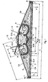
- the luminaire 1 has a quadrangular shape in the viewing direction at right angles to the first radiating region, wherein it is preferably elongated transversely to the plane of the drawing sheet, as it is Fig. 4 shows. It may be a single luminaire or a lamp 1, which is formed at its longitudinal ends for a juxtaposition of multiple lights 1 to a line of light.
- the lamp 1 is preferably a so-called flat lamp, d. h., It is designed in a flat construction of the housing 2, wherein the width b extending transversely to the longitudinal direction is in relation to the height h1, which is about 4: 1 to 8: 1, in particular about 3: 1.
- Lamps 7 may be provided, for. B. in one end region or in both end regions in each case two sockets for two lamps 7, preferably in the form of straight extending tubes, in particular fluorescent tubes.
- the rear wall 2c is formed on both sides of the vertical center plane E2 inclined outwardly, so that the height h1 of the housing 2 tapers to the side or longitudinal sides, preferably to the height h2 of a side profile 11, the edges of the Bottom wall 2a and the rear wall 2c interconnects and forms a low side wall 2b.
- the rear wall 2c at least in the region in which the second light influencing element, which will be described in more detail later, is arranged, is inclined towards the nearest lateral edge of the housing 2.
- the walls of the reinforcing profile 14 are - viewed from the outside - concave, whereby the reinforcing profile 14 is a multi-functional profile, since it not only supporting function and in terms of its interior recording function for ballasts and the like, but its outer surfaces are also used as reflective surfaces , On both sides of the reinforcing profile are accordingly tapering to the side boundary of the lamp towards extending light guide chambers formed.
- the reinforcing profile 14 is closed or closed on the upper side by a profile cover 15, which is preferably detachably connected by a designed as a snap-locking connection quick-release connection with the free edge regions of the profile legs 14 b, z. B. by clipping on.
- a latching connection 16 is provided in each case between the edge regions of the profile limbs 14b and the associated edges of the preferably flat profile cover 15. This can be formed by protruding from the profile legs 14b latching legs 14c, which cooperate latching with the profile cover 15 downwardly projecting locking legs 15a.
- the operating device 8 is preferably arranged in the cavity 17 of the reinforcing profile 14.
- the reinforcing profile 14 preferably extends over the extending transversely to the plane of the drawing length of the lamp 1 and z. B. with end-side End walls of the housing 2 to be connected or supported thereon.
- support webs 18 are provided at longitudinal intervals, which are connected at their upper edges with the rear wall 2c and stabilize them.
- the support webs 18 may extend over the entire width of the interior space, wherein they extend down to the first light-influencing element 9 in the middle region and can support this in the back or on the inside.
- recesses 19 are provided in the support webs, each of which create a lateral longitudinally continuous interior region 5a under the respective lateral areas of the support webs 18.
- the luminaire 1 On the opposite side of the first radiating area 4, the luminaire 1 has at least one second light-emitting area 21 for indirect illumination, which is formed by a translucent or partially transparent section in the rear wall 2c and preferably on the outside - a second light influencing element - described in more detail below 22 is assigned, with which the radiated from the second radiation region 21 light can be influenced or changed, in particular laterally deflected.
- a second light influencing element - described in more detail below 22 is assigned, with which the radiated from the second radiation region 21 light can be influenced or changed, in particular laterally deflected.
- the suspension of the lamp 1 shown is preferably carried out by means of cables cooperating suspension means which may be connected to the end portions of the lamp 1.
- the Abpendel Invention, the Abpendeliere the lamp 1 from the ceiling at least 50 cm, so that the directed against the ceiling indirect light on the ceiling produces no disturbing high and possibly dazzling luminance. However, this does not apply in the case of a smaller, for example, only about 25 cm amount Abpendel ban and of course not if the lamp must be mounted directly in a so-called mounting position below the ceiling,
- the lamp 1 according to the invention is provided with the light influencing elements 22, the indirect light even at a small distance of the lamp 1 to the ceiling wide ensure that the luminance on the ceiling remains within the prescribed range.
- connection elements 6 are arranged for or with a lamp 7 on both sides of the vertical center plane E2
- two second emission regions 21 are each arranged in mirror image with a second light-influencing element 22 with respect to the vertical center axis E2. Therefore, in the following description, the description is limited to a luminaire half, namely the left half of the luminaire.
- the second emission region 21 is located in the rear emission region above the lamp 7 or above the connection means 6, in the region of which the associated lamp 7 is positioned.
- the indirect lighting is favored by the fact that the second emission area 21 is arranged inclined to the associated side edge.
- the angle W2, which the rear wall 2c encloses with the bottom wall 2a, is about 20 to 40 °, in particular about 30 °.
- the second radiating portion 21 is formed by a translucent or partially transparent cover wall 23 which closes an opening 24 corresponding to its shape in the rear wall 2c, in particular by the cover wall 23 being positionable in the opening 24, forming a portion of the rear wall 2c forms.
- the opening 24 is so large that the lamp 7 is movable therethrough and connectable to the one or more connection elements 6 or is removable or interchangeable.
- the at least one connecting element 6 is designed so that the lamp 7 during its insertion and removal movement with its contact elements with associated mating contact elements of the housing 2 during insertion contactable and can be brought out of contact during removal. If z. B. the lamp has 7 end protruding pins, the contact pins receiving contact slots are arranged on the housing side and directed in the direction of movement that the pins are inserted into the slots during insertion of the lamp 7 in the slots and are removable during removal.
- the cover wall 23 is connected by a hinge 25 to the housing 2, which connects the cover wall 23 in the region of its one edge, in particular in the region of its edge facing the vertical center plane E2, with the associated edge region of the housing 2.
- the cover wall 23 is pivotally mounted not only between its closed position and a mounting or dismounting the lamp 7 enabling open position, but it is also held captive on the housing 2.
- cover wall 23 may, for example, on its inner side light-guiding elements 26 for influencing the transmitted light.
- the second radiation region 21 is preferably arranged adjacent to the reinforcement profile.
- the width b1 of the second emission region 21 is approximately one third to one fifth, in particular approximately one fourth, of the dimension b2 of the associated rear wall half. It should be noted, however, that it would also be possible to extend the second radiation area towards the side of the luminaire.
- the cover wall 23 are made transparent or translucent, but also be provided to make the at least partially partially transparent to the cover wall 23 rear wall of the lamp housing.
- the joint 25 is preferably mounted by latching its hinge parts and disassembled by unlocking, in each case by a transversely directed to the hinge axis assembly or disassembly movement.
- the cover wall 23 may, for. B. with two edge-side and inwardly directed legs 23a, 23b U-shaped, wherein the associated hinge part is arranged in the free edge region of the inner wall leg 23a.
- the joint 25 can be realized in a position sunk into the housing 2.
- the wall leg 23b on the outer edge stabilizes and improves the cover wall 23 in the closed position, for. B. by means of a nose 27 in accordance with the sunk in the closed position Fig. 2 and 3 right detent or clamping with the opposite edge of the opening 24 cooperates.
- the joint parts may be formed by an undercut groove with two claw-shaped gutter legs 25c, between which a z. B. in cross-section cylindrical pivot pin 25 b can be latched and disengaged by elastic bending of the gutter legs.
- the hinge 25 may be formed by a plug / rotary socket without latching, with a socket channel, which is open to the free edge of the cover wall 23 and pivoting the cover wall 23 in the inserted position allows without the cover wall side plug-in part Cover wall 23 is latched therein.
- the securing of the cover wall 23 in such a socket channel takes place automatically in the closed position of the cover wall 23 in that the cover wall 23 is delimited by the edge of the opening 24 opposite the socket channel in the socket channel.
- the second light-influencing element 22 is formed by a light distribution wing in the form of a thin wall part, which is detachably connected to the housing 2 by a quick-connection 31 in the region of the rear wall 2c.
- the quick-release connection 31 is in the region of the joint 25 and the jack, z. B. sunk in part in the outer surface of the rear wall 2c and / or offset inwardly by the offset v.
- the second light-influencing element 22 is adjustable in at least two different positions, can be pivoted to be exact, with the quick-release connection 31 located on the carrier hollow profile or the reinforcing profile 14 permitting this.
- Two possible positions for the second light-influencing element 22 are denoted by S1 and S2.
- S1 the so-called light distribution position
- the second light-influencing element 22 projects transversely to the rear wall 2c, namely upwards in the case of a ceiling light.
- the Abklappposition is the second light influencing element 22 in a moved against the rear wall 2c position, wherein it preferably rests against the cover wall 23 and the cover wall 23 and the opening 24 completely or partially or almost covers.
- the width b3 of the light-influencing element 22 is so great that its free edge ends at a distance c in front of the outer edge of the second light-emitting region 21 or the opening 24.
- the distance c is z. B. about 1 ⁇ 4 of b1.
- the directed in the position S1 to the associated side wall surface 22a is preferably curved about a parallel to the center plane E2 extending axis of curvature, preferably curved cylindrical section or rounded.
- the second light-influencing element 22 can influence the light emitted by the second emission region 21, in particular the light emitted in the region of the second emission region 21 facing the center plane E2, and thereby to change the indirect illumination.
- the second light-influencing element 22 can be at least partially translucent or form a reflector 32, which reflects the light radiated from the second emission region 21 toward the side facing away from the center plane E2.
- the reflector 32 may, for. B. be formed in that the second radiation area 21 facing wall surface 23a is a reflection surface.
- the second light influencing element 22 includes an acute angle W2 with the center plane E2, which may be less than about 40 °.
- the second light-influencing element 22 serves to cover the opening 24 or the second light-emitting region 21 completely or partially or almost completely, thereby at least partially shading the light.
- the second light-influencing element 22 is designed as a reflector 32, the light is reflected in the covered area, so that virtually no light losses occur in this area.
- This second position S2 is used for. B. to avoid the indirect lighting or reduce.
- This arrangement of the second light influencing element 22 will therefore be chosen especially if the luminaire is directly under the ceiling, i. must be mounted in a so-called mounting position.
- the light-influencing element 22 is located directly above or adjacent to the translucent cover 23, so that the light is faded upwards and the light component striking the light-influencing element 22 is reflected downwards for amplifying the direct light Folded outward Light influencing element 22 thus ensures, by the achieved dimming effect, that the luminance on the ceiling always remains within the permissible range.
- the second light-influencing element 22 is also preferably adjustable to a third position S3 in which it is moved inwardly and against the housing 2, wherein it may be located at the top of the housing 2 and may rest on the rear wall 2c or on the profile cover 15 , In this position S3, the second light influencing element 22 is in a non-lighting inoperative position or parking position, the z. B. may also be a packaging or transport position. If both light influencing elements 22 are present, they may overlap and lie on top of each other as it does Fig. 1 and 2 demonstrate.
- the quick-release connection 31 as pivoting hinge or hinge 33 such that the second light influencing element 22 can be pivoted between its positions S1 and S2.
- the light influencing element 22 is detectable in optional pivot positions, z. B. by stiffness in the quick connection, can be realized either swivel positions and light influencing positions.
- Another way to adjust the second light influencing element 22 from the position S2 to the S3 position or vice versa is to release the light influencing element 22 and rotate approximately parallel to the rear wall or an imaginary plane running on the rear wall by 180 ° and in the Quick connect 31 again to connect.
- the quick-release connection 31 by a clamping or latching connector, z. B. to realize a locking connection or a plug / pivot connection, as shown in the embodiments.
- the latching connection is formed by a latching pin 31a, preferably of rounded cross-section, and two latching claws 31b, which can be elastically latched onto it.
- the latching pin 31a is arranged via a web on the reinforcing profile 14, preferably on its cover 15, in an upwardly open, part-cylindrical channel and the latching claws 31b are arranged on the associated edge of the light influencing element 22.
- the latching takes place in that the latching claws 31b resiliently rebound when plugged in and slightly engage behind the latching pin 31a in the plugged state, whereby they automatically deflect.
- the locking pin 31a is firmly connected by a small connecting web 31c with its carrier.
- the circumferentially directed distance between the detent pawls 31b is so large considering the small width of the connecting web 31c, in that the light-influencing element 22 is pivotable between the position S1 and the position S3.
- the arrangement is preferably such that in the reflective position S1 the light influencing element 22 is made more difficult or limited against pivoting towards the cover element 23, namely by a stop position between the associated connection claw 31b and the connecting web 31c.
- the wall of the light-influencing element 22 consists of two wall sections enclosing an obtuse angle W3, the apex 22a of which is located approximately above the inner edge of the second light-emitting area 21.
- the inner region of the light-influencing element 22 serves in this case to receive the latching claws 31b, while the outer region serves as a reflector or scattering surface and may be, for example, anodized matt.
- the latching connection or the integrated joint 33 is located in the edge or corner region of the lid 15.
- the hinge 25 for the cover wall 23 is formed in the embodiment between the upper edge region of the associated profile leg 14b and a lid 15 obliquely outwardly and upwardly extending legs 15b, which also forms the associated gutter leg 25c. As a result, the joint 25 between the associated profile leg 14b and the lid 15 is arranged.
- the second light-emitting region 21 and the cover element 23 and the second light-influencing element 22 preferably extend over the dimension or length L of the housing 2 extending transversely to the plane of the drawing. This also applies in the case of an elongated design of the luminaire 1 according to FIG Fig. 4 ,
- the second light-influencing element 22 and the cover element 23 and the associated hinge parts in this case the latching pin 31a and the latching claws 31b and the channel legs 25c, preferably extend continuously and straightly transversely to the plane of the drawing sheet.
- These parts can thus be produced inexpensively as profile parts, for example by drawing or extruding one long semi-finished product and by cutting to length.
- Fig. 8 shows an embodiment of the lamp 1 according to the invention, which in turn is intended for low Abpendelenburgn, in which case the inner region of the light influencing elements 22 is selected over a large area to increase the direct light component by reflection of the light at this correspondingly formed inner region.
- the inner region of the light influencing elements 22 is selected over a large area to increase the direct light component by reflection of the light at this correspondingly formed inner region.
- a lamp 1 according to the invention is particularly for large room heights, ie determined correspondingly larger Abpendel Eckn.
- Characteristic of this embodiment is that the light influencing elements 22 are designed to have a larger area and extend into the areas above the light guiding chambers, wherein it is provided in the example shown that the light influencing elements 22 extend into the edge region of the luminaire 1.
- the interior of the light influencing elements 22 may be made by selecting the offset 24, i.e., the distance between the pivot bearing and the outside as a partial cover with respect to the lamps, to reduce the luminance on the outside reflective area of the light influencing elements 22 and to maximize the direct light portion by internal reflection.
- the light-influencing elements 22 can be designed to be both reflective and scattering, and in particular also transparent or semitransparent, so that the light generation and light distribution required in the respective individual case can be ensured.
- these second light-influencing elements 22 and / or the cover wall 23 (perforated plate) and / or the reinforcing profile 14 and / or the lid 15 may be made of metal or plastic.
- the possible uses of interior lights or pendant lights are significantly expanded. It is achieved in particular that regardless of the size of the distance between the luminaire and the ceiling, optimum distribution ratios between direct light and indirect light, which take account of the respective demands, can always be obtained. Due to the different embodiments of the light distribution wings or second light influencing elements and a more or less large extension of the concave reflection or scattering surfaces outside the closed luminaire structure, the light distribution can be optimally realized and all requirements for the respective installation conditions in different heights rooms can be met. All this can be achieved with very little effort. In particular, it can even be decided on-site when assembling which type of light distribution vanes are used in order to optimally ensure the locally required light distributions.
Abstract
Description
Die Erfindung betrifft eine Leuchte gemäß dem Oberbegriff des Anspruchs 1.The invention relates to a luminaire according to the preamble of
Bei einer Leuchte dieser Art handelt es sich um bekannte Konstruktionen, die insbesondere als Hängeleuchte vorbekannt sind. Wesentliches Merkmal dieser Leuchte ist, dass sie an einer Seite ihres Gehäuses einen ersten Licht-Abstrahlbereich zur direkten Beleuchtung des Raumes und einen zweiten Licht-Abstrahlbereich aufweist, der zur indirekten Beleuchtung des Raumes dient und an der dem ersten Licht-Abstrahlbereich gegenüberliegenden Rückseite der Leuchte angeordnet ist. Es ist der Zweck des ein lichtdurchlässiges Lichtbeeinflussungselement aufweisenden zweiten Licht-Abstrahlbereichs, die seitliche und/oder rückseitige Umgebung der Leuchte zu erhellen, um den Lichtstärkenunterschied zwischen dem ersten Licht-Abstrahlbereich und der Umgebung der Leuchte zu vermindern und/oder zusätzlich zur direkten Beleuchtung eine indirekte Beleuchtung insbesondere an der Rückseite der Leuchte herbeizuführen, was die Raumbeleuchtung verbessert und Helligkeitsunterschiede im rückseitigen und seitlichen Bereich der Leuchte vermindert. Eine derartige Leuchte ist beispielsweise in der
Bei dem lichtdurchlässigen Lichtbeeinflussungselement des zweiten Licht-Abstrahlbereichs kann es sich z. B. um ein Element handeln, das lichtdurchlässig oder teillichtdurchlässig ist und durch eine lichtdurchlässige Scheibe oder ein Lochblech gebildet ist, das z. B. im Bereich der Rückwand des Gehäuses der Leuchte angeordnet ist.In the light-transmissive light influencing element of the second light-emitting region, it may, for. B. to act an element that is translucent or teillichtdurchlässig and is formed by a translucent disc or a perforated plate, the z. B. is arranged in the region of the rear wall of the housing of the lamp.
Leuchten der vorbeschriebenen Art werden im Regelfall in einem Abstand zur Decke von mindestens 50 cm aufgehängt. Derartige Abpendelhöhen gewährleisten deckenseitig eine als angenehm empfundene, blendfreie Leuchtdichte. In bestimmten Anwendungsfällen allerdings müssen die Leuchten entweder mit einem geringen Abstand zur Decke oder bei großen Raumhöhen auch mit ungewöhnlich großem Abstand zur Decke montiert werden, was dazu führen kann, dass zum einen deckenseitig unerwünscht hohe Leuchtdichten auftreten, die einer entsprechenden Montage entgegenstehen und demgemäß die Einsatzmöglichkeiten der Leuchte beschränken könnten, oder andererseits bei großer Abpendelhöhe deckenseitig zu niedrige Leuchtdichten auftreten und der im Raum erwünschte Anteil an indirektem Licht zu gering wird.Lights of the type described above are usually suspended at a distance from the ceiling of at least 50 cm. Such Abpendelhöhen ensure the ceiling side as pleasant perceived, glare-free luminance. In certain applications, however, the lights must be mounted either with a small distance to the ceiling or at high ceiling heights with an unusually large distance to the ceiling, which can lead to the one side undesirable high luminance occur that oppose a corresponding assembly and accordingly the Possible applications of the luminaire could limit, or on the other hand, with large Abpendelhöhe ceiling side Low luminance occur and the desired in the room share of indirect light is too low.
Aus der
Aus der
Aus der
Der Erfindung liegt deshalb die Aufgabe zugrunde, eine Leuchte der eingangs angegebenen Art bezüglich der Indirektbeleuchtung zu verbessern. Es soll insbesondere das für die Indirektbeleuchtung abgestrahlte Licht besser ausgenutzt werden, vorzugsweise für die seitlichen Randbereiche der Leuchte. Dabei soll die Leuchte unter Gewährleistung optimaler Lichtverteilungen sowohl hinsichtlich des direkten als auch des indirekten Lichts sowohl mit geringen Abpendelhöhen und unmittelbar unter der Decke, d.h. in einer so genannten Anbauposition, als auch bei entsprechenden Raumhöhen mit großen Abpendelhöhen montiert werden können.The invention is therefore based on the object to improve a luminaire of the type specified with respect to the indirect lighting. In particular, the light emitted for the indirect illumination should be better utilized, preferably for the lateral edge regions of the luminaire. In this case, the lamp is to ensure optimal light distribution both in terms of direct and indirect light with low Abpendelhöhen and immediately under the ceiling, i. can be mounted in a so-called mounting position, as well as at corresponding room heights with large Abpendelhöhen.
Diese Aufgabe wird durch die Merkmale des Anspruchs 1 gelöst. Vorteilhafte Weiterbildungen der Erfindung sind in den zugehörigen Unteransprüchen beschrieben.This object is solved by the features of
Der Erfindung liegt die Erkenntnis zugrunde, dass eine Indirektbeleuchtung insbesondere im seitlichen Randbereich der Leuchte bedeutungsvoll ist, da eine mangelnde Indirektbeleuchtung im wesentlichen zu Helligkeitsunterschieden, insbesondere im Randbereich der Leuchte führt.The invention is based on the finding that an indirect illumination, in particular in the lateral edge region of the luminaire, is meaningful, since a lack of indirect illumination essentially leads to brightness differences, in particular in the edge region of the luminaire.
Bei der erfindungsgemäßen Leuchte ist ein dem zweiten Abstrahlbereich zugeordnetes zweites Lichtbeeinflussungselement in wenigstens zwei unterschiedliche Stellungen verstellbar. Hierdurch ist es möglich, das zweite Lichtbeeinflussungselement an gezielte Beeinflussungen oder auch eine Nichtbeeinflussung des Lichts der Indirektbeleuchtung anzupassen. Als zweites Lichtbeeinflussungselement kann beispielsweise deckenseitig an der Leuchte bzw. einem entsprechenden Trägerprofil ein schwenk- und/oder lösbar gelagerter Lichtverteilungsflügel vorgesehen sein, dessen Form und/oder Größe sowie dessen Position und/oder Neigung relativ zur vertikalen Mittelebene der Leuchte insbesondere in Abhängigkeit vom jeweiligen Abstand der Leuchte zur Decke wählbar ist. Das zweite Lichtbeeinflussungselement kann also beispielsweise so verstellt werden, dass es zur Begrenzung der Öffnung für das Licht der Indirektbeleuchtung dienen kann, um je nach Stellung eine kleinere oder größere Öffnung zu begrenzen, oder die Öffnung vollständig freizugeben.In the luminaire according to the invention, a second light-influencing element assigned to the second emission region can be adjusted into at least two different positions. As a result, it is possible to adapt the second light-influencing element to targeted influencing or also a non-influencing of the light of the indirect lighting. As a second light-influencing element, a pivotally and / or releasably mounted light distribution wing can be provided, for example, on the ceiling side of the luminaire or a corresponding carrier profile. whose shape and / or size as well as its position and / or inclination relative to the vertical center plane of the lamp in particular in dependence on the respective distance of the lamp to the ceiling is selectable. The second light-influencing element can thus be adjusted, for example, so that it can serve to limit the opening for the light of the indirect lighting, depending on the position to limit a smaller or larger opening, or to fully release the opening.
Insbesondere dann, wenn das zweite Lichtbeeinflussungselement ein Reflektor ist, lässt sich das indirekte Licht seitlich zur verstärkten Beleuchtung des Seitenrandbereichs der Leuchte reflektieren und umlenken. In diesem Fall werden zusätzlich zu den leuchtenseitig ggf. bereits vorhandenen Reflexionsflächen zusätzliche Reflexionsflächen und gegebenenfalls auch Abblendflächen bereitgestellt, die zu spezifischen Anpassungsmöglichkeiten an unterschiedliche Raumhöhen bzw. Abpendelhöhen führen.In particular, when the second light-influencing element is a reflector, the indirect light can be laterally reflected and deflected to the reinforced illumination of the side edge region of the luminaire. In this case, in addition to the reflection side possibly already existing on the luminaire side, additional reflection surfaces and, if appropriate, also dimming surfaces are provided, which lead to specific adaptation options to different room heights or Abpendelhöhen.
Bei niedrigen Räumen und entsprechend geringen Abpendelhöhen, die bis zur direkten Anbausituationen gehen können, werden die Lichtverteilungsflügel beispielsweise derart gestaltet und dimensioniert, dass unzulässig hohe Leuchtdichten an der Decke vermieden werden und eine großflächige Deckenaufhellung und damit Direktlichterzeugung erfolgt. Bei sehr großen Abpendelhöhen hingegen, bei denen die Leuchtdichte an der Decke zu gering wird und eine ungenügende Erzeugung von indirektem Licht vorliegen kann, werden die Lichtverteilungsflügel vorzugsweise großflächiger gestaltet und dazu genutzt, das erwünschte, weiche indirekte Licht in den Raum abzustrahlen, das in diesem Falle nicht über eine Reflexion an der Decke in ausreichendem Maße geliefert werden kann.With low rooms and correspondingly low Abpendelhöhen that can go up to direct mounting situations, the light distribution wings are, for example, designed and dimensioned so that unacceptably high luminances are avoided on the ceiling and a large-area ceiling illumination and thus direct light generation occurs. By contrast, in the case of very large pendulum heights, where the luminance on the ceiling becomes too low and there is insufficient generation of indirect light, the light distribution vanes are preferably made larger and used to radiate the desired, soft, indirect light into the space that is there Trap can not be delivered over a reflection on the ceiling sufficiently.
Da der als zweites Lichtbeeinflussungselement dienende Lichtverteilungsflügel reflektierend, transparent und/oder teil-transparent ausgebildet sein kann, ist es möglich, unter Berücksichtigung der weitgehend frei wählbaren Flügelformen und Flügelgrößen sehr unterschiedliche Lichtverteilungen zwischen direktem und indirektem Licht in Abhängigkeit vom jeweiligen Einsatzgebiet der Leuchten zu erzielen.Since the light distribution vane serving as the second light-influencing element can be reflective, transparent and / or partially transparent, it is possible to achieve very different light distributions between direct and indirect light as a function of the respective field of use of the luminaires, taking into account the largely freely selectable vane shapes and vane sizes ,
Eine vorteilhafte Weiterbildung der Erfindung kann darin bestehen, dass nicht nur das zweite Lichtbeeinflussungselement schwenkbar, insbesondere in eine Parkstellung verschwenkbar ausgebildet ist, sondern dass in analoger Weise auch eine sich oberhalb einer in dem Leuchtengehäuse angeordneten Leuchtstofflampe befindende lichtdurchlässige Abdeckung entsprechend verschwenkbar bzw. hoch-schwenkbar ausgestaltet sein kann und damit die Lampe für einen eventuell erforderlichen Lampenwechsel bequem zugänglich ist.An advantageous development of the invention may consist in that not only the second light influencing element is pivotable, in particular pivotable in a parking position, but that in an analogous manner also located above a arranged in the lamp housing fluorescent lamp translucent cover according to pivotable or high-swivel can be configured and thus the lamp for any required lamp replacement is easily accessible.
Bevorzugt ist das zweite Lichtbeeinflussungselement an einem Abdeckprofil schwenkbar gelagert, das mit einem deckenseitig offenen Verstärkungsprofil bzw. Trägerhohlprofil insbesondere über eine Schnapp-Rastverbindung kuppelbar ist. Die Nutzung des Abdeckprofils zur Lagerung des zweiten Lichtbeeinflussungselements führt zum einen zu einer technisch überaus einfachen, grundsätzlich auch nachrüstbaren Lösung und gestattet andererseits eine durch einen einfachen Schwenkvorgang durchführbare Überführung des zweiten Lichtbeeinflussungselements aus einer lichttechnisch unwirksamen Parkposition oberhalb des Abdeckprofils in eine Funktionsstellung, in der es von der in der Leuchte befindlichen Lichtquelle oder entsprechenden reflektierenden Flächen kommendes Licht durch Reflexions- und/oder Streueffekte großflächig über die Decke verteilt. Bei dieser Ausführungsform ist das zweite Lichtbeeinflussungselement vorzugsweise vergleichsweise kleinflächig gestaltet, d.h., seine Fläche entspricht im Wesentlichen einer ihr benachbarten trägerprofilseitigen Reflexionsfläche, ohne auf dieses Größenverhältnis der Reflexionsflächen beschränkt zu sein.Preferably, the second light-influencing element is pivotally mounted on a cover, which can be coupled with a cover profile open or reinforcing hollow profile, in particular via a snap-locking connection. The use of the cover for supporting the second light influencing element leads to a technically very simple, basically retrofittable solution and on the other hand allows a feasible by a simple pivoting transfer of the second light influencing element from a photovoltaic inoperative parking position above the cover into a functional position in which it from the light source or corresponding reflective surfaces in the luminaire Light distributed over the ceiling over large areas due to reflection and / or scattering effects. In this embodiment, the second light-influencing element is preferably made comparatively small area, ie, its surface substantially corresponds to a carrier profile-side reflecting surface adjacent to it, without being limited to this size ratio of the reflection surfaces.
Für den Fall großer Abpendelhöhen in entsprechend hohen Räumen hingegen weist das zweite Lichtbeeinflussungselement bevorzugt einen großflächigen konkaven Außenbereich auf, der in Ergänzung der zugehörigen Reflexionsfläche des Verstärkungsprofils bzw. Trägerhohlprofils sowohl zur Direktlichterzeugung beiträgt als auch dazu dient, den erwünschten indirekten Lichtanteil bereitzustellen, der in diesem Fall wegen der großen Abpendelhöhe nicht durch Streueffekte an der Decke bereitgestellt werden kann.In the case of large Abpendelhöhen in correspondingly high rooms, however, the second light influencing element preferably has a large concave outer area, which contributes to the addition of the associated reflection surface of the reinforcing profile or carrier hollow profile both for direct light generation and serves to provide the desired indirect light component in this Case can not be provided by scattering effects on the ceiling because of the large Abpendelhöhe.
Eine vorteilhafte Weiterbildung zeichnet sich ferner dadurch aus, dass das. Abdeckprofil randseitig jeweils eine teilzylindrische, nach oben offene Rinne mit einem zur Rinne konzentrischen, über einen Steg mit dem Rinnenboden verbundenen zylindrischen Profilstab aufweist, dass der lagerseitige Rand des zweiten Lichtbeeinflussungselements als teilzylindrisches Kupplungselement ausgebildet ist, und dass im zusammengefügten Zustand die teilzylindrische Rinne mit zur Rinne konzentrischem Profilstab und das formschlüssig in den Aufnahmebereich zwischen Rinne und Profilstab eingreifende Kupplungselement ein Schwenkscharnier bilden. Die Öffnung der teilzylindrischen Rinne ist dabei derart auf das teilzylindrische Kupplungselement des zweiten Lichtbeeinflussungselements abgestimmt, dass das zweite Lichtbeeinflussungselement senkrecht zur Längserstreckung der Aufnahmerinne in diese Rinne einführbar ist und dann durch Verschwenken des zweiten Lichtbeeinflussungselements aus der Einführposition die eigentliche Scharnierbildung zwangsläufig erfolgt. Ein Entkoppeln zwischen zweitem Lichtbeeinflussungselement und Abdeckprofil ist wiederum auf entsprechend einfache Weise möglich, da dazu das Lichtbeeinflussungselement lediglich in die vorstehend geschilderte Einführposition zurückgeschwenkt werden muss und dann vom Abdeckprofil gelöst werden kann.An advantageous development is further characterized by the fact that the cover profile at the edge each has a part-cylindrical, upwardly open channel with a concentric to the channel, connected via a web to the channel bottom cylindrical profile bar, that the bearing-side edge of the second light influencing element formed as a part-cylindrical coupling element is, and that in the assembled state, the part-cylindrical groove with the channel concentric profile bar and the form-fitting engaging in the receiving area between the channel and profile bar coupling element form a pivoting hinge. The opening of the partially cylindrical channel is matched to the partially cylindrical coupling element of the second light influencing element such that the second light influencing element is inserted perpendicular to the longitudinal extent of the receiving channel in this groove and then by pivoting the second light influencing element from the insertion position, the actual hinge formation is inevitable. Decoupling between the second light-influencing element and covering profile is again possible in a correspondingly simple manner, since the light-influencing element only has to be pivoted back into the above-described insertion position and then released from the covering profile.
Diese einfache Kuppel- und Lösbarkeit des zweiten Lichtbeeinflussungselements ist auch im Zusammenhang mit einer weiteren Besonderheit der Erfindung von Vorteil, nämlich der Möglichkeit, das Lichtbeeinflussungselement um 180° versetzt in die Aufnahmerinne des Abdeckprofils einstecken zu können, denn bei dieser Montageart ist das Lichtbeeinflussungselement nach außen abklappbar und liegt dabei beispielsweise auf der oberen lichtdurchlässigen Abdeckung für die Lichtquelle auf.This simple coupling and releasability of the second light-influencing element is also advantageous in connection with another feature of the invention, namely the possibility of inserting the light-influencing element offset by 180 ° in the receiving channel of the cover profile, because in this type of mounting, the light-influencing element to the outside hinged and lies, for example, on the upper translucent cover for the light source.
Dies hat zur Folge, dass ein wählbarer Teil dieser licht-durchlässigen Lampenabdeckung nach oben abgeblendet wird und das auf diesen Teil der Abdeckung treffende Licht durch das zweite Lichtbeeinflussungselement zur Verstärkung des direkten Lichts nach unten reflektiert wird. Damit kann sichergestellt werden, dass die Leuchtdichte an der Decke direkt über den Lampen stets im zulässigen Bereich bleibt.As a result, a selectable part of this light-transmissive lamp cover is dimmed up and the light incident on that part of the cover is reflected downwardly by the second light influencing element for amplifying the direct light. This ensures that the luminance on the ceiling directly above the lamps always remains within the permissible range.
Ein weiterer noch speziell zu erwähnender Vorteil der Erfindung besteht darin, dass das bevorzugt aus einem wärmeleitenden Material bestehende zweite Lichtbeeinflussungselement, das mit dem Trägerhohlprofil wärmeleitend gekoppelt ist, in allen seinen Betriebsstellungen wirksame Kühlflächen bildet.Another particular advantage of the invention to be mentioned is that the preferably consisting of a thermally conductive material second light influencing element, which is thermally conductively coupled to the carrier hollow profile, forms effective cooling surfaces in all its operating positions.
Die erfindungsgemäße Ausgestaltung eignet sich für alle solchen Leuchten, deren Seitenrand ein quer zur Abstrahlseite der Leuchte gerichteten Abstand von seinem Träger aufweist, insbesondere einer Raumdecke. Deshalb eignet sich die Erfindung vorzüglich für eine Hängeleuchte. Die Erfindung eignet sich aber auch für eine Anbauleuchte, insbesondere dann, wenn die Rückwand der Leuchte zum Seitenrand hin geneigt ist.The embodiment of the invention is suitable for all such lights whose side edge has a transversely directed to the emission side of the lamp distance from its support, in particular a ceiling. Therefore, the invention is excellent for a suspension lamp. However, the invention is also suitable for a surface-mounted luminaire, in particular when the rear wall of the luminaire is inclined to the side edge.
Die oben genannte Aufgabe wird ferner auch durch die Merkmale des unabhängigen Anspruchs 27 gelöst. Bei dieser erfindungsgemäßen Ausgestaltung ist das Gehäuse ein Flachgehäuse, wobei die zweiten Abstrahlbereiche an der Rückseite des Flachgehäuses angeordnet sind und die Schnellschlussverbindungen im Bereich der inneren Ränder der zweiten Abstrahlbereiche angeordnet sind. Diese erfindungsgemäße Ausgestaltung führt zu einer Leuchte in Flachbauweise, bei der die Indirektbeleuchtung wegen der niedrigen Konstruktionshöhe schwierig ist. Die erfindungsgemäßen Ausgestaltungen ermöglichen jedoch auch bei einer solchen Leuchtenkonstruktion die angestrebte Verbesserung der Indirektbeleuchtung, insbesondere in den einander gegenüberliegenden Seitenrandbereichen der Leuchte. Außerdem lassen sich bei dieser Leuchte die zweiten Lichtbeeinflussungselemente handhabungsfreundlich montieren und demontieren und somit die Leuchte wahlweise an eine Indirektbeleuchtung anpassen.The above object is further solved by the features of
Gemäß dem dritten unabhängigen Anspruch 28 schließlich wird eine Leuchte, insbesondere eine Innenraumleuchte oder Hängeleuchte in Flachbauweise vorgeschlagen, welche raum- und/oder deckenseitig gelegene Lichtaustrittsflächen, ein mittig und zwischen zwei Endteilen angeordnetes, eine hohe Durchbiegesteifigkeit aufweisendes Trägerhohlprofil mit innen liegendem Aufnahmeraum und außen liegenden konkaven Reflexionsflächen für zumindest zwei zum Trägerhohlprofil benachbart und dazu parallel verlaufende Leuchtstofflampen, sowie beiderseits des Trägerhohlprofils und seitlich der Leuchtstofflampen vorgesehene, sich verjüngend bis zur Seitenbegrenzung der Leuchte erstreckende und durch zumindest raumseitige Lichtaustrittsflächen geschlossene Lichtführungskammern aufweist, wobei deckenseitig am Trägerhohlprofil schwenk- und/oder lösbar gelagerte Lichtbeeinflussungselemente in Form von Lichtverteilungsflügeln vorgesehen sind, deren Form und/oder Größe sowie deren Position und/oder Neigung relativ zur vertikalen Mittelebene des Trägerhohlprofils insbesondere in Abhängigkeit vom jeweiligen Abstand der Leuchte zur Decke wählbar ist.Finally, according to the third independent claim 28, a luminaire, in particular an interior luminaire or suspended luminaire in a flat construction, is proposed, which light and outlet surfaces located on the ceiling, a center and between two end portions arranged, a high flexural stiffness exhibiting carrier hollow profile with internal receiving space and outside concave reflecting surfaces for at least two to the carrier hollow profile adjacent and parallel fluorescent lamps, as well as on both sides of the carrier hollow profile and the side of the fluorescent lamps provided, tapering to the side of the light and extending through at least room-side light exit surfaces closed Lichtführungskammern having ceiling on the carrier hollow profile pivotally and / or releasably mounted light influencing elements in the form of Lichtverteilungsflügeln are provided, whose shape and / or size and their position and / or inclination relative to the vertical center plane of the carrier hollow profile, in particular depending on the respective distance of the lamp to the ceiling is selectable.
In den Unteransprüchen sind Merkmale enthalten, die einfache, kleine und kostengünstig herstellbare Konstruktionen ermöglichen und sich insbesondere für eine längliche Leuchte eignen.In the subclaims features are included that allow simple, small and inexpensive to produce constructions and are particularly suitable for an elongated lamp.
Nachfolgend werden vorteilhafte Ausgestaltungen der Erfindung anhand von bevorzugten Ausführungsbeispielen und Zeichnungen näher erläutert. Es zeigen:
-
Fig. 1 eine erfindungsgemäße Leuchte im vertikalen Querschnitt; -
Fig. 2 den oberen und mittleren Teilbereich der Leuchte in vergrößerter Darstellung; -
Fig. 3 den Teilbereich in einer besonderen Funktionsstellung; -
Fig. 4 die Leuchte in perspektivischer Seitenansicht von oben; -
Fig. 5 bis 7 die zweiten Lichtbeeinflussungselemente in drei verschiedenen Positionen und -
Fig. 8 und 9 zwei weitere Ausführungsbeispiele der erfindungsgemäßen Leuchte im Schnitt.
-
Fig. 1 a luminaire according to the invention in vertical cross-section; -
Fig. 2 the upper and middle portion of the lamp in an enlarged view; -
Fig. 3 the subarea in a special functional position; -
Fig. 4 the lamp in a perspective side view from above; -
Fig. 5 to 7 the second light influencing elements in three different positions and -
8 and 9 two further embodiments of the lamp according to the invention in section.
Die Hauptteile der in ihrer Gesamtheit mit 1 bezeichneten Leuchte sind ein Gehäuse 2, das an seiner Abstrahlseite, nämlich an seiner dem zu beleuchtenden Raum 3 zugewandten Seite, einen ersten Licht-Abstrahlbereich 4 aufweist, der sich beim vorliegenden Ausführungsbeispiel der Leuchte 1 im wesentlichen über die gesamte dem Raum 3 zugewandten Seite des Gehäuses 2 erstreckt und sich dabei vorzugsweise in einer Abstrahlebene E1 erstreckt.The main parts of the designated in their entirety by 1 luminaire are a
Das Gehäuse 2 umschließt mit seiner abstrahlseitigen lichtdurchlässigen Bodenwand 2a, einander gegenüberliegenden Seitenwänden 2b und einer dem ersten Abstrahlbereich 4 gegenüberliegenden Rückwand 2c einen Gehäuse-Innenraum 5 ein, in dem wenigstens ein Anschlussmittel 6 für wenigstens eine Lampe 7 angeordnet und z. B. an einer Gehäuse-Innenwand befestigt ist, die durch nicht dargestellte elektrische Leitungen mit einer elektrischen Stromversorgung verbunden ist. Die Lampe 7 kann z. B. eine so genannte Leuchtstofflampe sein, zu deren Stromversorgung ein Betriebsgerät 8 gehört, das z. B. ebenfalls zwischen der Bodenwand 2a und der Rückwand 2c im Innenraum 5 angeordnet sein kann.The
Im sich vorzugsweise etwa über die gesamte Abstrahlseite des Gehäuses 2 erstreckenden Abstrahlbereich 4 ist ein erstes Lichtbeeinflussungselement 9 angeordnet, das die Bodenwand 2a bildet, vorzugsweise eben ausgebildet ist und insbesondere entblendet ist, so dass die maximale Größe eines von der sich rechtwinklig zur Abstrahlebene E1 erstreckenden Hauptabstrahlrichtung R abweichenden seitlichen Abstrahlwinkels W1 auf ein Winkelmaß begrenzt ist, das bezüglich einer im beleuchteten Raum 3 stehenden und schräg aufwärts blickenden Person eine hinreichende Entblendung ergibt. Dies lässt sich durch eine an sich bekannte Entblendungsstruktur erreichen, die am ersten Lichtbeeinflussungselement 9 außenseitig oder innenseitig angeordnet ist oder zwischen zwei aufeinanderliegenden und das erste Lichtbeeinflussungselement 9 bildenden Scheiben angeordnet ist. Dabei kann die Entblendungsstruktur an der zugehörigen Seite des betreffenden Lichtbeeinflussungselements bzw. der Scheibe oder an einer transparenten Folie ausgebildet sein, die innen oder außen oder zwischen den vorgenannten scheibenförmigen Elementen angeordnet sein kann.In the preferably approximately over the entire emission side of the
Die Leuchte 1 weist in der Blickrichtung rechtwinklig zum ersten Abstrahlbereich eine viereckige Form auf, wobei sie quer zur Zeichnungsblattebene vorzugsweise länglich ausgebildet ist, wie es
Die Leuchte 1 ist vorzugsweise eine so genannte Flachleuchte, d. h., sie ist in Flachbauweise des Gehäuses 2 konzipiert, wobei die sich quer zur Längsrichtung erstreckende Breite b in einem Verhältnis zur Höhe h1 steht, das etwa 4:1 bis 8:1, insbesondere etwa 3:1 beträgt.The
Insbesondere bei einer Leuchte 1 länglicher Konstruktion können auf beiden Seiten ihrer vertikalen Mittelebene bzw. Längsmittelebene E2 Anschlussmittel 6 für zwei Lampen 7 vorgesehen sein, z. B. im einen Endbereich oder in beiden Endbereichen jeweils zwei Fassungen für zwei Lampen 7, vorzugsweise in der Form von sich gerade erstreckenden Röhren, insbesondere Leuchtstoffröhren.In particular, in a
Beim Ausführungsbeispiel ist die Rückwand 2c auf beiden Seiten der vertikalen Mittelebene E2 nach außen geneigt ausgebildet, so dass die Höhe h1 des Gehäuses 2 sich zu den Seiten- bzw. Längsseiten hin verjüngt, vorzugsweise auf die Höhe h2 eines Seitenprofils 11, das die Ränder der Bodenwand 2a und der Rückwand 2c miteinander verbindet und eine niedrige Seitenwand 2b bildet. Insbesondere ist die Rückwand 2c wenigstens in dem Bereich, in dem das später noch näher beschriebene zweite Lichtbeeinflussungselement angeordnet ist, zum am nächsten liegenden seitlichen Rand des Gehäuses 2 hin geneigt.In the embodiment, the
Zunächst wird ein bezüglich der vertikalen Längsmittelebene E2 mittig bzw. zentral zwischen den beiden Lampen 7 angeordnetes Verstärkungsprofil 14 in Form eines Trägerhohlprofils beschrieben, das im wesentlichen eine V- bzw. U-förmige Querschnittsform aufweist und in einer solchen Position in das Gehäuse 2 integriert ist, dass sein Bodensteg 14a einen vertikalen Abstand vom vorzugsweise ebenen bzw. plattenförmigen ersten Lichtbeeinflussungselement 9 aufweist und seine seitlichen Profilschenkel 14b sich bis in den oberen Bereich des Gehäuses 2 erstrecken, z. B. einen vertikalen Abstand von der Oberseite des Gehäuses 2 aufweisen. Die Wandungen des Verstärkungsprofils 14 sind - von außen betrachtet - konkav ausgebildet, wodurch das Verstärkungsprofil 14 zu einem Multifunktionsprofil wird, da es nicht nur tragende Funktion und im Hinblick auf seinen Innenraum Aufnahmefunktion für Vorschaltgeräte und dergleichen besitzt, sondern seine Außenflächen gleichzeitig als Reflexionsflächen genutzt sind. Zu beiden Seiten des Verstärkungsprofils sind dementsprechend sich verjüngend bis zur Seitenbegrenzung der Leuchte hin erstreckende Lichtführungskammern gebildet.First, with respect to the vertical longitudinal center plane E2 centrally or centrally between the two
Das Verstärkungsprofil 14 ist oberseitig durch einen Profildeckel 15 verschließbar bzw. verschlossen, der vorzugsweise durch eine als Schnapp-Rastverbindung ausgeführte Schnellschlussverbindung mit dem freien Randbereichen der Profilschenkel 14b lösbar verbunden ist, z. B. durch Aufklipsen. Hierzu ist zwischen den Randbereichen der Profilschenkel 14b und den zugehörigen Rändern des vorzugsweise flachen Profildeckels 15 jeweils eine Rastverbindung 16 vorgesehen. Diese kann durch von den Profilschenkeln 14b aufragende Rastschenkel 14c gebildet sein, die mit vom Profildeckel 15 nach unten ragenden Rastschenkeln 15a verrastend zusammenwirken. Das Betriebsgerät 8 ist vorzugsweise im Hohlraum 17 des Verstärkungsprofils 14 angeordnet.The reinforcing
Das Verstärkungsprofil 14 erstreckt sich vorzugsweise über die sich quer zur Zeichnungsebene erstreckende Länge der Leuchte 1 und kann z. B. mit endseitigen Stirnwänden des Gehäuses 2 verbunden bzw. daran abgestützt sein. Zur Stabilisierung des Gehäuses 2 sind in Längsabständen voneinander angeordnete Tragstege 18 vorgesehen, die an ihren oberen Rändern mit der Rückwand 2c verbunden sind und diese stabilisieren. Die Tragstege 18 können sich über die gesamte Innenraumbreite erstrecken, wobei sie im mittleren Bereich bis zum ersten Lichtbeeinflussungselement 9 hinunterreichen und dieses rück- bzw. innenseitig abstützen können. Zu beiden Seiten dieses Stützbereichs 18a sind in den Tragstegen 18 Ausnehmungen 19 vorhanden, die jeweils unter den betreffenden seitlichen Bereichen der Tragstege 18 jeweils einen seitlichen längs durchgehenden Innenraumbereich 5a schaffen. Im Stützbereich 18a der Tragstege 18 kann z.B. unter dem Verstärkungsprofil 14 ein oder mehrere, z. B. zwei außermittige, Ausnehmungen 18c vorhanden sein, die ebenfalls längs durchgehende Innenraumbereiche 5b bilden, die z. B. als Kabelkanal benutzt werden können.The reinforcing
Auf der dem ersten Abstrahlbereich 4 gegenüberliegenden Rückseite weist die Leuchte 1 wenigstens einen zweiten Licht-Abstrahlbereich 21 für eine Indirektbeleuchtung auf, der durch einen lichtdurchlässigen oder teillichtdurchlässigen Abschnitt in der Rückwand 2c gebildet ist und dem vorzugsweise außenseitig ein - nachfolgend noch näher beschriebenes - zweites Lichtbeeinflussungselement 22 zugeordnet ist, mit dem das vom zweiten Abstrahlbereich 21 abgestrahlte Licht beeinflussbar bzw. veränderbar, insbesondere seitlich umlenkbar ist.On the opposite side of the
Die Aufhängung der gezeigten Leuchte 1 erfolgt bevorzugt über mit Seilen zusammenwirkende Aufhängemittel, die mit den Endteilen der Leuchte 1 verbunden sein können. Üblicherweise beträgt die Abpendelhöhe der Leuchte 1 von der Decke mindestens 50 cm, so dass das gegen die Decke gerichtete indirekte Licht an der Decke keine störend hohe und ggf. blendende Leuchtdichte erzeugt. Dies gilt jedoch nicht für den Fall einer geringeren, beispielsweise lediglich etwa 25 cm betragenden Abpendelhöhe und natürlich auch nicht dann, wenn die Leuchte unmittelbar in einer sogenannten Anbauposition unterhalb der Decke montiert werden muss,The suspension of the
Um auch in diesen Fällen eines geringen Abstandes zwischen Leuchte 1 und Decke sicherzustellen, dass der gewünschte Anteil an indirektem Licht erhalten wird, ist die erfindungsgemäße Leuchte 1 mit den Lichtbeeinflussungselementen 22 versehen, die das indirekte Licht auch bei geringem Abstand der Leuchte 1 zur Decke breit verteilen und sicherstellen, dass die Leuchtdichte an der Decke im vorgeschriebenen Bereich bleibt.In order to ensure even in these cases a small distance between the
Beim vorliegenden Ausführungsbeispiel, bei dem auf beiden Seiten der vertikalen Mittelebene E2 zwei Anschlusselemente 6 für bzw. mit einer Lampe 7 angeordnet sind, sind zwei zweite Abstrahlbereiche 21 jeweils mit einem zweiten Lichtbeeinflussungselement 22 bezüglich der vertikalen Mittelachse E2 spiegelbildlich angeordnet. Deshalb wird im folgenden die Beschreibung auf eine Leuchtenhälfte beschränkt, nämlich die linke Leuchtenhälfte.In the present exemplary embodiment, in which two connection elements 6 are arranged for or with a
Der zweite Abstrahlbereich 21 befindet sich im rückseitigen Abstrahlbereich oberhalb der Lampe 7 bzw. oberhalb des Anschlussmittels 6, in dessen Bereich die zugehörige Lampe 7 positioniert wird. Die Indirektbeleuchtung wird dadurch begünstigt, dass der zweite Abstrahlbereich 21 zum zugehörigen Seitenrand hin geneigt angeordnet ist. Der Winkel W2, den die Rückwand 2c mit der Bodenwand 2a einschließt, beträgt etwa 20 bis 40°, insbesondere etwa 30°.The
Beim vorliegenden Ausführungsbeispiel ist der zweite Abstrahlbereich 21 durch eine lichtdurchlässige oder teillichtdurchlässige Abdeckwand 23 gebildet, die eine ihrer Form entsprechende Öffnung 24 in der Rückwand 2c verschließt, insbesondere dadurch, dass die Abdeckwand 23 in der Öffnung 24 positionierbar ist, wobei sie einen Abschnitt der Rückwand 2c bildet. Die Öffnung 24 ist so groß, dass die Lampe 7 durch sie hindurch bewegbar und mit dem oder den Anschlusselementen 6 verbindbar ist bzw. entfernbar oder austauschbar ist. Das wenigstens eine Anschlusselement 6 ist so ausgebildet, dass die Lampe 7 bei ihrer Einführ- und Ausführbewegung mit ihren Kontaktelementen mit zugehörigen Gegenkontaktelementen des Gehäuses 2 beim Einführen kontaktierbar und beim Entnehmen außer Kontakt bringbar ist. Wenn z. B. die Lampe 7 endseitig abstehende Kontaktstifte aufweist, sind gehäuseseitig die Kontaktstifte aufnehmende Kontaktschlitze so angeordnet und in die Bewegungsrichtung gerichtet, dass die Kontaktstifte beim Einführen der Lampe 7 in die Schlitze einsteckbar sind und beim Entfernen herausziehbar sind.In the present embodiment, the
Die Abdeckwand 23 ist durch ein Gelenk 25 mit dem Gehäuse 2 verbunden, das die Abdeckwand 23 im Bereich ihres einen Randes, insbesondere im Bereich ihres der vertikalen Mittelebene E2 zugewandten Randes, mit dem zugehörigen Randbereich des Gehäuses 2 verbindet. Hierdurch ist die Abdeckwand 23 nicht nur zwischen ihrer Schließstellung und einer das Montieren bzw. das Demontieren der Lampe 7 ermöglichenden Offenstellung schwenkbar gelagert, sondern sie ist auch unverlierbar am Gehäuse 2 gehalten.The
Zur zusätzlichen Lichtbeeinflussung kann die Abdeckwand 23 z. b. an ihrer Innenseite Lichtlenkelemente 26 zur Beeinflussung des hindurchstrahlenden Lichts aufweisen.For additional light influencing the
Der zweite Abstrahlbereich 21 ist vorzugsweise dem Verstärkungsprofil benachbart angeordnet. Die Breite b1 des zweiten Abstrahlbereichs 21 beträgt etwa ein Drittel bis ein Fünftel, insbesondere etwa ein Viertel, der Abmessung b2 der zugehörigen Rückwandhälfte. Hierbei ist allerdings anzumerken, dass es auch möglich wäre, den zweiten Abstrahlbereich zur Seite der Leuchte hin zu verlängern. So kann beispielsweise nicht nur die Abdeckwand 23 transparent bzw. lichtdurchlässig ausgestaltet werden, sondern auch vorgesehen sein, die an die Abdeckwand 23 angrenzende Rückwand des Leuchtengehäuses zumindest teilweise lichtdurchlässig zu gestalten.The
Das Gelenk 25 ist vorzugsweise durch Verrasten seiner Gelenkteile montierbar und durch Entrasten demontierbar, und zwar jeweils durch eine quer zur Gelenkachse gerichteten Montage- bzw. Demontagebewegung.The joint 25 is preferably mounted by latching its hinge parts and disassembled by unlocking, in each case by a transversely directed to the hinge axis assembly or disassembly movement.
Die Abdeckwand 23 kann z. B. mit zwei randseitigen und nach innen gerichteten Schenkeln 23a, 23b U-förmig geformt sein, wobei das zugehörige Gelenkteil im freien Randbereich des inneren Wandschenkels 23a angeordnet ist. Hierdurch lässt sich das Gelenk 25 in einer in das Gehäuse 2 hinein versenkten Position realisieren. Der Wandschenkel 23b am äußeren Rand stabilisiert und verbessert die Abdeckwand 23 in der Schließposition, z. B. mittels einer Nase 27, die in der versenkten Schließstellung gemäß
Die Gelenketeile können durch eine hinterschnittene Rinne mit zwei klauenförmigen Rinnenschenkeln 25c gebildet sein, zwischen denen ein z. B. im Querschnitt zylindrischer Gelenkzapfen 25b durch elastisches Ausbiegen der Rinnenschenkel einrastbar und ausrastbar ist.The joint parts may be formed by an undercut groove with two claw-shaped
Im Rahmen der Erfindung kann das Gelenk 25 durch eine Steck/Drehfassung ohne Verrastung gebildet sein, mit einer Fassungsrinne, die zum freien Rand der Abdeckwand 23 hin offen ist und ein Schwenken der Abdeckwand 23 in der eingesteckten Position ermöglicht, ohne dass das abdeckwandseitige Steckteil der Abdeckwand 23 darin verrastbar ist. Die Sicherung der Abdeckwand 23 in einer solchen Fassungsrinne erfolgt in der Schließstellung der Abdeckwand 23 selbsttätig dadurch, dass die Abdeckwand 23 durch den der Fassungsrinne gegenüberliegenden Rand der Öffnung 24 in der Fassungsrinne begrenzt ist.In the context of the invention, the
Das zweite Lichtbeeinflussungselement 22 ist durch einen Lichtverteilungsflügel in Form eines dünnen Wandteils gebildet, das durch eine Schnellschlussverbindung 31 im Bereich der Rückwand 2c lösbar mit dem Gehäuse 2 verbunden ist. Beim Ausführungsbeispiel befindet sich die Schnellschlussverbindung 31 im Bereich des Gelenks 25 bzw. der Steckfassung, z. B. zum Teil in die AuBenfläche der Rückwand 2c versenkt und/oder nach innen um das Versatzmaß v versetzt.The second light-influencing
Das zweite Lichtbeeinflussungselement 22 ist in wenigstens zwei unterschiedliche Stellungen verstellbar, genau genommen verschwenkbar, wobei die an dem Trägerhohlprofil bzw. dem Verstärkungsprofil 14 befindliche Schnellschlussverbindung 31 dies zulässt. Zwei mögliche Stellungen für das zweite Lichtbeeinflussungselement 22 sind mit S1 und S2 bezeichnet. In der Stellung S1, der sog. Lichtverteilungsposition, steht das zweite Lichtbeeinflussungselement 22 quer zur Rückwand 2c ab, nämlich bei einer Deckenleuchte nach oben. In der Stellung S2 (
Die in der Stellung S1 zur zugehörigen Seite hin gerichtete Wandfläche 22a ist vorzugsweise um eine sich parallel zur Mittelebene E2 erstreckende Krümmungsachse gekrümmt, vorzugsweise zylinderabschnittförmig gekrümmt bzw. gerundet.The directed in the position S1 to the associated side wall surface 22a is preferably curved about a parallel to the center plane E2 extending axis of curvature, preferably curved cylindrical section or rounded.
Es ist der Zweck des zweiten Lichtbeeinflussungselements 22 das vom zweiten Abstrahlbereich 21 abgestrahlte Licht, insbesondere das im der Mittelebene E2 zugewandten Bereich des zweiten Abstrahlbereichs 21 abgestrahlte Licht, zu beeinflussen und dadurch die Indirektbeleuchtung zu verändern. Hierzu kann das zweite Lichtbeeinflussungselement 22 wenigstens teilweise lichtdurchlässig sein oder einen Reflektor 32 bilden, der das vom zweiten Abstrahlbereich 21 zu ihm abgestrahlte Licht zu der der Mittelebene E2 abgewandten Seite hin reflektiert. Der Reflektor 32 kann z. B. dadurch gebildet sein, dass die den zweiten Abstrahlbereich 21 zugewandte Wandfläche 23a eine Reflexionsfläche ist. In der dargestellten Position schließt das zweite Lichtbeeinflussungselement 22 mit der Mittelebene E2 einen spitzen Winkel W2 ein, der weniger als etwa 40° betragen kann. In dieser ausgeschwenkten Lichtverteilungsposition S1 wird dementsprechend von den Leuchtstofflampen kommendes, die lichtdurchlässige Abdeckung 23 durchquerendes Licht an der konkav ausgebildeten Wandfläche, die als Reflexions- und/oder Streufläche dient, umgelenkt und breit über die Decke verteilt, so dass bei deckennaher Montage der Leuchte unzulässige hohe Leuchtdichten an der Decke vermieden werden und gleichmäßig indirektes Licht erzeugt wird.It is the purpose of the second light-influencing
In der Stellung S2 dient das zweite Lichtbeeinflussungselement 22 dazu, die Öffnung 24 bzw. den zweiten Lichtabstrahlbereich 21 vollständig oder teilweise bzw. nahezu vollständig abzudecken und dadurch das Licht wenigstens teilweise abzuschatten. Wenn dabei das zweite Lichtbeeinflussungselement 22 als Reflektor 32 ausgebildet ist, wird das Licht im abgedeckten Bereich reflektiert, so dass in diesem Bereich so gut wie keine Licht-Verluste entstehen. Diese zweite Stellung S2 dient z. B. dazu, die Indirektbeleuchtung zu vermeiden oder zu verringern. Diese Anordnung des zweiten Lichtbeeinflussungselements 22 wird also speziell dann gewählt werden, wenn die Leuchte unmittelbar unter der Decke, d.h. in einer sogenannten Anbauposition montiert werden muss. In dieser abgeklappten Stellung befindet sich das Lichtbeeinflussungselement 22 direkt oberhalb bzw. angrenzend an die lichtdurchlässige Abdeckung 23, so dass ein Abblenden des Lichtes nach oben erfolgt und der auf das Lichtbeeinflussungselement 22 auftreffende Lichtanteil nach unten zur Verstärkung des direkten Lichtes reflektiert wird Das nach außen abgeklappte Lichtbeeinflussungselement 22 stellt somit durch den erzielten Abblendeffekt sicher, dass an der Decke die Leuchtdichte stets im zulässigen Bereich bleibt.In the position S2, the second light-influencing
Das zweite Lichtbeeinflussungselement 22 ist ferner vorzugsweise in eine dritte Stellung S3 verstellbar, in der es nach innen und gegen das Gehäuse 2 bewegt ist, wobei es sich an der Oberseite des Gehäuses 2 befinden kann und auf der Rückwand 2c oder auf dem Profildeckel 15 aufliegen kann. In dieser Stellung S3 befindet sich das zweite Lichtbeeinflussungselement 22 in einer lichttechnisch unwirksamen Nichtgebrauchsstellung bzw. Parkposition, die z. B. auch eine Verpackungs- oder Transportstellung sein kann. Wenn beide Lichtbeeinflussungselemente 22 vorhanden sind, können diese sich überlappen und aufeinander liegen, wie es
Von Bedeutung ist bei dieser erfindungsgemäßen Ausgestaltung und Positionierung des Lichtbeeinflussungselements 22 des Weiteren, dass dieses insbesondere in der Parkposition S3 und auch in der abgeklappten, an der lichtdurchlässigen Abdeckwand 23 anliegenden Position S2 praktisch nicht sichtbar ist und in diesen Positionen S2, S3 innerhalb einer Sichtlinie liegt, unter der ein sich im Raum befindender Betrachter die abgehängte oder deckenseitig angebrachte Leuchte 1 sieht. Das Erscheinungsbild der Leuchte 1 wird dementsprechend durch das Lichtbeeinflussungselement 22 nur unwesentlich verändert.Of importance in this inventive design and positioning of the
Die drei zuvor beschriebenen möglichen Stellungen S1 bis S3 für die Lichtbeeinflussungselemente 22 sind nochmals in den
Um die Montage und/oder das Verstellen des zweiten Lichtbeeinflussungselements 22 zu erleichtern und handhabungsfreundlich zu gestalten, ist es vorteilhaft, die Schnellschlussverbindung 31 als Schwenkscharnier bzw. Gelenk 33 so auszubilden, dass das zweite Lichtbeeinflussungselement 22 zwischen seinen Stellungen S1 und S2 schwenkbar ist. Wenn das Lichtbeeinflussungselement 22 darüber hinaus in wahlweisen Schwenkstellungen feststellbar ist, z. B. durch Schwergängigkeit in der Schnellschlussverbindung, lassen sich wahlweise Schwenkstellungen und Lichtbeeinflussungsstellungen verwirklichen.In order to facilitate the assembly and / or adjustment of the second light-influencing
Eine andere Möglichkeit, das zweite Lichtbeeinflussungselement 22 von der Stellung S2 in die Stellung S3 oder umgekehrt zu verstellen, besteht darin, das Lichtbeeinflussungselement 22 zu lösen und etwa parallel zur Rückwand oder einer an der Rückwand verlaufenden gedachten Ebene um 180° zu drehen und in der Schnellschlussverbindung 31 wieder zu verbinden.Another way to adjust the second
Zwecks Vereinfachung und Erleichterung der Montage bzw. Demontage ist es deshalb vorteilhaft, die Schnellschlussverbindung 31 durch eine klemmende oder verrastende Steckverbindung, z. B. eine Rastverbindung oder eine Steck/Schwenkverbindung zu realisieren, wie es die Ausführungsbeispiele zeigen.For the purpose of simplifying and facilitating the assembly or disassembly, it is therefore advantageous, the quick-release connection 31 by a clamping or latching connector, z. B. to realize a locking connection or a plug / pivot connection, as shown in the embodiments.
Die Rastverbindung ist durch einen Rastzapfen 31a vorzugsweise gerundeten Querschnitts und zwei auf ihn elastisch aufrastbaren Rastklauen 31b gebildet. Beim Ausführungsbeispiel ist der Rastzapfen 31a über einen Steg am Verstärkungsprofil 14, vorzugsweise an dessen Deckel 15, in einer nach oben offenen teilzylindrischen Rinne angeordnet und die Rastklauen 31b sind am zugehörigen Rand des Lichtbeeinflussungselements 22 angeordnet. Die Verrastung erfolgt dadurch, dass die Rastklauen 31b beim Aufstecken elastisch ausfedern und im aufgesteckten Zustand den Rastzapfen 31a etwas hintergreifen, wobei sie selbsttätig einfedern. Der Rastzapfen 31a ist durch einen kleinen Verbindungssteg 31c mit seinem Träger fest verbunden. Der in die Umfangsrichtung gerichtete Abstand zwischen den Rastklauen 31b ist unter Berücksichtigung der kleinen Breite des Verbindungsstegs 31c so groß, dass das Lichtbeeinflussungselement 22 zwischen der Stellung S1 und der Stellung S3 schwenkbar ist.The latching connection is formed by a latching pin 31a, preferably of rounded cross-section, and two latching
Um das Lichtbeeinflussungselement 22 zwischen seinen Stellungen S1 und S3 zu verstellen, bedarf es der vorbeschriebenen Drehung um 180°, wobei das Lichtbeeinflussungselement 22 zu lösen, zu drehen und wieder zu verrasten ist.In order to adjust the light-influencing
Die Anordnung ist vorzugsweise so getroffen, dass in der reflektierenden Stellung S1 das Lichtbeeinflussungselement 22 gegen ein Schwenken zum Abdeckelement 23 hin erschwert oder begrenzt ist, nämlich durch eine Anschlagstellung zwischen der zugehörigen Verbindungsklaue 31b und dem Verbindungssteg 31c.The arrangement is preferably such that in the reflective position S1 the
Beim Ausführungsbeispiel besteht die Wand des Lichtbeeinflussungselements 22 aus zwei einen stumpfen Winkel W3 einschließenden Wandabschnitten, deren Scheitel 22a sich etwa über dem inneren Rand des zweiten Licht-Abstrahlbereichs 21 befindet. Der Innenbereich des Lichtbeeinflussungselements 22 dient in diesem Fall der Aufnahme der Rastklauen 31b, während hingegen der Außenbereich als Reflektor oder Streufläche dient und beispielsweise matt eloxiert sein kann.In the exemplary embodiment, the wall of the light-influencing
Beim Ausführungsbeispiel befindet sich die Rastverbindung bzw. das integrierte Gelenk 33 im Rand- bzw. Eckenbereich des Deckels 15.In the exemplary embodiment, the latching connection or the integrated joint 33 is located in the edge or corner region of the
Das Gelenk 25 für die Abdeckwand 23 ist beim Ausführungsbeispiel zwischen dem oberen Randbereich des zugehörigen Profilschenkels 14b und einen sich vom Deckel 15 schräg nach außen und oben erstreckenden Schenkel 15b gebildet sein, der zugleich den zugehörigen Rinnenschenkel 25c bildet. Hierdurch ist das Gelenk 25 zwischen dem zugehörigen Profilschenkel 14b und dem Deckel 15 angeordnet.The
Der zweite Lichtabstrahlbereich 21 und das Abdeckelement 23 und das zweite Lichtbeeinflussungselement 22 erstrecken sich vorzugsweise über die sich quer zur Zeichnungsebene erstreckende Abmessung bzw. Länge L des Gehäuses 2. Dies gilt auch bei einer länglichen Ausbildung der Leuchte 1 gemäß
Das zweite Lichtbeeinflussungselement 22 und das Abdeckelement 23 sowie die zugehörigen Gelenkteile, hier der Rastzapfen 31a und die Rastklauen 31b sowie die Rinnenschenkel 25c erstrecken sich quer zur Zeichnungsblattebene vorzugsweise durchgehend und gerade. Diese Teile lassen sich somit als Profilteile kostengünstig herstellen, z.B. durch Ziehen oder Extrudieren von jeweils einem langen Halbzeug und durch Ablängen herstellen.The second light-influencing
Die in
Der Innenbereich der Lichtbeeinflussungselemente 22 kann durch Wahl des Versatzes 24, d.h., des Abstandes zwischen Schwenklager und Außenbereich als Teilabdeckung bezüglich der Lampen ausgeführt sein, um die Leuchtdichte auf dem reflektierenden Außenbereich der Lichtbeeinflussungselemente 22 zu reduzieren und den Direktlichtanteil durch Reflexion am Innenbereich zu maximieren.The interior of the
An dem großflächigen konkaven Außenbereich der Lichtbeeinflussungselemente 22 erfolgt auch eine Direktlichtumlenkung oder eine entsprechende Streuung von Licht, so dass die großflächigen Lichtverteilungsflügel bei großen Abpendelhöhen auch die bei geringen Abpendelhöhen von der Decke erbrachte Funktion der Erzeugung von indirektem Licht übernehmen können,At the large concave outer area of the
Es ist darauf hinzuweisen, dass die Lichtbeeinflussungselemente 22 unabhängig von ihrer jeweiligen konstruktiven Ausgestaltung sowohl reflektierend als auch streuend und insbesondere auch transparent oder semitransparent ausgestaltet werden können, so dass die im jeweiligen Einzelfall geforderte Lichterzeugung und Lichtverteilung gewährleistet werden kann. Im Rahmen der Erfindung können diese zweiten Lichtbeeinflussungselemente 22 und/oder die Abdeckwand 23 (Lochblech) und/oder das Verstärkungsprofil 14 und/oder der Deckel 15 aus Metall oder Kunststoff bestehen.It should be pointed out that the light-influencing
Durch die vorliegende Erfindung werden also die Einsatzmöglichkeiten von Innenraum-Leuchten bzw. Hängeleuchten wesentlich erweitert. Es wird vor allem erreicht, dass unabhängig von der Größe des Abstandes zwischen Leuchte und Decke stets optimale und den jeweiligen Forderungen Rechnung tragende Verteilungsverhältnisse zwischen direktem Licht und indirektem Licht erhalten werden können. Durch die unterschiedlichen Ausführungsformen der Lichtverteilungsflügel bzw. zweiten Lichtbeeinflussungselemente und eine mehr oder weniger große Verlängerung der konkaven Reflexions- oder Streuflächen außerhalb der geschlossenen Leuchtenstruktur kann die Lichtverteilung jeweils optimal realisiert und alle Anforderungen an die jeweiligen Montagebedingungen in unterschiedlich hohen Räumen können erfüllt werden. All dies ist mit sehr geringem Aufwand realisierbar. Insbesondere kann sogar erst bei der Montage vor Ort entschieden werden, welche Art von Lichtverteilungsflügeln eingesetzt werden, um die lokal erforderlichen Lichtverteilungen bestmöglich zu gewährleisten.By the present invention, therefore, the possible uses of interior lights or pendant lights are significantly expanded. It is achieved in particular that regardless of the size of the distance between the luminaire and the ceiling, optimum distribution ratios between direct light and indirect light, which take account of the respective demands, can always be obtained. Due to the different embodiments of the light distribution wings or second light influencing elements and a more or less large extension of the concave reflection or scattering surfaces outside the closed luminaire structure, the light distribution can be optimally realized and all requirements for the respective installation conditions in different heights rooms can be met. All this can be achieved with very little effort. In particular, it can even be decided on-site when assembling which type of light distribution vanes are used in order to optimally ensure the locally required light distributions.
Claims (14)
- A luminaire (1), in particular a suspended luminaire, having- a housing (2),- which on its one side has a first light-emitting area (4) with a first light-influencing element (9),- and on another side for indirect illumination has a second light-emitting area (21) with a second light-influencing element (22),wherein the second light-influencing element (22) can be adjusted into at least two different positions (S1, S2, S3),
and wherein the second light-influencing element (22) is arranged in a detachable and preferably exchangeable manner,
characterised in that
the second light-influencing element (22) is light-permeable or partly light-permeable at least in partial areas. - A luminaire according to claim 1,
characterised in that
the second light-influencing element (22) is connected to the housing (2) by means of a clamping connection or a latching connection. - A luminaire according to claim 1 or 2,
characterised in that
the second light-influencing element (22) is a reflector (32). - A luminaire according to one of the previous claims,
characterised in that
the second light-influencing element (22) is connected to the housing (2) in such a way that it can be swivelled by means of a joint (33). - A luminaire according to one of claims 2 to 4,
characterised in that
the joint (33) is integrated into the latching connection,
wherein the latching connection is formed in particular by a latching pin (31a) preferably of rounded cross section and two latching claws (31b) that can be elastically latched onto the latching pin (31a). - A luminaire according to one of the previous claims,
characterised in that
the second light-emitting area (21) and the second light-influencing element (22) are arranged above a lamp space on the rear side of the housing (2),
wherein preferably the second light-influencing element (22) is arranged so that it is laterally offset with regard to the vertical central plane (E2) of the luminaire (1), and the latching connection or the joint (33) is arranged in the edge area of the second light-emitting area (21) facing the vertical central plane (E2). - A luminaire according to one of the previous claims,
characterised in that
the second light-influencing element (22) can be assembled substantially parallel to the first light-emitting area (4) in two positions that are turned by 180°. - A luminaire according to one of the previous claims 3 to 7,
characterised in that
the second light-influencing element can be.adjusted between a reflector position (S1) and a covering position (S2) partly or completely covering the second light-emitting area (21) and a freeing position (S3) freeing the second light-emitting area,
wherein the second light-influencing element (22) preferably can be swivelled between the reflector position (S1) and the freeing position (S3) and/or can be assembled, in particular latched, between the reflector position (S1) and the covering position (S2) so that it is substantially parallel to the first light-emitting area in two positions that are turned by 180°. - A luminaire according to one of the previous claims,
characterised in that
the second emitting area (21) and the second light-influencing element (22) along the axis of the latching connection or the joint (33) extend over the whole associated dimension (L) of the housing (2). - A luminaire according to one of the previous claims,
characterised in that
the second light-emitting area (21) is formed at least in part by a light-permeable section of the rear wall (2c) of the housing (2) or by a light-permeable covering element (23) which can be inserted into an emitting opening (24) of the rear wall (2c),
wherein the covering element in particular is detachable, is connected to the rear wall preferably by means of a latching connection or a joint, and can be adjusted between its closed position and an open position for assembly and disassembly of the lamp respectively. - A luminaire according to one of the previous claims,
characterised in that
the second light-influencing element (22) comprises a generally flat inner area on the bearing side and an outer area forming a concave reflector connected thereto,
wherein preferably the inner area and the outer area of the second light-influencing element (22) extend at an obtuse angle in relation to each other. - A luminaire according to claim 11,
characterised in that
in a reflector position of the second light-influencing element (22) the concavely formed reflector surface is located in a position in which light striking the reflector surface is reflected at least for the most part substantially parallel to the first light-emitting area (4),
wherein in the reflector position of the second light-influencing element (22) the optical axis of the concave reflector surface preferably extends substantially parallel to the optical axis of a reflective surface of a reinforcing profile (14). - A luminaire according to one of the preceding claims,
characterised in that
a second light-influencing element (22) intended for high spaces or great pendant heights has a large-surface concave outer area that is used to produce direct light,
wherein the concave outer area of the second light-influencing element (22) extends preferably as far as into the edge area of the luminaire (1). - A luminaire according to one of the preceding claims,
characterised in that
the second light-influencing element (22) consists of heat-conducting material and forms a cooling surface for a hollow carrier profile for holding at least one light source.
Priority Applications (1)
| Application Number | Priority Date | Filing Date | Title |
|---|---|---|---|
| EP07724347A EP2008017B1 (en) | 2006-04-18 | 2007-04-18 | Lamp, especially suspended lamp, comprising a first and a second light emitting area |
Applications Claiming Priority (4)
| Application Number | Priority Date | Filing Date | Title |
|---|---|---|---|
| EP06008000A EP1847766A1 (en) | 2006-04-18 | 2006-04-18 | Indoor lighting device |
| DE102006018255A DE102006018255A1 (en) | 2006-04-18 | 2006-04-18 | Light e.g. interior light, has light guiding chambers provided on sides of centrically carrier hollow section, and cover-sided light distribution airfoils swivelably and/or detachably supported at carrier hollow section |
| PCT/EP2007/003410 WO2007121910A2 (en) | 2006-04-18 | 2007-04-18 | Lamp, especially suspended lamp, comprising a first and a second light emitting area |
| EP07724347A EP2008017B1 (en) | 2006-04-18 | 2007-04-18 | Lamp, especially suspended lamp, comprising a first and a second light emitting area |
Publications (2)
| Publication Number | Publication Date |
|---|---|
| EP2008017A2 EP2008017A2 (en) | 2008-12-31 |
| EP2008017B1 true EP2008017B1 (en) | 2010-06-02 |
Family
ID=38372337
Family Applications (1)
| Application Number | Title | Priority Date | Filing Date |
|---|---|---|---|
| EP07724347A Not-in-force EP2008017B1 (en) | 2006-04-18 | 2007-04-18 | Lamp, especially suspended lamp, comprising a first and a second light emitting area |
Country Status (5)
| Country | Link |
|---|---|
| US (1) | US8317354B2 (en) |
| EP (1) | EP2008017B1 (en) |
| AT (1) | ATE470107T1 (en) |
| DE (1) | DE502007004014D1 (en) |
| WO (1) | WO2007121910A2 (en) |
Families Citing this family (28)
| Publication number | Priority date | Publication date | Assignee | Title |
|---|---|---|---|---|
| US10883702B2 (en) | 2010-08-31 | 2021-01-05 | Ideal Industries Lighting Llc | Troffer-style fixture |
| JP5599283B2 (en) * | 2010-10-25 | 2014-10-01 | パナソニック株式会社 | lighting equipment |
| US9494293B2 (en) | 2010-12-06 | 2016-11-15 | Cree, Inc. | Troffer-style optical assembly |
| US9581312B2 (en) | 2010-12-06 | 2017-02-28 | Cree, Inc. | LED light fixtures having elongated prismatic lenses |
| US8827525B2 (en) | 2011-03-02 | 2014-09-09 | Lg Innotek Co., Ltd. | LED lighting device which has stable structure and is easily assembled and disassembled |
| US10823347B2 (en) * | 2011-07-24 | 2020-11-03 | Ideal Industries Lighting Llc | Modular indirect suspended/ceiling mount fixture |
| US9423117B2 (en) | 2011-12-30 | 2016-08-23 | Cree, Inc. | LED fixture with heat pipe |
| US10544925B2 (en) | 2012-01-06 | 2020-01-28 | Ideal Industries Lighting Llc | Mounting system for retrofit light installation into existing light fixtures |
| US9777897B2 (en) | 2012-02-07 | 2017-10-03 | Cree, Inc. | Multiple panel troffer-style fixture |
| US8905575B2 (en) | 2012-02-09 | 2014-12-09 | Cree, Inc. | Troffer-style lighting fixture with specular reflector |
| US9494294B2 (en) | 2012-03-23 | 2016-11-15 | Cree, Inc. | Modular indirect troffer |
| US9310038B2 (en) | 2012-03-23 | 2016-04-12 | Cree, Inc. | LED fixture with integrated driver circuitry |
| KR101928357B1 (en) * | 2012-03-23 | 2018-12-12 | 엘지이노텍 주식회사 | illumination unit and display apparatus for using the same |
| US10054274B2 (en) | 2012-03-23 | 2018-08-21 | Cree, Inc. | Direct attach ceiling-mounted solid state downlights |
| US9360185B2 (en) | 2012-04-09 | 2016-06-07 | Cree, Inc. | Variable beam angle directional lighting fixture assembly |
| US9874322B2 (en) | 2012-04-10 | 2018-01-23 | Cree, Inc. | Lensed troffer-style light fixture |
| US9285099B2 (en) | 2012-04-23 | 2016-03-15 | Cree, Inc. | Parabolic troffer-style light fixture |
| US8931929B2 (en) | 2012-07-09 | 2015-01-13 | Cree, Inc. | Light emitting diode primary optic for beam shaping |
| US10648643B2 (en) | 2013-03-14 | 2020-05-12 | Ideal Industries Lighting Llc | Door frame troffer |
| US9052075B2 (en) | 2013-03-15 | 2015-06-09 | Cree, Inc. | Standardized troffer fixture |
| USD786471S1 (en) | 2013-09-06 | 2017-05-09 | Cree, Inc. | Troffer-style light fixture |
| USD807556S1 (en) | 2014-02-02 | 2018-01-09 | Cree Hong Kong Limited | Troffer-style fixture |
| USD772465S1 (en) | 2014-02-02 | 2016-11-22 | Cree Hong Kong Limited | Troffer-style fixture |
| US10451253B2 (en) | 2014-02-02 | 2019-10-22 | Ideal Industries Lighting Llc | Troffer-style fixture with LED strips |
| USD749768S1 (en) | 2014-02-06 | 2016-02-16 | Cree, Inc. | Troffer-style light fixture with sensors |
| US10527225B2 (en) | 2014-03-25 | 2020-01-07 | Ideal Industries, Llc | Frame and lens upgrade kits for lighting fixtures |
| DE202014101986U1 (en) * | 2014-04-28 | 2015-07-30 | Zumtobel Lighting Gmbh | Lighting system |
| US10012354B2 (en) | 2015-06-26 | 2018-07-03 | Cree, Inc. | Adjustable retrofit LED troffer |
Family Cites Families (10)
| Publication number | Priority date | Publication date | Assignee | Title |
|---|---|---|---|---|
| DE2417605C3 (en) * | 1974-04-10 | 1980-10-16 | Siemens Ag, 1000 Berlin Und 8000 Muenchen | Broad beam street light |
| GB9515328D0 (en) * | 1995-07-26 | 1995-09-20 | Willson Peter D W | Apparatus for modifying light quality:-diaphagm,colour changer and dimmer |
| US6076943A (en) * | 1995-10-04 | 2000-06-20 | Lassovsky; Leon A. | Luminaire |
| US5733036A (en) * | 1996-10-03 | 1998-03-31 | Montgomery; Tommie Lee | Louvered light control |
| DE19859936C2 (en) | 1998-12-24 | 2001-07-19 | Alfred Korsch | Luminaire with at least one luminous flux divider device, in particular for workplace lighting |
| EP1275898B1 (en) * | 2001-07-11 | 2008-03-12 | Siteco Beleuchtungstechnik GmbH | Indoor luminaire with variable indirect lighting |
| DE10161468B4 (en) | 2001-12-13 | 2004-02-05 | Klaus-Peter Scherer | Luminaire with several reflectors |
| US7207698B2 (en) * | 2004-03-30 | 2007-04-24 | Irwin Kotovsky | Method and apparatus for lighting involving reflectors |
| DE102004017545B4 (en) | 2004-04-08 | 2014-11-20 | Zumtobel Lighting Gmbh | Reflector for a luminaire, with an adjustable reflector wall and luminaire with such a reflector |
| EP1734300B2 (en) | 2005-06-13 | 2013-11-20 | Hartmut S. Engel | Indoor lamp |
-
2007
- 2007-04-18 DE DE502007004014T patent/DE502007004014D1/en active Active
- 2007-04-18 AT AT07724347T patent/ATE470107T1/en active
- 2007-04-18 US US12/297,278 patent/US8317354B2/en not_active Expired - Fee Related
- 2007-04-18 WO PCT/EP2007/003410 patent/WO2007121910A2/en active Application Filing
- 2007-04-18 EP EP07724347A patent/EP2008017B1/en not_active Not-in-force
Also Published As
| Publication number | Publication date |
|---|---|
| US8317354B2 (en) | 2012-11-27 |
| WO2007121910A2 (en) | 2007-11-01 |
| US20100067236A1 (en) | 2010-03-18 |
| EP2008017A2 (en) | 2008-12-31 |
| ATE470107T1 (en) | 2010-06-15 |
| DE502007004014D1 (en) | 2010-07-15 |
| WO2007121910A3 (en) | 2008-02-28 |
Similar Documents
| Publication | Publication Date | Title |
|---|---|---|
| EP2008017B1 (en) | Lamp, especially suspended lamp, comprising a first and a second light emitting area | |
| EP0898686B2 (en) | Lighting fitting with a basic unit as support for at least one lamp | |
| EP2622260B1 (en) | Arrangement for directed light emission | |
| EP2131103B1 (en) | Lighting channel system | |
| EP2151899B1 (en) | Light strip system | |
| AT506521B1 (en) | LIGHTS PROFILE | |
| DE102009011794B4 (en) | Lighting arrangement with support profile | |
| WO2007088036A2 (en) | Lamp with a box-like lamp housing an a light outlet element | |
| EP0796411A1 (en) | Recessed light fitting | |
| EP3270047B1 (en) | Flat light | |
| DE102008037117A1 (en) | Lamp i.e. suspending lamp, has housing, and light influencing element that is detachably connected to housing, and catch mechanism provided for detachably holding light influencing element | |
| DE102006018255A1 (en) | Light e.g. interior light, has light guiding chambers provided on sides of centrically carrier hollow section, and cover-sided light distribution airfoils swivelably and/or detachably supported at carrier hollow section | |
| DE102004017545B4 (en) | Reflector for a luminaire, with an adjustable reflector wall and luminaire with such a reflector | |
| EP0638764B2 (en) | Indoor lamp for mainly direct lighting | |
| EP2258978B1 (en) | Lighting device with a transparent glass cover | |
| DE202010003436U1 (en) | lamp | |
| DE10321282B4 (en) | wall light | |
| DE102012207540A1 (en) | lamp | |
| EP2631537B1 (en) | Luminaire with a longitudinal housing and attachment element for same | |
| EP1847766A1 (en) | Indoor lighting device | |
| DE19954735B4 (en) | Luminaire for installation in an opening in a mounting surface | |
| DE10041366C2 (en) | Luminaire for a light-guiding panel | |
| EP3364099B1 (en) | Modular lamp with direct and indirect share | |
| EP1540245B1 (en) | Luminaire comprising a cover/reflector module | |
| EP1616124B1 (en) | Louvered luminaire |
Legal Events
| Date | Code | Title | Description |
|---|---|---|---|
| PUAI | Public reference made under article 153(3) epc to a published international application that has entered the european phase |
Free format text: ORIGINAL CODE: 0009012 |
|
| 17P | Request for examination filed |
Effective date: 20081027 |
|
| AK | Designated contracting states |
Kind code of ref document: A2 Designated state(s): AT BE BG CH CY CZ DE DK EE ES FI FR GB GR HU IE IS IT LI LT LU LV MC MT NL PL PT RO SE SI SK TR |
|
| AX | Request for extension of the european patent |
Extension state: AL BA HR MK RS |
|
| 17Q | First examination report despatched |
Effective date: 20090330 |
|
| DAX | Request for extension of the european patent (deleted) | ||
| RBV | Designated contracting states (corrected) |
Designated state(s): AT CH DE GB LI |
|
| GRAP | Despatch of communication of intention to grant a patent |
Free format text: ORIGINAL CODE: EPIDOSNIGR1 |
|
| RIN1 | Information on inventor provided before grant (corrected) |
Inventor name: ENGEL, HARTMUT S. Inventor name: GASSNER, PATRICK Inventor name: PETSCHULAT, MANFRED |
|
| GRAS | Grant fee paid |
Free format text: ORIGINAL CODE: EPIDOSNIGR3 |
|
| GRAA | (expected) grant |
Free format text: ORIGINAL CODE: 0009210 |
|
| AK | Designated contracting states |
Kind code of ref document: B1 Designated state(s): AT CH DE GB LI |
|
| REG | Reference to a national code |
Ref country code: GB Ref legal event code: FG4D Free format text: NOT ENGLISH |
|
| REG | Reference to a national code |
Ref country code: CH Ref legal event code: NV Representative=s name: RIEDERER HASLER & PARTNER PATENTANWAELTE AG Ref country code: CH Ref legal event code: EP |
|
| REF | Corresponds to: |
Ref document number: 502007004014 Country of ref document: DE Date of ref document: 20100715 Kind code of ref document: P |
|
| PLBE | No opposition filed within time limit |
Free format text: ORIGINAL CODE: 0009261 |
|
| STAA | Information on the status of an ep patent application or granted ep patent |
Free format text: STATUS: NO OPPOSITION FILED WITHIN TIME LIMIT |
|
| 26N | No opposition filed |
Effective date: 20110303 |
|
| REG | Reference to a national code |
Ref country code: DE Ref legal event code: R097 Ref document number: 502007004014 Country of ref document: DE Effective date: 20110302 |
|
| REG | Reference to a national code |
Ref country code: NO Ref legal event code: CHAD Owner name: GLAXO GROUP LTD, GB |
|
| PGFP | Annual fee paid to national office [announced via postgrant information from national office to epo] |
Ref country code: CH Payment date: 20150427 Year of fee payment: 9 Ref country code: GB Payment date: 20150430 Year of fee payment: 9 |
|
| PGFP | Annual fee paid to national office [announced via postgrant information from national office to epo] |
Ref country code: AT Payment date: 20150428 Year of fee payment: 9 |
|
| PGFP | Annual fee paid to national office [announced via postgrant information from national office to epo] |
Ref country code: DE Payment date: 20150630 Year of fee payment: 9 |
|
| REG | Reference to a national code |
Ref country code: DE Ref legal event code: R119 Ref document number: 502007004014 Country of ref document: DE |
|
| REG | Reference to a national code |
Ref country code: CH Ref legal event code: PL |
|
| REG | Reference to a national code |
Ref country code: AT Ref legal event code: MM01 Ref document number: 470107 Country of ref document: AT Kind code of ref document: T Effective date: 20160418 |
|
| GBPC | Gb: european patent ceased through non-payment of renewal fee |
Effective date: 20160418 |
|
| PG25 | Lapsed in a contracting state [announced via postgrant information from national office to epo] |
Ref country code: GB Free format text: LAPSE BECAUSE OF NON-PAYMENT OF DUE FEES Effective date: 20160418 Ref country code: CH Free format text: LAPSE BECAUSE OF NON-PAYMENT OF DUE FEES Effective date: 20160430 Ref country code: DE Free format text: LAPSE BECAUSE OF NON-PAYMENT OF DUE FEES Effective date: 20161101 Ref country code: LI Free format text: LAPSE BECAUSE OF NON-PAYMENT OF DUE FEES Effective date: 20160430 |
|
| PG25 | Lapsed in a contracting state [announced via postgrant information from national office to epo] |
Ref country code: AT Free format text: LAPSE BECAUSE OF NON-PAYMENT OF DUE FEES Effective date: 20160418 |