EP2007183A2 - Structure de refroidissement pour un boîtier d'inverseur - Google Patents
Structure de refroidissement pour un boîtier d'inverseur Download PDFInfo
- Publication number
- EP2007183A2 EP2007183A2 EP08157019A EP08157019A EP2007183A2 EP 2007183 A2 EP2007183 A2 EP 2007183A2 EP 08157019 A EP08157019 A EP 08157019A EP 08157019 A EP08157019 A EP 08157019A EP 2007183 A2 EP2007183 A2 EP 2007183A2
- Authority
- EP
- European Patent Office
- Prior art keywords
- pipe connection
- connection port
- disposed
- heat exchanger
- cabinet
- Prior art date
- Legal status (The legal status is an assumption and is not a legal conclusion. Google has not performed a legal analysis and makes no representation as to the accuracy of the status listed.)
- Withdrawn
Links
- 238000001816 cooling Methods 0.000 title abstract description 16
- 239000003507 refrigerant Substances 0.000 claims abstract description 32
- XAGFODPZIPBFFR-UHFFFAOYSA-N aluminium Chemical compound [Al] XAGFODPZIPBFFR-UHFFFAOYSA-N 0.000 description 7
- 229910052782 aluminium Inorganic materials 0.000 description 7
- 239000002826 coolant Substances 0.000 description 3
- 238000012423 maintenance Methods 0.000 description 3
- 238000007689 inspection Methods 0.000 description 2
- 238000009434 installation Methods 0.000 description 2
- 239000007788 liquid Substances 0.000 description 2
- 239000000463 material Substances 0.000 description 2
- XLYOFNOQVPJJNP-UHFFFAOYSA-N water Substances O XLYOFNOQVPJJNP-UHFFFAOYSA-N 0.000 description 2
- IJGRMHOSHXDMSA-UHFFFAOYSA-N Atomic nitrogen Chemical compound N#N IJGRMHOSHXDMSA-UHFFFAOYSA-N 0.000 description 1
- RYGMFSIKBFXOCR-UHFFFAOYSA-N Copper Chemical compound [Cu] RYGMFSIKBFXOCR-UHFFFAOYSA-N 0.000 description 1
- 230000002411 adverse Effects 0.000 description 1
- 238000010276 construction Methods 0.000 description 1
- 229910052802 copper Inorganic materials 0.000 description 1
- 239000010949 copper Substances 0.000 description 1
- 229910001873 dinitrogen Inorganic materials 0.000 description 1
- 239000007789 gas Substances 0.000 description 1
- 238000010438 heat treatment Methods 0.000 description 1
- 238000000034 method Methods 0.000 description 1
- 239000003595 mist Substances 0.000 description 1
- 238000012986 modification Methods 0.000 description 1
- 230000004048 modification Effects 0.000 description 1
- 239000002002 slurry Substances 0.000 description 1
Images


Classifications
-
- H—ELECTRICITY
- H05—ELECTRIC TECHNIQUES NOT OTHERWISE PROVIDED FOR
- H05K—PRINTED CIRCUITS; CASINGS OR CONSTRUCTIONAL DETAILS OF ELECTRIC APPARATUS; MANUFACTURE OF ASSEMBLAGES OF ELECTRICAL COMPONENTS
- H05K7/00—Constructional details common to different types of electric apparatus
- H05K7/20—Modifications to facilitate cooling, ventilating, or heating
- H05K7/2089—Modifications to facilitate cooling, ventilating, or heating for power electronics, e.g. for inverters for controlling motor
- H05K7/20927—Liquid coolant without phase change
Definitions
- the present invention relates to a piping structure for a refrigerant for cooling a heat sink of an inverter with use of the refrigerant and a cabinet structure for the inverter.
- piping for the coolant for cooling the heat sink of the inverter is installed on the controller side, the coolant sometimes may leak out through the connection port, possibly adversely affecting the controller.
- the heat exchanger is situated behind a cabinet, so that the piping is installed in close contact with a wall or the like. If a sufficient space structurally cannot be secured for piping installation or maintenance, therefore, it is difficult to install the piping on the heat exchanger side.
- the cabinet is miniaturized, moreover, the inverter housing itself is also expected to be miniaturized. Accordingly, it is a difficult task to secure the piping space and arrange the piping.
- the object of the present invention is to provide a cabinet configured so that an optimum cooling pipe arrangement can be selected depending on a panel installer's circumstances and the pipe setting operation can be performed with ease.
- a piping structure according to the present invention is disposed on a cabinet and serves to circulate a refrigerant used to cool a heat sink of an inverter.
- the piping structure comprises: pipe connection ports disposed individually so as to extend on a controller mounting side of the cabinet and on a heat exchanger side opposite the controller mounting side; and a pipe for the refrigerant, selectively connected to either the pipe connection port disposed on the controller mounting side or the pipe connection port disposed on the heat exchanger side.
- the pipe connection port disposed on the controller mounting side and the pipe connection port disposed on the heat exchanger side may be formed on the heat sink itself.
- the pipe connection port disposed on the controller mounting side and the pipe connection ports disposed on the heat exchanger side may be provided on a pipe connection port setting part independent of the heat sink, and the pipe connection port setting part has a pipe connection port connected to the heat sink and is connected to the heat sink.
- a structure of a cabinet according to the present invention has a piping structure for circulating a refrigerant used to cool a heat sink of an inverter.
- the piping structure comprises: pipe connection ports disposed individually so as to extend on a controller mounting side of the cabinet and a heat exchanger side opposite the controller mounting side; and a pipe for the refrigerant, selectively connected to either the pipe connection port disposed on the controller mounting side or the pipe connection port disposed on the heat exchanger side.
- the cabinet has an inverter housing mounting surface provided with a panel cut which allows the pipe disposed on the heat exchanger side to be connected from the controller mounting side, the panel cut being configured to be closed after the pipe connection.
- a cooling pipe arrangement can be selected from both the controller mounting side and the heat exchanger side of the cabinet, depending on a panel installer's circumstances, and the cabinet can be installed easily.
- the pipe connection port setting part moreover, the heat sink can be reduced in thickness and hence in size. Since the position of the pipe connection port of the port setting part can be designed with a predetermined degree of freedom, the easiness of piping work is improved. Furthermore, the piping work and maintenance and inspection operation can be performed with ease when the pipe connection port that extends on the heat exchanger side is selected.
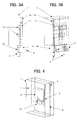
- FIGS. 1A and 1B are schematic views of a cabinet on which a piping structure for circulating a refrigerant used to cool a heat sink 10 of an inverter is set.
- the piping structure has its pipe connection ports arranged individually on a controller mounting side and a heat exchanger side.
- an inverter housing 2 is mounted on an inverter housing mounting surface 5. If necessary, a plurality of inverter housings (not shown in FIGS. 1A and 1B ) may be arranged in the cabinet 1.
- Heat-exchanger-side pipe connection ports 3 are disposed so as to extend through the inverter housing mounting surface 5, on a controller mounting side 7 where the inverter housing 2 is mounted (or on the side opposite from the side (heat exchanger side 4) where the heat sink (heat exchanger) for cooling power elements and resistors is located). Further, controller-mounting-side pipe connection ports 6 are disposed so as to extend on the controller mounting side 7.
- a refrigerant supply line 8 through which the refrigerant supplied from the refrigerant cooling device 9 is circulated has one end connected to one of the heat-exchanger-side pipe connection ports 3 or the controller-mounting-side pipe connection ports 6 and the other end connected to the cooling device 9.
- the refrigerant cooling device 9 penetrates an appropriate part of a wall of the cabinet 1 and is situated in a proper position outside the cabinet 1.
- the refrigerant that is cyclically fed from the cooling device 9 may suitably be a gas such as nitrogen gas, a liquid such as water or oil, or a solid-liquid slurry based on water and ice.
- FIG. 1A shows a state in which the refrigerant supply line 8 is connected to the controller-mounting-side pipe connection port 6, and FIG. 1B shows a state in which the line 8 is connected to the heat-exchanger-side pipe connection port 3.
- FIGS. 2A and 2B show an example in which branching points 12 from which passages diverge are formed at parts of the heat sink 10.
- FIGS. 2A and 2B show the way the heat sink 10 itself is formed with the pipe connection ports 3 and 6 on the heat-exchanger and controller-mounting sides, respectively, of the cabinet.
- the passage branching points 12 from which the heat-exchanger-side pipe connection ports 3 and the controller-mounting-side pipe connection ports 6 diverge are formed inside the heat sink 10.
- the refrigerant that is cyclically fed through the heat-exchanger-side pipe connection ports 3 or the controller-mounting-side pipe connection ports 6 cools the heat sink 10 that is disposed in the inverter housing 2. Heat from heating parts 13 is released through the heat sink 10.
- the heat sink 10 is formed by joining, for example, two aluminum plates together. A groove is formed in at least one of the aluminum plates so as to define a passage for the refrigerant. If the two aluminum plates are joined together so that the groove in the one aluminum plate faces the other aluminum plate, the refrigerant passage is formed in the heat sink 10.
- the refrigerant passage may be formed by laying a pipe of a different material with high thermal conductivity, such as a copper pipe, along the groove.
- the heat sink 10 may be formed of one aluminum plate such that a groove is formed in one side surface of the aluminum plate and that the refrigerant passage is formed by laying the pipe of the different material along the groove.
- the refrigerant passage is constructed so as to extend in zigzag in a heat sink section and cool the entire heat sink 10. Since the passage branching points 12 are thus formed inside the heat sink 10, they require no dedicated installation spaces.
- FIGS. 3A and 3B show an example in which a pipe connection port setting part 14 is connected to the heat sink 10 so as to form branch passages.
- the heat sink 10 itself has so simple a construction that it can be reduced in thickness.
- the pipe connection port setting part 14 includes pipe connection ports connected to the heat sink 10, heat-exchanger-side pipe connection ports 3, and controller-mounting-side pipe connection ports 6. Since the pipe connection port setting part 14 is independent of the heat sink 10, the respective positions of the pipe connection ports can be suitably adjusted by changing the shape of the part 14 as required.
- FIG. 4 is a perspective view showing a cabinet structure using a form of pipe connection.
- the inverter housing mounting surface 5 of the cabinet 1 is provided with a panel cut 15, which serves as an operation opening for pipe connection disposed on the heat exchanger side 4 from the controller mounting side 7.
- the heat exchanger side 4 and the controller mounting side 7 can be separated by closing the panel cut 15 lest heat or oil mist be transferred from the heat exchanger side 4 to the controller mounting side 7.
Landscapes
- Engineering & Computer Science (AREA)
- Microelectronics & Electronic Packaging (AREA)
- Physics & Mathematics (AREA)
- Thermal Sciences (AREA)
- Cooling Or The Like Of Electrical Apparatus (AREA)
- Inverter Devices (AREA)
- Rectifiers (AREA)
Applications Claiming Priority (1)
| Application Number | Priority Date | Filing Date | Title |
|---|---|---|---|
| JP2007160941A JP4216319B2 (ja) | 2007-06-19 | 2007-06-19 | インバータ筐体の冷却構造 |
Publications (2)
| Publication Number | Publication Date |
|---|---|
| EP2007183A2 true EP2007183A2 (fr) | 2008-12-24 |
| EP2007183A3 EP2007183A3 (fr) | 2010-04-14 |
Family
ID=39765036
Family Applications (1)
| Application Number | Title | Priority Date | Filing Date |
|---|---|---|---|
| EP08157019A Withdrawn EP2007183A3 (fr) | 2007-06-19 | 2008-05-27 | Structure de refroidissement pour un boîtier d'inverseur |
Country Status (4)
| Country | Link |
|---|---|
| US (1) | US20080315736A1 (fr) |
| EP (1) | EP2007183A3 (fr) |
| JP (1) | JP4216319B2 (fr) |
| CN (1) | CN101329147B (fr) |
Cited By (2)
| Publication number | Priority date | Publication date | Assignee | Title |
|---|---|---|---|---|
| US9923112B2 (en) | 2008-02-11 | 2018-03-20 | Suncore Photovoltaics, Inc. | Concentrated photovoltaic system modules using III-V semiconductor solar cells |
| US20200053912A1 (en) * | 2017-03-21 | 2020-02-13 | Lg Innotek Co., Ltd. | Converter |
Families Citing this family (9)
| Publication number | Priority date | Publication date | Assignee | Title |
|---|---|---|---|---|
| KR101275186B1 (ko) * | 2011-03-30 | 2013-06-14 | 엘지전자 주식회사 | 인버터 장치 및 이를 구비한 전기차량 |
| WO2012146335A1 (fr) * | 2011-04-28 | 2012-11-01 | Sew-Eurodrive Gmbh & Co. Kg | Agencement permettant de thermoréguler des éléments produisant de la chaleur, en particulier de les refroidir, à l'aide d'une plaque de refroidissement |
| DE202012008739U1 (de) * | 2012-09-12 | 2013-12-16 | Abb Technology Ag | Kühlkreislauf mit ausreichend knapp bemessenem Wärmetauscher |
| JP5694278B2 (ja) * | 2012-11-21 | 2015-04-01 | 三菱電機株式会社 | 電力変換装置 |
| KR101477623B1 (ko) * | 2013-04-22 | 2014-12-30 | 송암시스콤 주식회사 | 인버터 시스템의 냉각장치 |
| KR102873677B1 (ko) * | 2019-11-25 | 2025-10-21 | 엘지이노텍 주식회사 | 컨버터 |
| CN111163615B (zh) * | 2019-12-06 | 2022-02-18 | 苏州浪潮智能科技有限公司 | 一种数据中心交换机外置液冷散热系统 |
| JP7532788B2 (ja) * | 2020-02-05 | 2024-08-14 | 株式会社レゾナック | 電池モジュール |
| JP6806276B1 (ja) * | 2020-03-05 | 2021-01-06 | 富士電機株式会社 | 電力変換装置 |
Citations (1)
| Publication number | Priority date | Publication date | Assignee | Title |
|---|---|---|---|---|
| JPH0890252A (ja) | 1994-09-27 | 1996-04-09 | Miyachi Technos Corp | インバータ式溶接電源ユニット |
Family Cites Families (9)
| Publication number | Priority date | Publication date | Assignee | Title |
|---|---|---|---|---|
| US1862707A (en) * | 1930-06-14 | 1932-06-14 | William L Rifenberick | Heat exchanger unit |
| US4268850A (en) * | 1979-05-11 | 1981-05-19 | Electric Power Research Institute | Forced vaporization heat sink for semiconductor devices |
| DE3417986A1 (de) * | 1984-05-15 | 1985-11-21 | kabelmetal electro GmbH, 3000 Hannover | Anordnung zum abfuehren der verlustwaerme von in gehaeusen angeordneten leiterplatten |
| JP3254001B2 (ja) * | 1991-04-08 | 2002-02-04 | ゼネラル・エレクトリック・カンパニイ | 半導体モジュール用の一体化放熱器 |
| JPH04364379A (ja) * | 1991-06-10 | 1992-12-16 | Mitsubishi Electric Corp | インバータ装置 |
| US5801442A (en) * | 1996-07-22 | 1998-09-01 | Northrop Grumman Corporation | Microchannel cooling of high power semiconductor devices |
| DE19815645C1 (de) * | 1998-04-07 | 1999-08-19 | Siemens Ag | Umrichteranordnung mit Kühleinrichtung |
| DE102004054311B4 (de) * | 2004-11-09 | 2007-01-11 | Rittal Res Electronic Systems Gmbh & Co. Kg | Kühlanordnung |
| FI122185B (fi) * | 2005-09-05 | 2011-09-30 | Vacon Oyj | Järjestely nestejäähdytteisten sähkölaitteiden jäähdytystä varten |
-
2007
- 2007-06-19 JP JP2007160941A patent/JP4216319B2/ja not_active Expired - Fee Related
-
2008
- 2008-05-23 US US12/125,989 patent/US20080315736A1/en not_active Abandoned
- 2008-05-27 EP EP08157019A patent/EP2007183A3/fr not_active Withdrawn
- 2008-06-16 CN CN2008101099860A patent/CN101329147B/zh not_active Expired - Fee Related
Patent Citations (1)
| Publication number | Priority date | Publication date | Assignee | Title |
|---|---|---|---|---|
| JPH0890252A (ja) | 1994-09-27 | 1996-04-09 | Miyachi Technos Corp | インバータ式溶接電源ユニット |
Cited By (5)
| Publication number | Priority date | Publication date | Assignee | Title |
|---|---|---|---|---|
| US9923112B2 (en) | 2008-02-11 | 2018-03-20 | Suncore Photovoltaics, Inc. | Concentrated photovoltaic system modules using III-V semiconductor solar cells |
| US20200053912A1 (en) * | 2017-03-21 | 2020-02-13 | Lg Innotek Co., Ltd. | Converter |
| EP3606306A4 (fr) * | 2017-03-21 | 2020-03-18 | LG Innotek Co., Ltd. | Convertisseur |
| US10925181B2 (en) | 2017-03-21 | 2021-02-16 | Lg Innotek Co., Ltd. | Converter |
| US11304336B2 (en) | 2017-03-21 | 2022-04-12 | Lg Innotek Co., Ltd. | Converter |
Also Published As
| Publication number | Publication date |
|---|---|
| EP2007183A3 (fr) | 2010-04-14 |
| JP2009004405A (ja) | 2009-01-08 |
| US20080315736A1 (en) | 2008-12-25 |
| JP4216319B2 (ja) | 2009-01-28 |
| CN101329147A (zh) | 2008-12-24 |
| CN101329147B (zh) | 2010-08-11 |
Similar Documents
| Publication | Publication Date | Title |
|---|---|---|
| EP2007183A2 (fr) | Structure de refroidissement pour un boîtier d'inverseur | |
| EP2306101B1 (fr) | Climatiseur | |
| US20070256957A1 (en) | Sub-rack with housing for receiving plug-in modules | |
| JP5110492B2 (ja) | ねじ付き挿入部材を備えた小型の両面冷却板 | |
| JP2007536603A (ja) | 機器及びネットワーク用キャビネットにおける電気モジュラユニットの冷却のための構成 | |
| US20110226445A1 (en) | Heat exchanger | |
| CN111094857B (zh) | 热交换器单元和空调装置 | |
| EP3421905A1 (fr) | Tuyau composite, appareil de réfrigération et procédé de fabrication d'un tuyau composite | |
| JP2009299957A (ja) | 空気調和機 | |
| EP2517541B1 (fr) | Structure de montage conduisant la chaleur, procédé et agencement de boîtier de station de base radio pour le montage de modules électroniques | |
| JPWO2021024409A1 (ja) | チリングユニット | |
| CN113115565B (zh) | 一种具有冷循环系统的整合式机房 | |
| CN219607223U (zh) | 空调装置 | |
| JP2010032071A (ja) | 冷凍装置における電装品ユニットの設置構造及び設置方法 | |
| WO2025228003A1 (fr) | Armoire de serveur et système d'armoire complète | |
| JP2015095967A (ja) | 制御盤及びポンプ装置 | |
| CN218135783U (zh) | 一种激光设备用双面冷却板 | |
| US20260092723A1 (en) | Outdoor machine and air conditioner | |
| CN213152744U (zh) | 一种电气柜空调的承载件及电气柜空调 | |
| JP2002271076A (ja) | 電気機器収納箱の冷却装置 | |
| CN120734603A (zh) | 一种用于特种气体管道的焊接设备 | |
| JP4859554B2 (ja) | 室外ユニット | |
| EP3382291A1 (fr) | Appareil de réfrigération, tuyau composite et procédé d'assemblage de corps de refroidissement | |
| CN121397960A (zh) | 热源装置及暖通设备 | |
| PL240393B1 (pl) | Wymiennik ciepła chłodzony cieczą zintegrowany z obudową ognioszczelną |
Legal Events
| Date | Code | Title | Description |
|---|---|---|---|
| PUAI | Public reference made under article 153(3) epc to a published international application that has entered the european phase |
Free format text: ORIGINAL CODE: 0009012 |
|
| AK | Designated contracting states |
Kind code of ref document: A2 Designated state(s): AT BE BG CH CY CZ DE DK EE ES FI FR GB GR HR HU IE IS IT LI LT LU LV MC MT NL NO PL PT RO SE SI SK TR |
|
| AX | Request for extension of the european patent |
Extension state: AL BA MK RS |
|
| PUAL | Search report despatched |
Free format text: ORIGINAL CODE: 0009013 |
|
| AK | Designated contracting states |
Kind code of ref document: A3 Designated state(s): AT BE BG CH CY CZ DE DK EE ES FI FR GB GR HR HU IE IS IT LI LT LU LV MC MT NL NO PL PT RO SE SI SK TR |
|
| AX | Request for extension of the european patent |
Extension state: AL BA MK RS |
|
| 17P | Request for examination filed |
Effective date: 20100604 |
|
| 17Q | First examination report despatched |
Effective date: 20100701 |
|
| AKX | Designation fees paid |
Designated state(s): DE |
|
| RAP1 | Party data changed (applicant data changed or rights of an application transferred) |
Owner name: FANUC CORPORATION |
|
| STAA | Information on the status of an ep patent application or granted ep patent |
Free format text: STATUS: THE APPLICATION IS DEEMED TO BE WITHDRAWN |
|
| 18D | Application deemed to be withdrawn |
Effective date: 20121201 |