EP2006232B1 - Elevator device - Google Patents
Elevator device Download PDFInfo
- Publication number
- EP2006232B1 EP2006232B1 EP06731756.0A EP06731756A EP2006232B1 EP 2006232 B1 EP2006232 B1 EP 2006232B1 EP 06731756 A EP06731756 A EP 06731756A EP 2006232 B1 EP2006232 B1 EP 2006232B1
- Authority
- EP
- European Patent Office
- Prior art keywords
- value
- speed command
- current
- car
- speed
- Prior art date
- Legal status (The legal status is an assumption and is not a legal conclusion. Google has not performed a legal analysis and makes no representation as to the accuracy of the status listed.)
- Ceased
Links
Images


Classifications
-
- B—PERFORMING OPERATIONS; TRANSPORTING
- B66—HOISTING; LIFTING; HAULING
- B66B—ELEVATORS; ESCALATORS OR MOVING WALKWAYS
- B66B1/00—Control systems of elevators in general
- B66B1/24—Control systems with regulation, i.e. with retroactive action, for influencing travelling speed, acceleration, or deceleration
- B66B1/28—Control systems with regulation, i.e. with retroactive action, for influencing travelling speed, acceleration, or deceleration electrical
- B66B1/30—Control systems with regulation, i.e. with retroactive action, for influencing travelling speed, acceleration, or deceleration electrical effective on driving gear, e.g. acting on power electronics, on inverter or rectifier controlled motor
Definitions
- the present invention relates to an elevator apparatus employing a plurality of hoisting machines to raise and lower a single car.
- a speed pattern to be applied to a hoisting machine is changed based on a load of a car and a moving distance of the car, to thereby adjust acceleration of the car and a maximum speed of the car. That is, the acceleration of the car and the maximum speed of the car each are raised within respective allowable ranges of drive components such as a motor and an inverter, thereby being capable of shortening running time of the car (e.g., see Patent Document 1).
- Patent Document 1 JP 2003-238037 A
- the conventional elevator control device configured as described above, or shown in JP 2005 289532 , however, burdens on the drive components are increased in a case where there occurs a major detection error in the load of the car or a great loss during running.
- the potentials of the drive components cannot be brought out to the maximum when the speed pattern is determined in consideration of the detection error in the load or the loss during running.
- the conventional elevator control device is designed to control a single hoisting machine, and hence cannot be applied to an elevator apparatus of such a type that a single car is raised and lowered by a plurality of hoisting machines.
- the present invention has been made to solve the above-mentioned problems, and it is therefore an object of the present invention to obtain an elevator apparatus that makes it possible to operate drive components more efficiently and cause a car to run more stably by means of a plurality of hoisting machines.
- An elevator apparatus includes: a car; a plurality of hoisting machines for raising and lowering the car; and an elevator control device for controlling the hoisting machines, in which the elevator control device generates speed commands separately for the hoisting machines, and applies, when a current value of one of the hoisting machines reaches a current set value , which is set in advance during acceleration of the car, the speed command for that one of the hoisting machines whose current value is at or above the current set value, to the other hoisting machine as well.
- an elevator apparatus includes: a car; a plurality of hoisting machines for raising and lowering the car; and an elevator control device for controlling the hoisting machines, in which the elevator control device generates speed commands separately for the hoisting machines, and applies, when a voltage value which is applied to one of the hoisting machines reaches a voltage set value , which is set in advance during acceleration of the car, the speed command for that one of the hoisting machines whose voltage value is at or above the voltage set value, to the other hoisting machine as well.
- Fig. 1 is a schematic diagram showing an elevator apparatus according to Embodiment 1 of the present invention.
- a car 1, a first counterweight 2, and a second counterweight 3 are raised and lowered within a hoistway by a first hoisting machine 4 and a second hoisting machine 5.
- the first hoisting machine 4 has a first motor 6, a first drive sheave 7 that is rotated by the first motor 6, a first speed detector 8 for detecting a rotational speed of the first motor 6, and a first brake (not shown) for braking rotation of the first drive sheave 7.
- the second hoisting machine 5 has a second motor 9, a second drive sheave 10 that is rotated by the second motor 9, a second speed detector 11 for detecting a rotational speed of the second motor 9, and a second brake (not shown) for braking rotation of the second drive sheave 10.
- a second speed detector 11 for detecting a rotational speed of the second motor 9, and a second brake (not shown) for braking rotation of the second drive sheave 10.
- the first speed detector 8 and the second speed detector 11 are, for example, encoders, resolvers, or the like.
- a plurality of first main ropes 12 (only one of the first main ropes 12 is illustrated in Fig. 1 ) for suspending the car 1 and the first counterweight 2 are wound around the first drive sheave 7.
- a plurality of second main ropes 13 (only one of the second main ropes 13 is illustrated in Fig. 1 ) for suspending the car 1 and the second counterweight 3 are wound around the second drive sheave 10.
- the first motor 6 is supplied with a power from a power supply 16 via a first converter 14 and a first inverter 15.
- a first smoothing capacitor 17 is connected between the first converter 14 and the first inverter 15.
- a first regenerative resistor 18 and a first regenerative switch 19 are connected in parallel to the first smoothing capacitor 17.
- a value of a current supplied from the first inverter 15 to the first motor 6 is detected by a first current detector 20.
- the second motor 9 is supplied with a power from a power supply 23 via a second converter 21 and a second inverter 22.
- a second smoothing capacitor 24 is connected between the second converter 21 and the second inverter 22.
- a second regenerative resistor 25 and a second regenerative switch 26 are connected in parallel to the second smoothing capacitor 24.
- a value of a current supplied from the second inverter 22 to the second motor 9 is detected by a second current detector 27.
- Alternating voltages from the power supplies 16 and 23 each are converted into direct voltages by the converters 14 and 21 respectively and smoothed by the smoothing capacitors 17 and 24 respectively.
- the regenerative resistors 18 and 25 consume power regenerated during regenerative operation of the hoisting machines 4 and 5 as heat, respectively.
- a corresponding one of the regenerative switches 19 and 26 is turned ON to cause a current to flow through a corresponding one of the resistors 18 and 25.
- each of the regenerative switches 19 and 26 When each of the regenerative switches 19 and 26 is ON, the current flows through a corresponding one of the regenerative resistors 18 and 25, so the voltage of a corresponding one of the smoothing capacitors 17 and 24 drops.
- a corresponding one of the regenerative switches 19 and 26 When the voltage of each of the smoothing capacitors 17 and 24 drops below a predetermined value, a corresponding one of the regenerative switches 19 and 26 is turned OFF, so supply of the current to a corresponding one of the regenerative resistors 18 and 25 is stopped. As a result, the voltage of each of the smoothing capacitors 17 and 24 is stopped from dropping.
- the direct voltage input to each of the inverters 15 and 22 is controlled within a prescribed range by turning a corresponding one of the regenerative switches 19 and 26 on and off in accordance with the voltage of a corresponding one of the smoothing capacitors 17 and 24.
- the regenerative switches 19 and 26 are, for example, semiconductor switches.
- the first inverter 15 and the second inverter 22 are controlled by an elevator control device 31. That is, operations of the first hoisting machine 4 and the second hoisting machine 5 are controlled by the elevator control device 31.
- the elevator control device 31 has a first hoisting machine control section 32 for controlling the operation of the first hoisting machine 4, a second hoisting machine control section 33 for controlling the operation of the second hoisting machine 5, and a speed command changing section 34.
- the first hoisting machine control section 32 has a first speed command generating section 35, a first speed control section 36, and a first current control section 37.
- the first speed command generating section 35 generates a speed command for the car 1, namely, a speed command for the first hoisting machine 4 in accordance with registrations of calls from landings or calls from within the car 1.
- the first speed control section 36 calculates a torque value and generates a torque command such that the rotational speed of the first motor 6 coincides with the value of the speed command, based on the speed command generated by the first speed command generating section 35 and information from the first speed detector 8.
- the first current control section 37 controls the first inverter 15 based on a current detection signal from the first current detector 20 and the torque command from the first speed control section 36. More specifically, the first current control section 37 converts the torque command from the first speed control section 36 into a current command value, and outputs a signal for driving the first inverter 15 such that a value of the current detected by the first current detector 20 coincides with the current command value.
- the second hoisting machine control section 33 has a second speed command generating section 38, a second speed control section 39, and a second current control section 40.
- the second speed command generating section 38 generates a speed command for the car 1, namely, a speed command for the second hoisting machine 5 in accordance with registrations of calls from the landings or calls from within the car 1.
- the second speed control section 39 calculates a torque value and generates a torque command such that the rotational speed of the second motor 9 coincides with the value of the speed command, based on the speed command generated by the second speed command generating section 38 and information from the second speed detector 11.
- the second current control section 40 controls the second inverter 22 based on a current detection signal from the second current detector 27 and the torque command from the second speed control section 39. More specifically, the second current control section 40 converts the torque command from the second speed control section 39 into a current command value, and outputs a signal for driving the second inverter 22 such that a value of the current detected by the second current detector 27 coincides with the current command value.
- Vector control is adopted in controlling the currents flowing through the inverters 15 and 22 by means of the current control sections 37 and 40 respectively. That is, each of the current control sections 37 and 40 calculates a voltage value to be output by a corresponding one of the inverters 15 and 22 in accordance with the current command value obtained through conversion of the torque command and the current value of a corresponding one of the motors 6 and 9 and a magnetic pole position (a rotational position) thereof, which has been detected by a corresponding one of the current detectors 20 and 27, and outputs an on and off switching pattern to a transistor as a built-in component in the corresponding one of the inverters 15 and 22.
- Each of the speed command generating sections 35 and 38 generates a speed command separately for a corresponding one of the hoisting machines 4 and 5 so as to raise the maximum speed of the car 1 and the acceleration of the car 1 to the maximum possible extent within allowable ranges of drive components (the motors 6 and 9 and electric components for driving the motors 6 and 9) and hence shorten the running time of the car 1.
- the speed command changing section 34 monitors the current values input to the motors 6 and 9 from the inverters 15 and 22 respectively and the values of applied voltages (inverter command values) calculated by the current control sections 37 and 40 respectively, and prevents the first speed command generating section 35 and the second speed command generating section 38 from generating different speed commands.
- the speed command changing section 34 thereafter changes the speed command value of that one of the speed command generating sections 35 and 38, which is on the side where the current set value has not been reached, into the same value as the speed command value generated by that one of the speed command generating sections 35 and 38 which is on the side where the current set value has been reached.
- the speed command changing section 34 thereafter changes the speed command value of that one of the speed command generating sections 35 and 38, which is on the side where the voltage set value has not been reached, into the same value as the speed command value generated by that one of the speed command generating sections 35 and 38 which is on the side where the voltage set value has been reached.
- the elevator control device 31 is constituted by a computer having a calculation processing section (a CPU), a storage section (a ROM, a RAM, a hard disk, and the like), and signal input/output sections. That is, the functions of the speed command changing section 34, the speed command generating sections 35 and 38, the speed control sections 36 and 39, and the current control sections 37 and 40 are realized by the computer.
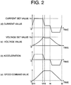
- Fig. 2 is an explanatory diagram showing how the speed command generating section 35 of Fig. 1 generates a speed command.
- a graph (a) shows an example of time-based changes in speed command value.
- a graph (b) shows time-based changes in the acceleration of the car 1 which correspond to the graph (a) .
- a graph (c) shows time-based changes in the applied voltage value output from the current control section 37.
- a graph (d) shows time-based changes in the current value input to the motor 6.
- the motor 6 is activated with a jerk j1 [m/s 3 ] (a derivative value of the acceleration of the graph (b)) at, for example, a time t0.
- the acceleration of the car 1 is raised with the jerk j1 [m/s 3 ] until a time t1 at which the current value indicated by the graph (d) reaches a current set value I 0 .
- the jerk is held equal to 0 after the time t1, and the car 1 is accelerated with a constant acceleration until a time t2 at which the voltage value indicated by the graph (c) reaches a voltage set value V 0 .
- the speed command is generated with a jerk j2 [m/s 3 ] from the time t2 to a time t3 so as to ensure a smooth transition at constant-speed running.
- a time t4 corresponding to the end of constant-speed running and a time t5 corresponding to the completion of running are determined in accordance with a running distance required for the car 1, a preset deceleration ⁇ [m/s 2 ], a jerk j3 [m/s 3 ] during deceleration from constant-speed running, and a jerk j4 [m/s 3 ] during a transition from constant-deceleration running to a stoppage of running, so a speed pattern is generated.
- the method of generating the speed command as described above is also adopted by the speed command generating section 38. It should be noted herein that the current set value I 0 and the voltage set value V 0 are set such that allowable limit values for the motors 6 and 9 and the electric components for driving the motors 6 and 9, for example, power-supply capacities and allowable currents for the inverters 15 and 22, are not exceeded.
- Fig. 3 is an explanatory diagram showing how the speed command changing section 34 of Fig. 1 performs a speed command changing operation based on the monitoring of a current value.
- a graph (a) shows an example of time-based changes in speed command value.
- a graph (b) shows time-based changes in the current value of the second hoisting machine 5 (the second motor 9).
- a graph (c) shows time-based changes in the current value of the first hoisting machine 4 (the first motor 6).
- the hoisting machines 4 and 5 are activated to start accelerating the car 1 at the time t0.
- the current value of the second hoisting machine 5 reaches the current set value I 0 at the time t1.
- the current value of the first hoisting machine 4 reaches the current set value I 0 at the time t2, which is preceded by the time t1. That is, in the example of Fig. 3 , the current value of the second hoisting machine 5 reaches the current set value I 0 before the current value of the first hoisting machine 4 reaches the current set value I 0 .
- the speed command changing section 34 changes the speed command value of the first speed command generating section 35 (as indicated by broken lines of the graph (a)) into the speed command value generated by the second speed command generating section 38 (as indicated by a solid line of the graph (a)).
- Fig. 4 is an explanatory diagram showing how the speed command changing section 34 of Fig. 1 performs a speed command changing operation based on the monitoring of a voltage value.
- a graph (a) shows an example of time-based changes in speed command value.
- a graph (b) shows time-based changes in the value of the voltage applied to the second hoisting machine 5.
- a graph (c) shows time-based changes in the value of the voltage applied to the first hoisting machine 4.
- the hoisting machines 4 and 5 are activated to start accelerating the car 1 at the time t0.
- the value of the voltage applied to the second hoisting machine 5 reaches the voltage set value V 0 at the time t2.
- the value of the voltage applied to the first hoisting machine 4 reaches the voltage set value V 0 at the time t3, which is preceded by the time t2. That is, in the example of Fig. 4 , the value of the voltage applied to the second hoisting machine 5 reaches the voltage set value V 0 before the value of the voltage applied to the first hoisting machine 4 reaches the voltage set value V 0 .
- the speed command changing section 34 changes the speed command value of the first speed command generating section 35 (as indicated by broken lines of the graph (a)) into the speed command value generated by the second speed command generating section 38 (as indicated by a solid line of the graph (a)).
- the drive components can be more efficiently operated without being affected by a detection error in the load of the car 1 or a loss caused during running. Further, the speed commands for the first hoisting machine 4 and the second hoisting machine 5 can be prevented from becoming different from each other, so the car 1 can be caused to run stably by the two hoisting machines 4 and 5.
- the single elevator control device 31 performs the functions of the first hoisting machine control section 32, the second hoisting machine control section 33, and the speed command changing section 34.
- the elevator control device 31 may be divided into a plurality of control devices to perform those functions respectively.
- separate speed command changing sections may be employed to monitor a current and a voltage individually.
- the voltage values calculated by the current control sections 37 and 40 are monitored by the speed command changing section 34.
- a duty value as a ratio of an ON time period of each of the inverters 15 and 22 within a predetermined time period may be monitored instead.
- Fig. 5 is an explanatory diagram showing an example of a command signal for each of the inverters 15 and 22 of Fig. 1 .
- the ratio of the ON time period of each of the inverters 15 and 22 within a sampling time cycle T increases as the speed of the car 1 increases after the car 1 has started running.
- the duty value which is calculated as ⁇ Ti/T, is prosectional to the voltage applied to a corresponding one of the hoisting machines 4 and 5. Accordingly, the same control as in Embodiment 1 of the present invention can also be performed by monitoring the current flowing through each of the hoisting machines 4 and 5 and the duty value.
- Fig. 6 is a schematic diagram showing an elevator apparatus according to Embodiment 2 of the present invention.
- an elevator control device 41 has the first hoisting machine control section 32, the second hoisting machine control section 33, and a communication section 42. Information can be transmitted between the first speed command generating section 35 and the second speed command generating section 38 via the communication section 42.
- the first speed command generating section 35 monitors whether or not the applied voltage value calculated by the first current control section 37 reaches a voltage set value during acceleration of the first motor 6, and whether or not a current value input to the first motor 6 from the first inverter 15 reaches a current set value during acceleration of the first motor 6.
- the second speed command generating section 38 monitors whether or not the applied voltage value calculated by the second current control section 40 reaches a voltage set value during acceleration of the second motor 9, and whether or not a current value input to the second motor 9 from the second inverter 22 reaches a current set value during acceleration of the second motor 9.
- a corresponding one of the speed command generating sections 35 and 38 transmits the information indicative thereof to the other speed command generating section 35 or 38 on the side where the current set value has not been reached.
- the speed command generating section 35 or 38 changes the speed command value thereof into the same value as the speed command value generated by the other speed command generating section 35 or 38 on the side where the current set value has been reached.
- Embodiment 2 of the present invention is identical to Embodiment 1 of the present invention in other configurational details.
- the speed command generating sections 35 and 38 may be configured to transmit monitoring results of current and voltage to each other. In this manner, a simplification in configuration can be achieved through the omission of the speed command changing section 34 of Embodiment 1 of the present invention.
- a function of the elevator control device 41 of Embodiment 2 of the present invention may be performed by either a single device or a plurality of separate devices.
- the converters 14 and 21 and the power supplies 16 and 23 are employed as the components corresponding to the first hoisting machine 4 and the second hoisting machine 5 respectively.
- a common converter and a common power supply may be employed for the first hoisting machine 4 and the second hoisting machine 5.
- the present invention is also applicable to an elevator apparatus employing three or more hoisting machines to raise and lower a single car.
- the jerk is regarded as a constant for convenience of explanation.
- the jerk may be a function of time. In this case, a reduction in running time and an improvement to obtain a comfortable ride can be achieved.
- each of the main ropes 12 and 13 may be designed as either a rope having a circular cross-section or a belt-shaped rope having a flat cross-section.
- the speed control of the first hoisting machine 4 and the second hoisting machine 5 is performed by the computer.
- this speed control can also be performed by a circuit for processing analog electric signals.
Landscapes
- Engineering & Computer Science (AREA)
- Automation & Control Theory (AREA)
- Elevator Control (AREA)
- Control Of Ac Motors In General (AREA)
Description
- The present invention relates to an elevator apparatus employing a plurality of hoisting machines to raise and lower a single car.
- In a conventional elevator control device, a speed pattern to be applied to a hoisting machine is changed based on a load of a car and a moving distance of the car, to thereby adjust acceleration of the car and a maximum speed of the car. That is, the acceleration of the car and the maximum speed of the car each are raised within respective allowable ranges of drive components such as a motor and an inverter, thereby being capable of shortening running time of the car (e.g., see Patent Document 1).
- Patent Document 1:
JP 2003-238037 A - In the conventional elevator control device configured as described above, or shown in
JP 2005 289532 - The present invention has been made to solve the above-mentioned problems, and it is therefore an object of the present invention to obtain an elevator apparatus that makes it possible to operate drive components more efficiently and cause a car to run more stably by means of a plurality of hoisting machines. Means for solving the Problems
- An elevator apparatus according to the present invention includes: a car; a plurality of hoisting machines for raising and lowering the car; and an elevator control device for controlling the hoisting machines, in which the elevator control device generates speed commands separately for the hoisting machines, and applies, when a current value of one of the hoisting machines reaches a current set value , which is set in advance during acceleration of the car, the speed command for that one of the hoisting machines whose current value is at or above the current set value, to the other hoisting machine as well.
- Further, an elevator apparatus according to the present invention includes: a car; a plurality of hoisting machines for raising and lowering the car; and an elevator control device for controlling the hoisting machines, in which the elevator control device generates speed commands separately for the hoisting machines, and applies, when a voltage value which is applied to one of the hoisting machines reaches a voltage set value , which is set in advance during acceleration of the car, the speed command for that one of the hoisting machines whose voltage value is at or above the voltage set value, to the other hoisting machine as well.
-
-
Fig. 1 is a schematic diagram showing an elevator apparatus according to Embodiment 1 of the present invention. -
Fig. 2 is an explanatory diagram showing how a speed command generating section ofFig. 1 generates a speed command. -
Fig. 3 is an explanatory diagram showing how a speed command changing section ofFig. 1 performs a speed command changing operation based on the monitoring of a current value. -
Fig. 4 is an explanatory diagram showing how the speed command changing section ofFig. 1 performs a speed command changing operation based on the monitoring of a voltage value. -
Fig. 5 is an explanatory diagram showing an example of a command signal for each of inverters ofFig. 1 . -
Fig. 6 is a schematic diagram showing an elevator apparatus according toEmbodiment 2 of the present invention. - Preferred embodiments of the present invention will be described hereinafter with reference to the drawings.
-
Fig. 1 is a schematic diagram showing an elevator apparatus according to Embodiment 1 of the present invention. A car 1, afirst counterweight 2, and asecond counterweight 3 are raised and lowered within a hoistway by a first hoistingmachine 4 and asecond hoisting machine 5. The first hoistingmachine 4 has afirst motor 6, afirst drive sheave 7 that is rotated by thefirst motor 6, afirst speed detector 8 for detecting a rotational speed of thefirst motor 6, and a first brake (not shown) for braking rotation of thefirst drive sheave 7. - The second hoisting
machine 5 has asecond motor 9, asecond drive sheave 10 that is rotated by thesecond motor 9, asecond speed detector 11 for detecting a rotational speed of thesecond motor 9, and a second brake (not shown) for braking rotation of thesecond drive sheave 10. Employed as thefirst speed detector 8 and thesecond speed detector 11 are, for example, encoders, resolvers, or the like. - A plurality of first main ropes 12 (only one of the first
main ropes 12 is illustrated inFig. 1 ) for suspending the car 1 and thefirst counterweight 2 are wound around thefirst drive sheave 7. A plurality of second main ropes 13 (only one of the secondmain ropes 13 is illustrated inFig. 1 ) for suspending the car 1 and thesecond counterweight 3 are wound around thesecond drive sheave 10. - The
first motor 6 is supplied with a power from apower supply 16 via afirst converter 14 and afirst inverter 15. Afirst smoothing capacitor 17 is connected between thefirst converter 14 and thefirst inverter 15. A firstregenerative resistor 18 and a firstregenerative switch 19 are connected in parallel to thefirst smoothing capacitor 17. A value of a current supplied from thefirst inverter 15 to thefirst motor 6 is detected by a firstcurrent detector 20. - The
second motor 9 is supplied with a power from apower supply 23 via asecond converter 21 and asecond inverter 22. Asecond smoothing capacitor 24 is connected between thesecond converter 21 and thesecond inverter 22. A secondregenerative resistor 25 and a secondregenerative switch 26 are connected in parallel to thesecond smoothing capacitor 24. A value of a current supplied from thesecond inverter 22 to thesecond motor 9 is detected by a secondcurrent detector 27. - Alternating voltages from the
power supplies converters smoothing capacitors regenerative resistors hoisting machines smoothing capacitors regenerative switches resistors - When each of the
regenerative switches regenerative resistors smoothing capacitors smoothing capacitors regenerative switches regenerative resistors smoothing capacitors - As described above, the direct voltage input to each of the
inverters regenerative switches smoothing capacitors regenerative switches - The
first inverter 15 and thesecond inverter 22 are controlled by anelevator control device 31. That is, operations of thefirst hoisting machine 4 and the second hoistingmachine 5 are controlled by theelevator control device 31. Theelevator control device 31 has a first hoistingmachine control section 32 for controlling the operation of thefirst hoisting machine 4, a second hoistingmachine control section 33 for controlling the operation of thesecond hoisting machine 5, and a speedcommand changing section 34. - The first hoisting
machine control section 32 has a first speedcommand generating section 35, a firstspeed control section 36, and a firstcurrent control section 37. The first speedcommand generating section 35 generates a speed command for the car 1, namely, a speed command for thefirst hoisting machine 4 in accordance with registrations of calls from landings or calls from within the car 1. - The first
speed control section 36 calculates a torque value and generates a torque command such that the rotational speed of thefirst motor 6 coincides with the value of the speed command, based on the speed command generated by the first speedcommand generating section 35 and information from thefirst speed detector 8. - The first
current control section 37 controls thefirst inverter 15 based on a current detection signal from the firstcurrent detector 20 and the torque command from the firstspeed control section 36. More specifically, the firstcurrent control section 37 converts the torque command from the firstspeed control section 36 into a current command value, and outputs a signal for driving thefirst inverter 15 such that a value of the current detected by the firstcurrent detector 20 coincides with the current command value. - The second hoisting
machine control section 33 has a second speedcommand generating section 38, a secondspeed control section 39, and a secondcurrent control section 40. The second speedcommand generating section 38 generates a speed command for the car 1, namely, a speed command for thesecond hoisting machine 5 in accordance with registrations of calls from the landings or calls from within the car 1. - The second
speed control section 39 calculates a torque value and generates a torque command such that the rotational speed of thesecond motor 9 coincides with the value of the speed command, based on the speed command generated by the second speedcommand generating section 38 and information from thesecond speed detector 11. - The second
current control section 40 controls thesecond inverter 22 based on a current detection signal from the secondcurrent detector 27 and the torque command from the secondspeed control section 39. More specifically, the secondcurrent control section 40 converts the torque command from the secondspeed control section 39 into a current command value, and outputs a signal for driving thesecond inverter 22 such that a value of the current detected by the secondcurrent detector 27 coincides with the current command value. - Vector control is adopted in controlling the currents flowing through the
inverters current control sections current control sections inverters motors current detectors inverters - Each of the speed
command generating sections hoisting machines motors motors 6 and 9) and hence shorten the running time of the car 1. - The speed
command changing section 34 monitors the current values input to themotors inverters current control sections command generating section 35 and the second speedcommand generating section 38 from generating different speed commands. - More specifically, when one of the current values input to the
motors motors command changing section 34 thereafter changes the speed command value of that one of the speedcommand generating sections command generating sections - Further, when one of the applied voltage values calculated by the first
current control section 37 and the secondcurrent control section 40 reaches a voltage set value , which is set in advance during acceleration of themotors command changing section 34 thereafter changes the speed command value of that one of the speedcommand generating sections command generating sections - It should be noted herein that the
elevator control device 31 is constituted by a computer having a calculation processing section (a CPU), a storage section (a ROM, a RAM, a hard disk, and the like), and signal input/output sections. That is, the functions of the speedcommand changing section 34, the speedcommand generating sections speed control sections current control sections -
Fig. 2 is an explanatory diagram showing how the speedcommand generating section 35 ofFig. 1 generates a speed command. Referring toFig. 2 , a graph (a) shows an example of time-based changes in speed command value. A graph (b) shows time-based changes in the acceleration of the car 1 which correspond to the graph (a) . A graph (c) shows time-based changes in the applied voltage value output from thecurrent control section 37. A graph (d) shows time-based changes in the current value input to themotor 6. - According to the speed command indicated by the graph (a), the
motor 6 is activated with a jerk j1 [m/s3] (a derivative value of the acceleration of the graph (b)) at, for example, a time t0. After that, the acceleration of the car 1 is raised with the jerk j1 [m/s3] until a time t1 at which the current value indicated by the graph (d) reaches a current set value I0. The jerk is held equal to 0 after the time t1, and the car 1 is accelerated with a constant acceleration until a time t2 at which the voltage value indicated by the graph (c) reaches a voltage set value V0. - The speed command is generated with a jerk j2 [m/s3] from the time t2 to a time t3 so as to ensure a smooth transition at constant-speed running. After the time t3, a time t4 corresponding to the end of constant-speed running and a time t5 corresponding to the completion of running are determined in accordance with a running distance required for the car 1, a preset deceleration β [m/s2], a jerk j3 [m/s3] during deceleration from constant-speed running, and a jerk j4 [m/s3] during a transition from constant-deceleration running to a stoppage of running, so a speed pattern is generated.
- The method of generating the speed command as described above is also adopted by the speed
command generating section 38. It should be noted herein that the current set value I0 and the voltage set value V0 are set such that allowable limit values for themotors motors inverters -
Fig. 3 is an explanatory diagram showing how the speedcommand changing section 34 ofFig. 1 performs a speed command changing operation based on the monitoring of a current value. Referring toFig. 3 , a graph (a) shows an example of time-based changes in speed command value. A graph (b) shows time-based changes in the current value of the second hoisting machine 5 (the second motor 9). A graph (c) shows time-based changes in the current value of the first hoisting machine 4 (the first motor 6). - According to the speed command indicated by the graph (a), the
hoisting machines second hoisting machine 5 reaches the current set value I0 at the time t1. On the other hand, the current value of thefirst hoisting machine 4 reaches the current set value I0 at the time t2, which is preceded by the time t1. That is, in the example ofFig. 3 , the current value of thesecond hoisting machine 5 reaches the current set value I0 before the current value of thefirst hoisting machine 4 reaches the current set value I0. - Thus, the speed
command changing section 34 changes the speed command value of the first speed command generating section 35 (as indicated by broken lines of the graph (a)) into the speed command value generated by the second speed command generating section 38 (as indicated by a solid line of the graph (a)). -
Fig. 4 is an explanatory diagram showing how the speedcommand changing section 34 ofFig. 1 performs a speed command changing operation based on the monitoring of a voltage value. Referring toFig. 4 , a graph (a) shows an example of time-based changes in speed command value. A graph (b) shows time-based changes in the value of the voltage applied to thesecond hoisting machine 5. A graph (c) shows time-based changes in the value of the voltage applied to thefirst hoisting machine 4. - According to the speed command of the graph (a), the
hoisting machines second hoisting machine 5 reaches the voltage set value V0 at the time t2. On the other hand, the value of the voltage applied to thefirst hoisting machine 4 reaches the voltage set value V0 at the time t3, which is preceded by the time t2. That is, in the example ofFig. 4 , the value of the voltage applied to thesecond hoisting machine 5 reaches the voltage set value V0 before the value of the voltage applied to thefirst hoisting machine 4 reaches the voltage set value V0. - Thus, the speed
command changing section 34 changes the speed command value of the first speed command generating section 35 (as indicated by broken lines of the graph (a)) into the speed command value generated by the second speed command generating section 38 (as indicated by a solid line of the graph (a)). - In the elevator apparatus configured as described above, the drive components can be more efficiently operated without being affected by a detection error in the load of the car 1 or a loss caused during running. Further, the speed commands for the
first hoisting machine 4 and thesecond hoisting machine 5 can be prevented from becoming different from each other, so the car 1 can be caused to run stably by the twohoisting machines - In the foregoing example, the single
elevator control device 31 performs the functions of the first hoistingmachine control section 32, the second hoistingmachine control section 33, and the speedcommand changing section 34. However, theelevator control device 31 may be divided into a plurality of control devices to perform those functions respectively. - Further, separate speed command changing sections may be employed to monitor a current and a voltage individually.
- Still further, in the foregoing example, the voltage values calculated by the
current control sections command changing section 34. However, a duty value as a ratio of an ON time period of each of theinverters - Now,
Fig. 5 is an explanatory diagram showing an example of a command signal for each of theinverters Fig. 1 . The ratio of the ON time period of each of theinverters hoisting machines hoisting machines - Next,
Fig. 6 is a schematic diagram showing an elevator apparatus according toEmbodiment 2 of the present invention. Referring toFig. 6 , anelevator control device 41 has the first hoistingmachine control section 32, the second hoistingmachine control section 33, and acommunication section 42. Information can be transmitted between the first speedcommand generating section 35 and the second speedcommand generating section 38 via thecommunication section 42. - The first speed
command generating section 35 monitors whether or not the applied voltage value calculated by the firstcurrent control section 37 reaches a voltage set value during acceleration of thefirst motor 6, and whether or not a current value input to thefirst motor 6 from thefirst inverter 15 reaches a current set value during acceleration of thefirst motor 6. - The second speed
command generating section 38 monitors whether or not the applied voltage value calculated by the secondcurrent control section 40 reaches a voltage set value during acceleration of thesecond motor 9, and whether or not a current value input to thesecond motor 9 from thesecond inverter 22 reaches a current set value during acceleration of thesecond motor 9. - When the current value reaches the current set value, a corresponding one of the speed
command generating sections command generating section command generating section command generating section - In addition, when the voltage value reaches the voltage set value, a corresponding one of the speed
command generating sections command generating section command generating section command generating section Embodiment 2 of the present invention is identical to Embodiment 1 of the present invention in other configurational details. - As described above, the speed
command generating sections command changing section 34 of Embodiment 1 of the present invention. - A function of the
elevator control device 41 ofEmbodiment 2 of the present invention may be performed by either a single device or a plurality of separate devices. - In each of the foregoing examples, the
converters first hoisting machine 4 and thesecond hoisting machine 5 respectively. However, a common converter and a common power supply may be employed for thefirst hoisting machine 4 and thesecond hoisting machine 5. - Further, the present invention is also applicable to an elevator apparatus employing three or more hoisting machines to raise and lower a single car.
- Still further, in each of the foregoing examples, the jerk is regarded as a constant for convenience of explanation. However, the jerk may be a function of time. In this case, a reduction in running time and an improvement to obtain a comfortable ride can be achieved.
- No particular limitation should be imposed on the roping method.
- Further, each of the
main ropes - Still further, in each of the foregoing examples, the speed control of the
first hoisting machine 4 and thesecond hoisting machine 5 is performed by the computer. However, this speed control can also be performed by a circuit for processing analog electric signals.
Claims (4)
- An elevator apparatus, comprising:a car (1);a plurality of hoisting machines (4, 5) for raising and lowering the car (1); andan elevator control device (31, 41) for controlling the hoisting machines (4, 5),wherein the elevator control device (31, 41) generates speed commands separately for the hoisting machines (4, 5), and applies, when a current value of one of the hoisting machines (4, 5) reaches a current set value , which is set in advance during acceleration of the car (1), the speed command for that one of the hoisting machines (4, 5), whose current value is at or above the current set value, to the other hoisting machine (4, 5) as well.
- The elevator apparatus according to Claim 1, wherein the elevator control device (31, 41) changes a jerk in each of the speed commands into 0 when the current value of a corresponding one of the hoisting machines (4, 5) reaches the current set value during acceleration of the car (1).
- An elevator apparatus, comprising:a car (1);a plurality of hoisting machines (4, 5) for raising and lowering the car (1); andan elevator control device (31, 41) for controlling the hoisting machines (4, 5),wherein the elevator control device (31, 41) generates speed commands separately for the hoisting machines (4, 5), and applies, when a voltage value, which is applied to one of the hoisting machines (4, 5), reaches a voltage set value , which is set in advance during acceleration of the car (1), the speed command for that one of the hoisting machines (4, 5), whose voltage value is at or above the voltage set value, to the other hoisting machine (4, 5) as well.
- The elevator apparatus according to Claim 3, wherein the elevator control device (31, 41) shifts a running state of the car (1) to constant-speed running when the value of the voltage applied to one of the hoisting machines (4, 5) reaches the voltage set value during acceleration of the car (1).
Applications Claiming Priority (1)
| Application Number | Priority Date | Filing Date | Title |
|---|---|---|---|
| PCT/JP2006/307820 WO2007122676A1 (en) | 2006-04-13 | 2006-04-13 | Elevator device |
Publications (4)
| Publication Number | Publication Date |
|---|---|
| EP2006232A2 EP2006232A2 (en) | 2008-12-24 |
| EP2006232A9 EP2006232A9 (en) | 2009-05-20 |
| EP2006232A4 EP2006232A4 (en) | 2018-01-24 |
| EP2006232B1 true EP2006232B1 (en) | 2019-01-23 |
Family
ID=38624608
Family Applications (1)
| Application Number | Title | Priority Date | Filing Date |
|---|---|---|---|
| EP06731756.0A Ceased EP2006232B1 (en) | 2006-04-13 | 2006-04-13 | Elevator device |
Country Status (5)
| Country | Link |
|---|---|
| US (1) | US7748502B2 (en) |
| EP (1) | EP2006232B1 (en) |
| JP (1) | JP5068643B2 (en) |
| CN (1) | CN101124139B (en) |
| WO (1) | WO2007122676A1 (en) |
Families Citing this family (9)
| Publication number | Priority date | Publication date | Assignee | Title |
|---|---|---|---|---|
| WO2008114294A1 (en) * | 2007-03-22 | 2008-09-25 | Carraro S.R.L. | Anti-electric-shock garment |
| JP4987074B2 (en) * | 2007-04-26 | 2012-07-25 | 三菱電機株式会社 | Elevator equipment |
| JP5082801B2 (en) * | 2007-11-27 | 2012-11-28 | 三菱電機株式会社 | Elevator control device |
| US8365872B2 (en) * | 2008-04-15 | 2013-02-05 | Mitsubishi Electric Corporation | Elevator device having the plurality of hoisting machines |
| FI120447B (en) * | 2008-08-21 | 2009-10-30 | Kone Corp | Elevator system and control procedure for a lift group |
| WO2010103643A1 (en) * | 2009-03-12 | 2010-09-16 | 三菱電機株式会社 | Elevator equipment |
| CN103303773B (en) * | 2012-03-07 | 2015-10-28 | 上海三菱电梯有限公司 | Elevator assist torque device, elevator and control method thereof |
| CN102795530A (en) * | 2012-08-16 | 2012-11-28 | 东华大学 | Elevator with supporting rod type safety device |
| CN104098004B (en) * | 2013-04-07 | 2015-10-28 | 上海三菱电梯有限公司 | elevator control method and device |
Family Cites Families (17)
| Publication number | Priority date | Publication date | Assignee | Title |
|---|---|---|---|---|
| JPS598622B2 (en) * | 1976-05-27 | 1984-02-25 | 三菱電機株式会社 | Elevator speed control device |
| JPS5827193B2 (en) * | 1976-12-01 | 1983-06-08 | 三菱電機株式会社 | Elevator speed control device |
| JPS58170394A (en) * | 1982-03-29 | 1983-10-06 | Mitsubishi Electric Corp | AC elevator speed control device |
| US5266757A (en) * | 1990-09-17 | 1993-11-30 | Otis Elevator Company | Elevator motion profile selection |
| JP2888671B2 (en) * | 1991-07-15 | 1999-05-10 | 日本オーチス・エレベータ株式会社 | Speed control device for elevator inverter |
| KR100237611B1 (en) * | 1997-01-14 | 2000-01-15 | 이종수 | Apparatus of preventing inverter disorder for elevator |
| WO1998035903A1 (en) * | 1997-02-14 | 1998-08-20 | Hitachi, Ltd. | Control device for induction motor and control device for elevator |
| JP4158883B2 (en) | 2001-12-10 | 2008-10-01 | 三菱電機株式会社 | Elevator and its control device |
| JP2003267638A (en) * | 2002-03-14 | 2003-09-25 | Mitsubishi Electric Corp | Elevator control device |
| CN1839084B (en) | 2003-09-29 | 2010-10-06 | 三菱电机株式会社 | Elevator control device |
| US7448472B2 (en) | 2003-11-21 | 2008-11-11 | Mitsubishi Denki Kabushiki Kaisha | Elevator apparatus that detects an accurate running speed of an elevator car that operates over speed |
| JP2005289532A (en) * | 2004-03-31 | 2005-10-20 | Mitsubishi Electric Corp | Elevator control device |
| WO2005115900A1 (en) * | 2004-05-31 | 2005-12-08 | Mitsubishi Denki Kabushiki Kaisha | Elevator system |
| WO2006006229A1 (en) * | 2004-07-12 | 2006-01-19 | Mitsubishi Denki Kabushiki Kaisha | Control system for elevator |
| FI117381B (en) * | 2005-03-11 | 2006-09-29 | Kone Corp | Elevator group and method for controlling the elevator group |
| WO2007013141A1 (en) | 2005-07-26 | 2007-02-01 | Mitsubishi Denki Kabushiki Kaisha | Control device for elevator |
| EP1950164B1 (en) | 2005-11-14 | 2018-01-24 | Mitsubishi Denki Kabushiki Kaisha | Elevator control device |
-
2006
- 2006-04-13 EP EP06731756.0A patent/EP2006232B1/en not_active Ceased
- 2006-04-13 CN CN2006800041166A patent/CN101124139B/en not_active Expired - Fee Related
- 2006-04-13 US US11/794,823 patent/US7748502B2/en not_active Expired - Fee Related
- 2006-04-13 JP JP2007508203A patent/JP5068643B2/en not_active Expired - Fee Related
- 2006-04-13 WO PCT/JP2006/307820 patent/WO2007122676A1/en not_active Ceased
Non-Patent Citations (1)
| Title |
|---|
| None * |
Also Published As
| Publication number | Publication date |
|---|---|
| EP2006232A9 (en) | 2009-05-20 |
| JPWO2007122676A1 (en) | 2009-08-27 |
| JP5068643B2 (en) | 2012-11-07 |
| CN101124139B (en) | 2012-03-28 |
| CN101124139A (en) | 2008-02-13 |
| US20090283367A1 (en) | 2009-11-19 |
| WO2007122676A1 (en) | 2007-11-01 |
| EP2006232A4 (en) | 2018-01-24 |
| US7748502B2 (en) | 2010-07-06 |
| EP2006232A2 (en) | 2008-12-24 |
Similar Documents
| Publication | Publication Date | Title |
|---|---|---|
| EP2132127B1 (en) | Fail-safe power control apparatus | |
| JP4955556B2 (en) | Elevator equipment | |
| EP1990305B1 (en) | Elevator device | |
| EP2918536B1 (en) | Condition monitoring of vertical transport equipment | |
| EP2141109A1 (en) | Elevator device | |
| CN101360675B (en) | Control apparatus for elevator | |
| CN101674996B (en) | Elevator | |
| EP2006232B1 (en) | Elevator device | |
| KR101121343B1 (en) | Elevator apparatus | |
| JP2010168154A (en) | Control device for elevator | |
| WO2007046129A1 (en) | Elevator device | |
| EP2090540B1 (en) | Elevator system | |
| JP4663849B2 (en) | Elevator control device | |
| JP2010143692A (en) | Elevator device | |
| JP4732578B2 (en) | Elevator control device | |
| JP4864620B2 (en) | Three-phase load operation device | |
| KR100953237B1 (en) | Elevator device | |
| EP2436635A1 (en) | Elevator device | |
| EP4414305B1 (en) | LIFT DRIVE AND METHOD FOR USING A LIFT MACHINE FOR MOTION CONTROL | |
| JP2918071B2 (en) | How to improve elevators | |
| JP2006206196A (en) | Elevator repair method | |
| JPH058965A (en) | How to remodel an elevator | |
| KR19990074866A (en) | How to control the operation of the elevator | |
| JP2007314314A (en) | Elevator control device |
Legal Events
| Date | Code | Title | Description |
|---|---|---|---|
| PUAI | Public reference made under article 153(3) epc to a published international application that has entered the european phase |
Free format text: ORIGINAL CODE: 0009012 |
|
| PUAB | Information related to the publication of an a document modified or deleted |
Free format text: ORIGINAL CODE: 0009199EPPU |
|
| 17P | Request for examination filed |
Effective date: 20070731 |
|
| AK | Designated contracting states |
Kind code of ref document: A2 Designated state(s): DE |
|
| RBV | Designated contracting states (corrected) |
Designated state(s): DE |
|
| DAX | Request for extension of the european patent (deleted) | ||
| RBV | Designated contracting states (corrected) |
Designated state(s): DE |
|
| RA4 | Supplementary search report drawn up and despatched (corrected) |
Effective date: 20180103 |
|
| RIC1 | Information provided on ipc code assigned before grant |
Ipc: B66B 1/30 20060101AFI20171220BHEP |
|
| GRAP | Despatch of communication of intention to grant a patent |
Free format text: ORIGINAL CODE: EPIDOSNIGR1 |
|
| INTG | Intention to grant announced |
Effective date: 20180920 |
|
| GRAS | Grant fee paid |
Free format text: ORIGINAL CODE: EPIDOSNIGR3 |
|
| GRAA | (expected) grant |
Free format text: ORIGINAL CODE: 0009210 |
|
| AK | Designated contracting states |
Kind code of ref document: B1 Designated state(s): DE |
|
| REG | Reference to a national code |
Ref country code: DE Ref legal event code: R096 Ref document number: 602006057336 Country of ref document: DE |
|
| REG | Reference to a national code |
Ref country code: DE Ref legal event code: R097 Ref document number: 602006057336 Country of ref document: DE |
|
| PLBE | No opposition filed within time limit |
Free format text: ORIGINAL CODE: 0009261 |
|
| STAA | Information on the status of an ep patent application or granted ep patent |
Free format text: STATUS: NO OPPOSITION FILED WITHIN TIME LIMIT |
|
| 26N | No opposition filed |
Effective date: 20191024 |
|
| PGFP | Annual fee paid to national office [announced via postgrant information from national office to epo] |
Ref country code: DE Payment date: 20210316 Year of fee payment: 16 |
|
| REG | Reference to a national code |
Ref country code: DE Ref legal event code: R119 Ref document number: 602006057336 Country of ref document: DE |
|
| PG25 | Lapsed in a contracting state [announced via postgrant information from national office to epo] |
Ref country code: DE Free format text: LAPSE BECAUSE OF NON-PAYMENT OF DUE FEES Effective date: 20221103 |