JP2010143692A - Elevator device - Google Patents
Elevator device Download PDFInfo
- Publication number
- JP2010143692A JP2010143692A JP2008321514A JP2008321514A JP2010143692A JP 2010143692 A JP2010143692 A JP 2010143692A JP 2008321514 A JP2008321514 A JP 2008321514A JP 2008321514 A JP2008321514 A JP 2008321514A JP 2010143692 A JP2010143692 A JP 2010143692A
- Authority
- JP
- Japan
- Prior art keywords
- car
- power
- temperature
- overload
- power conversion
- Prior art date
- Legal status (The legal status is an assumption and is not a legal conclusion. Google has not performed a legal analysis and makes no representation as to the accuracy of the status listed.)
- Pending
Links
Images


Landscapes
- Maintenance And Inspection Apparatuses For Elevators (AREA)
Abstract
【課題】電力変換手段の過負荷状態が検出された後においても、かごの最高速度や加速度を制限することなく、運転を継続することができるエレベータ装置を提供する。
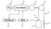
【解決手段】電力変換装置8から供給される交流電力によって駆動される巻上機5と、巻上機5によって駆動されるシーブ3と、シーブ3に巻き掛けられた主ロープ2によって吊り下げられたかご1および釣り合い錘4と、かご1内の負荷を検出してかご負荷を出力する秤装置6と、かご負荷に基づいて電力変換装置8を制御するとともに、かご負荷とかご負荷の許容最大値である最大積載量とに基づいてかご1内の乗客数を監視する制御部9と、電力変換装置8の過負荷状態を検出する過負荷検出部10とを備え、制御部9は、過負荷検出部10が過負荷状態を検出した場合に、最大積載量を、電力変換装置8の通常時における最大積載量よりも低減してかご1内の乗客数を制限する。
【選択図】図1There is provided an elevator apparatus capable of continuing operation without limiting the maximum speed or acceleration of a car even after an overload state of power conversion means is detected.
A hoisting machine 5 driven by AC power supplied from a power converter 8, a sheave 3 driven by the hoisting machine 5, and a main rope 2 wound around the sheave 3. The car 1 and the counterweight 4, the scale device 6 that detects the load in the car 1 and outputs the car load, and controls the power converter 8 based on the car load, and the maximum allowable load of the car load and the car load. A control unit 9 that monitors the number of passengers in the car 1 based on the maximum load capacity that is a value, and an overload detection unit 10 that detects an overload state of the power converter 8. When the load detection unit 10 detects an overload state, the maximum load capacity is reduced from the maximum load capacity at the normal time of the power converter 8 to limit the number of passengers in the car 1.
[Selection] Figure 1
Description
この発明は、電力変換手段から供給される交流電力によって駆動するエレベータ装置に関する。 The present invention relates to an elevator apparatus that is driven by AC power supplied from power conversion means.
従来のエレベータ装置は、かご側の重量と釣り合い錘の重量との差が大きいときよりも小さいときに、かごの最高速度および加速度を上げてかごを走行させるモータ制御部と、エレベータの異常状態(電力変換手段(インバータ)の過負荷状態等)を検出する異常検出部とを備えている。モータ制御部は、最高速度および加速度を上げてかごを走行させているときに、異常検出部が温度センサやかご負荷検出部からの信号に基づいてエレベータの異常状態を検出すると、かごを急停止させる、またはかごの最高速度を低減するといった処理を実行する(例えば、特許文献1参照)。 The conventional elevator apparatus includes a motor control unit that increases the maximum speed and acceleration of the car and causes the car to run when the difference between the weight on the car side and the weight of the counterweight is large, and the abnormal state of the elevator ( And an abnormality detection unit for detecting an overload state of the power conversion means (inverter). The motor controller stops the car abruptly when the abnormality detection unit detects an abnormal state of the elevator based on a signal from the temperature sensor or the car load detection unit while the car is running at the maximum speed and acceleration. Or a process of reducing the maximum speed of the car is performed (see, for example, Patent Document 1).
しかしながら、従来技術には、次のような問題点があった。
従来のエレベータ装置では、異常検出部がエレベータの異常状態を検出すると、モータ制御部は、例えばかごの最高速度を低減するといった処理を実行する。そのため、乗客が乗っているかごと釣り合い錘とがバランスし、電力変換手段等に余裕がある運転状態であっても、かごの最高速度や加速度が制限されるので、必要以上に輸送能力が低減され、利用者の利便性が低下するという問題があった。
However, the prior art has the following problems.
In the conventional elevator apparatus, when the abnormality detection unit detects an abnormal state of the elevator, the motor control unit executes a process of reducing the maximum speed of the car, for example. Therefore, even if the passenger is in balance with the counterweight, and even in an operating state where there is a margin in the power conversion means etc., the maximum speed and acceleration of the car are limited, so the transport capacity is reduced more than necessary. There was a problem that the convenience for the user was reduced.
この発明は、上記のような課題を解決するためになされたものであって、その目的は、電力変換手段の過負荷状態が検出された後においても、かごの最高速度や加速度を制限することなく、運転を継続することができるエレベータ装置を提供することにある。 The present invention has been made to solve the above-described problems, and its purpose is to limit the maximum speed and acceleration of the car even after the overload state of the power conversion means is detected. It is providing the elevator apparatus which can continue driving | operation.
この発明に係るエレベータ装置は、電源電力を可変電圧可変周波数の交流電力に変換する電力変換手段と、電力変換手段から供給される交流電力によって駆動される巻上機と、巻上機によって駆動されるシーブと、シーブに巻き掛けられた主ロープによって吊り下げられたかごおよび釣り合い錘と、かご内の負荷を検出してかご負荷を出力するかご内負荷検出手段と、かご負荷に基づいて電力変換手段を制御するとともに、かご負荷とかご負荷の許容最大値である最大積載量とに基づいてかご内の乗客数を監視する制御手段と、電力変換手段の過負荷状態を検出する過負荷検出手段とを備え、制御手段は、過負荷検出手段が過負荷状態を検出した場合に、最大積載量を、電力変換手段の通常時における最大積載量よりも低減してかご内の乗客数を制限する。 An elevator apparatus according to the present invention includes power conversion means for converting power supply power to AC power having variable voltage and variable frequency, a hoisting machine driven by AC power supplied from the power conversion means, and a hoisting machine. A sheave, a car and counterweight suspended by a main rope wound around the sheave, a car load detection means for detecting a car load and outputting the car load, and power conversion based on the car load Control means for controlling the means and monitoring the number of passengers in the car based on the car load and the maximum load capacity which is the maximum allowable car load, and an overload detection means for detecting the overload state of the power conversion means When the overload detection means detects an overload condition, the control means reduces the maximum load capacity from the maximum load capacity at the normal time of the power conversion means, and passengers in the car To restrict.
この発明のエレベータ装置によれば、制御手段は、過負荷検出手段が電力変換手段の過負荷状態を検出した場合に、かご負荷の許容最大値である最大積載量を、電力変換手段の通常時における最大積載量よりも低減してかご内の乗客数を制限する。これにより、電力変換手段の消費電力を制限して発熱を抑制することができる。
したがって、電力変換手段の過負荷状態が検出された後においても、かごの最高速度や加速度を制限することなく、運転を継続することができ、利用者の利便性を向上させることができる。
According to the elevator apparatus of the present invention, when the overload detection unit detects an overload state of the power conversion unit, the control unit determines the maximum load amount that is the allowable maximum value of the car load when the power conversion unit is normal. The number of passengers in the car is limited by reducing the maximum load capacity in the car. Thereby, heat consumption can be suppressed by limiting the power consumption of the power conversion means.
Therefore, even after the overload state of the power conversion means is detected, driving can be continued without limiting the maximum speed and acceleration of the car, and the convenience for the user can be improved.
以下、この発明の各実施の形態について図に基づいて説明するが、各図において同一、または相当する部分については、同一符号を付して説明する。 Hereinafter, embodiments of the present invention will be described with reference to the drawings. In the drawings, the same or corresponding parts will be described with the same reference numerals.
実施の形態1.
図1は、この発明の実施の形態1に係るエレベータ装置を示すブロック構成図である。
図1において、かご1には、主ロープ2の一端が接続されている。主ロープ2は、シーブ3に巻き掛けられ、主ロープ2の他端には、釣り合い錘4が接続されている。シーブ3は、巻上機5に接続され、巻上機5の回転駆動に応じて駆動されてかご1を昇降させる。
1 is a block diagram showing an elevator apparatus according to
In FIG. 1, one end of a main rope 2 is connected to the
また、かご1には、かご1内の負荷を検出してかご負荷を出力する秤装置6(かご内負荷検出手段)が取り付けられている。また、釣り合い錘4の重量は、一般的にかご1の定格積載量の50%の重量と釣り合うように設定されている。なお、釣り合い錘4の重量は、かご1の定格積載量の50%に限定されず、他の値であってもよい。
巻上機5は、商用電源7からの交流電力(電源電力)を可変電圧可変周波数の交流電力に変換する電力変換装置8(電力変換手段)から供給される交流電力によって駆動される。
Further, the
The hoisting
また、電力変換装置8には、秤装置6から出力されたかご負荷に基づいて、電力変換装置8を制御する制御部9(制御手段)が接続されている。具体的には、制御部9は、例えば上記特許文献1に示されているように、かご負荷に基づいて最短時間で目的階に到達するような速度パターン(最高速度および加速度)を生成し、速度パターンに応じて巻上機5を駆動させるべく、電力変換装置8を制御する。
また、制御部9は、かご負荷とかご負荷の許容最大値である最大積載量とに基づいてかご1内の乗客数を監視する。具体的には、制御部9は、かご負荷が最大積載量よりも大きくなった場合に、ブザーを鳴らして定員超過(過荷重)を報知する。
The
Further, the control unit 9 monitors the number of passengers in the
また、電力変換装置8には、電力変換装置8の過負荷状態を検出する過負荷検出部10(過負荷検出手段)が接続されている。ここで、過負荷状態とは、電力変換装置8の主回路の温度が許容温度を超えて上昇している状態とする。
過負荷検出部10は、電力変換装置8の温度検出器(後述する)から出力される温度の情報に基づいて電力変換装置8の主回路の負荷状態を監視し、過負荷状態を検出すると、制御部9に制限信号を出力する。
The
The
また、制御部9は、過負荷検出部10からの制限信号を受信すると、かご負荷の許容最大値である最大積載量を、電力変換装置8の通常時における最大積載量よりも低減してかご1内の乗客数を制限する。具体的には、制御部9は、制限信号を受信すると、電力変換装置8の通常時に例えば定格積載量の110%である最大積載量を、定格積載量の100%に低減してかご1内の乗客数を制限する。
ここで、電力変換装置8の主回路の温度上昇は、電力と比例関係にある。また、電力は、速度とトルクとの積で与えられるので、最大積載量を低減することにより、巻上機5の出力トルクを制限して電力変換装置8の消費電力を制限し、発熱を抑制することができる。
Further, when the control unit 9 receives the limit signal from the
Here, the temperature rise of the main circuit of the
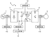
図2は、この発明の実施の形態1に係る電力変換装置8を巻上機5および商用電源7とともに詳細に示すブロック構成図である。
図2において、電力変換装置8は、コンバータ11と、平滑コンデンサ12と、インバータ13と、電流検出器14a、14b(電流検出手段)と、電圧検出器15と、スイッチ指令部16と、回生トランジスタ17と、回生抵抗18と、温度検出器19(温度検出手段)とを有している。
FIG. 2 is a block configuration diagram showing in detail the
In FIG. 2, a
コンバータ11は、商用電源7から三相交流で供給される交流電力を整流して、二相直流電力に変換する。平滑コンデンサ12は、コンバータ11からの直流電力を平滑化する。インバータ13は、平滑コンデンサ12で平滑化された直流電力を、可変電圧可変周波数の三相交流電力に変換し、巻上機5を回転駆動する。
電流検出器14aは、コンバータ11に入力される電流を検出し、電流検出器14bは、インバータ13から出力される電流を検出する。
The
なお、かご1内が無負荷であるときの上昇運転や、かご1内が満員であるときの下降運転のように、巻上機5が回生運転をする場合には、巻上機5からの回生電力がインバータ13を介して戻ってくるので、平滑コンデンサ12の両端電圧は上昇する。
電圧検出器15は、平滑コンデンサ12の両端電圧を検出し、スイッチ指令部16に出力する。スイッチ指令部16は、平滑コンデンサ12の両端電圧が所定電圧よりも大きくなると、回生トランジスタ17にオン指令を出力し、回生抵抗18により回生電力を熱エネルギーとして消費させる。
また、温度検出器19は、コンバータ11、インバータ13および回生抵抗18に接続され、各々の温度を検出する。
In addition, when the hoisting
The
Moreover, the
以下、図1、2とともに、図3のフローチャートを参照しながら、過負荷検出部10の動作について説明する。なお、このフローチャートに示される処理は、所定周期ごとに実施される。
まず、過負荷検出部10は、温度検出器19で検出されたコンバータ11の温度が、所定温度Tc以上であるか否かを判定する(ステップS21)。
ステップS21において、コンバータ11の温度が、所定温度Tcよりも低い(すなわち、No)と判定された場合には、過負荷検出部10は、温度検出器19で検出されたインバータ13の温度が、所定温度Ti以上であるか否かを判定する(ステップS22)。
Hereinafter, the operation of the
First, the
In step S21, when it is determined that the temperature of the
ステップS22において、インバータ13の温度が、所定温度Tiよりも低い(すなわち、No)と判定された場合には、過負荷検出部10は、温度検出器19で検出された回生抵抗18の温度が、所定温度Tr以上であるか否かを判定する(ステップS23)。
ステップS23において、回生抵抗18の温度が、所定温度Trよりも低い(すなわち、No)と判定された場合には、過負荷検出部10は、そのまま図3の処理を終了する。
In step S22, when it is determined that the temperature of the
In step S23, when it is determined that the temperature of the
一方、ステップS21において、コンバータ11の温度が所定温度Tc以上である(すなわち、Yes)と判定された場合、ステップS22において、インバータ13の温度が所定温度Ti以上である(すなわち、Yes)と判定された場合、およびステップS23において、回生抵抗18の温度が所定温度Tr以上である(すなわち、Yes)と判定された場合には、過負荷検出部10は、制御部9に制限信号を出力して(ステップS24)、図3の処理を終了する。
なお、温度の瞬時値による誤検出を防止するために、温度検出器19で検出された温度が所定温度以上の状態が所定時間以上継続した場合に、過負荷検出部10が過負荷状態を検出してもよい。
On the other hand, when it is determined in step S21 that the temperature of the
In order to prevent erroneous detection due to an instantaneous temperature value, the
この発明の実施の形態1に係るエレベータ装置によれば、過負荷検出部は、温度検出手段で検出された電力変換手段の温度が所定温度以上である場合に、過負荷状態を検出する。また、制御手段は、過負荷検出手段が電力変換手段の過負荷状態を検出した場合に、かご負荷の許容最大値である最大積載量を、電力変換手段の通常時における最大積載量よりも低減してかご内の乗客数を制限する。
これにより、電力変換手段の消費電力を制限して発熱を抑制することができる。
したがって、電力変換手段の過負荷状態が検出された後においても、かごの最高速度や加速度を制限することなく、運転を継続することができ、利用者の利便性を向上させることができる。
According to the elevator apparatus according to
Thereby, heat consumption can be suppressed by limiting the power consumption of the power conversion means.
Therefore, even after the overload state of the power conversion means is detected, driving can be continued without limiting the maximum speed and acceleration of the car, and the convenience for the user can be improved.
実施の形態2.
図4は、この発明の実施の形態2に係る電力変換装置8Aを巻上機5および商用電源7とともに詳細に示すブロック構成図である。
図4において、電力変換装置8Aは、温度検出器19を有していない点で図2の電力変換装置8と異なっている。また、この発明の実施の形態2に係るエレベータ装置の構成は、電力変換装置8Aを除いて、図1のものと同様である。
なお、過負荷検出部10は、電力変換装置8Aから出力される電流および電圧の情報に基づいて、コンバータ11、インバータ13および回生抵抗18の温度を推定する温度推定部を有している。
Embodiment 2. FIG.
FIG. 4 is a block configuration diagram showing in detail the
In FIG. 4, the
The
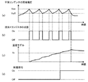
以下、図1、4とともに、図5を参照しながら、過負荷検出部10の温度推定部が回生抵抗18の温度を推定する処理について説明する。
図5において、(a)は電圧検出器15により検出される平滑コンデンサ12の両端電圧、(b)は回生トランジスタ17のスイッチ状態、(c)は温度モデル、(d)は制限信号の出力状態をそれぞれ示している。
Hereinafter, a process in which the temperature estimation unit of the
5, (a) is the voltage across the smoothing
巻上機5が回生運転をする場合には、巻上機5からの回生電力によって平滑コンデンサ12の両端電圧が増加する。平滑コンデンサ12の両端電圧がVonを超えると、スイッチ指令部16から回生トランジスタ17にオン指令が出力され、回生抵抗18により回生電力が熱エネルギーとして消費される。このとき、回生抵抗18によって電力が消費されるので、平滑コンデンサ12の両端電圧は低下する。平滑コンデンサ12の両端電圧がVoffを下回ると、スイッチ指令部16から回生トランジスタ17にオフ指令が出力される。
When the hoisting
また、温度モデルは、例えば電圧検出器15で検出された平滑コンデンサ12の両端電圧と、電流検出器14bで検出されたインバータ13から出力される電流との積を入力とした一次のローパスフィルタにより得ることができる。ここで、あらかじめ試験によってローパスフィルタの時定数を同定しておくことにより、高精度に温度を推定することができる。
Further, the temperature model is, for example, a first-order low-pass filter that receives the product of the voltage across the smoothing
過負荷検出部10は、推定した回生抵抗18の温度が所定温度Tr以上になった場合に、制御部9に制限信号を出力する。
なお、回生抵抗18の温度は、回生トランジスタ17のオン時間の割合から推定することもできるので、過負荷検出部10の温度推定部は、回生トランジスタ17のオン時間の割合が所定割合以上である場合に、過負荷状態を検出してもよい。
The
Since the temperature of the
また、過負荷検出部10の温度推定部は、電圧検出器15で検出された平滑コンデンサ12の両端電圧と、電流検出器14aで検出されたコンバータ11に入力される電流との積を入力とした一次のローパスフィルタにより、コンバータ11の温度を推定する。過負荷検出部10は、推定したコンバータ11の温度が所定温度Tc以上になった場合に、制御部9に制限信号を出力する。
Further, the temperature estimation unit of the
また、過負荷検出部10の温度推定部は、電圧検出器15で検出された平滑コンデンサ12の両端電圧と、電流検出器14bで検出されたインバータ13から出力される電流との積を入力とした一次のローパスフィルタにより、インバータ13の温度を推定する。過負荷検出部10は、推定したインバータ13の温度が所定温度Ti以上になった場合に、制御部9に制限信号を出力する。
The temperature estimation unit of the
なお、コンバータ11およびインバータ13の温度は、電流検出器14aおよび電流検出器14bで検出された電流の2乗を入力とした温度モデルによっても推定することができる。そこで、過負荷検出部10の温度推定部は、電流検出器14aおよび電流検出器14bで検出された電流が所定電流以上である場合に、過負荷状態を検出してもよい。
ここで、電流の瞬時値による誤検出を防止するために、電流検出器14aおよび電流検出器14bで検出された電流が所定電流以上の状態が所定時間以上継続した場合に、過負荷検出部10が過負荷状態を検出してもよい。
また、過負荷検出部10の温度推定部以外の動作については、実施の形態1と同様なので、その説明は省略する。
Note that the temperatures of the
Here, in order to prevent erroneous detection due to the instantaneous value of the current, when the current detected by the
Moreover, since operations other than the temperature estimation unit of the
この発明の実施の形態2に係るエレベータ装置によれば、過負荷検出部は、電流検出手段で検出された電流および電圧検出器15で検出された電圧に基づいて、電力変換手段の温度を推定し、過負荷状態を検出する。
また、過負荷検出部は、電流検出手段で検出された電流が所定電流以上である場合に、過負荷状態を検出する。また、過負荷検出部は、回生トランジスタのオン時間の割合が所定割合以上である場合に、過負荷状態を検出する。
そのため、温度検出手段をさらに設ける必要がないので、コストダウンを実現することができる。
According to the elevator apparatus according to Embodiment 2 of the present invention, the overload detection unit estimates the temperature of the power conversion unit based on the current detected by the current detection unit and the voltage detected by the
The overload detection unit detects an overload state when the current detected by the current detection unit is equal to or greater than a predetermined current. The overload detection unit detects an overload state when the on-time ratio of the regenerative transistor is equal to or greater than a predetermined ratio.
For this reason, it is not necessary to further provide a temperature detecting means, so that cost reduction can be realized.
なお、上記実施の形態1、2において、制御部9は、電力変換装置8の過負荷状態が検出されたときに、かご負荷の許容最大値である最大積載量を低減すると説明したが、これに限定されない。制御部9は、電力変換装置8が過負荷状態に至る前から徐々に最大積載量を低減してもよい。すなわち、例えば回生抵抗18について、所定温度Trよりも低温の箇所に別の閾値を設定し、回生抵抗18の温度がその閾値を超えた場合に、制御部9が最大積載量を定格積載量の110%から例えば定格積載量の105%に低減してもよい。また、複数の閾値を設定して最大積載量を複数段階で低減してもよい。
この場合には、電力変換装置8の消費電力を制限して発熱を抑制することができ、電力変換装置8が過負荷状態に陥ることを防止することができる。
In the first and second embodiments described above, the control unit 9 has been described to reduce the maximum load capacity that is the allowable maximum value of the car load when the overload state of the
In this case, the power consumption of the
1 かご、2 主ロープ、3 シーブ、4 釣り合い錘、5 巻上機、6 秤装置(かご内負荷検出手段)、7 商用電源、8、8A 電力変換装置(電力変換手段)、9 制御部(制御手段)、10 過負荷検出部(過負荷検出手段)、11 コンバータ、12 平滑コンデンサ、13 インバータ、14a、14b 電流検出器(電流検出手段)、15 電圧検出器、16 スイッチ指令部、17 回生トランジスタ、18 回生抵抗、19 温度検出器(温度検出手段)。 1 car, 2 main ropes, 3 sheaves, 4 counterweights, 5 hoisting machine, 6 scale device (cage load detection means), 7 commercial power supply, 8, 8A power conversion device (power conversion means), 9 control unit ( Control means), 10 overload detection part (overload detection means), 11 converter, 12 smoothing capacitor, 13 inverter, 14a, 14b current detector (current detection means), 15 voltage detector, 16 switch command part, 17 regeneration Transistor, 18 regenerative resistor, 19 Temperature detector (temperature detection means).
Claims (4)
前記電力変換手段から供給される交流電力によって駆動される巻上機と、
前記巻上機によって駆動されるシーブと、
前記シーブに巻き掛けられた主ロープによって吊り下げられたかごおよび釣り合い錘と、
前記かご内の負荷を検出してかご負荷を出力するかご内負荷検出手段と、
前記かご負荷に基づいて前記電力変換手段を制御するとともに、前記かご負荷とかご負荷の許容最大値である最大積載量とに基づいて前記かご内の乗客数を監視する制御手段と、
前記電力変換手段の過負荷状態を検出する過負荷検出手段と、を備え、
前記制御手段は、前記過負荷検出手段が前記過負荷状態を検出した場合に、前記最大積載量を、前記電力変換手段の通常時における最大積載量よりも低減して前記かご内の乗客数を制限することを特徴とするエレベータ装置。 Power conversion means for converting power supply power to AC power of variable voltage and variable frequency;
A hoisting machine driven by AC power supplied from the power conversion means;
A sheave driven by the hoist,
A cage and a counterweight suspended by a main rope wound around the sheave;
An in-car load detecting means for detecting the load in the car and outputting the car load;
Control means for controlling the power conversion means based on the car load, and for monitoring the number of passengers in the car based on the car load and a maximum load capacity that is an allowable maximum value of the car load;
Overload detection means for detecting an overload state of the power conversion means,
The control means, when the overload detection means detects the overload state, reduces the maximum load capacity from the maximum load capacity at the normal time of the power conversion means to reduce the number of passengers in the car. The elevator apparatus characterized by restricting.
前記過負荷検出手段は、前記温度検出手段で検出された温度が所定温度以上である場合に、前記過負荷状態を検出することを特徴とする請求項1に記載のエレベータ装置。 Temperature detection means for detecting the temperature of the power conversion means,
The elevator apparatus according to claim 1, wherein the overload detection unit detects the overload state when a temperature detected by the temperature detection unit is equal to or higher than a predetermined temperature.
前記過負荷検出手段は、前記電流検出手段で検出された電流が所定電流以上である場合に、前記過負荷状態を検出することを特徴とする請求項1に記載のエレベータ装置。 A current detection means for detecting a current flowing through the power conversion means;
The elevator apparatus according to claim 1, wherein the overload detection unit detects the overload state when the current detected by the current detection unit is equal to or greater than a predetermined current.
前記過負荷検出手段は、前記回生トランジスタのオン時間の割合が所定割合以上である場合に、前記過負荷状態を検出することを特徴とする請求項1に記載のエレベータ装置。 The power conversion means includes a regenerative resistor that consumes power regenerated during regenerative operation of the hoist as heat, and a regenerative transistor that controls on / off of a current flowing through the regenerative resistor,
2. The elevator apparatus according to claim 1, wherein the overload detection unit detects the overload state when an on-time ratio of the regenerative transistor is equal to or greater than a predetermined ratio.
Priority Applications (1)
| Application Number | Priority Date | Filing Date | Title |
|---|---|---|---|
| JP2008321514A JP2010143692A (en) | 2008-12-17 | 2008-12-17 | Elevator device |
Applications Claiming Priority (1)
| Application Number | Priority Date | Filing Date | Title |
|---|---|---|---|
| JP2008321514A JP2010143692A (en) | 2008-12-17 | 2008-12-17 | Elevator device |
Publications (1)
| Publication Number | Publication Date |
|---|---|
| JP2010143692A true JP2010143692A (en) | 2010-07-01 |
Family
ID=42564525
Family Applications (1)
| Application Number | Title | Priority Date | Filing Date |
|---|---|---|---|
| JP2008321514A Pending JP2010143692A (en) | 2008-12-17 | 2008-12-17 | Elevator device |
Country Status (1)
| Country | Link |
|---|---|
| JP (1) | JP2010143692A (en) |
Cited By (5)
| Publication number | Priority date | Publication date | Assignee | Title |
|---|---|---|---|---|
| CN102674099A (en) * | 2011-03-09 | 2012-09-19 | 东芝电梯株式会社 | Elevator system |
| CN102774720A (en) * | 2012-08-16 | 2012-11-14 | 哈尔滨市机电类特种设备监督检验研究院 | Elevator overload protection method |
| WO2015063722A1 (en) | 2013-11-01 | 2015-05-07 | Kone Corporation | Elevator and method for the use of an elevator control system in monitoring the load of a car and/or to determine the load situation |
| WO2016053018A3 (en) * | 2014-10-01 | 2016-05-26 | 한국미쓰비시엘리베이터 주식회사 | Elevator apparatus |
| WO2018003014A1 (en) * | 2016-06-28 | 2018-01-04 | 三菱電機株式会社 | Elevator system |
Citations (4)
| Publication number | Priority date | Publication date | Assignee | Title |
|---|---|---|---|---|
| JPH09227038A (en) * | 1996-02-27 | 1997-09-02 | Toshiba Corp | Linear motor |
| JP2002003091A (en) * | 2000-06-22 | 2002-01-09 | Toshiba Fa Syst Eng Corp | Elevator control system |
| JP2002060147A (en) * | 2000-08-18 | 2002-02-26 | Mitsubishi Electric Corp | Elevator control device |
| WO2007013448A1 (en) * | 2005-07-26 | 2007-02-01 | Mitsubishi Electric Corporation | Elevator device |
-
2008
- 2008-12-17 JP JP2008321514A patent/JP2010143692A/en active Pending
Patent Citations (4)
| Publication number | Priority date | Publication date | Assignee | Title |
|---|---|---|---|---|
| JPH09227038A (en) * | 1996-02-27 | 1997-09-02 | Toshiba Corp | Linear motor |
| JP2002003091A (en) * | 2000-06-22 | 2002-01-09 | Toshiba Fa Syst Eng Corp | Elevator control system |
| JP2002060147A (en) * | 2000-08-18 | 2002-02-26 | Mitsubishi Electric Corp | Elevator control device |
| WO2007013448A1 (en) * | 2005-07-26 | 2007-02-01 | Mitsubishi Electric Corporation | Elevator device |
Cited By (9)
| Publication number | Priority date | Publication date | Assignee | Title |
|---|---|---|---|---|
| CN102674099A (en) * | 2011-03-09 | 2012-09-19 | 东芝电梯株式会社 | Elevator system |
| CN102774720A (en) * | 2012-08-16 | 2012-11-14 | 哈尔滨市机电类特种设备监督检验研究院 | Elevator overload protection method |
| CN102774720B (en) * | 2012-08-16 | 2016-09-14 | 哈尔滨市机电类特种设备监督检验研究院 | Elevator overload protection method |
| WO2015063722A1 (en) | 2013-11-01 | 2015-05-07 | Kone Corporation | Elevator and method for the use of an elevator control system in monitoring the load of a car and/or to determine the load situation |
| CN105683079A (en) * | 2013-11-01 | 2016-06-15 | 通力股份公司 | Elevator and method for the use of an elevator control system in monitoring the load of a car and/or to determine the load situation |
| CN105683079B (en) * | 2013-11-01 | 2018-01-12 | 通力股份公司 | For the elevator and method using apparatus for controlling elevator monitoring car load and/or determination loading condition |
| US10179718B2 (en) | 2013-11-01 | 2019-01-15 | Kone Corporation | Elevator car overload monitoring to prevent starting |
| WO2016053018A3 (en) * | 2014-10-01 | 2016-05-26 | 한국미쓰비시엘리베이터 주식회사 | Elevator apparatus |
| WO2018003014A1 (en) * | 2016-06-28 | 2018-01-04 | 三菱電機株式会社 | Elevator system |
Similar Documents
| Publication | Publication Date | Title |
|---|---|---|
| US7931128B2 (en) | Elevator device | |
| US8348020B2 (en) | Elevator control device with carrier frequency switch circuit | |
| JP6237474B2 (en) | Elevator car movement control device and car movement control method | |
| JP2001240319A (en) | Elevator control device | |
| US7882937B2 (en) | Elevating machine control apparatus | |
| JP4896992B2 (en) | Elevator control device | |
| JP5557815B2 (en) | Energy saving elevator | |
| JP2010143692A (en) | Elevator device | |
| JP5241367B2 (en) | Electric hoist | |
| JP2010168154A (en) | Control device for elevator | |
| JP2005324879A (en) | Elevator control device | |
| JP2005126171A (en) | Elevator power failure operation device | |
| SG191508A1 (en) | Drive apparatus of elevator apparatus | |
| JP2005280935A (en) | Elevator control device | |
| JP4663849B2 (en) | Elevator control device | |
| JP2007153574A (en) | Elevator equipment | |
| JP2013023319A (en) | Control device of hybrid drive type elevator | |
| JP2011195279A (en) | Control device of elevator | |
| JP6704518B2 (en) | Elevator control equipment | |
| JP4619039B2 (en) | Elevator control device | |
| JP2007238300A (en) | Elevator | |
| JP2005324880A (en) | Elevator control device | |
| CN105228938B (en) | Elevator control system | |
| JP5095223B2 (en) | Elevator equipment | |
| JP2012144357A (en) | Elevator |
Legal Events
| Date | Code | Title | Description |
|---|---|---|---|
| A621 | Written request for application examination |
Effective date: 20110802 Free format text: JAPANESE INTERMEDIATE CODE: A621 |
|
| A977 | Report on retrieval |
Effective date: 20121218 Free format text: JAPANESE INTERMEDIATE CODE: A971007 |
|
| A131 | Notification of reasons for refusal |
Effective date: 20121225 Free format text: JAPANESE INTERMEDIATE CODE: A131 |
|
| A521 | Written amendment |
Effective date: 20130222 Free format text: JAPANESE INTERMEDIATE CODE: A523 |
|
| A131 | Notification of reasons for refusal |
Effective date: 20130903 Free format text: JAPANESE INTERMEDIATE CODE: A131 |
|
| A02 | Decision of refusal |
Free format text: JAPANESE INTERMEDIATE CODE: A02 Effective date: 20140107 |