EP2005872B1 - Sanitary cleansing apparatus - Google Patents
Sanitary cleansing apparatus Download PDFInfo
- Publication number
- EP2005872B1 EP2005872B1 EP07714104.2A EP07714104A EP2005872B1 EP 2005872 B1 EP2005872 B1 EP 2005872B1 EP 07714104 A EP07714104 A EP 07714104A EP 2005872 B1 EP2005872 B1 EP 2005872B1
- Authority
- EP
- European Patent Office
- Prior art keywords
- toilet lid
- toilet
- main body
- transmissive window
- opening
- Prior art date
- Legal status (The legal status is an assumption and is not a legal conclusion. Google has not performed a legal analysis and makes no representation as to the accuracy of the status listed.)
- Active
Links
Images


Classifications
-
- A—HUMAN NECESSITIES
- A47—FURNITURE; DOMESTIC ARTICLES OR APPLIANCES; COFFEE MILLS; SPICE MILLS; SUCTION CLEANERS IN GENERAL
- A47K—SANITARY EQUIPMENT NOT OTHERWISE PROVIDED FOR; TOILET ACCESSORIES
- A47K13/00—Seats or covers for all kinds of closets
- A47K13/14—Protecting covers for closet seats
-
- A—HUMAN NECESSITIES
- A47—FURNITURE; DOMESTIC ARTICLES OR APPLIANCES; COFFEE MILLS; SPICE MILLS; SUCTION CLEANERS IN GENERAL
- A47K—SANITARY EQUIPMENT NOT OTHERWISE PROVIDED FOR; TOILET ACCESSORIES
- A47K13/00—Seats or covers for all kinds of closets
- A47K13/24—Parts or details not covered in, or of interest apart from, groups A47K13/02 - A47K13/22, e.g. devices imparting a swinging or vibrating motion to the seats
- A47K13/30—Seats having provisions for heating, deodorising or the like, e.g. ventilating, noise-damping or cleaning devices
- A47K13/302—Seats with cleaning devices
-
- E—FIXED CONSTRUCTIONS
- E03—WATER SUPPLY; SEWERAGE
- E03D—WATER-CLOSETS OR URINALS WITH FLUSHING DEVICES; FLUSHING VALVES THEREFOR
- E03D5/00—Special constructions of flushing devices, e.g. closed flushing system
- E03D5/10—Special constructions of flushing devices, e.g. closed flushing system operated electrically, e.g. by a photo-cell; also combined with devices for opening or closing shutters in the bowl outlet and/or with devices for raising/or lowering seat and cover and/or for swiveling the bowl
- E03D5/105—Special constructions of flushing devices, e.g. closed flushing system operated electrically, e.g. by a photo-cell; also combined with devices for opening or closing shutters in the bowl outlet and/or with devices for raising/or lowering seat and cover and/or for swiveling the bowl touchless, e.g. using sensors
-
- E—FIXED CONSTRUCTIONS
- E03—WATER SUPPLY; SEWERAGE
- E03D—WATER-CLOSETS OR URINALS WITH FLUSHING DEVICES; FLUSHING VALVES THEREFOR
- E03D9/00—Sanitary or other accessories for lavatories ; Devices for cleaning or disinfecting the toilet room or the toilet bowl; Devices for eliminating smells
- E03D9/08—Devices in the bowl producing upwardly-directed sprays; Modifications of the bowl for use with such devices ; Bidets; Combinations of bowls with urinals or bidets; Hot-air or other devices mounted in or on the bowl, urinal or bidet for cleaning or disinfecting
Definitions
- This invention relates to a sanitary cleansing apparatus and a toilet apparatus, and more particularly to a sanitary cleansing apparatus provided with a reclosable toilet lid and a toilet.
- a sanitary cleansing apparatus retractably houses therein a water discharge nozzle for squirting wash water.
- the sanitary cleansing apparatus is placed on a sit-down toilet bowl so that the user's "bottom" can be cleansed with warm water.
- a toilet seat allowing a user to sit thereon and a toilet lid covering it are reclosably and pivotally supported on the sanitary cleansing apparatus (e.g., Patent Documents 1 and 2).
- sanitary cleansing apparatuses include a human body detection sensor for detecting the access or presence of a user.
- the toilet lid can be automatically opened/closed, the toilet bowl can be automatically flushed with wash water, and the temperature of the toilet seat and wash water can be controlled.
- Patent Document 3 JP 1-270831A (1989 )
- JP 2003 235761 describes a toilet lid with a light transmissive part.
- the toilet lid in its closed state covers not only the toilet seat but also the main body of the sanitary cleansing apparatus, a sleek appearance is achieved. Furthermore, the toilet lid eliminates gaps through which dust may intrude. Moreover, the toilet lid can improve cleanability in wipe and other cleaning.
- the toilet lid covering up to the main body of the sanitary cleansing apparatus causes a problem of shielding light in the detection range of an infrared transmission human body detection sensor.
- the human body detection sensor needs to be projected laterally from the sanitary cleansing apparatus, or to be exposed by providing a notch at the rear of the toilet lid.
- such configuration contrarily deteriorates the appearance and decreases the cleanability of the sanitary cleansing apparatus.
- the open-end angle, or maximum opening angle, of the toilet lid is widely varied depending on the installation site. More specifically, in the case of a toilet of the low-tank type, a low tank is located behind the toilet lid. In the case of a toilet of the service-water direct-pressure type without a low tank, a shelf or bay window of the toilet may be located behind the toilet bowl.
- This invention provides a sanitary cleansing apparatus that can be substantially entirely covered with a toilet lid and that can also reliably perform human body detection, and a toilet apparatus provided therewith.
- this invention provides a toilet seat apparatus capable of preventing collision with an object therebehind at the time of opening the toilet lid, and a toilet apparatus provided therewith.
- a sanitary cleansing apparatus as recited in claim 1.
- FIGS. 1 and 2 are schematic perspective views of a toilet apparatus equipped with a sanitary cleansing apparatus according to the embodiment of the invention.
- FIG. 3 is a perspective view of the sanitary cleansing apparatus of this example as viewed from the front.
- a sanitary cleansing apparatus 100 is placed on a sit-down toilet bowl 800.
- the sanitary cleansing apparatus 100 comprises a main body 400, and a toilet seat 200 and a toilet lid 300 reclosably and pivotally supported on the main body 400.
- a water discharge nozzle (not shown) extends out into the bowl of the toilet bowl 800 in response to user's switch manipulation and squirts water from a water discharge port provided near its tip so that the user's "bottom” can be cleansed.
- water used herein includes not only cold water but also heated warm water.
- the main body 400 is suitably provided with various mechanisms such as a "deodorizing unit", “warm air unit", and “room heating unit”.
- An exhaust port 440 and an ejection hole 450 are suitably provided on the side face of the main body 400. The internal configuration of the main body 400 is described later in detail.
- the toilet seat 200 is pivotally supported on the main body 400 relatively anteriorly, whereas the toilet lid 300 is pivotally supported on the main body 400 relatively posteriorly. That is, the rotary shaft of the toilet seat 200 is spaced longitudinally from the rotary shaft of the toilet lid 300.
- FIGS. 1 and 3 in the opened state of the toilet lid 300, the main body 400 and the toilet seat 200 are exposed nearly completely, and a user can sit on the toilet seat 200 without interfering with the toilet lid 300.
- the toilet lid 300 can be distanced from the user sitting on the toilet seat 200. Consequently, this allows a user sitting on the toilet seat 200 to experience a feeling of openness and to enjoy comfortable use.
- the jacket or dress is less prone to contact with the toilet lid 300, and the user is free from a feeling of oppression or sanitary discomfort.
- the toilet lid 300 when the toilet lid 300 is closed, the toilet lid 300 nearly completely covers not only the toilet seat 200 but also the main body 400. If the sanitary cleansing apparatus is nearly entirely covered with the toilet lid 300 in this manner, a very smart, simple, and a sleek appearance is achieved. By entirely covering the sanitary cleansing apparatus 100 with the toilet lid 300, no dirt or dust accumulates on the main body 400 as well as on the toilet seat 200 while not in use. Furthermore, in the closed state of the toilet lid 300, the upper face of the sanitary cleansing apparatus 100 has no "gaps" and "irregularities". Hence, in wipe cleaning with a damp cloth, the entire upper face of the toilet lid 300 can be smoothly and quickly wiped, achieving good cleanability.
- a step 405 (see also FIG. 5 ) is formed on the side face of the main body 400.
- the step 405 fits the rear lower edge 305 of the toilet lid 300 in abutment or proximity, and the side face of the main body 400 and the side face of the toilet lid 300 form a nearly continuous common surface. Consequently, in the closed state of the toilet lid 300, a continuous plane extending from the toilet lid 300 to the main body 400 is formed also on the side face of the sanitary cleansing apparatus 100. This further makes the appearance sleek and also prevents accumulation of dust and dirt. Furthermore, in the closed state of the toilet lid 300, the side face of the sanitary cleansing apparatus 100 can be wipe cleaned smoothly and quickly without causing a damp cloth to get stuck.
- the main body 400 of the sanitary cleansing apparatus of this embodiment has an upper face between the pivotal support of the toilet seat 200 and the pivotal support of the toilet lid 300, the upper face being generally parallel to the toilet lid 300 in the closed state.
- a human body detection sensor 500 is provided in the upper face.
- a transmissive window 310 is provided at the rear of the toilet lid 300.
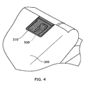
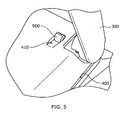
- FIGS. 4 to 6 are enlarged perspective views showing the installation portion of the human body detection sensor 500, where FIG. 4 shows the closed state of the toilet lid 300 and FIGS. 5 and 6 show the opened state of the toilet lid 300.
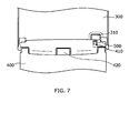
- FIG. 7 is an enlarged perspective view of the pivotal support of the toilet lid 300 in its opened state as viewed from the front.
- a recessed portion 410 is formed in the upper face of the main body 400, and the human body detection sensor 500 is provided so that a portion thereof is embedded in the recessed portion 410.
- the human body detection sensor 500 can be an infrared detection sensor.
- a pyroelectric sensor can be used to detect the presence of a user with high accuracy. It is known that the pyroelectric sensor can detect movement of a heat-generating body within a prescribed detection range in front thereof.
- the human body detection sensor 500 detects the presence of a user located in front of the sanitary cleansing apparatus through the transmissive window 310. That is, the transmissive window 310 transmits infrared radiation to be detected by the human body detection sensor 500.
- the transmissive window 310 transmits infrared radiation to be detected by the human body detection sensor 500.
- the transmissive window 310 is made of a material having a certain transmissivity for infrared radiation in this wavelength band.
- polyethylene for example, as the material of the transmissive window 310, the access or presence of a user can be detected through the transmissive window 310 with high sensitivity even in the closed state of the toilet lid 300.
- the toilet lid 300 supporting the transmissive window 310 can be formed from a material having a lower transmissivity for infrared radiation than the transmissive window 310. If the toilet lid 300 is formed from a harder and more robust material than the transmissive window 310, the toilet lid 300 has a small deflection and deformation and is less susceptible to scratches. Furthermore, the color of the toilet lid 300 can be freely chosen and easily adapted to the color of the toilet bowl 800 and the main body 400. An example material of the toilet lid 300 satisfying these requirements is polypropylene.
- the toilet lid 300 In the closed state of the toilet lid 300, when the human body detection sensor 500 detects a user, the toilet lid 300 can be automatically opened by, for example, activating a toilet lid opening/closing unit incorporated in the main body 400. Furthermore, it is possible to perform processes such as rapidly heating the toilet seat 200, warming the toilet by activating a room heating unit provided in the main body 400, and preventing the attachment of dirt by previously flushing the toilet bowl 800 with a small amount of wash water to wet the bowl.
- the human body detection sensor 500 can directly detect the presence of a user.
- the main body 400 is provided with a seating sensor 420, enabling detection of the presence of a user sitting on the toilet seat 200.
- the seating sensor 420 can be an infrared sensor operable to emit infrared radiation and to detect the reflected light intensity, for example.
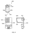
- FIG. 8 is a schematic view illustrating the structure of the human body detection sensor 500. More specifically, FIG. 8 shows the structure using a pyroelectric sensor as the human body detection sensor 500.
- the pyroelectric sensor includes a pyroelectric element 510 mounted on a substrate 530 and a lens 520 opposed to the light receiving surface of the pyroelectric element 510.
- the pyroelectric element 510 is illustratively made of a pyroelectric material based on PZT (lead zirconate titanate), LiTaO 3 (lithium tantalate), or PbTaO 3 (lead tantalate), and partitioned into a plurality of detection regions.
- the lens 520 is also partitioned into a plurality of lens portions 520L.
- FIG. 9 is a partially enlarged vertical cross-sectional view of the main body 400 with the human body detection sensor 500 embedded therein.
- the human body detection sensor 500 is provided in proximity to the rear of the case cover 430 on the upper face of the main body 400, that is, to the pivotal support of the toilet lid 300, so as to slightly protrude from the upper face of the main body 400.
- the distance between the transmissive window 310 and the human body detection sensor 500 can be reduced. Consequently, a wide range can be detected while downsizing the transmissive window 310. That is, a wide-angle range can be detected through the small transmissive window 310 as viewed from the human body detection sensor 500.
- the transmissive window 310 needs to be formed from a material having a higher transmissivity for infrared radiation than the toilet lid 300.
- the transmissive window 310 may be different in color and texture from the toilet lid 300, or may be susceptible to deformations and scratches due to low hardness. Even in such cases, according to this embodiment, the transmissive window 310 can be downsized and provided near the rear edge of the toilet lid 300. Hence the transmissive window 310 is obscured, and the effect of preventing deformation and scratching is also achieved because it is less prone to being touched by hands.
- a wide angle can be detected without significantly projecting the human body detection sensor 500 from the upper face of the case cover 430 of the main body. That is, human body detection can be reliably performed while maintaining cleanability of the upper face of the case cover 430.
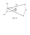
- FIGS. 10 and 11 are schematic views illustrating the range where a human body can be detected by the human body detection sensor 500 in the sanitary cleansing apparatus 100 of this example. More specifically, FIGS. 10 and 11 show horizontal and vertical detectable ranges, respectively.
- the human body detection sensor 500 can detect a human body 920 within a horizontal range of 40 degrees.
- a human body 920 located in upper front of the sanitary cleansing apparatus can be detected within a vertical range of 33 degrees. These ranges are sufficient for detecting the presence of a user approaching the sanitary cleansing apparatus 100 or a user standing in front of the sanitary cleansing apparatus 100 in a standard-sized toilet.
- an adult 920 of ordinary stature can be detected when he/she comes to a distance of 2.5 meters from the rear edge of the toilet bowl 800.
- the head of an adult 920 of ordinary stature can be also detected when he/she stands directly in front of the toilet bowl 800.
- a child 910 a little less than one meter tall being able to use a toilet alone can be detected when he/she comes to approximately 100 millimeters from the front edge of the sanitary cleansing apparatus 100.
- the head of the child 910 standing directly in front of the toilet bowl 800 can be also detected. That is, the presence of users ranging from adults to children using the toilet bowl 800 (sanitary cleansing apparatus 100) can be reliably detected.
- transmissive window 310 and its installation structure used in this example are described in more detail.
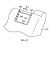
- FIG. 12 is a perspective view showing the installation portion of the toilet lid 300 where the transmissive window 310 is installed.
- an opening 340 for installing the transmissive window 310 is formed.
- Laminated rails 350 are provided on the front, left, and right sidewall of the opening 340.
- a support bridge 360 is provided at the rear edge of the opening 340.
- the transmissive window 310 is slidably inserted from the rear side of the toilet lid 300 and passed above the support bridge 360 along the rails 350 in the direction of arrow A.
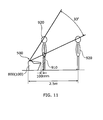
- FIG. 13 is a perspective view of the transmissive window 310 as viewed from obliquely above.
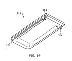
- FIG. 14 is a perspective view of the transmissive window 310 as viewed from obliquely below.
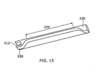
- FIG. 15 is a cross-sectional perspective view of the transmissive window 310 cut horizontally.
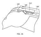
- FIG. 16 is an enlarged cross-sectional view showing a cross section of the installation portion of the transmissive window 310.
- the transmissive window 310 On the front, left, and right side face of the transmissive window 310, rail grooves 312 to engage with the rails 350 of the toilet lid 300 are provided. As shown by arrow A in FIGS. 12 and 13 , the transmissive window 310 can be installed so as to occlude the opening 340 by being slid forward from the rear edge of the toilet lid 300 while engaging the rail grooves 312 with the rails 350 on both lateral edges. When the transmissive window 310 is slid to the front edge, the rail groove 312 on its front edge engages with the rail 350 on the front edge of the opening 340.
- the upper face of the transmissive window 310 becomes continuous with the upper face of the toilet lid 300 so that "steps” or “seams” therebetween almost vanish. A sleek appearance is achieved, allowing smooth wipe cleaning.
- rails 350 are provided on the sidewalls of the opening 340, and rail grooves 312 are provided on the side faces of the transmissive window 310.
- the invention is not limited thereto.
- hooks (engaging protrusions) 314 are provided at both ends on the backside of the rear of the transmissive window 310.
- the hook 314 is formed like a claw, and is capable of vertical elastic deformation because a portion of the rail groove 312 is cut out.
- hooking recesses (engaging recesses) 365 are provided at both ends of the support bridge 360 of the toilet lid 300.
- the transmissive window 310 installed on the toilet lid 300 is pulled rearward with a force of a prescribed level or more, the hook 314 is elastically retracted and disengaged from the hooking recess 365. Hence the transmissive window 310 can be slid rearward along the rails 350 and pulled out from the toilet lid 300. Thus, when the transmissive window 310 is broken or soiled, it can be easily removed from the toilet lid 300 and replaced, serving convenience and also improving economy.
- the hook 314 is scarcely seen from the user even in the opened state of the toilet lid 300.
- the appearance can be made sleek.
- hooks (engaging protrusions) 314 are provided on the transmissive window 310, and hooking recesses (engaging recesses) 365 are provided on the support bridge 360.
- the invention is not limited thereto.
- hooking recesses engaging recesses
- hooks engaging protrusions
- the human body detection sensor 500 detects the presence of a user through the transmissive window 310.
- the transmissive window 310 has a structure transmitting infrared radiation as much as possible.
- polyethylene for example, is used as the material of the transmissive window 310 as described above.
- a thin window portion 320 is provided to increase infrared transmissivity, and a thick flange portion 330 is provided therearound for support and reinforcement.
- transmissive window 310 formed from high-density polyethylene
- the window portion 320 is thinned to a thickness of approximately 0.5 millimeters
- a sufficient detection sensitivity is achieved even in the case of using a pyroelectric sensor as the human body detection sensor 500.
- the flange portion 330 provided around the window portion 320 has a thickness of approximately 1.5 millimeters, the transmissive window 310 can be prevented from disengagement and breakage under normal conditions of use.
- the human body detection sensor 500 is protrusively provided below the transmissive window 310.
- the spacing S between the upper end of the case cover 430 and the transmissive window 310 is approximately 1 millimeter.
- the transmissive window 310 can be prevented from breakage and disengagement.
- the transmissive window 310 and its installation portion in this example have been described in detail.
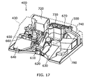
- FIG. 17 is a perspective view of the inside of the main body 400 as viewed from the front.
- FIG. 18 is a perspective view of the inside of the main body 400 as viewed from the rear.
- a display portion 670 is suitably provided near the human body detection sensor 500.
- the display portion 670 serves to suitably display the power on/off state of the toilet apparatus, for example.
- a toilet seat opening/closing unit 780 for automatically opening/closing the toilet seat 200 is protrusively provided at the upper front of the case cover 430.
- a nozzle unit 610, a warm air unit 620, and a deodorizing unit 630 are juxtaposed at the inner front of the case cover 430.
- the nozzle unit 610 includes a retractable water discharge nozzle, serving to cleanse the "bottom" of a user sitting on the toilet seat 200 by squirting water thereto.
- the warm air unit 620 serves to dry the "bottom” of a user sitting on the toilet seat 200 by applying warm air thereto.
- the deodorizing unit 630 serves to suck air in the bowl of the toilet bowl 800, to deodorize it, and to eject it from the exhaust port 440.
- An AC (alternating current) controller 640 is provided at the inner front of the case cover 430, and a pump unit 650 and a heat exchange unit 660 are provided at the rear thereof.
- the water supplied to the heat exchange unit 660 is heated therein.
- the pump unit 650 imparts pulsation to the water and supplies the pulsating water to the nozzle unit 610.
- An auxiliary control unit 680 is provided on the side face of the case cover 430.
- the auxiliary control unit 680 has a switch for operations such as cleansing the "bottom" by the nozzle unit 610, ensuring that the operation of the sanitary cleansing apparatus 100 is controllable even in the state that does not allow control by a remote controller (not shown).
- a valve unit 690 is provided at the lower rear of the case cover 430. The valve unit 690 serves to control supply of water supplied from running water to the pump unit 650.
- a DC (direct current) controller 700 and a driver unit 710 are juxtaposed at the inner upper front of the case cover 430.
- a toilet lid opening/closing unit 720 and a toilet bowl washing valve unit 730 are juxtaposed at the inner rear of the case cover 430.
- the toilet lid opening/closing unit 720 serves to open/close the toilet lid 300.
- the toilet bowl washing valve unit 730 serves to control supply of wash water used for flushing the toilet bowl 800. That is, the toilet apparatus of this example has a structure of the so-called "service-water direct-pressure type", which performs washing by supplying the water supplied from running water to the toilet bowl 800 through the toilet bowl washing valve unit 730 without the intermediary of a low tank.
- a room heating unit 740 is provided at the inner rearmost of the case cover 430.
- the room heating unit 740 serves to heat the toilet space equipped with the toilet apparatus by ejecting warm air from the ejection hole 450.
- a power cord for externally supplying power such as AC 100 V.
- FIG. 19 is a perspective view for illustrating the installation structure of the toilet bowl washing valve unit 730.
- FIG. 20 is a schematic view of the installation portion of the toilet bowl washing valve unit 730 as viewed from above.
- the toilet bowl washing valve unit 730 is supported by a toilet bowl side baseplate 760 fixed behind the toilet bowl 800, and is connected to the toilet bowl 800 through a feedwater piping 735.
- the installation board 770 of the main body 400 is fixed to the upper face of the toilet bowl 800.
- the toilet bowl washing valve unit 730 passes through an opening 775 provided in the installation board 770 and protrudes thereabove.
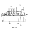
- FIG. 21 is a perspective view showing the positional relationship between the toilet lid opening/closing unit 720 and the toilet bowl washing valve unit 730.
- FIG. 22 is a schematic view of these elements as viewed from behind.
- the toilet lid opening/closing unit 720 is screwed on a plurality of pins 772 provided upright on the installation board 770.
- the toilet lid opening/closing unit 720 is spaced from the installation board 770, and the feedwater piping 735 is placed in that space. That is, the toilet lid opening/closing unit 720 is installed so as to straddle one pipe of the feedwater piping 735 of the toilet bowl washing valve unit 730.
- the toilet lid opening/closing unit 720 and the toilet bowl washing valve unit 730 are placed adjacent to each other at the rear of the main body 400.
- the functional components of the toilet apparatus 100 such as the nozzle unit 610 are suitably placed at the front of the installation board 770 and below the toilet lid opening/closing unit 720.
- the toilet apparatus of this example includes a plurality of units having various functions.
- the nozzle unit 610, warm air unit 620, deodorizing unit 630, pump unit 650, heat exchange unit 660, and valve unit 690 are provided below the main body 400.
- the toilet bowl washing valve unit 730 is internally installed at the rear of the main body 400, and the toilet lid opening/closing unit 720 is provided adjacent thereto at the rear of the main body 400.
- the toilet lid 300 can be pivotally supported at the rear of the main body 400 so as to cover generally entirely the upper face of the main body 400 when the toilet lid 300 is closed. Because the toilet lid opening/closing unit 720 is lifted above the installation board 770 by the pins 772 to accommodate therebelow the feedwater piping 735 connected to the toilet bowl washing valve unit 730, the limited space can be effectively used.
- the toilet bowl washing valve unit 730 may be provided with a plurality of long legs and installed on the installation board 770.
- the toilet bowl washing valve unit 730 is internally installed at the rear of the main body 400, and the human body detection sensor 500 is provided thereabove.
- the human body detection sensor 500 can be placed on the upper face of the main body 400 with the size of the main body 400 made compact, and as described above with reference to FIGS. 9 to 11 , a wide range can be reliably detected through a small transmissive window 310.
- the same advantageous effect can be achieved by providing the human body detection sensor 500 above the toilet lid opening/closing unit 720 rather than above the toilet bowl washing valve unit 730.
- FIG. 23 shows schematic views of the toilet seat apparatus as viewed laterally.
- the center of gravity G of the toilet lid 300 is located on the closed side of the vertically upward direction above its rotation axis C.
- the center of gravity G of the toilet lid 300 is located in front of the vertical line V at its rotation axis C. That is, in the toilet seat apparatus 100 of this embodiment, the toilet lid 300 remains standing with its back leaning forward when it is fully opened. Then, even if a window frame of the toilet, for example, is located behind the toilet lid 300, collision can be prevented.
- toilet seat apparatus 100 ofthis example described below is similarly applicable to the toilet apparatus of the so-called "low-tank type".
- the toilet lid 300 in the completely opened state of the toilet lid 300, the toilet lid 300 is located on the closed side of the vertically upward direction above its rotation axis C. That is, in the toilet seat apparatus 100 of this embodiment, the toilet lid 300 remains standing with its back leaning forward when it is fully opened.
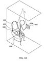
- FIG. 24 shows schematic views illustrating situations where the toilet apparatus equipped with the toilet seat apparatus 100 of this example is placed in a toilet.
- FIG. 24A shows the state of the toilet lid 300 opened to the point where the center of gravity G of the toilet lid 300 is located on the vertical line at its rotation axis C.
- the toilet apparatus of this example is of the so-called "service-water direct-pressure type", and hence is not provided with a low tank. Therefore the toilet apparatus can be placed next to the rear wall 950 of the toilet.
- the toilet lid 300 can be opened with a slight gap left between the toilet lid 300 and the rear wall 950.
- a protruding body 960 such as a window frame or decorative frame may be provided on the rear wall 950 of the toilet.
- the toilet lid 300 leans forward in the fully opened state, and thereby interference with the protruding body 960 can be prevented. That is, it is possible to eliminate annoyance due to the collision between the protruding body 960 and the toilet lid 300 occurring each time the toilet lid 300 is opened, and to also prevent the toilet lid 300 from being damaged.
- the amount of protrusion, or thickness, of the window frame or decorative frame provided on the rear wall 950 of the toilet is within 20 millimeters in most cases.
- the toilet seat apparatus 100 of this example can prevent interference with the protruding body 960 by setting the angle ⁇ shown in FIG. 23A to approximately 7 degrees. That is, when the center of gravity G of the lid 300 leans forward by approximately 7 degrees from the state of being located on the vertical line at its rotation axis C, collisions between the protruding body 960 and the toilet lid 300 can be prevented in most cases, achieving comfortable use.
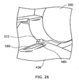
- FIGS. 25 and 26 are partial enlarged schematic views showing a stopper for restricting the opening angle of the toilet lid 300.
- the rotation shaft 728 of the toilet lid 300 protrudes laterally from the main body 400.
- the toilet lid 300 is provided with a pivotal support 370 opening like a slit. By inserting the rotation shaft 728 into this pivotal support 370, the toilet lid 300 is rotatably and pivotally supported on the main body.
- a stopper 480 is provided at the base end of the rotation shaft 728 of the main body 400.
- a light-receiving window 580 is provided behind the rotation shaft 728 of the main body 400. This is a window portion for receiving an infrared signal transmitted from a remote controller as described later in detail.
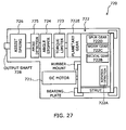
- FIG. 27 is a block diagram illustrating the toilet lid opening/closing unit that can be provided for electrically rotating the toilet lid 300.
- the toilet lid opening/closing unit 720 of this example can be incorporated in the main body 400, and its rotation shaft 728 can be rotated by a motor 721.
- Its driving mechanism includes a deceleration mechanism 722 for decelerating the rotation output of the motor 721, a torque limiter 723 for restricting the loaded maximum torque, an angle stopper 724 for restricting the rotation angle of the rotation shaft 728, an angle detector 725 for detecting the rotation angle of the rotation shaft 728, and an assist spring (elastic body) 726 for exerting a biasing force on the rotation shaft 728.
- the deceleration mechanism 722 includes a rotation detector 722A, a helical gear 722B, a worm gear 722C, a spur gear 722D, and a planetary gear 722E.
- the toilet lid 300 can be electrically opened/closed. Even in the state where this toilet lid opening/closing unit 720 is installed, the toilet lid 300 can be manually opened/closed. Whether electrically or manually, the assist spring 726 allows the toilet lid 300 to be lightly opened, and to reliably maintain the forward-leaning state when it is completely opened as described above with reference to FIG. 23 .
- FIG. 28 is a graph illustrating the relationship between the opening angle of the toilet lid 300 and the torque loaded on the rotation shaft 728 by the weight of the toilet lid 300.
- the assist spring 726 biases the rotation shaft 728 to the direction of opening the toilet lid 300.
- the assist spring 726 produces a torque gradually decreasing with respect to the opening angle of the toilet lid 300 as shown in FIG. 28 .
- the torque by the weight moment of the toilet lid 300 is alleviated. That is, the remainder of the torque of the assist spring 726 subtracted from the torque by the weight moment of the toilet lid 300 is the torque required for opening/closing the toilet lid 300.
- the toilet lid 300 can maintain standing.
- a torque in the opening direction is loaded on the rotation shaft 728.
- the toilet lid 300 when the toilet lid 300 is opened more than ⁇ 1, the toilet lid 300 is then automatically opened to the open-end angle.
- the maximum opening angle of the toilet lid 300 shown in FIG. 23A is set to an angle larger than this angle ⁇ 1. That is, in the state of the toilet lid 300 being stopped by the stopper 480 ( FIGS. 25 and 26 ), the torque by the biasing force of the assist spring 726 is larger than the torque by the weight moment of the toilet lid 300. Then, in the fully opened state, the toilet lid 300 is biased toward the stopper 480 by the assist spring 726, and can maintain the forward-leaning posture without falling forward.
- an assist spring 726 is incorporated in the electrically-driven toilet lid opening/closing unit 720.
- the invention is not limited thereto. More specifically, the assist spring 726 may be provided outside the toilet lid opening/closing unit 720. Alternatively, even if the toilet lid opening/closing unit 720 is not provided and the toilet lid is opened/closed only by manual operation, the forward-leaning posture as shown in FIG. 23A can be retained by providing a similar assist spring to bias the toilet lid 300 in the opening direction.
- the toilet lid opening/closing unit 720 shown in FIG. 27 can detect the position and operating state of the toilet lid 300 by using the rotation detector 722A provided in its deceleration mechanism 722 and the angle detector 725 for detecting the angle of the rotation shaft 728.
- the controller 640 FIG. 17 ) incorporated in the main body 400 can learn the open-end angle of the toilet lid 300. For example, if the toilet lid 300, upon being opened, reaches the open-end angle, the motor 721 stops rotation, which is detected by the rotation detector 722A of the deceleration mechanism 722. Furthermore, the opening angle of the toilet lid 300 can be learned by the angle detector 725. Hence, when the toilet lid 300 is opened the next time, the toilet lid 300 can be controlled so that the toilet lid 300 decreases its speed with approaching the opening angle and slowly reaches the open-end angle.
- the opening angle of the toilet lid 300 can be learned. From the next operation forward, the toilet lid 300 can be prevented from slamming on the protruding body 960.
- the toilet seat apparatus 100 newly learns the opening angle of the toilet lid 300, and can control the opening operation of the toilet lid 300 so as to avoid its slamming thereon from the next operation forward.
- FIG. 29 is a schematic view illustrating the operation of the toilet apparatus of this example in the case of simultaneously opening the toilet seat 200 and the toilet lid 300.
- the toilet lid 300 When the toilet seat 200 is manually opened from the state of the toilet seat 200 and the toilet lid 300 being closed as shown in FIG. 29A , the toilet lid 300 is pushed by the toilet seat 200 and simultaneously opened as shown in FIG. 29B . Then, as shown in FIG. 29C , when the toilet seat 200 is completely opened, the toilet lid 300 is in a state of leaning forward approximately 10 degrees relative to the fully opened state shown in FIG. 23 . However, even in this case, the biasing force of the assist spring 726 described above with reference to FIGS. 27 and 28 allows the toilet lid 300 to maintain the opened state without being closed.
- its angle detector 725 can be used to detect that the toilet lid 300 has been opened to the angle shown in FIG. 29C , and then the motor 721 can be controllably driven to automatically open the toilet lid 300 to the open-end angle.
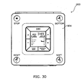
- FIGS. 30 and 31 are schematic views showing a remote controller that can control the toilet seat apparatus 100 of this example.
- the remote controller 900 of this example includes a main body 902 and a cover 904 reclosably hinged thereto.
- FIG. 30 shows the state of the cover 904 being closed
- FIG. 31 shows the state of the cover 904 being opened.
- the main body 902 and the cover 904 are each provided with switches. A user can manipulate these switches to control the operation of the toilet seat apparatus 100.
- the command signal to the main body 400 of the toilet seat apparatus 100 is transmitted from an infrared emitter 906 provided on both ends at the top of the remote controller.
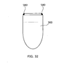
- FIGS. 32 and 33 are schematic views showing the position of the light-receiving window 580 provided on the main body 400. More specifically, FIG. 32 is a schematic view of the toilet lid 300 of the toilet seat apparatus 100 of this example in the closed state as viewed from above. FIG. 33 is a perspective view of the main body 400.
- the toilet seat apparatus 100 of this example has a structure where it is nearly entirely covered with the toilet lid 300 in the closed state of the toilet lid 300. As described above, this achieves a sleek appearance and facilitates cleaning. However, even in the closed state of the toilet lid 300, infrared radiation from the remote controller 900 needs to be received.
- a downward step is provided behind the pivotal support of the toilet lid 300, and a light-receiving window 580 is provided at the step.
- the light-receiving window 580 is scarcely seen from a user standing in front of the toilet bowl 800 even in the closed state of the toilet lid 300, doing no harm to the sleek appearance.
- infrared radiation transmitted from the remote controller can be reliably received.
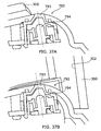
- FIG. 34 is a schematic view illustrating the path of infrared radiation transmitted from the remote controller 900.
- infrared radiation R is emitted upward from the infrared emitter 906 provided in the remote controller 900.
- the emitted infrared radiation is reflected by the ceiling of the toilet and directed to the main body 400.
- the opening angle of the toilet lid 300 is large, the infrared radiation reflected by the ceiling may be blocked by the toilet lid 300 and difficult to reach the light-receiving window 580 of the main body 400.
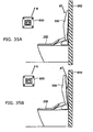
- FIG. 35 is a schematic view for illustrating the path of infrared radiation.
- the infrared radiation R reflected by the ceiling of the toilet is likely to be blocked by the toilet lid 300.
- the toilet apparatus is placed next to the rear wall 950 of the toilet, little gap remains between the toilet lid 300 and the rear wall 950 of the toilet when the opening angle of the toilet lid 300 is large.
- the infrared radiation R reflected by the ceiling cannot enter behind the toilet lid 300 and is difficult to reach the light-receiving window 580.
- the toilet lid 300 is spaced from the rear wall 950 and a sufficient gap occurs even in the case where the toilet apparatus is placed next to the rear wall 950. Consequently, the infrared radiation R reflected by the ceiling can enter behind the toilet lid 300 and reach the light-receiving window 580 directly or with suitably repeating reflection between the toilet lid 300 and the rear wall 950.
- the infrared signal transmitted from the remote controller 900 can be reliably received to ensure operation even in the opened state of the toilet lid 300.
- FIG. 36 is a schematic view showing the toilet seat apparatus 100 of this variation in the opened state of the toilet lid 300.
- the toilet seat apparatus 100 of this variation includes a lamp 792 at the upper rear of the main body 400.
- FIG. 37 is a schematic view showing a cross section of the lamp 792.
- the lamp 792 includes an LED (light emitting diode) 794 inside a window 793 embedded in the main body 400 generally coplanar with the surface of thereof. Light emitted from the LED 794 is extracted through the window 793 toward the ceiling of the toilet room. This light is extracted outside whether in the closed state of the toilet lid 300 as shown in FIG. 37A or in the opened state of the toilet lid 300 as shown in FIG. 37B , and can provide a user with soothing illumination.
- the lamp 792 can also serve to inform the user by blinking during preparation for operation, for example.
- the toilet lid 300 is maintained in the forward-leaning posture when it is fully opened, thereby achieving an effect of efficiently reflecting light from the lamp 792. More specifically, as shown in FIG. 37B , in the opened state of the toilet lid 300, the lamp 792 is located in front of the toilet lid 300 (see FIG. 23 ). That is, in the opened state of the toilet lid 300, light is emitted in front thereof from the lamp 792. According to this embodiment, part of this light can be reflected by the backside 302 of the toilet lid 300.
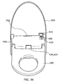
- FIG. 38 is a schematic view for illustrating the path of light emitted from the lamp 792.
- the toilet lid 300 leans forward in its opened state. Hence part of the light L emitted from the lamp 792 is reflected by the backside 302 of the toilet lid 300 and spreads forward. Likewise, the light is reflected also by the inner surface of the sidewall 303 (see FIG. 1 ) bent upright around the toilet lid 300. Thus the light L reflected by the backside 302 of the toilet seat and the inner surface of the sidewall 303 illuminates the remote controller 900 provided on the wall of the toilet. That is, as viewed from a user sitting on the toilet seat 200, the control panel of the remote controller 900 can be irradiated with soft light from behind. Toilet illumination may be often dazzling to a user who wakes up during sleep and uses the toilet at night.
- the light emitted from the lamp 792 provided in the main body 400 can be effectively reflected by the forward-leaning toilet lid 300 to illuminate the control panel of the remote controller 900 with moderate brightness, thereby enabling comfortable use.
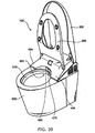
- FIG. 39 is a schematic view showing the toilet seat apparatus 100 of this example in the opened state of the toilet lid 300 and the toilet seat 200.
- the main body 400 has a configuration retracted to fit the opening edge of the bowl 810 of the toilet bowl 800. That is, the main body 400 is placed at the upper rear of the toilet bowl 800, and its front is formed into a curved concave surface 402 that is concavely curved along the shape of the opening edge of the bowl 810 of the toilet bowl 800 so as to slightly protrude from the opening edge of the bowl 810 toward the bowl 810. Extensions 404 extending forward along the opening edge of the bowl 810 are provided on the left and right of the curved concave surface 402.
- the curved concave surface 402 has a configuration that is elevated in its center vicinity and gradually lowered toward the extensions 404.
- the elevated portion in the center vicinity of the curved concave surface 402 is provided with an opening for advancing and retracting the water discharge nozzle and a nozzle damper 460 serving as a closing member for covering the opening.
- a warm air blowout port and a warm air damper 470 serving as a closing member for covering the warm air blowout port are provided. These are all reclosably supported, and all in the closed state during standby.
- the nozzle damper 460 is opened.
- warm air damper 470 is opened.
- the main body 400 retracts the main body 400, it is also possible to prevent the attachment of dirt to the backside of the main body 400 and to significantly improve cleanability. More specifically, according to this example, a user squatting down in front of the toilet bowl 800 can see close to the upper edge of the rear-end rim of the bowl 810. Thus the user, remaining in this posture, can clean the bowl 810 up to its rear end using a cloth or brush and reliably and easily confirm that any dirt has been cleaned off. Furthermore, in this embodiment, the amount of protrusion of the main body 400 to above the bowl 810 is held down. Hence it is also easy to clean dirt attached to the backside of the protrusion. For example, during cleaning with a cloth, the user can apply the cloth to the backside of the main body 400 and quickly wipe it from side to side.
- the sanitary cleansing apparatus 100 described above with reference to FIGS. 1 to 39 can achieve the same advantageous effects not only when it is installed on a toilet bowl of the service-water direct-pressure type, but also when it is installed on a toilet bowl equipped with a low tank.
- sanitary cleansing apparatus and the toilet apparatus are not limited to those described above with reference to FIGS. 1 to 22 , but any suitable modifications made by those skilled in the art for similarly practicing the invention and achieving similar effects are also encompassed within the scope of the invention as long as they include the features of the invention.
- This invention can provide a sanitary cleansing apparatus that can be substantially entirely covered with a toilet lid and that can also reliably perform human body detection, and a toilet apparatus provided therewith.
- this invention can provide a toilet seat apparatus capable of preventing collision with an object therebehind at the time of opening the toilet lid, and a toilet apparatus provided therewith.
Description
- This invention relates to a sanitary cleansing apparatus and a toilet apparatus, and more particularly to a sanitary cleansing apparatus provided with a reclosable toilet lid and a toilet.
- A sanitary cleansing apparatus retractably houses therein a water discharge nozzle for squirting wash water. The sanitary cleansing apparatus is placed on a sit-down toilet bowl so that the user's "bottom" can be cleansed with warm water. Typically, a toilet seat allowing a user to sit thereon and a toilet lid covering it are reclosably and pivotally supported on the sanitary cleansing apparatus (e.g., Patent Documents 1 and 2).
- On the other hand, many sanitary cleansing apparatuses include a human body detection sensor for detecting the access or presence of a user. On the basis of the detection result of the human body detection sensor, when a user enters or leaves the toilet, the toilet lid can be automatically opened/closed, the toilet bowl can be automatically flushed with wash water, and the temperature of the toilet seat and wash water can be controlled. Recently, an apparatus has been developed for automatically opening/closing the toilet seat and toilet lid by a motor (Patent Document 3).
Patent Document 1:JP 2003-265360A
Patent Document 2:JP 2004-267348A
Patent Document 3:JP 1-270831A (1989 -
JP 2003 235761 - If the toilet lid in its closed state covers not only the toilet seat but also the main body of the sanitary cleansing apparatus, a sleek appearance is achieved. Furthermore, the toilet lid eliminates gaps through which dust may intrude. Moreover, the toilet lid can improve cleanability in wipe and other cleaning.
- However, the toilet lid covering up to the main body of the sanitary cleansing apparatus causes a problem of shielding light in the detection range of an infrared transmission human body detection sensor. For this reason, as described in Patent Document 2, the human body detection sensor needs to be projected laterally from the sanitary cleansing apparatus, or to be exposed by providing a notch at the rear of the toilet lid. However, such configuration contrarily deteriorates the appearance and decreases the cleanability of the sanitary cleansing apparatus.
- On the other hand, whether the toilet lid is opened/closed manually or electrically, the open-end angle, or maximum opening angle, of the toilet lid is widely varied depending on the installation site. More specifically, in the case of a toilet of the low-tank type, a low tank is located behind the toilet lid. In the case of a toilet of the service-water direct-pressure type without a low tank, a shelf or bay window of the toilet may be located behind the toilet bowl.
- This invention provides a sanitary cleansing apparatus that can be substantially entirely covered with a toilet lid and that can also reliably perform human body detection, and a toilet apparatus provided therewith.
- Furthermore, this invention provides a toilet seat apparatus capable of preventing collision with an object therebehind at the time of opening the toilet lid, and a toilet apparatus provided therewith.
- According to an aspect of the invention, there is provided a sanitary cleansing apparatus as recited in claim 1.
-
-
FIG. 1 is a schematic perspective view of a toilet apparatus equipped with a sanitary cleansing apparatus according to the embodiment of the invention. -
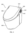
FIG. 2 is a schematic perspective view of a toilet apparatus equipped with a sanitary cleansing apparatus according to the embodiment of the invention. -
FIG. 3 is a perspective view of the sanitary cleansing apparatus of this example as viewed from the front. -
FIG. 4 is enlarged perspective view showing the installation portion of the humanbody detection sensor 500, whereFIG. 4 shows the closed state of thetoilet lid 300 -
FIG. 5 is enlarged perspective view showing the installation portion of the humanbody detection sensor 500, whereFIG. 5 shows the opened state of thetoilet lid 300. -
FIG. 6 is enlarged perspective view showing the installation portion of the humanbody detection sensor 500, whereFIG. 6 shows the opened state of thetoilet lid 300. -
FIG. 7 is an enlarged perspective view of the pivotal support of thetoilet lid 300 in its opened state as viewed from the front. -
FIG. 8 is a partially enlarged vertical cross-sectional views of themain body 400 with the humanbody detection sensor 500 embedded therein. -
FIG. 9 is a partially enlarged vertical cross-sectional view of themain body 400 with the humanbody detection sensor 500 embedded therein. -
FIG. 10 is a schematic view illustrating the range where a human body can be detected by the humanbody detection sensor 500 in thesanitary cleansing apparatus 100 of this example. -
FIG. 11 is a schematic view illustrating the range where a human body can be detected by the humanbody detection sensor 500 in thesanitary cleansing apparatus 100 of this example. -
FIG. 12 is a perspective view showing the installation portion of thetoilet lid 300 where thetransmissive window 310 is installed. -
FIG. 13 is a perspective view of thetransmissive window 310 as viewed from obliquely above. -
FIG. 14 is a perspective view of thetransmissive window 310 as viewed from obliquely below. -
FIG. 15 is a cross-sectional perspective view of thetransmissive window 310 cut horizontally. -
FIG. 16 is an enlarged cross-sectional view showing a cross section of the installation portion of thetransmissive window 310. -
FIG. 17 is a perspective view of the inside of themain body 400 as viewed from the front. -
FIG. 18 is a perspective view of the inside of themain body 400 as viewed from the rear. -
FIG. 19 is a perspective view for illustrating the installation structure of the toilet bowlwashing valve unit 730. -
FIG. 20 is a schematic view of the installation portion of the toilet bowlwashing valve unit 730 as viewed from above. -
FIG. 21 is a perspective view showing the positional relationship between the toilet lid opening/closing unit 720 and the toilet bowlwashing valve unit 730. -
FIG. 22 is a schematic view showing the toilet lid opening/closing unit 720 and the toilet bowlwashing valve unit 730 as viewed from behind -
FIG. 23 shows schematic views of the toilet seat apparatus as viewed laterally. -
FIG. 24 shows schematic views illustrating situations where the toilet apparatus equipped with thetoilet seat apparatus 100 of this example is placed in a toilet. -
FIG. 25 is a partial enlarged schematic view showing a stopper for restricting the opening angle of thetoilet lid 300. -
FIG. 26 is a partial enlarged schematic view showing a stopper for restricting the opening angle of thetoilet lid 300. -
FIG. 27 is a block diagram illustrating the toilet lid opening/closing unit that can be provided for electrically rotating thetoilet lid 300. -
FIG. 28 is a graph illustrating the relationship between the opening angle of thetoilet lid 300 and the torque loaded on therotation shaft 728 by the weight of thetoilet lid 300. -
FIG. 29 is a schematic view illustrating the operation of the toilet apparatus of this example in the case of simultaneously opening thetoilet seat 200 and thetoilet lid 300. -
FIG. 30 is a schematic view showing a remote controller that can control thetoilet seat apparatus 100 of this example. -
FIG. 31 is schematic view showing a remote controller that can control thetoilet seat apparatus 100 of this example. -
FIG. 32 is a schematic view showing the position of the light-receivingwindow 580 provided on themain body 400. -
FIG. 33 is a schematic view showing the position of the light-receivingwindow 580 provided on themain body 400. -
FIG. 34 is a schematic view illustrating the path of infrared radiation transmitted from theremote controller 900. -
FIG. 35 is a schematic view for illustrating the path of infrared radiation. -
FIG. 36 is a schematic view showing thetoilet seat apparatus 100 of this variation in the opened state of thetoilet lid 300. -
FIG. 37 is a schematic view showing a cross section of thelamp 792. -
FIG. 38 is a schematic view for illustrating the path of light emitted from thelamp 792. -
FIG. 39 is a schematic view showing thetoilet seat apparatus 100 of this example in the opened state of thetoilet lid 300 and thetoilet seat 200. -
- 100
- sanitary cleansing apparatus
- 200
- toilet seat
- 300
- toilet lid
- 302
- backside
- 303
- sidewall
- 305
- rear lower edge
- 310
- transmissive window
- 312
- rail groove
- 314
- hook
- 320
- window portion
- 330
- flange portion
- 340
- opening
- 350
- rail
- 360
- support bridge
- 365
- hooking recess
- 370
- pivotal support
- 372
- opening edge
- 380
- rotation axis
- 400
- main body
- 402
- curved concave surface
- 404
- extension
- 405
- step
- 408
- slope
- 410
- recessed portion
- 420
- seating sensor
- 430
- case cover
- 440
- exhaust port
- 450
- ejection hole
- 460
- nozzle damper
- 470
- warm air damper
- 480
- stopper
- 500
- human body detection sensor
- 510
- pyroelectric element
- 520
- lens
- 530
- substrate
- 580
- light-receiving window
- 610
- nozzle unit
- 620
- warm air unit
- 630
- deodorizing unit
- 640
- controller
- 650
- pump unit
- 660
- heat exchange unit
- 670
- display portion
- 680
- auxiliary control unit
- 690
- valve unit
- 700
- controller
- 710
- driver unit
- 720
- toilet lid opening/closing unit
- 721
- motor
- 722
- deceleration mechanism
- 724
- angle stopper
- 725
- angle detector
- 726
- assist spring
- 728
- rotation shaft
- 730
- toilet bowl washing valve unit
- 735
- feedwater piping
- 740
- room heating unit
- 760
- toilet bowl side baseplate
- 770
- installation board
- 772
- pin
- 775
- opening
- 780
- toilet seat opening/closing unit
- 792
- lamp
- 793
- window
- 800
- toilet bowl
- 810
- bowl
- 900
- remote controller
- 902
- main body
- 904
- cover
- 906
- infrared emitter
- 950
- rear wall
- 960
- protruding body
- An embodiment of the invention will now be described with reference to the drawings.
-
FIGS. 1 and2 are schematic perspective views of a toilet apparatus equipped with a sanitary cleansing apparatus according to the embodiment of the invention. -
FIG. 3 is a perspective view of the sanitary cleansing apparatus of this example as viewed from the front. - More specifically, a
sanitary cleansing apparatus 100 is placed on a sit-downtoilet bowl 800. Thesanitary cleansing apparatus 100 comprises amain body 400, and atoilet seat 200 and atoilet lid 300 reclosably and pivotally supported on themain body 400. From themain body 400, a water discharge nozzle (not shown) extends out into the bowl of thetoilet bowl 800 in response to user's switch manipulation and squirts water from a water discharge port provided near its tip so that the user's "bottom" can be cleansed. The term "water" used herein includes not only cold water but also heated warm water. Themain body 400 is suitably provided with various mechanisms such as a "deodorizing unit", "warm air unit", and "room heating unit". Anexhaust port 440 and anejection hole 450 are suitably provided on the side face of themain body 400. The internal configuration of themain body 400 is described later in detail. - The
toilet seat 200 is pivotally supported on themain body 400 relatively anteriorly, whereas thetoilet lid 300 is pivotally supported on themain body 400 relatively posteriorly. That is, the rotary shaft of thetoilet seat 200 is spaced longitudinally from the rotary shaft of thetoilet lid 300. As shown inFIGS. 1 and3 , in the opened state of thetoilet lid 300, themain body 400 and thetoilet seat 200 are exposed nearly completely, and a user can sit on thetoilet seat 200 without interfering with thetoilet lid 300. By pivotally supporting thetoilet lid 300 at the rear of themain body 400, thetoilet lid 300 can be distanced from the user sitting on thetoilet seat 200. Consequently, this allows a user sitting on thetoilet seat 200 to experience a feeling of openness and to enjoy comfortable use. Furthermore, even when the user sits on thetoilet seat 200 with a heavy jacket or tall dress rolled up, for example, the jacket or dress is less prone to contact with thetoilet lid 300, and the user is free from a feeling of oppression or sanitary discomfort. - On the other hand, as shown in
FIG. 2 , when thetoilet lid 300 is closed, thetoilet lid 300 nearly completely covers not only thetoilet seat 200 but also themain body 400. If the sanitary cleansing apparatus is nearly entirely covered with thetoilet lid 300 in this manner, a very smart, simple, and a sleek appearance is achieved. By entirely covering thesanitary cleansing apparatus 100 with thetoilet lid 300, no dirt or dust accumulates on themain body 400 as well as on thetoilet seat 200 while not in use. Furthermore, in the closed state of thetoilet lid 300, the upper face of thesanitary cleansing apparatus 100 has no "gaps" and "irregularities". Hence, in wipe cleaning with a damp cloth, the entire upper face of thetoilet lid 300 can be smoothly and quickly wiped, achieving good cleanability. - In this example, a step 405 (see also
FIG. 5 ) is formed on the side face of themain body 400. In the closed state of thetoilet lid 300, thestep 405 fits the rearlower edge 305 of thetoilet lid 300 in abutment or proximity, and the side face of themain body 400 and the side face of thetoilet lid 300 form a nearly continuous common surface. Consequently, in the closed state of thetoilet lid 300, a continuous plane extending from thetoilet lid 300 to themain body 400 is formed also on the side face of thesanitary cleansing apparatus 100. This further makes the appearance sleek and also prevents accumulation of dust and dirt. Furthermore, in the closed state of thetoilet lid 300, the side face of thesanitary cleansing apparatus 100 can be wipe cleaned smoothly and quickly without causing a damp cloth to get stuck. - The
main body 400 of the sanitary cleansing apparatus of this embodiment has an upper face between the pivotal support of thetoilet seat 200 and the pivotal support of thetoilet lid 300, the upper face being generally parallel to thetoilet lid 300 in the closed state. A humanbody detection sensor 500 is provided in the upper face. On the other hand, atransmissive window 310 is provided at the rear of thetoilet lid 300. -
FIGS. 4 to 6 are enlarged perspective views showing the installation portion of the humanbody detection sensor 500, whereFIG. 4 shows the closed state of thetoilet lid 300 andFIGS. 5 and6 show the opened state of thetoilet lid 300. -
FIG. 7 is an enlarged perspective view of the pivotal support of thetoilet lid 300 in its opened state as viewed from the front. - A recessed
portion 410 is formed in the upper face of themain body 400, and the humanbody detection sensor 500 is provided so that a portion thereof is embedded in the recessedportion 410. As described later in detail, the humanbody detection sensor 500 can be an infrared detection sensor. For example, a pyroelectric sensor can be used to detect the presence of a user with high accuracy. It is known that the pyroelectric sensor can detect movement of a heat-generating body within a prescribed detection range in front thereof. - As shown in
FIG. 4 , in the closed state of thetoilet lid 300, the humanbody detection sensor 500 detects the presence of a user located in front of the sanitary cleansing apparatus through thetransmissive window 310. That is, thetransmissive window 310 transmits infrared radiation to be detected by the humanbody detection sensor 500. When a pyroelectric sensor, for example, is used as the humanbody detection sensor 500, the pyroelectric sensor detects farinfrared radiation with a wavelength of approximately 10 micrometers. Hence thetransmissive window 310 is made of a material having a certain transmissivity for infrared radiation in this wavelength band. By using polyethylene, for example, as the material of thetransmissive window 310, the access or presence of a user can be detected through thetransmissive window 310 with high sensitivity even in the closed state of thetoilet lid 300. - On the other hand, the
toilet lid 300 supporting thetransmissive window 310 can be formed from a material having a lower transmissivity for infrared radiation than thetransmissive window 310. If thetoilet lid 300 is formed from a harder and more robust material than thetransmissive window 310, thetoilet lid 300 has a small deflection and deformation and is less susceptible to scratches. Furthermore, the color of thetoilet lid 300 can be freely chosen and easily adapted to the color of thetoilet bowl 800 and themain body 400. An example material of thetoilet lid 300 satisfying these requirements is polypropylene. - In the closed state of the
toilet lid 300, when the humanbody detection sensor 500 detects a user, thetoilet lid 300 can be automatically opened by, for example, activating a toilet lid opening/closing unit incorporated in themain body 400. Furthermore, it is possible to perform processes such as rapidly heating thetoilet seat 200, warming the toilet by activating a room heating unit provided in themain body 400, and preventing the attachment of dirt by previously flushing thetoilet bowl 800 with a small amount of wash water to wet the bowl. - As shown in
FIGS. 5 and6 , when thetoilet lid 300 is opened, no shielding body is located in front of the humanbody detection sensor 500. Hence the humanbody detection sensor 500 can directly detect the presence of a user. Furthermore, themain body 400 is provided with aseating sensor 420, enabling detection of the presence of a user sitting on thetoilet seat 200. Theseating sensor 420 can be an infrared sensor operable to emit infrared radiation and to detect the reflected light intensity, for example. -
FIG. 8 is a schematic view illustrating the structure of the humanbody detection sensor 500. More specifically,FIG. 8 shows the structure using a pyroelectric sensor as the humanbody detection sensor 500. - The pyroelectric sensor includes a
pyroelectric element 510 mounted on asubstrate 530 and alens 520 opposed to the light receiving surface of thepyroelectric element 510. Thepyroelectric element 510 is illustratively made of a pyroelectric material based on PZT (lead zirconate titanate), LiTaO3 (lithium tantalate), or PbTaO3 (lead tantalate), and partitioned into a plurality of detection regions. Thelens 520 is also partitioned into a plurality oflens portions 520L. When a heat-generating source such as a human body moves, the focusing pattern of infrared radiation by theselens bodies 520 also moves on the light receiving surface of thepyroelectric element 510, and hence its change can be detected. -
FIG. 9 is a partially enlarged vertical cross-sectional view of themain body 400 with the humanbody detection sensor 500 embedded therein. - In this example, as shown in
FIG. 9 , the humanbody detection sensor 500 is provided in proximity to the rear of thecase cover 430 on the upper face of themain body 400, that is, to the pivotal support of thetoilet lid 300, so as to slightly protrude from the upper face of themain body 400. Thus the distance between thetransmissive window 310 and the humanbody detection sensor 500 can be reduced. Consequently, a wide range can be detected while downsizing thetransmissive window 310. That is, a wide-angle range can be detected through thesmall transmissive window 310 as viewed from the humanbody detection sensor 500. - As described above, the
transmissive window 310 needs to be formed from a material having a higher transmissivity for infrared radiation than thetoilet lid 300. Thus thetransmissive window 310 may be different in color and texture from thetoilet lid 300, or may be susceptible to deformations and scratches due to low hardness. Even in such cases, according to this embodiment, thetransmissive window 310 can be downsized and provided near the rear edge of thetoilet lid 300. Hence thetransmissive window 310 is obscured, and the effect of preventing deformation and scratching is also achieved because it is less prone to being touched by hands. - Furthermore, as shown in
FIG. 9 , by providing a recessedportion 410 in themain body 400 and embedding part of the humanbody detection sensor 500 in the recessedportion 410, a wide angle can be detected without significantly projecting the humanbody detection sensor 500 from the upper face of thecase cover 430 of the main body. That is, human body detection can be reliably performed while maintaining cleanability of the upper face of thecase cover 430. -
FIGS. 10 and11 are schematic views illustrating the range where a human body can be detected by the humanbody detection sensor 500 in thesanitary cleansing apparatus 100 of this example. More specifically,FIGS. 10 and11 show horizontal and vertical detectable ranges, respectively. - As seen from
FIG. 10 , the humanbody detection sensor 500 can detect ahuman body 920 within a horizontal range of 40 degrees. On the other hand, as seen fromFIG. 11 , ahuman body 920 located in upper front of the sanitary cleansing apparatus can be detected within a vertical range of 33 degrees. These ranges are sufficient for detecting the presence of a user approaching thesanitary cleansing apparatus 100 or a user standing in front of thesanitary cleansing apparatus 100 in a standard-sized toilet. As shown inFIG. 11 , anadult 920 of ordinary stature can be detected when he/she comes to a distance of 2.5 meters from the rear edge of thetoilet bowl 800. Furthermore, the head of anadult 920 of ordinary stature can be also detected when he/she stands directly in front of thetoilet bowl 800. In general, even a child 910 a little less than one meter tall being able to use a toilet alone can be detected when he/she comes to approximately 100 millimeters from the front edge of thesanitary cleansing apparatus 100. Of course, the head of thechild 910 standing directly in front of thetoilet bowl 800 can be also detected. That is, the presence of users ranging from adults to children using the toilet bowl 800 (sanitary cleansing apparatus 100) can be reliably detected. - Next, the
transmissive window 310 and its installation structure used in this example are described in more detail. -
FIG. 12 is a perspective view showing the installation portion of thetoilet lid 300 where thetransmissive window 310 is installed. - At the rear edge of the
toilet lid 300, anopening 340 for installing thetransmissive window 310 is formed.Laminated rails 350 are provided on the front, left, and right sidewall of theopening 340. On the other hand, asupport bridge 360 is provided at the rear edge of theopening 340. Thetransmissive window 310 is slidably inserted from the rear side of thetoilet lid 300 and passed above thesupport bridge 360 along therails 350 in the direction of arrow A. -
FIG. 13 is a perspective view of thetransmissive window 310 as viewed from obliquely above. -
FIG. 14 is a perspective view of thetransmissive window 310 as viewed from obliquely below. -
FIG. 15 is a cross-sectional perspective view of thetransmissive window 310 cut horizontally. -
FIG. 16 is an enlarged cross-sectional view showing a cross section of the installation portion of thetransmissive window 310. - On the front, left, and right side face of the
transmissive window 310,rail grooves 312 to engage with therails 350 of thetoilet lid 300 are provided. As shown by arrow A inFIGS. 12 and13 , thetransmissive window 310 can be installed so as to occlude theopening 340 by being slid forward from the rear edge of thetoilet lid 300 while engaging therail grooves 312 with therails 350 on both lateral edges. When thetransmissive window 310 is slid to the front edge, therail groove 312 on its front edge engages with therail 350 on the front edge of theopening 340. Thus, in the state of thetransmissive window 310 being installed on thetoilet lid 300, the upper face of thetransmissive window 310 becomes continuous with the upper face of thetoilet lid 300 so that "steps" or "seams" therebetween almost vanish. A sleek appearance is achieved, allowing smooth wipe cleaning. - In the example shown in
FIGS. 12 to 16 ,rails 350 are provided on the sidewalls of theopening 340, andrail grooves 312 are provided on the side faces of thetransmissive window 310. However, the invention is not limited thereto. For example, conversely, it is also possible to use a structure where rail grooves are provided on the sidewalls of theopening 340 and rails are provided on the side faces of thetransmissive window 310. - On the other hand, at both ends on the backside of the rear of the
transmissive window 310, hooks (engaging protrusions) 314 are provided. In this example, thehook 314 is formed like a claw, and is capable of vertical elastic deformation because a portion of therail groove 312 is cut out. On the other hand, as shown inFIG. 12 , at both ends of thesupport bridge 360 of thetoilet lid 300, hooking recesses (engaging recesses) 365 are provided. When thetransmissive window 310 is slid to the front edge along therails 350, thehook 314 engages with the hookingrecess 365 and is fixed. Thus thetransmissive window 310 can be installed and fixed on thetoilet lid 300 reliably and easily. When thetransmissive window 310 installed on thetoilet lid 300 is pulled rearward with a force of a prescribed level or more, thehook 314 is elastically retracted and disengaged from the hookingrecess 365. Hence thetransmissive window 310 can be slid rearward along therails 350 and pulled out from thetoilet lid 300. Thus, when thetransmissive window 310 is broken or soiled, it can be easily removed from thetoilet lid 300 and replaced, serving convenience and also improving economy. - Furthermore, by providing
hooks 314 near the rear edge of thetransmissive window 310 in this manner, as shown inFIG. 6 , thehook 314 is scarcely seen from the user even in the opened state of thetoilet lid 300. Thus the appearance can be made sleek. - In the example shown in
FIGS. 12 to 16 , hooks (engaging protrusions) 314 are provided on thetransmissive window 310, and hooking recesses (engaging recesses) 365 are provided on thesupport bridge 360. However, the invention is not limited thereto. For example, conversely, it is also possible to use a structure where hooking recesses (engaging recesses) are provided on thetransmissive window 310 and hooks (engaging protrusions) are provided on thesupport bridge 360. - On the other hand, in this example, in the closed state of the
toilet lid 300, the humanbody detection sensor 500 detects the presence of a user through thetransmissive window 310. Hence, preferably, thetransmissive window 310 has a structure transmitting infrared radiation as much as possible. To this end, polyethylene, for example, is used as the material of thetransmissive window 310 as described above. Furthermore, as shown inFIGS. 15 and16 , in this structure, athin window portion 320 is provided to increase infrared transmissivity, and athick flange portion 330 is provided therearound for support and reinforcement. - For a
transmissive window 310 formed from high-density polyethylene, when thewindow portion 320 is thinned to a thickness of approximately 0.5 millimeters, a sufficient detection sensitivity is achieved even in the case of using a pyroelectric sensor as the humanbody detection sensor 500. On the other hand, if theflange portion 330 provided around thewindow portion 320 has a thickness of approximately 1.5 millimeters, thetransmissive window 310 can be prevented from disengagement and breakage under normal conditions of use. - As described above with reference to
FIG. 9 , in this example, the humanbody detection sensor 500 is protrusively provided below thetransmissive window 310. As shown inFIG. 9 , the spacing S between the upper end of thecase cover 430 and thetransmissive window 310 is approximately 1 millimeter. Hence, while thewindow portion 320 is deformed upon application of pressing force on thetransmissive window 310 in the closed state of thetoilet lid 300, the amount of deformation is restricted up to 1 millimeter, and further pressing force is sustained by thecase cover 430. Thus thetransmissive window 310 can be prevented from breakage and disengagement. - The
transmissive window 310 and its installation portion in this example have been described in detail. - Next, a more detailed description is given of the internal structure of the
main body 400 of a toilet apparatus in which thesanitary cleansing apparatus 100 of this example is combined with a toilet bowl of the service-water direct-pressure type. -
FIG. 17 is a perspective view of the inside of themain body 400 as viewed from the front. -
FIG. 18 is a perspective view of the inside of themain body 400 as viewed from the rear. - On the upper face of the
case cover 430, adisplay portion 670 is suitably provided near the humanbody detection sensor 500. Thedisplay portion 670 serves to suitably display the power on/off state of the toilet apparatus, for example. Furthermore, a toilet seat opening/closing unit 780 for automatically opening/closing thetoilet seat 200 is protrusively provided at the upper front of thecase cover 430. - On the other hand, a
nozzle unit 610, awarm air unit 620, and adeodorizing unit 630 are juxtaposed at the inner front of thecase cover 430. Thenozzle unit 610 includes a retractable water discharge nozzle, serving to cleanse the "bottom" of a user sitting on thetoilet seat 200 by squirting water thereto. Thewarm air unit 620 serves to dry the "bottom" of a user sitting on thetoilet seat 200 by applying warm air thereto. Thedeodorizing unit 630 serves to suck air in the bowl of thetoilet bowl 800, to deodorize it, and to eject it from theexhaust port 440. - An AC (alternating current)
controller 640 is provided at the inner front of thecase cover 430, and apump unit 650 and a heat exchange unit 660 are provided at the rear thereof. The water supplied to the heat exchange unit 660 is heated therein. Thepump unit 650 imparts pulsation to the water and supplies the pulsating water to thenozzle unit 610. - An
auxiliary control unit 680 is provided on the side face of thecase cover 430. Theauxiliary control unit 680 has a switch for operations such as cleansing the "bottom" by thenozzle unit 610, ensuring that the operation of thesanitary cleansing apparatus 100 is controllable even in the state that does not allow control by a remote controller (not shown). Furthermore, avalve unit 690 is provided at the lower rear of thecase cover 430. Thevalve unit 690 serves to control supply of water supplied from running water to thepump unit 650. - On the other hand, a DC (direct current)
controller 700 and adriver unit 710 are juxtaposed at the inner upper front of thecase cover 430. A toilet lid opening/closing unit 720 and a toilet bowlwashing valve unit 730 are juxtaposed at the inner rear of thecase cover 430. The toilet lid opening/closing unit 720 serves to open/close thetoilet lid 300. The toilet bowlwashing valve unit 730 serves to control supply of wash water used for flushing thetoilet bowl 800. That is, the toilet apparatus of this example has a structure of the so-called "service-water direct-pressure type", which performs washing by supplying the water supplied from running water to thetoilet bowl 800 through the toilet bowlwashing valve unit 730 without the intermediary of a low tank. - On the other hand, a
room heating unit 740 is provided at the inner rearmost of thecase cover 430. Theroom heating unit 740 serves to heat the toilet space equipped with the toilet apparatus by ejecting warm air from theejection hole 450. At the lower end is placed a power cord for externally supplying power such as AC 100 V. -
FIG. 19 is a perspective view for illustrating the installation structure of the toilet bowlwashing valve unit 730. -
FIG. 20 is a schematic view of the installation portion of the toilet bowlwashing valve unit 730 as viewed from above. - The toilet bowl
washing valve unit 730 is supported by a toiletbowl side baseplate 760 fixed behind thetoilet bowl 800, and is connected to thetoilet bowl 800 through afeedwater piping 735. Theinstallation board 770 of themain body 400 is fixed to the upper face of thetoilet bowl 800. The toilet bowlwashing valve unit 730 passes through anopening 775 provided in theinstallation board 770 and protrudes thereabove. -
FIG. 21 is a perspective view showing the positional relationship between the toilet lid opening/closing unit 720 and the toilet bowlwashing valve unit 730. -
FIG. 22 is a schematic view of these elements as viewed from behind. - The toilet lid opening/
closing unit 720 is screwed on a plurality ofpins 772 provided upright on theinstallation board 770. Thus the toilet lid opening/closing unit 720 is spaced from theinstallation board 770, and thefeedwater piping 735 is placed in that space. That is, the toilet lid opening/closing unit 720 is installed so as to straddle one pipe of the feedwater piping 735 of the toilet bowlwashing valve unit 730. The toilet lid opening/closing unit 720 and the toilet bowlwashing valve unit 730 are placed adjacent to each other at the rear of themain body 400. As described above with reference toFIGS. 17 and18 , the functional components of thetoilet apparatus 100 such as thenozzle unit 610 are suitably placed at the front of theinstallation board 770 and below the toilet lid opening/closing unit 720. - As described above, the toilet apparatus of this example includes a plurality of units having various functions. According to this example, as described above with reference to
FIGS. 17 and18 , thenozzle unit 610,warm air unit 620,deodorizing unit 630,pump unit 650, heat exchange unit 660, andvalve unit 690 are provided below themain body 400. The toilet bowlwashing valve unit 730 is internally installed at the rear of themain body 400, and the toilet lid opening/closing unit 720 is provided adjacent thereto at the rear of themain body 400. Thus, by providing the toilet lid opening/closing unit 720 at the rear of themain body 400, thetoilet lid 300 can be pivotally supported at the rear of themain body 400 so as to cover generally entirely the upper face of themain body 400 when thetoilet lid 300 is closed. Because the toilet lid opening/closing unit 720 is lifted above theinstallation board 770 by thepins 772 to accommodate therebelow the feedwater piping 735 connected to the toilet bowlwashing valve unit 730, the limited space can be effectively used. Here, instead of spacing the toilet lid opening/closing unit 720 from theinstallation board 770 by a plurality ofpins 772, the toilet bowlwashing valve unit 730 may be provided with a plurality of long legs and installed on theinstallation board 770. - The toilet bowl
washing valve unit 730 is internally installed at the rear of themain body 400, and the humanbody detection sensor 500 is provided thereabove. Thus the humanbody detection sensor 500 can be placed on the upper face of themain body 400 with the size of themain body 400 made compact, and as described above with reference toFIGS. 9 to 11 , a wide range can be reliably detected through asmall transmissive window 310. Here, the same advantageous effect can be achieved by providing the humanbody detection sensor 500 above the toilet lid opening/closing unit 720 rather than above the toilet bowlwashing valve unit 730. That is, by internally installing the toilet lid opening/closing unit 720 and the toilet bowlwashing valve unit 730 at the rear of themain body 400 and providing the humanbody detection sensor 500 above either thereof, human body detection can be reliably performed through thetransmissive window 310 with the size of themain body 400 made compact. - Next, the
toilet lid 300 of the toilet seat apparatus of this embodiment is described. -
FIG. 23 shows schematic views of the toilet seat apparatus as viewed laterally. - As shown in
FIG. 23A , in the completely opened state of thetoilet lid 300 of thetoilet seat apparatus 100 of this embodiment, the center of gravity G of thetoilet lid 300 is located on the closed side of the vertically upward direction above its rotation axis C. In other words, the center of gravity G of thetoilet lid 300 is located in front of the vertical line V at its rotation axis C. That is, in thetoilet seat apparatus 100 of this embodiment, thetoilet lid 300 remains standing with its back leaning forward when it is fully opened. Then, even if a window frame of the toilet, for example, is located behind thetoilet lid 300, collision can be prevented. - It is noted that the
toilet seat apparatus 100 ofthis example described below is similarly applicable to the toilet apparatus of the so-called "low-tank type". - As shown in
FIG. 23A , in the completely opened state of thetoilet lid 300, thetoilet lid 300 is located on the closed side of the vertically upward direction above its rotation axis C. That is, in thetoilet seat apparatus 100 of this embodiment, thetoilet lid 300 remains standing with its back leaning forward when it is fully opened. -
FIG. 24 shows schematic views illustrating situations where the toilet apparatus equipped with thetoilet seat apparatus 100 of this example is placed in a toilet. -
FIG. 24A shows the state of thetoilet lid 300 opened to the point where the center of gravity G of thetoilet lid 300 is located on the vertical line at its rotation axis C. The toilet apparatus of this example is of the so-called "service-water direct-pressure type", and hence is not provided with a low tank. Therefore the toilet apparatus can be placed next to therear wall 950 of the toilet. Here, if therear wall 950 of the toilet is flat, thetoilet lid 300 can be opened with a slight gap left between thetoilet lid 300 and therear wall 950. - However, a protruding
body 960 such as a window frame or decorative frame may be provided on therear wall 950 of the toilet. In this case, according to this embodiment, thetoilet lid 300 leans forward in the fully opened state, and thereby interference with the protrudingbody 960 can be prevented. That is, it is possible to eliminate annoyance due to the collision between the protrudingbody 960 and thetoilet lid 300 occurring each time thetoilet lid 300 is opened, and to also prevent thetoilet lid 300 from being damaged. - The amount of protrusion, or thickness, of the window frame or decorative frame provided on the
rear wall 950 of the toilet is within 20 millimeters in most cases. Hence thetoilet seat apparatus 100 of this example can prevent interference with the protrudingbody 960 by setting the angle θ shown inFIG. 23A to approximately 7 degrees. That is, when the center of gravity G of thelid 300 leans forward by approximately 7 degrees from the state of being located on the vertical line at its rotation axis C, collisions between the protrudingbody 960 and thetoilet lid 300 can be prevented in most cases, achieving comfortable use. -
FIGS. 25 and26 are partial enlarged schematic views showing a stopper for restricting the opening angle of thetoilet lid 300. - The
rotation shaft 728 of thetoilet lid 300 protrudes laterally from themain body 400. Thetoilet lid 300 is provided with apivotal support 370 opening like a slit. By inserting therotation shaft 728 into thispivotal support 370, thetoilet lid 300 is rotatably and pivotally supported on the main body. On the other hand, astopper 480 is provided at the base end of therotation shaft 728 of themain body 400. When thetoilet lid 300 is opened, as shown inFIG. 26 , the openingedge 372 of thetoilet lid 300 abuts thestopper 480, and the open-end angle is restricted. Thus, as shown inFIG. 23 , the open-end angle of thetoilet lid 300 can be reliably restricted. - As shown in
FIGS. 25 and26 , a light-receivingwindow 580 is provided behind therotation shaft 728 of themain body 400. This is a window portion for receiving an infrared signal transmitted from a remote controller as described later in detail. -
FIG. 27 is a block diagram illustrating the toilet lid opening/closing unit that can be provided for electrically rotating thetoilet lid 300. - The toilet lid opening/
closing unit 720 of this example can be incorporated in themain body 400, and itsrotation shaft 728 can be rotated by amotor 721. Its driving mechanism includes adeceleration mechanism 722 for decelerating the rotation output of themotor 721, atorque limiter 723 for restricting the loaded maximum torque, anangle stopper 724 for restricting the rotation angle of therotation shaft 728, anangle detector 725 for detecting the rotation angle of therotation shaft 728, and an assist spring (elastic body) 726 for exerting a biasing force on therotation shaft 728. Thedeceleration mechanism 722 includes arotation detector 722A, ahelical gear 722B, a worm gear 722C, aspur gear 722D, and aplanetary gear 722E. - By using this toilet lid opening/
closing unit 720, thetoilet lid 300 can be electrically opened/closed. Even in the state where this toilet lid opening/closing unit 720 is installed, thetoilet lid 300 can be manually opened/closed. Whether electrically or manually, theassist spring 726 allows thetoilet lid 300 to be lightly opened, and to reliably maintain the forward-leaning state when it is completely opened as described above with reference toFIG. 23 . -
FIG. 28 is a graph illustrating the relationship between the opening angle of thetoilet lid 300 and the torque loaded on therotation shaft 728 by the weight of thetoilet lid 300. - As shown in
FIG. 23B , in the case of thetoilet seat apparatus 100 of this example, in the closed state of thetoilet lid 300, its center of gravity G is located vertically below the horizontal line H at the rotation axis C. Hence, in the course of opening thetoilet lid 300 from this state, when the center of gravity G comes on the horizontal line H, the torque at therotation shaft 728 by the weight moment of thetoilet lid 300 takes on the maximum Tmax. When thetoilet lid 300 is further opened, the torque by the weight moment gradually decreases. If theassist spring 726 is not provided, the torque vanishes when the center of gravity G comes vertically above the rotation shaft 728 (θ0), or on the vertical line V (FIG. 23 ). That is, at this angle θ0, thetoilet lid 300 can maintain standing. In this embodiment, the open-end angle of thetoilet lid 300 is smaller than this standing angle θ0. That is, as described above with reference toFIGS. 25 and26 , the open-end angle is restricted to less than θ0 by thestopper 480. - In this embodiment, the
assist spring 726 biases therotation shaft 728 to the direction of opening thetoilet lid 300. Theassist spring 726 produces a torque gradually decreasing with respect to the opening angle of thetoilet lid 300 as shown inFIG. 28 . By providing such anassist spring 726, the torque by the weight moment of thetoilet lid 300 is alleviated. That is, the remainder of the torque of theassist spring 726 subtracted from the torque by the weight moment of thetoilet lid 300 is the torque required for opening/closing thetoilet lid 300. Hence, at angle θ1 where these are balanced, thetoilet lid 300 can maintain standing. When thetoilet lid 300 is opened more than θ1, a torque in the opening direction is loaded on therotation shaft 728. That is, when thetoilet lid 300 is opened more than θ1, thetoilet lid 300 is then automatically opened to the open-end angle. In this embodiment, the maximum opening angle of thetoilet lid 300 shown inFIG. 23A is set to an angle larger than this angle θ1. That is, in the state of thetoilet lid 300 being stopped by the stopper 480 (FIGS. 25 and26 ), the torque by the biasing force of theassist spring 726 is larger than the torque by the weight moment of thetoilet lid 300. Then, in the fully opened state, thetoilet lid 300 is biased toward thestopper 480 by theassist spring 726, and can maintain the forward-leaning posture without falling forward. - In the example shown in
FIG. 27 , anassist spring 726 is incorporated in the electrically-driven toilet lid opening/closing unit 720. However, the invention is not limited thereto. More specifically, theassist spring 726 may be provided outside the toilet lid opening/closing unit 720. Alternatively, even if the toilet lid opening/closing unit 720 is not provided and the toilet lid is opened/closed only by manual operation, the forward-leaning posture as shown inFIG. 23A can be retained by providing a similar assist spring to bias thetoilet lid 300 in the opening direction. - The toilet lid opening/
closing unit 720 shown inFIG. 27 can detect the position and operating state of thetoilet lid 300 by using therotation detector 722A provided in itsdeceleration mechanism 722 and theangle detector 725 for detecting the angle of therotation shaft 728. On the basis of detection information thereof, the controller 640 (FIG. 17 ) incorporated in themain body 400 can learn the open-end angle of thetoilet lid 300. For example, if thetoilet lid 300, upon being opened, reaches the open-end angle, themotor 721 stops rotation, which is detected by therotation detector 722A of thedeceleration mechanism 722. Furthermore, the opening angle of thetoilet lid 300 can be learned by theangle detector 725. Hence, when thetoilet lid 300 is opened the next time, thetoilet lid 300 can be controlled so that thetoilet lid 300 decreases its speed with approaching the opening angle and slowly reaches the open-end angle. - Then, for example, when the toilet apparatus of this example is placed in a toilet having a protruding
body 960 with a large amount of protrusion described above with reference toFIG. 24B and is operated for the first time, the opening angle of thetoilet lid 300 can be learned. From the next operation forward, thetoilet lid 300 can be prevented from slamming on the protrudingbody 960. Likewise, also in the case of additionally placing a decorative frame having a large amount of protrusion on the rear wall of the toilet after placing the toilet apparatus of this example and starting its use, thetoilet seat apparatus 100 newly learns the opening angle of thetoilet lid 300, and can control the opening operation of thetoilet lid 300 so as to avoid its slamming thereon from the next operation forward. -
FIG. 29 is a schematic view illustrating the operation of the toilet apparatus of this example in the case of simultaneously opening thetoilet seat 200 and thetoilet lid 300. - When the
toilet seat 200 is manually opened from the state of thetoilet seat 200 and thetoilet lid 300 being closed as shown inFIG. 29A , thetoilet lid 300 is pushed by thetoilet seat 200 and simultaneously opened as shown inFIG. 29B . Then, as shown inFIG. 29C , when thetoilet seat 200 is completely opened, thetoilet lid 300 is in a state of leaning forward approximately 10 degrees relative to the fully opened state shown inFIG. 23 . However, even in this case, the biasing force of theassist spring 726 described above with reference toFIGS. 27 and28 allows thetoilet lid 300 to maintain the opened state without being closed. - In addition, in the case of providing the toilet lid opening/
closing unit 720 described above with reference toFIG. 27 , itsangle detector 725 can be used to detect that thetoilet lid 300 has been opened to the angle shown inFIG. 29C , and then themotor 721 can be controllably driven to automatically open thetoilet lid 300 to the open-end angle. - Next, a description is given of other effects achieved by restricting the open-end angle of the
toilet lid 300 in this embodiment. - By maintaining the
toilet lid 300 in the forward-leaning posture, advantageously, infrared radiation transmitted from a remote controller can be reliably received. -
FIGS. 30 and31 are schematic views showing a remote controller that can control thetoilet seat apparatus 100 of this example. - The
remote controller 900 of this example includes amain body 902 and acover 904 reclosably hinged thereto.FIG. 30 shows the state of thecover 904 being closed, andFIG. 31 shows the state of thecover 904 being opened. - The
main body 902 and thecover 904 are each provided with switches. A user can manipulate these switches to control the operation of thetoilet seat apparatus 100. The command signal to themain body 400 of thetoilet seat apparatus 100 is transmitted from aninfrared emitter 906 provided on both ends at the top of the remote controller. -
FIGS. 32 and33 are schematic views showing the position of the light-receivingwindow 580 provided on themain body 400. More specifically,FIG. 32 is a schematic view of thetoilet lid 300 of thetoilet seat apparatus 100 of this example in the closed state as viewed from above.FIG. 33 is a perspective view of themain body 400. - As described above with reference to
FIGS. 1 and2 , thetoilet seat apparatus 100 of this example has a structure where it is nearly entirely covered with thetoilet lid 300 in the closed state of thetoilet lid 300. As described above, this achieves a sleek appearance and facilitates cleaning. However, even in the closed state of thetoilet lid 300, infrared radiation from theremote controller 900 needs to be received. Hence, as shown inFIGS. 25 ,26 ,32 , and33 , in this example, a downward step is provided behind the pivotal support of thetoilet lid 300, and a light-receivingwindow 580 is provided at the step. In the case of providing a light-receivingwindow 580 at this position, the light-receivingwindow 580 is scarcely seen from a user standing in front of thetoilet bowl 800 even in the closed state of thetoilet lid 300, doing no harm to the sleek appearance. - According to this embodiment, by maintaining the
toilet lid 300 in the forward-leaning posture at the open-end angle, infrared radiation transmitted from the remote controller can be reliably received. -
FIG. 34 is a schematic view illustrating the path of infrared radiation transmitted from theremote controller 900. - As shown by arrow R, infrared radiation R is emitted upward from the
infrared emitter 906 provided in theremote controller 900. The emitted infrared radiation is reflected by the ceiling of the toilet and directed to themain body 400. However, if the opening angle of thetoilet lid 300 is large, the infrared radiation reflected by the ceiling may be blocked by thetoilet lid 300 and difficult to reach the light-receivingwindow 580 of themain body 400. -
FIG. 35 is a schematic view for illustrating the path of infrared radiation. - As shown in
FIG. 35A , if the opening angle of thetoilet lid 300 is large, the infrared radiation R reflected by the ceiling of the toilet is likely to be blocked by thetoilet lid 300. In particular, in the case where the toilet apparatus is placed next to therear wall 950 of the toilet, little gap remains between thetoilet lid 300 and therear wall 950 of the toilet when the opening angle of thetoilet lid 300 is large. Hence the infrared radiation R reflected by the ceiling cannot enter behind thetoilet lid 300 and is difficult to reach the light-receivingwindow 580. - In contrast, as shown in
FIG. 35B , if the opening angle of thetoilet lid 300 is restricted to force the forward-leaning posture, thetoilet lid 300 is spaced from therear wall 950 and a sufficient gap occurs even in the case where the toilet apparatus is placed next to therear wall 950. Consequently, the infrared radiation R reflected by the ceiling can enter behind thetoilet lid 300 and reach the light-receivingwindow 580 directly or with suitably repeating reflection between thetoilet lid 300 and therear wall 950. - As described above, according to this embodiment, while the
toilet lid 300 nearly entirely covers thetoilet seat apparatus 100, the infrared signal transmitted from theremote controller 900 can be reliably received to ensure operation even in the opened state of thetoilet lid 300. - Next, a description is given of a variation where the
toilet seat apparatus 100 is provided with a lamp. -
FIG. 36 is a schematic view showing thetoilet seat apparatus 100 of this variation in the opened state of thetoilet lid 300. - The
toilet seat apparatus 100 of this variation includes alamp 792 at the upper rear of themain body 400. -
FIG. 37 is a schematic view showing a cross section of thelamp 792. As shown in this figure, thelamp 792 includes an LED (light emitting diode) 794 inside awindow 793 embedded in themain body 400 generally coplanar with the surface of thereof. Light emitted from theLED 794 is extracted through thewindow 793 toward the ceiling of the toilet room. This light is extracted outside whether in the closed state of thetoilet lid 300 as shown inFIG. 37A or in the opened state of thetoilet lid 300 as shown inFIG. 37B , and can provide a user with soothing illumination. Thelamp 792 can also serve to inform the user by blinking during preparation for operation, for example. - According to this embodiment, the
toilet lid 300 is maintained in the forward-leaning posture when it is fully opened, thereby achieving an effect of efficiently reflecting light from thelamp 792. More specifically, as shown inFIG. 37B , in the opened state of thetoilet lid 300, thelamp 792 is located in front of the toilet lid 300 (seeFIG. 23 ). That is, in the opened state of thetoilet lid 300, light is emitted in front thereof from thelamp 792. According to this embodiment, part of this light can be reflected by thebackside 302 of thetoilet lid 300. -
FIG. 38 is a schematic view for illustrating the path of light emitted from thelamp 792. - In this embodiment, the
toilet lid 300 leans forward in its opened state. Hence part of the light L emitted from thelamp 792 is reflected by thebackside 302 of thetoilet lid 300 and spreads forward. Likewise, the light is reflected also by the inner surface of the sidewall 303 (seeFIG. 1 ) bent upright around thetoilet lid 300. Thus the light L reflected by thebackside 302 of the toilet seat and the inner surface of thesidewall 303 illuminates theremote controller 900 provided on the wall of the toilet. That is, as viewed from a user sitting on thetoilet seat 200, the control panel of theremote controller 900 can be irradiated with soft light from behind. Toilet illumination may be often dazzling to a user who wakes up during sleep and uses the toilet at night. According to this example, even in such a case, the light emitted from thelamp 792 provided in themain body 400 can be effectively reflected by the forward-leaningtoilet lid 300 to illuminate the control panel of theremote controller 900 with moderate brightness, thereby enabling comfortable use. - Next, the structure of the
toilet seat apparatus 100 of this example is described in more detail. -
FIG. 39 is a schematic view showing thetoilet seat apparatus 100 of this example in the opened state of thetoilet lid 300 and thetoilet seat 200. - In this example, the
main body 400 has a configuration retracted to fit the opening edge of thebowl 810 of thetoilet bowl 800. That is, themain body 400 is placed at the upper rear of thetoilet bowl 800, and its front is formed into a curvedconcave surface 402 that is concavely curved along the shape of the opening edge of thebowl 810 of thetoilet bowl 800 so as to slightly protrude from the opening edge of thebowl 810 toward thebowl 810.Extensions 404 extending forward along the opening edge of thebowl 810 are provided on the left and right of the curvedconcave surface 402. The curvedconcave surface 402 has a configuration that is elevated in its center vicinity and gradually lowered toward theextensions 404. - The elevated portion in the center vicinity of the curved
concave surface 402 is provided with an opening for advancing and retracting the water discharge nozzle and anozzle damper 460 serving as a closing member for covering the opening. On its right side, a warm air blowout port and awarm air damper 470 serving as a closing member for covering the warm air blowout port are provided. These are all reclosably supported, and all in the closed state during standby. When the water discharge nozzle advances for cleansing the "bottom" of a user sitting on thetoilet seat 200, thenozzle damper 460 is opened. When warm air is blown from thewarm air unit 620 toward the "bottom" of a user, thewarm air damper 470 is opened. - By retracting the front of the
main body 400 to form a curvedconcave surface 402, urine is unlikely to splash thereon even during male standing urination, and no visual narrowness is inflicted on the user. By elevating the center vicinity of the curvedconcave surface 402, the elevated portion in the center vicinity of the curvedconcave surface 402 can receive urine and drop it into thebowl 810 even if urine splashes on themain body 400 during male standing urination. That is, it is possible to prevent urine from splashing on the slope 408 of themain body 400 and to minimize dirt due to urine. - Furthermore, by thus retracting the
main body 400, it is also possible to prevent the attachment of dirt to the backside of themain body 400 and to significantly improve cleanability. More specifically, according to this example, a user squatting down in front of thetoilet bowl 800 can see close to the upper edge of the rear-end rim of thebowl 810. Thus the user, remaining in this posture, can clean thebowl 810 up to its rear end using a cloth or brush and reliably and easily confirm that any dirt has been cleaned off. Furthermore, in this embodiment, the amount of protrusion of themain body 400 to above thebowl 810 is held down. Hence it is also easy to clean dirt attached to the backside of the protrusion. For example, during cleaning with a cloth, the user can apply the cloth to the backside of themain body 400 and quickly wipe it from side to side. - The embodiment of the invention has been described with reference to examples. However, the invention is not limited to these examples. For example, the
sanitary cleansing apparatus 100 described above with reference toFIGS. 1 to 39 can achieve the same advantageous effects not only when it is installed on a toilet bowl of the service-water direct-pressure type, but also when it is installed on a toilet bowl equipped with a low tank. - The examples described above with reference to
FIGS. 1 to 39 can be combined with each other as long as technically feasible, and such combinations are also encompassed within the scope of the invention. - The structure and operation of the sanitary cleansing apparatus and the toilet apparatus are not limited to those described above with reference to
FIGS. 1 to 22 , but any suitable modifications made by those skilled in the art for similarly practicing the invention and achieving similar effects are also encompassed within the scope of the invention as long as they include the features of the invention. - This invention can provide a sanitary cleansing apparatus that can be substantially entirely covered with a toilet lid and that can also reliably perform human body detection, and a toilet apparatus provided therewith.
- Furthermore, this invention can provide a toilet seat apparatus capable of preventing collision with an object therebehind at the time of opening the toilet lid, and a toilet apparatus provided therewith.
Claims (4)
- A sanitary cleansing apparatus (100) comprising:a main body (400) incorporating a water discharge nozzle that squirts water from a water discharge port;a toilet seat (200) rotatably and pivotally supported at a relatively anterior position of the main body (400); anda toilet lid (300) rotatably and pivotally supported at a relatively posterior position of the main body (400) and generally entirely covering an upper face of the toilet seat (200) and the main body (400) in a closed state characterised in that the apparatus further comprises:a transmissive window (310) provided at a rear of the toilet lid (300) and formed from a material different from that of the toilet lid (300), the transmissive window (310) including a window portion thinner than the toilet lid (300); anda human body detection sensor (500) provided in the upper face of the main body and being capable of detecting a human body through the transmissive window in the closed state of the toilet lid, whereinthe human body detection sensor (500) includes a lens (520) for focusing infrared radiation emitted from the human body and a pyroelectric element (510) for detecting the infrared radiation,a recessed portion (410) that is recessed relative to its surroundings is provided in the upper face of the main body (400),at least a portion of the lens is embedded in the recessed portion (410), and another portion protrudes from the main body (400), andthe lens of the human body detection sensor (500) is placed below the window (310) portion of the transmissive window in the closed state of the toilet lid (300).
- The sanitary cleansing apparatus according to claim 1, wherein the transmissive window (310) is removably installed on the toilet lid (300).
- The sanitary cleansing apparatus according to claim 2, wherein
the toilet lid (300) includes an opening (340) provided at its rear edge,
a rail (350) is provided on one of a side face of the transmissive window (310) and a sidewall of the opening,
a rail groove (312) is provided on the other of the side face of the transmissive window (310) and the sidewall of the opening (340), and
the transmissive window (310) can be installed on the toilet lid (300) by being slid with the rail (350) engaged with the rail groove (312). - The sanitary cleansing apparatus according to claim 3, wherein
an engaging protrusion (314) is provided on one of the transmissive window (310) and the opening (340),
an engaging recess (365) is provided on the other of the transmissive window (310) and the opening (340), and
the engaging protrusion (314) is engaged with the engaging recess (365) when the transmissive window (310) is installed on the toilet lid (300).
Applications Claiming Priority (4)
| Application Number | Priority Date | Filing Date | Title |
|---|---|---|---|
| JP2006034731 | 2006-02-13 | ||
| JP2006034730A JP3931920B1 (en) | 2006-02-13 | 2006-02-13 | Sanitary washing device and toilet device |
| JP2006152868A JP4999049B2 (en) | 2006-05-31 | 2006-05-31 | Toilet seat device and toilet device |
| PCT/JP2007/052522 WO2007094323A1 (en) | 2006-02-13 | 2007-02-13 | Sanitary flushing device and toilet device |
Publications (4)
| Publication Number | Publication Date |
|---|---|
| EP2005872A2 EP2005872A2 (en) | 2008-12-24 |
| EP2005872A9 EP2005872A9 (en) | 2009-07-08 |
| EP2005872A4 EP2005872A4 (en) | 2011-03-23 |
| EP2005872B1 true EP2005872B1 (en) | 2015-10-21 |
Family
ID=38371503
Family Applications (1)
| Application Number | Title | Priority Date | Filing Date |
|---|---|---|---|
| EP07714104.2A Active EP2005872B1 (en) | 2006-02-13 | 2007-02-13 | Sanitary cleansing apparatus |
Country Status (5)
| Country | Link |
|---|---|
| US (1) | US8082607B2 (en) |
| EP (1) | EP2005872B1 (en) |
| KR (1) | KR20080111455A (en) |
| TW (1) | TW200745421A (en) |
| WO (1) | WO2007094323A1 (en) |
Families Citing this family (28)
| Publication number | Priority date | Publication date | Assignee | Title |
|---|---|---|---|---|
| JP4105209B2 (en) * | 2005-07-26 | 2008-06-25 | 三菱電機株式会社 | Hand dryer |
| JP5633267B2 (en) * | 2009-09-30 | 2014-12-03 | Toto株式会社 | Sanitary washing device |
| JP5660106B2 (en) * | 2012-11-09 | 2015-01-28 | Toto株式会社 | Toilet equipment |
| US9212477B2 (en) | 2013-09-05 | 2015-12-15 | Ilan Tiagai | Electronic automatically adjusting bidet with visual object recognition software |
| US10465366B2 (en) | 2014-05-27 | 2019-11-05 | As America, Inc. | Sanitaryware cleaning system |
| CA2950409C (en) | 2014-05-27 | 2023-04-04 | As Ip Holdco, Llc | Sanitaryware cleaning system |
| DE102015106220A1 (en) * | 2015-04-22 | 2016-10-27 | Duravit Aktiengesellschaft | sanitary facilities |
| JP6617910B2 (en) * | 2015-07-30 | 2019-12-11 | Toto株式会社 | Sanitary washing device and toilet device |
| WO2017165349A1 (en) * | 2016-03-22 | 2017-09-28 | Spectrum Brands, Inc. | Garage door opener with touch sensor authentication |
| TW201739990A (en) * | 2016-03-29 | 2017-11-16 | 驪住股份有限公司 | Toilet device |
| JP6249309B1 (en) * | 2016-08-17 | 2017-12-20 | Toto株式会社 | Toilet equipment |
| JP6183516B1 (en) | 2016-08-17 | 2017-08-23 | Toto株式会社 | Toilet equipment |
| JP6249061B1 (en) * | 2016-08-17 | 2017-12-20 | Toto株式会社 | Toilet equipment |
| JP6800424B2 (en) * | 2016-08-23 | 2020-12-16 | Toto株式会社 | Toilet device |
| JP2018031140A (en) * | 2016-08-23 | 2018-03-01 | Toto株式会社 | Toilet device |
| JP6800425B2 (en) * | 2016-08-23 | 2020-12-16 | Toto株式会社 | Sanitary cleaning equipment |
| CN106108760B (en) * | 2016-08-25 | 2018-11-06 | 京东方科技集团股份有限公司 | A kind of intelligent closestool |
| WO2018140634A1 (en) | 2017-01-25 | 2018-08-02 | As Ip Holdco, Llc | Sanitaryware cleaning system |
| JP6443771B2 (en) * | 2017-02-01 | 2018-12-26 | Toto株式会社 | Toilet equipment |
| JP6447889B2 (en) | 2017-02-02 | 2019-01-09 | Toto株式会社 | Sanitary washing device and method of assembling the same |
| JP2018122029A (en) * | 2017-02-03 | 2018-08-09 | Toto株式会社 | Toilet device |
| CN107174159A (en) * | 2017-05-27 | 2017-09-19 | 厦门致杰智能科技有限公司 | A kind of infrared light intellectual water closet automaton and autocontrol method |
| CN108685518B (en) * | 2018-05-29 | 2020-07-07 | 宁波市晶杰国际物流有限公司 | Intelligent toilet seat cover pad paper replacing device |
| CN109056947A (en) * | 2018-11-02 | 2018-12-21 | 济宁衍利博机械有限公司 | The intelligent closestool in not plug-in source |
| CN110151041B (en) * | 2019-04-03 | 2024-02-06 | 台州艺马卫浴有限公司 | Intelligent toilet lid |
| CN110269536A (en) * | 2019-04-24 | 2019-09-24 | 天津幻丝眼镜有限公司 | A kind of automatic toilet mentions lid device |
| JP6979177B2 (en) * | 2019-07-05 | 2021-12-08 | Toto株式会社 | Sanitary cleaning equipment |
| KR102497869B1 (en) * | 2022-02-17 | 2023-02-09 | 주식회사 엔씨엠 | Automatic sterilization and cleaning device and automatic sterilization and cleaning method inside the toilet bowl of the bidet |
Family Cites Families (35)
| Publication number | Priority date | Publication date | Assignee | Title |
|---|---|---|---|---|
| JPS6114334A (en) * | 1984-06-29 | 1986-01-22 | 松下電器産業株式会社 | Sanitary cleaning apparatus |
| JP2651698B2 (en) | 1988-04-25 | 1997-09-10 | 加藤電機株式会社 | Automatic opening / closing device for toilet seat, toilet lid, etc., bearing device used for the device, and Western toilet device |
| CN2060915U (en) | 1989-07-06 | 1990-08-22 | 长春康力公司 | Detective devices using infrared ray |
| JPH0424219A (en) | 1990-05-15 | 1992-01-28 | Kanebo Ltd | Insect-proof acrylic synthetic fiber |
| JPH0424219U (en) * | 1990-06-21 | 1992-02-27 | ||
| JP3428023B2 (en) * | 1994-02-10 | 2003-07-22 | 東陶機器株式会社 | Toilet attachment device with easy-to-removable toilet seat |
| US5548119A (en) * | 1995-04-25 | 1996-08-20 | Sloan Valve Company | Toilet room sensor assembly |
| US5878444A (en) * | 1996-06-25 | 1999-03-09 | T.C. Everdown Limited | Toilet seat |
| JP3223960B2 (en) | 1997-09-19 | 2001-10-29 | 船井電機株式会社 | Housing structure of remote control device |
| JP4144055B2 (en) | 1997-12-15 | 2008-09-03 | アイシン精機株式会社 | Human body local cleaning equipment |
| JP2001107435A (en) | 1999-10-08 | 2001-04-17 | Toto Ltd | Stool lid device |
| CN1274920C (en) | 1999-11-29 | 2006-09-13 | 株式会社伊奈 | Westrn style flush toilet and private part washing device |
| US6219857B1 (en) * | 1999-12-16 | 2001-04-24 | Hydrotek Corporation | Sensor device for use with a flush valve |
| US6757917B2 (en) * | 2001-01-22 | 2004-07-06 | Seat One, Inc. | Low maintenance hygienic toilet seat |
| JP2003038389A (en) | 2001-07-30 | 2003-02-12 | Aisin Seiki Co Ltd | Hygienic washing toilet seat device |
| WO2003065866A1 (en) * | 2002-02-08 | 2003-08-14 | Toto Ltd. | Automatic open/close device for toilet seat or toilet cover |
| JP2004065540A (en) | 2002-08-06 | 2004-03-04 | Matsushita Electric Ind Co Ltd | Toilet device |
| JP4442074B2 (en) | 2002-02-19 | 2010-03-31 | パナソニック株式会社 | Toilet equipment |
| JP2003265360A (en) | 2002-03-14 | 2003-09-24 | Matsushita Electric Ind Co Ltd | Toilet unit |
| JP4132895B2 (en) | 2002-03-18 | 2008-08-13 | Toto株式会社 | Toilet device |
| JP2003301498A (en) * | 2002-04-12 | 2003-10-24 | Aisin Seiki Co Ltd | Toilet seat with warm-water washing device |
| JP4228584B2 (en) | 2002-04-25 | 2009-02-25 | パナソニック株式会社 | Rotating damper |
| US20050246828A1 (en) * | 2002-08-29 | 2005-11-10 | Shigeru Shirai | Hygiene washing apparatus |
| JP2004232404A (en) | 2003-01-31 | 2004-08-19 | Toto Ltd | Sanitary washing device |
| CA2458063C (en) * | 2003-02-20 | 2013-04-30 | Arichell Technologies, Inc. | Toilet flushers with modular design |
| JP4314846B2 (en) | 2003-03-06 | 2009-08-19 | 株式会社Inax | Toilet lid device |
| JP2004275268A (en) | 2003-03-13 | 2004-10-07 | Matsushita Electric Ind Co Ltd | Toilet seat device |
| JP2005177223A (en) | 2003-12-22 | 2005-07-07 | Matsushita Electric Ind Co Ltd | Toilet device |
| JP4400333B2 (en) | 2004-06-18 | 2010-01-20 | パナソニック電工株式会社 | Local cleaning device remote control |
| FR2877362B1 (en) * | 2004-10-28 | 2007-02-23 | Jcdecaux Sa | AUTOMATIC CLEANING SANITARY MODULE HAVING MOBILE TILT CUP AND BACK |
| JP4105209B2 (en) * | 2005-07-26 | 2008-06-25 | 三菱電機株式会社 | Hand dryer |
| FR2911156B1 (en) * | 2007-01-04 | 2012-07-20 | Ramez Ghadri | WC TOILET EQUIPMENT WITH AIR SUCTION AND FILTRATION. |
| JP5601570B2 (en) * | 2009-08-06 | 2014-10-08 | Toto株式会社 | Sanitary washing device |
| EP2305903A1 (en) * | 2009-09-28 | 2011-04-06 | Toto Ltd. | Washing device for user's private parts |
| JP4572999B1 (en) * | 2010-01-15 | 2010-11-04 | Toto株式会社 | Sanitary washing device |
-
2007
- 2007-02-12 TW TW096105116A patent/TW200745421A/en unknown
- 2007-02-13 WO PCT/JP2007/052522 patent/WO2007094323A1/en active Application Filing
- 2007-02-13 KR KR1020087022533A patent/KR20080111455A/en not_active Application Discontinuation
- 2007-02-13 US US12/279,106 patent/US8082607B2/en active Active
- 2007-02-13 EP EP07714104.2A patent/EP2005872B1/en active Active
Also Published As
| Publication number | Publication date |
|---|---|
| EP2005872A9 (en) | 2009-07-08 |
| KR20080111455A (en) | 2008-12-23 |
| WO2007094323A1 (en) | 2007-08-23 |
| TW200745421A (en) | 2007-12-16 |
| US20090217447A1 (en) | 2009-09-03 |
| EP2005872A2 (en) | 2008-12-24 |
| US8082607B2 (en) | 2011-12-27 |
| EP2005872A4 (en) | 2011-03-23 |
| TWI378171B (en) | 2012-12-01 |
Similar Documents
| Publication | Publication Date | Title |
|---|---|---|
| EP2005872B1 (en) | Sanitary cleansing apparatus | |
| JP3931920B1 (en) | Sanitary washing device and toilet device | |
| JP4999049B2 (en) | Toilet seat device and toilet device | |
| JP2007321440A (en) | Sanitary washing device and toilet apparatus | |
| JP4509810B2 (en) | Toilet seat device and toilet device | |
| JP4676169B2 (en) | Faucet unit for vanity | |
| JP2008240403A (en) | Nozzle device and sanitary washing device using the same | |
| JP4840979B2 (en) | Sanitary washing device and toilet device | |
| JP2008035973A (en) | Toilet seat device and toilet apparatus | |
| JP4664237B2 (en) | Toilet seat device and toilet device | |
| JP6300141B2 (en) | Toilet facilities | |
| KR200483572Y1 (en) | Automatic Open And Shut Apparatus For Toilet Stool | |
| JP5511123B2 (en) | Toilet equipment | |
| JP4253851B2 (en) | Toilet device | |
| JP4973375B2 (en) | Toilet seat device | |
| JP4263538B2 (en) | Toilet device | |
| JP2005273284A (en) | Sanitary washing device | |
| JP3922421B2 (en) | Toilet device | |
| JP2001348933A (en) | Toilet device | |
| JP4218405B2 (en) | Toilet facilities | |
| JP2006280674A (en) | Toilet seat device and toilet apparatus | |
| JP4094461B2 (en) | Toilet device | |
| JP2004285767A (en) | Toilet device | |
| JP2022177894A (en) | Toilet device | |
| JP3180793B2 (en) | Sanitary washing equipment |
Legal Events
| Date | Code | Title | Description |
|---|---|---|---|
| PUAI | Public reference made under article 153(3) epc to a published international application that has entered the european phase |
Free format text: ORIGINAL CODE: 0009012 |
|
| PUAB | Information related to the publication of an a document modified or deleted |
Free format text: ORIGINAL CODE: 0009199EPPU |
|
| 17P | Request for examination filed |
Effective date: 20080911 |
|
| AK | Designated contracting states |
Kind code of ref document: A2 Designated state(s): AT DE ES FR GB IT |
|
| DAX | Request for extension of the european patent (deleted) | ||
| RBV | Designated contracting states (corrected) |
Designated state(s): DE ES FR GB IT |
|
| A4 | Supplementary search report drawn up and despatched |
Effective date: 20110217 |
|
| RAP1 | Party data changed (applicant data changed or rights of an application transferred) |
Owner name: TOTO LTD. |
|
| GRAP | Despatch of communication of intention to grant a patent |
Free format text: ORIGINAL CODE: EPIDOSNIGR1 |
|
| INTG | Intention to grant announced |
Effective date: 20150507 |
|
| GRAS | Grant fee paid |
Free format text: ORIGINAL CODE: EPIDOSNIGR3 |
|
| GRAA | (expected) grant |
Free format text: ORIGINAL CODE: 0009210 |
|
| AK | Designated contracting states |
Kind code of ref document: B1 Designated state(s): DE ES FR GB IT |
|
| REG | Reference to a national code |
Ref country code: GB Ref legal event code: FG4D |
|
| REG | Reference to a national code |
Ref country code: DE Ref legal event code: R096 Ref document number: 602007043569 Country of ref document: DE |
|
| PG25 | Lapsed in a contracting state [announced via postgrant information from national office to epo] |
Ref country code: IT Free format text: LAPSE BECAUSE OF FAILURE TO SUBMIT A TRANSLATION OF THE DESCRIPTION OR TO PAY THE FEE WITHIN THE PRESCRIBED TIME-LIMIT Effective date: 20151021 Ref country code: ES Free format text: LAPSE BECAUSE OF FAILURE TO SUBMIT A TRANSLATION OF THE DESCRIPTION OR TO PAY THE FEE WITHIN THE PRESCRIBED TIME-LIMIT Effective date: 20151021 |
|
| REG | Reference to a national code |
Ref country code: DE Ref legal event code: R097 Ref document number: 602007043569 Country of ref document: DE |
|
| PLBE | No opposition filed within time limit |
Free format text: ORIGINAL CODE: 0009261 |
|
| STAA | Information on the status of an ep patent application or granted ep patent |
Free format text: STATUS: NO OPPOSITION FILED WITHIN TIME LIMIT |
|
| 26N | No opposition filed |
Effective date: 20160722 |
|
| GBPC | Gb: european patent ceased through non-payment of renewal fee |
Effective date: 20160213 |
|
| REG | Reference to a national code |
Ref country code: FR Ref legal event code: ST Effective date: 20161028 |
|
| PG25 | Lapsed in a contracting state [announced via postgrant information from national office to epo] |
Ref country code: FR Free format text: LAPSE BECAUSE OF NON-PAYMENT OF DUE FEES Effective date: 20160229 Ref country code: GB Free format text: LAPSE BECAUSE OF NON-PAYMENT OF DUE FEES Effective date: 20160213 |
|
| PGFP | Annual fee paid to national office [announced via postgrant information from national office to epo] |
Ref country code: DE Payment date: 20221020 Year of fee payment: 17 |