JP4132895B2 - Toilet device - Google Patents

Toilet device Download PDF

Info

Publication number
JP4132895B2
JP4132895B2 JP2002075278A JP2002075278A JP4132895B2 JP 4132895 B2 JP4132895 B2 JP 4132895B2 JP 2002075278 A JP2002075278 A JP 2002075278A JP 2002075278 A JP2002075278 A JP 2002075278A JP 4132895 B2 JP4132895 B2 JP 4132895B2
Authority
JP
Japan
Prior art keywords
toilet
cleaning device
water
valve
water supply
Prior art date
Legal status (The legal status is an assumption and is not a legal conclusion. Google has not performed a legal analysis and makes no representation as to the accuracy of the status listed.)
Expired - Fee Related
Application number
JP2002075278A
Other languages
Japanese (ja)
Other versions
JP2003268855A (en
JP2003268855A5 (en
Inventor
修治 井上
昌英 鈴木
晴彦 渡辺
Current Assignee (The listed assignees may be inaccurate. Google has not performed a legal analysis and makes no representation or warranty as to the accuracy of the list.)
Toto Ltd
Original Assignee
Toto Ltd
Priority date (The priority date is an assumption and is not a legal conclusion. Google has not performed a legal analysis and makes no representation as to the accuracy of the date listed.)
Filing date
Publication date
Application filed by Toto Ltd filed Critical Toto Ltd
Priority to JP2002075278A priority Critical patent/JP4132895B2/en
Publication of JP2003268855A publication Critical patent/JP2003268855A/en
Publication of JP2003268855A5 publication Critical patent/JP2003268855A5/ja
Application granted granted Critical
Publication of JP4132895B2 publication Critical patent/JP4132895B2/en
Anticipated expiration legal-status Critical
Expired - Fee Related legal-status Critical Current

Links

Images

Landscapes

  • Bidet-Like Cleaning Device And Other Flush Toilet Accessories (AREA)
  • Sanitary Device For Flush Toilet (AREA)

Description

【0001】
【発明の属する技術分野】
本発明は、水洗便器に使用される手動操作にて所定量の水を吐出し自動的に閉弁する自閉弁を備えた便器洗浄装置に関し、特に便器洗浄装置及び局部洗浄装置を一体のカバーで覆う便器に関する。
【0002】
【従来の技術】
従来の便器洗浄装置としては、一定量吐水後、水圧などを利用して自動的に止水するフラッシュバルブ等が知られており、手動操作により開弁し、現場の給水圧力を利用して、自動的に閉弁する方式であり、この手動レバーは便器リム面よりも上方に突出して設けられていた。
また、便器洗浄装置及び局部洗浄装置を一体のカバーで覆う便器装置では、便器洗浄装置と局部洗浄装置の夫々へ独立に給水するための分岐栓をカバー内に設けていた。
また、便器洗浄装置と局部洗浄装置とを別体とした便器装置では、分岐栓は露出しており、分岐栓から便器洗浄装置への給水管及び分岐栓から局部洗浄装置への給水管は露出していた。
なお、夫々の分岐栓には局部洗浄装置への給水を遮断するための止水栓が設けられている。
【0003】
【発明が解決しようとする課題】
しかしながら、従来の便器洗浄装置では便器リム面より上方に手動操作部を保持する保持機構を設ける必要があり、特に従来の便器洗浄装置及び局部洗浄装置を一体のカバーで覆う便器装置では、便器リム面より上方に局部洗浄部品、下方に便器洗浄部品を配置して夫々を分離して出荷することが望ましいにも関わらず、保持機構のために便器洗浄部品を便器側に収納して出荷することが出来なかった。
更に、故障等で局部洗浄装置に漏水が発生した際には、カバー内の分岐栓に設けた局部洗浄装置用の止水栓を閉めるか若しくはトイレ室内に露出した止水栓を閉めれば良いが、局部洗浄装置用の止水栓を閉めるためにはカバーを外す手間が必要であり、トイレ室内の止水栓を閉めた場合には便器自体も利用することができなくなるために不都合であった。更に、分岐栓の設置スペース及び分岐栓が結露することを考慮した結露防止機構若しくは結露排出機構を設けるスペースをケース内に確保しなければならず、装置自体が大型化していた。
また、便器洗浄装置と局部洗浄装置とを別体とした便器装置では、上記したような不具合は発生しないが、給水管が露出しているため、トイレ室内がごちゃごちゃしていた。
本発明はかかる事情に鑑みてなされたもので、梱包や出荷を行ない易い便器洗浄装置付きの便器装置を提供することを目的とする。
また、トイレ室内をスッキリさせると共に、局部洗浄装置に漏水が発生した場合でも容易に止水することができ、更にコンパクトな便器装置を提供することを目的とする。
【0004】
【課題を解決するための手段及び作用及び効果】
上記課題を解決するために請求項1の発明では、所定量の水を吐出し自動的に閉弁する自閉弁によって便器を洗浄する便器洗浄装置を一体的に備えた便器装置において、手動操作により前記自閉弁を開弁動作させる手動操作手段を備え、該手動操作手段を便器リム上面よりも下方に設けたので、該便器栓部品の全てを便器に組付けて出荷することができるので、梱包及び出荷形態を局部洗浄機能部品とは分離することができる。また、請求項1の発明では、更に人体局部を洗浄する局部洗浄装置を備え、前記局部洗浄装置の機能部品を固定一体化する下面カバーを設け、該下面カバーの後方中央には前記便器洗浄装置を嵌装する開口を設けたので、局部洗浄装置機能部品と便器洗浄機能部品とに分けて梱包することができ、効率的な物流形態をとることができる。
【0017】
【発明の実施の形態】
以下に本発明の実施の形態につき図を用いて詳細に説明する。図1は本発明の便器装置の外観斜視図、図2は同便器の外観斜視図、図3は同便器と給水管との取付手順を示す部分斜視図、図4は局部洗浄装置の便器本体への取付手順を説明するための分解斜視図、図5は局部洗浄装置を底面側からみた斜視図、図6は同局部洗浄装置の底面に設けたねじ頭係止手段を示す部分拡大斜視図、図7は便器に設けられた便器洗浄用モータの給電コネクタの仮固定構造を示す部分斜視図、図8は局部洗浄装置内のコントローラからの給電コネクタと便器洗浄用モータの給電コネクタとの接続手順を示す部分拡大斜視図、図9は同コネクタの接続を隠蔽するための蓋を取付を説明するための部分拡大斜視図、図10は局部洗浄装置に取付けられた給水管と、便器に取付られた分岐栓との接続手順を示す分解斜視図、図11は局部洗浄装置内での給水管の取付構造を示す斜視図、図12は局部洗浄装置のカバーを取り外した状態での便器装置の背面図である。図19は取付プレートを便器本体84への取付手順を説明するための分解斜視図である。
【0018】
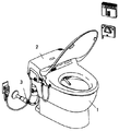
図1、図2に示すように、本発明の便器装置は、便器1、便器1に載置固定される局部洗浄装置2、壁面に設けられる止水栓3、便器洗浄装置4、止水栓3からの給水を局部洗浄装置2及び便器洗浄装置4へ分岐するための分岐栓5で構成される。なお、便器洗浄装置4の機構詳細については後述する。便器洗浄装置4は陶器製の便器1の後方に凹ませて設けた載置部1aに金属製若しくは樹脂製の載置プレート1b等を介してボルトで載置固定する。また、便器洗浄装置4は電動モータ4aによって電気的に駆動される。従って停電時等で給電が行なえない場合を考慮して手動操作部4bが設けられる。この手動操作部4bは便器1上面より下方に設けている。なお、便器洗浄装置4の一部は便器1上面よりも上方に突出させているが、これはバキュームブレーカーを設ける必要があるからである。また電動モータ4aへの給電及び制御を行なうための配線4cの先端に設けられるコネクタ4dを便器1に仮固定するための保持部1gを載置プレート1bに一体的に形成する。
【0019】
便器1の背面コーナー部には収納凹部13が設けられており、この収納凹部13に分岐栓5が設置される。便器へ分岐栓を固定する固定構造(固定部)を次に説明する。便器洗浄装置4の入水口4eには屈曲自在な連結管6の一端がワンタッチジョイント6aにより接続され、連結管6の他端は載置プレート1bに設けた連結管用貫通孔1cを貫通して垂下しており、その連結管6の他端には分岐栓5の出水口5fを袋ナット14で宙吊り状に接続固定する。これにより、便器1には便器洗浄機能部品としての便器洗浄装置4及び分岐栓5が一体化される。また、便器1上面に局部洗浄装置2を取付けるための取付プレート1dの取付を図19を用いて説明する。この取付プレート1dの両端は上方に折り曲げられ、中央に2個所に便器取付孔1hを設け、屈曲部1iにはネジ貫通用の孔を設けておく。
【0020】
座付きブッシュ34は、図に示すように、基部に取付けボルト38が嵌入される小孔35を設けた座36が付いており、先部に雌ねじ部32を中間にゴムで形成された弾性拡径部33を有している。座付きブッシュ34を固定孔1xに挿入し、座付きブッシュ34の基部の小孔35から取付けボルト38を挿入して先部の雌ねじ部32と螺合させると、取付ボルト38の回転に応じて座付きブッシュ34の先部の雌ねじ部32が昇降する。座36を固定して先部の雌ねじ部32を下方から上方に引き上げると、それにともなって中間の弾性拡径部33が重なり合って拡張する。その拡張した弾性拡径部33が固定孔1xの内部に押付けられることで取付けボルト38を便器取付孔1h及び固定孔1xに締着する。
【0021】
図3に示すように、建物躯体に用意された止水栓3に袋ナットで一体化された屈曲自在な供給管7の終端に設けたフランジ7aと宙吊りの分岐栓5の入水口に設けたフランジ5aとを弾性変形可能なワンタッチジョイント8で接続する。
【0022】
次に局部洗浄装置2を便器1へ載置固定するための手順を図4乃至図12及び図19を用いて説明する。
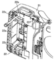
局部洗浄装置2は外郭を形成する上面カバー21、下面カバー22、下面カバー22に固定される機能部品23(調圧弁、逆止弁、電磁弁を一体化したバルブユニット、温水化するための熱交換ユニット、流量を調整する流量調整ユニット、局部へ温水を放出するためのノズルユニット、局部を乾燥するための乾燥ユニット、便器内の悪臭を吸込み無臭化するための脱臭ユニット、使用者を検知するための検知ユニット、各ユニットを制御するコントローラ等)から構成される。なお、機能部品23には便器洗浄装置4を制御するための便器洗浄用コントローラ23aが設けられる。下面カバー22の後方中央には、便器洗浄装置4の一部の便器1上面よりも上方に突出する部分を嵌装するために開口22aを設けている。また、開口22aの脇には給水管9を貫通するための給水管用開口22bを設けている。給水管用開口22bは給水管9より若干広めの幅で前後方向に長い形状として給水管9の自由度を左右方向の自由度を狭め、施工の際便器1と下面カバーとの間に給水管9が挟み込まれない様にしている。
【0023】
下面カバー22の後部裏面側に設けられたねじ頭係止手段22cに頭付きボルト24を装着した後、給水管9を便器1に設けた給水管用貫通孔1eに貫通垂下させ、頭付きボルト24を便器1の後側固定孔1fに挿入させて局部洗浄装置2を便器1に載せる。また、上面カバー21と下面カバー22との両側部間に設けられた隙間22f内に取付プレート1dの両端屈曲部1iを嵌合し、ネジ26を上面カバー21に設けたネジ挿入孔から屈曲部1iに設けたネジ挿入孔に挿入し、下面カバー両側面に固定されたナット21aに締着することで局部洗浄装置2の前側を固定する。なおネジ26の頭部分を隠蔽するための隠蔽カバー27をネジ26の頭部分若しくは上面カバー21に被せる。その後、後側固定孔1fを貫通した頭付きボルト24にナット25を螺合させて局部洗浄装置2を便器1に締着することで局部洗浄装置2の後側を固定一体化する。
【0024】
なお、局部洗浄装置2の後部裏面側に設けられたねじ頭係止手段22cは、図6に示すように、局部洗浄装置2の後部裏面側に切り欠いて形成された矩形状のボルト頭挿入部22dと、そのボルト頭挿入部22dの一部に設けられたU字状の係止溝22eとを有し、ヘッドが平面視して矩形状となっている頭付きボルト24の回り止めがなされている。これにより、頭付きボルト24は局部洗浄装置2の底部に確実に装着できる。
【0025】
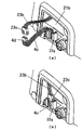
次に電気的な配線接続を図8及び図9を用いて説明する。図に示すように、上面カバー21の側部には施工用開口21bが設けられており、下面カバー22にはコネクタ保持部22gが一体的に形成されている。施工前にはこのコネクタ保持部22gには便器洗浄用コントローラからの電気配線23bの先端に設けられるコネクタ23cが保持されている。上述のように便器1に局部洗浄装置2を一体化した後、コネクタ保持部22gからコネクタ23c及び便器1のコネクタ保持部1gからコネクタ4dを開口21b外に引き出し、コネクタ23cとコネクタ4dとを接続する。その後、このコネクタ結合体をコネクタ保持部22gに差し込み、蓋28で開口21bを塞ぐ。蓋28の固定は下面カバー22にネジ固定することで行なう。
【0026】
次に、局部洗浄装置2と分岐栓5との接続について図10を用いて説明する。図に示すように、給水管9の先端に設けた取付フランジ9a及び分岐栓5の出水口5gに設けた取付フランジ5cとを突き合わせ、各フランジを弾性変形可能なワンタッチジョイント10で挟着接続する。この分岐栓5の全体を覆う隠蔽カバー11を分岐栓5にネジ等で固定し、分岐栓5を隠蔽する。なお、隠蔽カバー11には止水栓5dの操作部5bを露出させるための開口11aを設けている。なお、図12に示すように止水栓5dの操作部5bを除き分岐栓5は便器1の側面内に設けており、便器1の上面側の幅内に止水栓5dの操作部5bも設けたので、便器正面に立った使用者は便器上面の存在で正面からは操作部5bを見ることが出来ず、しゃがむ等姿勢を変更すれば視認可能となる。
ところで、給水管9と局部洗浄装置の入水口2aとは図11に示すようにワンタッチジョイント12を用いて入水口2aに対し回動自在に固定されている。従って、給水管9は分岐栓5への取付施工時に上下動し易くでき、接続作業性を向上することができる。
また、便器洗浄用コントローラ23aを垂直に配置し、最も高い機能部品とすることで上面カバー21に過負荷がかかった際(上面カバー21上に使用者が腰掛けた場合等)、このコントローラ23aで荷重を受けることにより上面カバー21の割れを防止することが出来る。
【0027】
次に、図を用いて便器洗浄装置4を説明する。
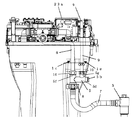
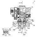
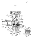
図13は実施例の便器洗浄装置4を便器本体85と共に概略的に表した概略図、図14はこの自閉弁および分配弁の断面図であり、図15は図14におけるA−A線断面図、図16は便器洗浄装置の概略構成を示すブロック図である。図17は手動操作部および便器洗浄装置の異常検出に係る実施例の概略図を示す。
【0028】
図13に示すように、便器本体85は、ボール部上縁のリム85aから洗浄水を吐出してボール部85bを洗浄するリム洗浄と、ボール部85b底部の吐出ノズル85cから洗浄水をトラップ配管85dに直接吐出して汚物搬送とトラップ部洗浄を行うジェット洗浄とを実行するように構成されている。そして、この便器本体85は、リム洗浄とジェット洗浄とを順次実行すべく便器洗浄装置4を備え、この便器洗浄装置4の外部出力ポート115aからは、リム85aに至るリム吐水配管86を外部出力ポート116aからは、吐出ノズル85cに至るジェット吐水配管87をそれぞれ接続して備える。この場合、リム85aと吐出ノズル85cに洗浄水を導くリム吐水配管86とジェット吐水配管87への洗浄水の分配供給は、以下にその構成を詳述する便器洗浄装置4によってなされ、こうした分配吐水により、洗浄吐水量、瞬間流量共に効率の良い便器洗浄を行うようにされている。
【0029】
図13ないし図14に示すように、便器洗浄装置4は、給水源(水道)からの一次側給水管103(前述の連結管6)が配管接続され自閉機能を有する自閉弁部102と、これと同期して洗浄水の分配供給を行うための分配弁部101とを積層集約して備え、分配弁部101の上端は、上記の各出力ポートを有する出力ポート部104と連結されている。本実施例において、便器洗浄装置4は、図17に示す手動操作部を図中矢印X方向に引張ることにより、自閉弁の開弁動作および、分配弁の動作が開始する。これにより、自閉作動ならびにこれと同期した分配作動を行うよう構成されている。以下に、本実施例の詳細を記述する。
【0030】
自閉弁部102は、一次側と二次側の差圧を利用して自閉作動を行うよう、以下の構成を備える。この自閉弁部102は、一次側給水管103が接続される管継ぎ手102aから洗浄装置本体JVに至る一次側給水路103aと、洗浄装置本体JV内の二次側通水路111aとを備え、この給水路と通水路の間に、ダイヤフラム弁110とパイロット弁114を有する。
【0031】
一次側給水路103は、洗浄装置本体JVにおいて、当該洗浄装置本体の内壁部分を環状に下方に隆起させて形成した給水弁座110aを取り囲むよう形成されている。よって、一次側給水路103aから流れ込んだ一次側洗浄水は、給水弁座110aの周囲において、ダイヤフラム弁110に下方向きに一次側圧力をかける。なお、一次側給水路103aには、管継ぎ手102aの下流で、洗浄装置本体JVの流入口近傍に減圧弁80,80a(定流量弁もしくは、流調弁でも可)が組み込まれているので、通常洗浄時には、給水弁座110a周囲には、定圧(定流量)の洗浄水が流れ込むことになる。なお、減圧弁80,80aは、洗浄装置本体JVに組み込まず、それよりも上流側の配管、もしくは止水栓等に配置しても良い。
【0032】
ダイヤフラム弁110は、洗浄装置本体JVの下端開口部に亘ってこの洗浄装置本体JVと背圧室を構成するケース102cとで挟持され、上記した一次側圧力を受けるダイヤフラム110bを有する。このダイヤフラム110bは、背圧室110cの側に上下動自在に上記したように挟持組み込みされており、ケース内部にあっては、背面のダイヤフラムサポート112と上面のリテーナ113で挟持・補強されている。このダイヤフラムサポート112は、リテーナ113とリベットにて固定されている。また、ダイヤフラム110bは、一次側と二次側の圧力バランスにより、付勢力が働き、その上面の平坦部を弁体として給水弁座110aに通常は当接着座させている。これにより、ダイヤフラム弁110は一次側給水路103aを給水弁座110aにてダイヤフラム110bにより常時閉鎖させている。この状態が、ダイヤフラム弁110の閉弁状態(止水状態)であり、便器洗浄装置4は通常この状態をとっている。なお、上下ガイド110dは、ダイヤフラムサポート112にその下端で係合して一体とされており、ダイヤフラム110bと共に上下動するようにされている。
【0033】
ダイヤフラム弁110は、上記のように閉弁状態にあるときでも一次側給水路103aと背圧室110cとの圧力均衡を図るべく、ダイヤフラム110bに一次側給水路103aと背圧室110cとを連通するブリード穴118を有する。このブリード穴118は、ダイヤフラム110bばかりでなくダイヤフラムサポート112とリテーナ113をも貫通して形成されており、一次側給水路103aの側から背圧室110cに常時、洗浄水を通過させる。この場合、このブリード穴118は、その穴径も小さく、内部には、後述のクリーニングピン119も配設されているので、一次側給水路103aの洗浄水は、背圧室110cに僅かずつしかブリード穴118を通って流入しない。そして、クリーニングピン119との関係において実質的に洗浄水の通過面積を決定するブリード穴118は、図15の要部拡大図に示すように、クリーニングピン119が常時穴内に存在する部分であり、ダイヤフラムサポート12に開けられたブリード穴118である。
【0034】
パイロット弁114は、上記のダイヤフラム弁110の開弁動作を起こさせるものであり、スプリング117の付勢力を上向きに直接受けるパイロット弁体114bと、ダイヤフラムサポート112の中央貫通孔の周囲を隆起させて形成したパイロット弁座114aと当接状態(着座状態)とされているので、パイロット弁114は、二次側通水路111aと背圧室110cとの間を閉鎖させている。この状態が、パイロット弁114の閉弁状態(止水状態)であり、便器洗浄装置4は、通常この状態を採っている。
【0035】
ここで、ダイヤフラム弁110の閉弁状態から開弁状態を経て、閉弁状態に至るまでの推移の様子について説明する。閉弁状態にあるパイロット弁114において、今、パイロット弁体114bがスプリング117の付勢力に抗して傾くと、パイロット弁座114aとパイロット弁体114bの当接着座がとけ、パイロット流路111bを介して背圧室110cと二次側通水路111aとが連通する。この場合、背圧室110c内は一次側給水路103aと同圧で二次側通水路111aより圧力が高いので、背圧室110c内の水は、パイロット流路111bを経て二次側通水路111aの側に排出される。すると、ダイヤフラム110bを挟んだ圧力の均衡が崩れて、このダイヤフラム110bは下向きに移動する。このため、ダイヤフラム弁110bは給水弁座110aが開いた開弁状態となり、一次側給水路103aから洗浄水が二次側通水路111aの側に流入する。
【0036】
その一方、パイロット弁体114bが正立状態に復帰すると、パイロット弁114bはパイロット弁座114aをこのパイロット弁体114bで閉じて閉弁する。この状態にあっては、ダイヤフラム110bのブリード穴118を介して、一次側給水路103aから背圧室110cに洗浄水が流れ込み、背圧室110c内は、この流れ込んだ洗浄水で満杯になる。すると、背圧室110cの圧力は一次側給水路103aの一次側給水圧力に等しくなり、ダイヤフラム110bは給水弁座110aに当接着座してダイヤフラム弁110bは止水状態となり、自閉弁部102での止水(自閉止水)がなされる。
【0037】
次に、上記のようにして、自閉弁部102にて、開弁が行われ、洗浄水が流入する分配弁部101について説明する。この分配弁部101は、自閉弁部102による上記の開弁時の開弁動作に同期して洗浄水の供給先を分配すべく以下の構成を有する。
【0038】
分配弁部101は、自閉弁機構部102の下流側に位置するようこの自閉弁部102と一体的に形成されており、上記したダイヤフラム弁110bから洗浄水の供給を受ける。分配弁部101は、二次側通水路111aに連通する洗浄水分配室130を洗浄装置本体JVで区画形成して備える。この洗浄水分配室130は、円柱形状で中空とされており、その内周壁面(分配室内周壁面)に、それぞれ上方に延びる出力ポート115、116が形成されている。この出力ポート115、116は外部出力ポート115aと116aとそれぞれ連通しているので、出力ポート116に流れ込んだ洗浄水は、リム吐水配管86を経てリム85aから吐出され、リム洗浄に用いられる。出力ポート116に流れ込んだ洗浄水は、ジェット吐水配管87を経て吐出ノズル85cから吐出され、ジェット洗浄に用いられる。
【0039】
分配弁部101は、洗浄水分配室130の内部に、分配室内周壁面と接触したまま摺動回転可能な回転ドラム121を有する。回転ドラム121は、この洗浄水分配室130に正逆回転自在に軸支された回転シャフト122と一体、あるいは、係合により構成されており、当該シャフトと共に回転する。この時、回転シャフト122は、横蓋50aでその一端が軸支されている。
【0040】
回転シャフト122は、洗浄水分配室130の内部においてカム部材122aを有し、このカム部材122aは回転シャフト122と一体的に正逆回転する。カム部材122aは、その回転に伴って、パイロット弁体114bのシャフト部と接触し当該弁体を周期して傾けるようにされている。このカム部材122aにより、上記した自閉弁部102における開弁動作が開始される。つまり、回転ドラム121やカム部材122aが初期状態(止水状態)にあるとき、図中時計方向に回転シャフト122が回転すると、カム部材122aはパイロット弁体114bを傾けるので、ダイヤフラム弁110bは上記したように開弁する。
【0041】
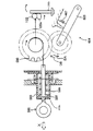
上記の構成において、自閉弁部102の自閉止水並びに分配弁機構部101の洗浄水分配のための駆動供給は、ギヤ列によって回転シャフト122に接続された手動操作弁用出力ギヤ590に連結された手動レバー591をケース端面593aとシャフト端面597aが突き当たるまで引張ることにより、回転駆動開始を行う。回転シャフト122にはゼンマイ、あるいは、ばね等の機械的駆動源を直接的、間接的に接続し、その駆動力をもって回転シャフト122を自閉弁102の閉止方向へ回転駆動すると同期させて、分配弁101の分配動作をさせる。その場合、回転シャフト122の回転速度調整のために、ダンパー604(オイルダンパー、エアーダンパー等)をギアで介して接続するか、もしくは、先負荷などで調節して速度制御を行ってもよい。
【0042】
上記構成において、ダンパー604(オイルダンパー、エアーダンパー等)を用いたダンパー機構で、アーム605,スプリング607を介させることにより、手動レバー591を引張る際には、ダンパー機構が解除され軽微な力で操作が可能である。尚、アーム605,スプリング607を介する替りに、1方向作用のダンパーを用いても良い。
この時、回転ドラム121は、回転シャフト122と共に時計回転するものの、回転開始当初は、出力ポート115を閉鎖したままである。よって、ダイヤフラム弁110bの開弁により、二次側通水路111aを経て一次給水路103aから洗浄水分配室130に流れ込んだ洗浄水は、出力ポート116を通過して上記したように吐出ノズル85cから吐出される。これにより、ジェット洗浄が実施される。
【0043】
回転シャフト122が更に回転を継続すると、パイロット弁体114bはカム部材122aにより傾いたままであるため、ダイヤフラム弁110は開弁状態を維持し、洗浄水分配室130には引き続き洗浄水が流入する。この回転継続の間において、回転ドラム121は出力ポート116を閉鎖して出力ポート115を開放するので、このようにポートの切り替えがなされた以降では、洗浄水分配室130の洗浄水は、出力ポート115を通過して、リム85aから吐出される。これにより、リム洗浄が実施される。このように、回転ドラム121によるポート切り替えにより、ジェット洗浄とリム洗浄が順次切替え実施される。しかも、この間に亘ってダイヤフラム弁110はパイロット弁体114bの傾きにより開弁状態を維持するので、リム洗浄とジェット洗浄は、途切れることなく連続して行われる。
【0044】
その一方、回転ドラム121が出力ポート116を閉鎖して出力ポート115を開放した状態から、回転シャフト122が更に時計方向に回転した初期状態に復帰すると、パイロット弁体114bは、カム部材122aから開放されて正立姿勢を採るので、ダイヤフラム弁110は上記したようにして開弁状態から閉弁状態となり、自閉弁機構部102では自閉止水される。尚、洗浄水分配室130および回転ドラム121を変更することによりリム−ジェット−リムのパターン洗浄も可能となる。
【0045】
図17に便器洗浄装置の異常検出に係る実施例を示す。
手動操作部4bである手動レバー591を引張ると力はケース部593に内蔵されたスプリング599を介して弁側出力ギヤ590に伝達され、最終的に回転シャフト122を回転させる。スプリング599はあらかじめ、自閉弁部,分配弁部の破壊力以下に設定されている。これによって、分配弁101,自閉弁102の凍結,ごみかみ等の異常を検知して未然に該部の破壊を防止する。
【0046】
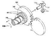
図18は便器洗浄装置の異常検出に係る別の実施例を示す。
回転シャフト122に接続された弁側出力軸586に第2ギヤ588を設け、対面した第1出力ギヤ587の背部にスプリング589を設けて、第2ギヤ588と第1出力ギヤ587に面圧を生じせしめている。スプリング589はあらかじめ、自閉弁部,分配弁部の破壊力以下に設定されている。これによって、分配弁101,自閉弁102の凍結,ごみかみ等の異常を検知して未然に該部の破壊を防止する。
尚、該スプリング589を形状記憶合金製とすれば、周囲温度が低くなった場合、自動的に第1出力ギヤ587への押力が解除し、分配弁101,自閉弁102の凍結,ごみかみ等の異常を検知して未然に該部の破壊を防止することが可能である。
【図面の簡単な説明】
【図1】 本発明の便器装置の外観斜視図である。
【図2】 同便器の外観斜視図である。
【図3】 同便器と給水管との取付手順を示す部分斜視図である。
【図4】 局部洗浄装置の便器本体への取付手順を説明するための分解斜視図である。
【図5】 局部洗浄装置を底面側からみた斜視図である。
【図6】 同局部洗浄装置の底面に設けたねじ頭係止手段を示す部分拡大斜視図である。
【図7】 便器に設けられた便器洗浄用モータの給電コネクタの仮固定構造を示す部分斜視図である。
【図8】 局部洗浄装置内のコントローラからの給電コネクタと便器洗浄用モータの給電コネクタとの接続手順を示す部分拡大斜視図である。
【図9】 同コネクタの接続を隠蔽するための蓋を取付を説明するための部分拡大斜視図である。
【図10】 局部洗浄装置に取付けられた給水管と、便器に取付られた分岐栓との接続手順を示す分解斜視図である。
【図11】 局部洗浄装置内での給水管の取付構造を示す斜視図である。
【図12】 局部洗浄装置のカバーを取り外した状態での便器装置の背面図である。
【図13】 実施例の便器洗浄装置4を便器本体85と共に概略的に表した概略図である。
【図14】 図13の自閉弁部および分配弁部の断面図である。
【図15】 図14におけるA−A線断面図である。
【図16】 便器洗浄装置4の概略構成を示すブロック図である。
【図17】 手動操作部および便器洗浄装置の異常検出に係る実施例の概略図である。
【図18】 便器洗浄装置の異常検出に係る別の実施例である。
【図19】 座付きブッシュと取付けボルトを示す斜視図である。
【符号の説明】
1 … 便器
1a … 載置部
1c … 連結管用貫通孔
1e … 給水管用貫通孔
2 … 局部洗浄装置
2a … 局部洗浄装置の入水口
4 … 便器洗浄装置
4b … 手動操作部(手動操作手段)
4e … 便器洗浄装置の入水口
5 … 分岐栓
5d … 止水弁
5f … 出水口
5g … 他出水口
6 … 連結管
9 … 給水管
10 … ワンタッチジョイント
13 … 収納凹部
21 … 上面カバー
22 … 下面カバー
22a … 開口
22b … 給水管用開口
85a … 便器リム
101 … 分配弁
102 … 自閉弁部
604 … ダンパー機構
[0001]
BACKGROUND OF THE INVENTION
The present invention relates to a toilet flushing device having a self-closing valve that discharges a predetermined amount of water by a manual operation used in a flush toilet and automatically closes the valve, and in particular covers the toilet flushing device and the local washing device as an integral cover. It relates to the toilet bowl covered.
[0002]
[Prior art]
As a conventional toilet flushing device, a flush valve that automatically stops water using a water pressure after discharging a certain amount of water is known, and is opened by manual operation, using the on-site water supply pressure, The valve automatically closes, and the manual lever is provided so as to protrude above the toilet rim surface.
Moreover, in the toilet device which covers the toilet cleaning device and the local cleaning device with an integral cover, a branch plug for independently supplying water to each of the toilet cleaning device and the local cleaning device is provided in the cover.
In addition, in a toilet device in which the toilet cleaning device and the local cleaning device are separated, the branch plug is exposed and the water supply pipe from the branch plug to the toilet cleaning device and the water supply tube from the branch plug to the local cleaning device are exposed. Was.
Each branch plug is provided with a stop cock for blocking water supply to the local cleaning device.
[0003]
[Problems to be solved by the invention]
However, in the conventional toilet cleaning device, it is necessary to provide a holding mechanism for holding the manual operation unit above the toilet rim surface. Particularly in the toilet device in which the conventional toilet cleaning device and the local cleaning device are covered with an integral cover, the toilet rim Although it is desirable to place the local cleaning parts above the surface and the toilet cleaning parts below and ship separately, the toilet cleaning parts should be stored and shipped on the toilet side for the holding mechanism. I couldn't.
Furthermore, when water leakage occurs in the local cleaning device due to a failure or the like, it is sufficient to close the stop cock for the local cleaning device provided on the branch plug in the cover or close the stop cock exposed in the toilet room. In order to close the faucet for the local cleaning device, it is necessary to remove the cover, and when the faucet in the toilet room is closed, the toilet itself cannot be used. . Furthermore, the installation space for the branch plug and a space for providing a dew condensation prevention mechanism or a dew condensation discharge mechanism in consideration of the condensation on the branch plug must be secured in the case, and the apparatus itself has been enlarged.
Further, in the toilet device in which the toilet cleaning device and the local cleaning device are separated, the above-described problems do not occur, but the water supply pipe is exposed, so the toilet room is messed up.
The present invention has been made in view of such circumstances, and an object thereof is to provide a toilet device with a toilet cleaning device that can be easily packed and shipped.
It is another object of the present invention to provide a toilet device that can clean the toilet room and can be easily stopped even when water leaks in the local cleaning device, and is more compact.
[0004]
[Means for solving the problem, operation and effect]
In order to solve the above-mentioned problem, in the invention of claim 1, in the toilet device integrally provided with the toilet cleaning device for cleaning the toilet by a self-closing valve which discharges a predetermined amount of water and automatically closes the valve, manual operation is performed. Since the manual operation means for opening the self-closing valve is provided and the manual operation means is provided below the upper surface of the toilet rim, all of the toilet plug parts can be assembled and shipped in the toilet bowl. The packing and shipping form can be separated from the local cleaning functional parts. Further, the invention of claim 1 further includes a local cleaning device for cleaning a local body part, and a lower surface cover for fixing and integrating functional parts of the local cleaning device is provided, and the toilet cleaning device is provided at the rear center of the lower surface cover. Since the opening for fitting is provided, it is possible to divide and package the functional parts of the local cleaning device and the functional parts of the toilet bowl, and an efficient distribution form can be achieved.
[0017]
DETAILED DESCRIPTION OF THE INVENTION
Hereinafter, embodiments of the present invention will be described in detail with reference to the drawings. 1 is an external perspective view of the toilet device of the present invention, FIG. 2 is an external perspective view of the toilet device, FIG. 3 is a partial perspective view showing a procedure for attaching the toilet device and a water supply pipe, and FIG. 4 is a toilet body of the local cleaning device FIG. 5 is a perspective view of the local cleaning device viewed from the bottom side, and FIG. 6 is a partially enlarged perspective view showing screw head locking means provided on the bottom surface of the local cleaning device. 7 is a partial perspective view showing a temporary fixing structure of a power supply connector of a toilet cleaning motor provided in the toilet, and FIG. 8 is a connection between the power supply connector from the controller in the local cleaning device and the power supply connector of the toilet cleaning motor. 9 is a partially enlarged perspective view showing the procedure, FIG. 9 is a partially enlarged perspective view for explaining the attachment of a cover for concealing the connection of the connector, and FIG. 10 is a water supply pipe attached to the local cleaning device and attached to the toilet. The exploded perspective view which shows the connection procedure with the made branch stopper, 11 is a perspective view showing a mounting structure of a water supply pipe in a private part washing device, FIG. 12 is a rear view of the toilet device with the cover removed of the local cleaning device. FIG. 19 is an exploded perspective view for explaining a procedure for attaching the attachment plate to the toilet body 84.
[0018]
As shown in FIGS. 1 and 2, a toilet device of the present invention includes a toilet 1, a local cleaning device 2 placed and fixed on the toilet 1, a stop cock 3 provided on a wall surface, a toilet cleaning device 4 and a stopcock. 3 is composed of a branch plug 5 for branching the water supply from 3 to the local cleaning device 2 and the toilet cleaning device 4. The details of the mechanism of the toilet bowl cleaning device 4 will be described later. The toilet bowl cleaning device 4 is mounted and fixed with bolts via a metal or resin mounting plate 1b or the like on a mounting portion 1a provided to be recessed behind the ceramic toilet bowl 1. Moreover, the toilet bowl washing | cleaning apparatus 4 is electrically driven by the electric motor 4a. Accordingly, the manual operation unit 4b is provided in consideration of a case where power cannot be supplied due to a power failure or the like. This manual operation part 4b is provided below the toilet bowl 1 upper surface. A part of the toilet bowl cleaning device 4 protrudes upward from the upper surface of the toilet bowl 1 because it is necessary to provide a vacuum breaker. Further, a holding portion 1g for temporarily fixing the connector 4d provided at the tip of the wiring 4c for supplying and controlling the electric motor 4a to the toilet 1 is integrally formed on the mounting plate 1b.
[0019]
A storage recess 13 is provided in the rear corner of the toilet 1, and the branch plug 5 is installed in the storage recess 13. Next, a fixing structure (fixing part) for fixing the branch plug to the toilet will be described. One end of a flexible connecting pipe 6 is connected to the water inlet 4e of the toilet bowl cleaning device 4 by a one-touch joint 6a, and the other end of the connecting pipe 6 hangs down through a connecting pipe through hole 1c provided in the mounting plate 1b. The water outlet 5f of the branch plug 5 is connected and fixed to the other end of the connecting pipe 6 with a cap nut 14 in a suspended manner. Thus, the toilet bowl cleaning device 4 and the branch plug 5 are integrated into the toilet bowl 1 as toilet bowl cleaning functional parts. Moreover, attachment of the attachment plate 1d for attaching the local cleaning device 2 to the upper surface of the toilet 1 will be described with reference to FIG. Both ends of the mounting plate 1d are bent upward, two toilet mounting holes 1h are provided at the center, and a screw penetration hole is provided in the bent portion 1i.
[0020]
As shown in the figure, the seated bush 34 has a seat 36 provided with a small hole 35 into which a mounting bolt 38 is inserted at the base, and an elastic diameter-expanded portion formed of rubber with a female screw portion 32 in the middle at the tip. A portion 33 is provided. When the seated bush 34 is inserted into the fixing hole 1x, and the mounting bolt 38 is inserted from the small hole 35 at the base of the seated bush 34 and screwed into the female screw portion 32 at the tip, the seated bush 34 is rotated according to the rotation of the mounting bolt 38. The female screw portion 32 at the tip of 34 moves up and down. When the seat 36 is fixed and the front female threaded portion 32 is pulled up from below, the intermediate elastic enlarged portion 33 overlaps and expands accordingly. The expanded elastic diameter-increased portion 33 is pressed into the fixing hole 1x, thereby fastening the mounting bolt 38 to the toilet mounting hole 1h and the fixing hole 1x.
[0021]
As shown in FIG. 3, a flange 7a provided at the end of a flexible supply pipe 7 integrated with a water stop cock 3 prepared in a building housing with a cap nut and a water inlet of a branching plug 5 suspended in the air. The flange 5a is connected by a one-touch joint 8 that can be elastically deformed.
[0022]
Next, a procedure for mounting and fixing the local cleaning device 2 on the toilet 1 will be described with reference to FIGS. 4 to 12 and FIG.
The local cleaning device 2 includes an upper surface cover 21, a lower surface cover 22, and a functional component 23 fixed to the lower surface cover 22 (a valve unit in which a pressure regulating valve, a check valve and an electromagnetic valve are integrated, heat for warming water) Replacement unit, flow rate adjustment unit for adjusting the flow rate, nozzle unit for discharging hot water to the local area, drying unit for drying the local area, deodorizing unit for sucking bad smell in the toilet bowl and deodorizing, detecting the user For example, a detection unit and a controller for controlling each unit). The functional component 23 is provided with a toilet cleaning controller 23a for controlling the toilet cleaning device 4. An opening 22 a is provided at the rear center of the lower surface cover 22 in order to fit a portion protruding upward from the upper surface of a part of the toilet bowl 1 of the toilet bowl cleaning device 4. Further, a water supply pipe opening 22b for penetrating the water supply pipe 9 is provided beside the opening 22a. The water supply pipe opening 22b is slightly wider than the water supply pipe 9 and has a shape that is long in the front-rear direction, so that the degree of freedom of the water supply pipe 9 is reduced in the left-right direction. Is not caught.
[0023]
After the head bolt 24 is attached to the screw head locking means 22c provided on the rear rear surface side of the lower surface cover 22, the water supply pipe 9 is dropped through the water supply pipe through hole 1e provided in the toilet 1 and the head bolt 24 Is inserted into the rear fixing hole 1 f of the toilet 1 and the local cleaning device 2 is placed on the toilet 1. Further, the bent portions 1i of both ends of the mounting plate 1d are fitted into a gap 22f provided between both side portions of the upper surface cover 21 and the lower surface cover 22, and the screw 26 is bent from the screw insertion hole provided in the upper surface cover 21. The front side of the local cleaning device 2 is fixed by being inserted into a screw insertion hole provided in 1i and fastened to nuts 21a fixed to both side surfaces of the lower surface cover. A concealing cover 27 for concealing the head portion of the screw 26 is placed on the head portion of the screw 26 or the upper surface cover 21. Thereafter, the nut 25 is screwed into the headed bolt 24 penetrating the rear fixing hole 1f, and the local cleaning device 2 is fastened to the toilet 1 so that the rear side of the local cleaning device 2 is fixed and integrated.
[0024]
In addition, as shown in FIG. 6, the screw head locking means 22c provided on the rear back surface side of the local cleaning device 2 is inserted into a rectangular bolt head formed by cutting out on the rear back surface side of the local cleaning device 2. A head-shaped bolt 24 having a rectangular shape in plan view, having a portion 22d and a U-shaped locking groove 22e provided in a part of the bolt head insertion portion 22d. Has been made. Thereby, the headed bolt 24 can be securely attached to the bottom of the local cleaning device 2.
[0025]
Next, electrical wiring connection will be described with reference to FIGS. As shown in the drawing, a construction opening 21 b is provided in a side portion of the upper surface cover 21, and a connector holding portion 22 g is integrally formed in the lower surface cover 22. Prior to construction, the connector holding portion 22g holds the connector 23c provided at the tip of the electrical wiring 23b from the toilet bowl cleaning controller. After the local cleaning device 2 is integrated with the toilet 1 as described above, the connector 23c is pulled out from the connector holding portion 22g and the connector 4d from the connector holding portion 1g of the toilet 1 to the outside of the opening 21b, and the connector 23c and the connector 4d are connected. To do. Thereafter, the connector assembly is inserted into the connector holding portion 22g, and the opening 21b is closed with the lid 28. The lid 28 is fixed by screwing it to the lower surface cover 22.
[0026]
Next, the connection between the local cleaning device 2 and the branch plug 5 will be described with reference to FIG. As shown in the figure, the mounting flange 9a provided at the tip of the water supply pipe 9 and the mounting flange 5c provided at the water outlet 5g of the branch plug 5 are abutted and each flange is clamped and connected by a one-touch joint 10 that can be elastically deformed. . A concealing cover 11 covering the entire branch plug 5 is fixed to the branch plug 5 with a screw or the like to conceal the branch plug 5. The concealing cover 11 is provided with an opening 11a for exposing the operation portion 5b of the water stop cock 5d. In addition, as shown in FIG. 12, the branch plug 5 is provided in the side surface of the toilet bowl 1 except the operation part 5b of the stop cock 5d, and the operation part 5b of the stop cock 5d is also within the width | variety of the upper surface side of the toilet bowl 1. Since it is provided, a user standing in front of the toilet bowl cannot see the operation unit 5b from the front due to the presence of the upper face of the toilet bowl, and can be visually recognized by changing the posture such as squatting.
By the way, as shown in FIG. 11, the water supply pipe 9 and the water inlet 2a of the local cleaning apparatus are fixed to the water inlet 2a by using a one-touch joint 12. Therefore, the water supply pipe 9 can be easily moved up and down at the time of installation work on the branch plug 5 and the connection workability can be improved.
In addition, when the toilet bowl cleaning controller 23a is vertically arranged and the highest functional component is used, when the upper cover 21 is overloaded (for example, when a user sits on the upper cover 21), the controller 23a By receiving the load, the top cover 21 can be prevented from cracking.
[0027]
Next, the toilet bowl cleaning device 4 will be described with reference to the drawings.
13 is a schematic view schematically showing the toilet cleaning device 4 of the embodiment together with the toilet body 85, FIG. 14 is a sectional view of the self-closing valve and the distributing valve, and FIG. 15 is a sectional view taken along line AA in FIG. FIG. 16 and FIG. 16 are block diagrams showing a schematic configuration of the toilet bowl cleaning apparatus. FIG. 17 is a schematic diagram of an embodiment relating to abnormality detection of the manual operation unit and the toilet bowl cleaning device.
[0028]
As shown in FIG. 13, the toilet body 85 has a rim cleaning for discharging the cleaning water from the rim 85a at the upper edge of the ball portion to clean the ball portion 85b, and the trapping pipe for the cleaning water from the discharge nozzle 85c at the bottom of the ball portion 85b. It is configured to execute jet cleaning that directly discharges to 85d and performs filth transport and trap portion cleaning. The toilet body 85 includes the toilet cleaning device 4 for sequentially performing rim cleaning and jet cleaning, and an external output port 115a of the toilet cleaning device 4 outputs a rim water discharge pipe 86 leading to the rim 85a to an external output. From the port 116a, a jet water discharge pipe 87 reaching the discharge nozzle 85c is connected and provided. In this case, the supply of the wash water to the rim water discharge pipe 86 and the jet water discharge pipe 87 for guiding the wash water to the rim 85a and the discharge nozzle 85c is performed by the toilet flushing device 4 described in detail below. Therefore, the toilet flushing is performed efficiently both in the amount of water discharged and the instantaneous flow rate.
[0029]
As shown in FIGS. 13 to 14, the toilet bowl cleaning device 4 includes a self-closing valve portion 102 having a self-closing function, in which a primary-side water supply pipe 103 (the above-described connecting pipe 6) from a water supply source (water supply) is piped. In addition, the distribution valve unit 101 for distributing and supplying the washing water in synchronization with this is provided in an integrated manner, and the upper end of the distribution valve unit 101 is connected to the output port unit 104 having each output port described above. Yes. In the present embodiment, the toilet bowl cleaning device 4 starts the opening operation of the self-closing valve and the operation of the distributing valve by pulling the manual operation unit shown in FIG. 17 in the direction of the arrow X in the drawing. Thereby, it is comprised so that self-closing operation | movement and the distribution operation | movement synchronized with this may be performed. Details of this embodiment will be described below.
[0030]
The self-closing valve unit 102 has the following configuration so as to perform a self-closing operation using a differential pressure between the primary side and the secondary side. The self-closing valve portion 102 includes a primary side water supply path 103a from the pipe joint 102a to which the primary side water supply pipe 103 is connected to the cleaning apparatus body JV, and a secondary side water passage 111a in the cleaning apparatus body JV. A diaphragm valve 110 and a pilot valve 114 are provided between the water supply passage and the water passage.
[0031]
The primary side water supply path 103 is formed so as to surround a water supply valve seat 110a formed by raising an inner wall portion of the cleaning device main body downward in an annular shape in the cleaning device main body JV. Therefore, the primary side wash water that has flowed from the primary side water supply passage 103a applies a primary side pressure downward to the diaphragm valve 110 around the water supply valve seat 110a. In addition, since the pressure reducing valves 80 and 80a (constant flow valves or flow control valves are also possible) are incorporated in the primary side water supply passage 103a in the vicinity of the inlet of the cleaning device main body JV downstream of the pipe joint 102a. During normal cleaning, cleaning water with a constant pressure (a constant flow rate) flows around the water supply valve seat 110a. Note that the pressure reducing valves 80 and 80a may not be incorporated in the cleaning apparatus main body JV, but may be arranged in a pipe upstream of the cleaning apparatus, a stop cock, or the like.
[0032]
The diaphragm valve 110 has a diaphragm 110b that is sandwiched between the cleaning device main body JV and the case 102c constituting the back pressure chamber across the lower end opening of the cleaning device main body JV, and receives the primary pressure described above. The diaphragm 110b is sandwiched and incorporated in the back pressure chamber 110c side so as to be movable up and down as described above. Inside the case, the diaphragm 110b is sandwiched and reinforced by the diaphragm support 112 on the back surface and the retainer 113 on the top surface. . The diaphragm support 112 is fixed to the retainer 113 with rivets. Further, the diaphragm 110b is energized by the pressure balance between the primary side and the secondary side, and is usually bonded to the water supply valve seat 110a with the flat portion on the upper surface as a valve body. Thereby, the diaphragm valve 110 always closes the primary side water supply path 103a by the diaphragm 110b in the water supply valve seat 110a. This state is a closed state (water-stopped state) of the diaphragm valve 110, and the toilet bowl cleaning device 4 normally takes this state. The upper and lower guides 110d are integrated with the diaphragm support 112 at the lower end thereof, and are moved up and down together with the diaphragm 110b.
[0033]
Diaphragm valve 110 communicates primary side water supply passage 103a and back pressure chamber 110c with diaphragm 110b in order to balance the pressure between primary water supply passage 103a and back pressure chamber 110c even when the valve is closed as described above. A bleed hole 118 is provided. The bleed hole 118 is formed not only through the diaphragm 110b but also through the diaphragm support 112 and the retainer 113, and always allows cleaning water to pass from the primary water supply passage 103a side to the back pressure chamber 110c. In this case, the diameter of the bleed hole 118 is small, and a cleaning pin 119 (described later) is also disposed therein, so that the cleaning water in the primary side water supply passage 103a is only little by little in the back pressure chamber 110c. It does not flow through the bleed hole 118. The bleed hole 118 that substantially determines the passage area of the cleaning water in relation to the cleaning pin 119 is a portion where the cleaning pin 119 is always present in the hole as shown in the enlarged view of the main part in FIG. A bleed hole 118 is formed in the diaphragm support 12.
[0034]
The pilot valve 114 causes the valve opening operation of the diaphragm valve 110 described above, and the pilot valve body 114b that directly receives the urging force of the spring 117 and the central through hole of the diaphragm support 112 are raised. Since the formed pilot valve seat 114a is in a contact state (sitting state), the pilot valve 114 closes the space between the secondary side water passage 111a and the back pressure chamber 110c. This state is a closed state (water stop state) of the pilot valve 114, and the toilet bowl cleaning device 4 normally takes this state.
[0035]
Here, a transition state from the closed state of the diaphragm valve 110 to the closed state through the opened state will be described. In the pilot valve 114 in the closed state, when the pilot valve body 114b is tilted against the urging force of the spring 117, the contact seat between the pilot valve seat 114a and the pilot valve body 114b breaks, and the pilot flow path 111b is opened. The back pressure chamber 110c and the secondary water passage 111a communicate with each other. In this case, since the pressure in the back pressure chamber 110c is the same as that in the primary side water supply passage 103a and is higher than that in the secondary side water passage 111a, the water in the back pressure chamber 110c passes through the pilot flow passage 111b to the secondary side water passage. It is discharged to the 111a side. Then, the pressure balance across the diaphragm 110b is lost, and the diaphragm 110b moves downward. For this reason, the diaphragm valve 110b becomes an open state in which the water supply valve seat 110a is opened, and the wash water flows from the primary side water supply path 103a to the secondary side water passage 111a side.
[0036]
On the other hand, when the pilot valve body 114b returns to the upright state, the pilot valve 114b closes the pilot valve seat 114a with the pilot valve body 114b. In this state, cleaning water flows from the primary water supply passage 103a into the back pressure chamber 110c through the bleed hole 118 of the diaphragm 110b, and the back pressure chamber 110c is filled with the flowing cleaning water. Then, the pressure in the back pressure chamber 110c becomes equal to the primary water supply pressure of the primary water supply passage 103a, the diaphragm 110b is in contact with the water supply valve seat 110a, the diaphragm valve 110b is in a water stop state, and the self-closing valve portion 102 is closed. Water stop (self-closing water) is made at.
[0037]
Next, as described above, the self-closing valve portion 102 will be described and the distribution valve portion 101 into which wash water flows will be described. The distribution valve unit 101 has the following configuration in order to distribute the supply destination of cleaning water in synchronization with the valve opening operation at the time of the valve opening by the self-closing valve unit 102.
[0038]
The distribution valve unit 101 is formed integrally with the self-closing valve unit 102 so as to be positioned downstream of the self-closing valve unit 102, and receives the supply of cleaning water from the diaphragm valve 110b. The distribution valve unit 101 includes a cleaning water distribution chamber 130 that communicates with the secondary side water passage 111a and is partitioned by the cleaning device main body JV. The washing water distribution chamber 130 is cylindrical and hollow, and output ports 115 and 116 extending upward are formed on the inner peripheral wall surface (distribution chamber peripheral wall surface), respectively. Since the output ports 115 and 116 communicate with the external output ports 115a and 116a, the cleaning water flowing into the output port 116 is discharged from the rim 85a through the rim water discharge pipe 86 and used for rim cleaning. The washing water flowing into the output port 116 is discharged from the discharge nozzle 85c through the jet water discharge pipe 87 and used for jet washing.
[0039]
The distribution valve unit 101 has a rotating drum 121 that can slide and rotate while being in contact with the peripheral wall surface of the distribution chamber inside the cleaning water distribution chamber 130. The rotating drum 121 is configured integrally with or engaged with a rotating shaft 122 that is pivotally supported in the cleaning water distribution chamber 130 so as to rotate forward and backward, and rotates together with the shaft. At this time, one end of the rotating shaft 122 is pivotally supported by the horizontal lid 50a.
[0040]
The rotating shaft 122 has a cam member 122 a inside the cleaning water distribution chamber 130, and the cam member 122 a rotates forward and backward integrally with the rotating shaft 122. As the cam member 122a rotates, the cam member 122a comes into contact with the shaft portion of the pilot valve body 114b and tilts the valve body periodically. The cam member 122a starts the valve opening operation in the self-closing valve portion 102 described above. That is, when the rotary drum 121 and the cam member 122a are in the initial state (water stoppage state), when the rotary shaft 122 rotates in the clockwise direction in the drawing, the cam member 122a tilts the pilot valve body 114b, so that the diaphragm valve 110b It opens as it did.
[0041]
In the above configuration, the drive supply for the self-closing water of the self-closing valve portion 102 and the cleaning water distribution of the distribution valve mechanism portion 101 is coupled to the manually operated valve output gear 590 connected to the rotary shaft 122 by a gear train. The driven lever 591 is pulled until the case end surface 593a and the shaft end surface 597a come into contact with each other, thereby starting rotational driving. A mechanical drive source such as a spring or a spring is directly or indirectly connected to the rotary shaft 122, and the rotary shaft 122 is synchronized with the driving force of the rotary shaft 122 in the closing direction of the self-closing valve 102. The dispensing operation of the valve 101 is performed. In that case, in order to adjust the rotation speed of the rotating shaft 122, the damper 604 (oil damper, air damper, etc.) may be connected via a gear, or the speed may be controlled by adjusting with a preload or the like.
[0042]
In the above configuration, when the manual lever 591 is pulled by the damper mechanism using the damper 604 (oil damper, air damper, etc.) and the arm 605 and the spring 607, the damper mechanism is released with a slight force. Operation is possible. Instead of the arm 605 and the spring 607, a unidirectional damper may be used.
At this time, the rotating drum 121 rotates clockwise together with the rotating shaft 122, but the output port 115 remains closed at the beginning of the rotation. Therefore, by opening the diaphragm valve 110b, the wash water flowing from the primary water supply passage 103a into the wash water distribution chamber 130 via the secondary water passage 111a passes through the output port 116 and is discharged from the discharge nozzle 85c as described above. Discharged. Thereby, jet cleaning is performed.
[0043]
When the rotating shaft 122 continues to rotate further, the pilot valve body 114b remains tilted by the cam member 122a, so that the diaphragm valve 110 maintains the open state, and the washing water continues to flow into the washing water distribution chamber 130. While the rotation continues, the rotary drum 121 closes the output port 116 and opens the output port 115. Therefore, after the port is switched in this way, the cleaning water in the cleaning water distribution chamber 130 is supplied to the output port 115. It passes through 115 and is discharged from the rim 85a. Thereby, rim cleaning is performed. As described above, the jet cleaning and the rim cleaning are sequentially switched by the port switching by the rotating drum 121. In addition, since the diaphragm valve 110 maintains the valve open state during this period due to the inclination of the pilot valve body 114b, the rim cleaning and the jet cleaning are continuously performed without interruption.
[0044]
On the other hand, when the rotary drum 121 closes the output port 116 and opens the output port 115, and returns to the initial state where the rotary shaft 122 further rotates clockwise, the pilot valve body 114b is released from the cam member 122a. As a result, the diaphragm valve 110 changes from the open state to the closed state as described above, and the self-closing mechanism 102 is self-closing water. The rim-jet-rim pattern can be cleaned by changing the cleaning water distribution chamber 130 and the rotating drum 121.
[0045]
FIG. 17 shows an embodiment relating to abnormality detection of the toilet bowl cleaning device.
When the manual lever 591 which is the manual operation unit 4b is pulled, the force is transmitted to the valve-side output gear 590 via the spring 599 incorporated in the case unit 593, and finally the rotating shaft 122 is rotated. The spring 599 is set in advance below the destructive force of the self-closing valve portion and the distribution valve portion. As a result, abnormalities such as freezing and garbage in the distribution valve 101 and the self-closing valve 102 are detected to prevent the destruction of the portion.
[0046]
FIG. 18 shows another embodiment relating to abnormality detection of the toilet bowl cleaning device.
A second gear 588 is provided on the valve-side output shaft 586 connected to the rotating shaft 122, and a spring 589 is provided on the back of the first output gear 587 that faces the second gear 588 and the first output gear 587. It is generated. The spring 589 is set in advance below the destructive force of the self-closing valve portion and the distributing valve portion. As a result, abnormalities such as freezing and garbage in the distribution valve 101 and the self-closing valve 102 are detected to prevent the destruction of the portion.
If the spring 589 is made of a shape memory alloy, the pressing force to the first output gear 587 is automatically released when the ambient temperature becomes low, and the distribution valve 101 and the self-closing valve 102 are frozen. It is possible to detect an abnormality such as a bite and prevent the destruction of the portion in advance.
[Brief description of the drawings]
FIG. 1 is an external perspective view of a toilet device according to the present invention.
FIG. 2 is an external perspective view of the toilet.
FIG. 3 is a partial perspective view showing a procedure for attaching the toilet bowl and a water supply pipe.
FIG. 4 is an exploded perspective view for explaining a procedure for attaching the local cleaning device to the toilet body.
FIG. 5 is a perspective view of the local cleaning device as seen from the bottom side.
FIG. 6 is a partially enlarged perspective view showing screw head locking means provided on the bottom surface of the local cleaning device.
FIG. 7 is a partial perspective view showing a temporary fixing structure of a power feeding connector of a toilet flushing motor provided in the toilet bowl.
FIG. 8 is a partially enlarged perspective view showing a connection procedure between a power supply connector from a controller in the local cleaning device and a power supply connector of a toilet cleaning motor.
FIG. 9 is a partially enlarged perspective view for explaining attachment of a lid for concealing the connection of the connector.
FIG. 10 is an exploded perspective view showing a connection procedure between a water supply pipe attached to the local cleaning device and a branch plug attached to the toilet bowl.
FIG. 11 is a perspective view showing a water supply pipe mounting structure in the local cleaning device.
FIG. 12 is a rear view of the toilet device with the cover of the local cleaning device removed.
13 is a schematic view schematically showing the toilet bowl cleaning device 4 of the embodiment together with a toilet body 85. FIG.
14 is a cross-sectional view of the self-closing valve portion and the distribution valve portion of FIG.
15 is a cross-sectional view taken along line AA in FIG.
16 is a block diagram showing a schematic configuration of the toilet bowl cleaning device 4. FIG.
FIG. 17 is a schematic view of an embodiment relating to abnormality detection of a manual operation unit and a toilet bowl cleaning device.
FIG. 18 is another example relating to abnormality detection of the toilet bowl cleaning device.
FIG. 19 is a perspective view showing a seated bush and a mounting bolt.
[Explanation of symbols]
DESCRIPTION OF SYMBOLS 1 ... Toilet 1a ... Placement part 1c ... Through-hole 1e for connection pipes ... Through-hole 2 for water supply pipes ... Local washing apparatus 2a ... Water inlet 4 of a local washing apparatus ... Toilet washing apparatus 4b ... Manual operation part (manual operation means)
4e: Water inlet 5 of toilet bowl cleaning device 5 ... Branch plug 5d ... Water stop valve 5f ... Water outlet 5g ... Other water outlet 6 ... Connection pipe 9 ... Water supply pipe 10 ... One-touch joint 13 ... Storage recess 21 ... Top cover 22 ... Bottom cover 22a ... Opening 22b ... Water supply pipe opening 85a ... Toilet rim 101 ... Distributing valve 102 ... Self-closing valve portion 604 ... Damper mechanism

Claims (1)

所定量の水を吐出し自動的に閉弁する自閉弁によって便器を洗浄する便器洗浄装置を一体的に備えた便器装置において、手動操作により前記自閉弁を開弁動作させる手動操作手段を備え、該手動操作手段を便器リム上面よりも下方に設け、更に人体局部を洗浄する局部洗浄装置を備え、前記局部洗浄装置の機能部品を固定一体化する下面カバーを設け、該下面カバーの後方中央には前記便器洗浄装置を嵌装する開口を設けたことを特徴とする便器装置。In a toilet apparatus integrally provided with a toilet flushing apparatus that flushes a toilet bowl by a self-closing valve that discharges a predetermined amount of water and automatically closes, manual operation means for opening the self-closing valve by manual operation is provided. Provided with the manual operation means below the upper surface of the toilet rim , further provided with a local cleaning device for cleaning a local body part, provided with a lower surface cover for fixing and integrating functional parts of the local cleaning device, and behind the lower surface cover A toilet device characterized in that an opening for fitting the toilet cleaning device is provided in the center .
JP2002075278A 2002-03-18 2002-03-18 Toilet device Expired - Fee Related JP4132895B2 (en)

Priority Applications (1)

Application Number Priority Date Filing Date Title
JP2002075278A JP4132895B2 (en) 2002-03-18 2002-03-18 Toilet device

Applications Claiming Priority (1)

Application Number Priority Date Filing Date Title
JP2002075278A JP4132895B2 (en) 2002-03-18 2002-03-18 Toilet device

Publications (3)

Publication Number Publication Date
JP2003268855A JP2003268855A (en) 2003-09-25
JP2003268855A5 JP2003268855A5 (en) 2005-09-08
JP4132895B2 true JP4132895B2 (en) 2008-08-13

Family

ID=29204395

Family Applications (1)

Application Number Title Priority Date Filing Date
JP2002075278A Expired - Fee Related JP4132895B2 (en) 2002-03-18 2002-03-18 Toilet device

Country Status (1)

Country Link
JP (1) JP4132895B2 (en)

Families Citing this family (6)

* Cited by examiner, † Cited by third party
Publication number Priority date Publication date Assignee Title
TW200745421A (en) 2006-02-13 2007-12-16 Toto Ltd Sanitary flushing device and toilet device
JP5234480B2 (en) * 2007-03-28 2013-07-10 Toto株式会社 Concealment structure of water supply hose to toilet seat
JP5197160B2 (en) * 2008-05-28 2013-05-15 株式会社Lixil Toilet seat device
JP5724803B2 (en) * 2011-09-29 2015-05-27 Toto株式会社 Flush toilet equipment
JP6655950B2 (en) * 2015-07-08 2020-03-04 株式会社Lixil Toilet bowl cleaning equipment
JP7433904B2 (en) 2019-12-27 2024-02-20 株式会社Lixil toilet device

Family Cites Families (9)

* Cited by examiner, † Cited by third party
Publication number Priority date Publication date Assignee Title
JPH01116127A (en) * 1987-10-28 1989-05-09 Toto Ltd Water closet
JPH049479U (en) * 1990-05-08 1992-01-28
JPH10331230A (en) * 1997-06-04 1998-12-15 Toto Ltd Flush type stool
JP2000193115A (en) * 1998-05-11 2000-07-14 Toto Ltd Self-closing cock device
JP2001152530A (en) * 1999-11-29 2001-06-05 Inax Corp Tankless toilet stool
JP3791587B2 (en) * 2000-06-09 2006-06-28 株式会社Inax Western style flush toilet
JP2001323535A (en) * 2000-05-12 2001-11-22 Toto Ltd Toilet stool apparatus
JP3776684B2 (en) * 2000-06-21 2006-05-17 株式会社Inax Western style flush toilet
JP2002129628A (en) * 2000-10-27 2002-05-09 Matsushita Electric Works Ltd Flush toilet bowl

Also Published As

Publication number Publication date
JP2003268855A (en) 2003-09-25

Similar Documents

Publication Publication Date Title
US7232110B2 (en) Automatic flush actuation apparatus
US6840496B2 (en) Automatic flush actuation apparatus
US7510166B2 (en) Automatic flush actuation apparatus
WO2001098593A1 (en) Method of feeding water to stop valve, stop valve for water closet, water feeding device for washing water closet, tank-less western water closet, and western water closet, flow path switching device, and water closet
JP4132895B2 (en) Toilet device
JP3707295B2 (en) Toilet with self-closing faucet
US6871835B2 (en) Flow control valve with automatic shutoff capability
JP3719577B2 (en) Pressure chamber valve
US8152135B2 (en) Automatic flush actuation apparatus
JP4109472B2 (en) Toilet device
US6845961B2 (en) Automatic flush actuation apparatus
JP3921110B2 (en) Function unit mounting mechanism on the toilet body
JP2000297454A (en) Toilet stool washing device
JP2003268839A (en) Functional portion attached mechanism to main body of water closet
JP2003268854A (en) Stool device
JPH08144346A (en) Switch valve
JP2005213906A (en) Washing water tank for closet
JP2001295352A (en) Water closet
JP3930744B2 (en) Water discharge device
US1069559A (en) Valve for water-closets.
JP2002294806A (en) Vacuum breaker for sanitary washing device
JPH10204949A (en) Automatic water tap unit
JP2000160664A (en) Water leakage prevention device for toilet
KR20140135637A (en) A toilet stool for economize water
JP2003275146A (en) Toilet device

Legal Events

Date Code Title Description
A521 Written amendment

Free format text: JAPANESE INTERMEDIATE CODE: A523

Effective date: 20050317

A621 Written request for application examination

Free format text: JAPANESE INTERMEDIATE CODE: A621

Effective date: 20050317

A977 Report on retrieval

Free format text: JAPANESE INTERMEDIATE CODE: A971007

Effective date: 20061128

A131 Notification of reasons for refusal

Free format text: JAPANESE INTERMEDIATE CODE: A131

Effective date: 20061219

A521 Written amendment

Free format text: JAPANESE INTERMEDIATE CODE: A523

Effective date: 20070209

RD02 Notification of acceptance of power of attorney

Free format text: JAPANESE INTERMEDIATE CODE: A7422

Effective date: 20070209

A131 Notification of reasons for refusal

Free format text: JAPANESE INTERMEDIATE CODE: A131

Effective date: 20070814

TRDD Decision of grant or rejection written
A01 Written decision to grant a patent or to grant a registration (utility model)

Free format text: JAPANESE INTERMEDIATE CODE: A01

Effective date: 20080507

A01 Written decision to grant a patent or to grant a registration (utility model)

Free format text: JAPANESE INTERMEDIATE CODE: A01

A61 First payment of annual fees (during grant procedure)

Free format text: JAPANESE INTERMEDIATE CODE: A61

Effective date: 20080602

FPAY Renewal fee payment (event date is renewal date of database)

Free format text: PAYMENT UNTIL: 20110606

Year of fee payment: 3

R150 Certificate of patent or registration of utility model

Free format text: JAPANESE INTERMEDIATE CODE: R150

Ref document number: 4132895

Country of ref document: JP

Free format text: JAPANESE INTERMEDIATE CODE: R150

A521 Written amendment

Free format text: JAPANESE INTERMEDIATE CODE: A523

Effective date: 20050317

FPAY Renewal fee payment (event date is renewal date of database)

Free format text: PAYMENT UNTIL: 20130606

Year of fee payment: 5

FPAY Renewal fee payment (event date is renewal date of database)

Free format text: PAYMENT UNTIL: 20140606

Year of fee payment: 6

LAPS Cancellation because of no payment of annual fees