EP2005776B1 - Funkkommunikationsvorrichtung - Google Patents
Funkkommunikationsvorrichtung Download PDFInfo
- Publication number
- EP2005776B1 EP2005776B1 EP07738776.9A EP07738776A EP2005776B1 EP 2005776 B1 EP2005776 B1 EP 2005776B1 EP 07738776 A EP07738776 A EP 07738776A EP 2005776 B1 EP2005776 B1 EP 2005776B1
- Authority
- EP
- European Patent Office
- Prior art keywords
- noise
- radio communication
- radio
- signal
- cca
- Prior art date
- Legal status (The legal status is an assumption and is not a legal conclusion. Google has not performed a legal analysis and makes no representation as to the accuracy of the status listed.)
- Ceased
Links
Images


Classifications
-
- H—ELECTRICITY
- H04—ELECTRIC COMMUNICATION TECHNIQUE
- H04B—TRANSMISSION
- H04B1/00—Details of transmission systems, not covered by a single one of groups H04B3/00 - H04B13/00; Details of transmission systems not characterised by the medium used for transmission
- H04B1/06—Receivers
- H04B1/10—Means associated with receiver for limiting or suppressing noise or interference
- H04B1/1027—Means associated with receiver for limiting or suppressing noise or interference assessing signal quality or detecting noise/interference for the received signal
-
- H—ELECTRICITY
- H04—ELECTRIC COMMUNICATION TECHNIQUE
- H04B—TRANSMISSION
- H04B7/00—Radio transmission systems, i.e. using radiation field
- H04B7/24—Radio transmission systems, i.e. using radiation field for communication between two or more posts
-
- G—PHYSICS
- G06—COMPUTING OR CALCULATING; COUNTING
- G06F—ELECTRIC DIGITAL DATA PROCESSING
- G06F13/00—Interconnection of, or transfer of information or other signals between, memories, input/output devices or central processing units
- G06F13/10—Program control for peripheral devices
-
- H—ELECTRICITY
- H04—ELECTRIC COMMUNICATION TECHNIQUE
- H04W—WIRELESS COMMUNICATION NETWORKS
- H04W28/00—Network traffic management; Network resource management
- H04W28/02—Traffic management, e.g. flow control or congestion control
- H04W28/04—Error control
-
- H—ELECTRICITY
- H04—ELECTRIC COMMUNICATION TECHNIQUE
- H04W—WIRELESS COMMUNICATION NETWORKS
- H04W24/00—Supervisory, monitoring or testing arrangements
- H04W24/10—Scheduling measurement reports ; Arrangements for measurement reports
-
- H—ELECTRICITY
- H04—ELECTRIC COMMUNICATION TECHNIQUE
- H04W—WIRELESS COMMUNICATION NETWORKS
- H04W36/00—Hand-off or reselection arrangements
- H04W36/06—Reselecting a communication resource in the serving access point
Definitions
- the present invention relates to a radio communication apparatus, and, in particular, to network communication with the use of a data transmission network such as a LAN (Local Area Network), a PAN (Personal Area Network) or such, inter-apparatus communication between a personal computer and a peripheral such as a multi-function peripheral (MFP), and intra-apparatus communication in a PC, a MFP or such.
- a data transmission network such as a LAN (Local Area Network), a PAN (Personal Area Network) or such
- inter-apparatus communication between a personal computer and a peripheral such as a multi-function peripheral (MFP)
- MFP multi-function peripheral
- USB Universal Serial Bus
- PC personal computer
- USB is a standard of data transmission, and, is originally directed to wired communication.
- PC personal computer
- application to wireless communication thereof is in progress.
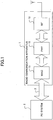
- FIG. 1 shows an example of a configuration of a common radio communication apparatus.
- the radio communication apparatus 1 is connected with a PC system 2 by means of a system bus 3 such as a PCI (Peripheral Component Interface), a USB or such.
- the radio communication apparatus 1 receives data transmitted from an external apparatus via radio communication, and transmits the received data to the PC system 2 by means of the system bus 3.
- the radio communication apparatus 1 may be incorporated in the PC system 2.
- the radio communication apparatus 1 has a MAC (Media Access Control) part 11, a PHY (physical layer) part 12 and a RF (Radio Frequency) part 13.
- MAC Media Access Control
- PHY physical layer
- RF Radio Frequency
- the MAC part 11 acts as a transmission control part for controlling data transmission between the PC system 2 and the external apparatus.
- the PHY part 12 acts as a physical layer defining network physical connection and transmission method.
- the RF part 13 acts as a radio input/output part for carrying out data transmission/reception with the external apparatus by air.
- the radio communication apparatus 1 of FIG. 1 carries out radio communication with the external apparatus by means of wireless USB.
- an interface between the MAC part 11 and the PHY part 12 is compliance with WiMedia MAC-PHY interface specifications.
- WiMedia is a lower layer standard, and is designed in such a manner that various upper layer protocols (WiNet, Wireless1394, Bluetooth (registered trade name) and so forth) can coexist.
- a radio communication apparatus which mounts WiMedia has a CCA_STATUS (Clear Channel Assessment Status) signal indicating a state of a radio wave of the radio communication, in the MAC-PHY interface.
- the CCA_STATUS signal is activated by the PHY part 12 when a signal level of a radio medium signal received by the RF part 13 exceeds a predetermined level.
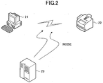
- FIG. 2 shows one example of a wireless system including a PC and a peripheral.
- the PC 21 carries out data transmission with a multi-function peripheral (MFP) 22 by means of radio communication according to the WiMedia standard.
- MFP multi-function peripheral
- Japanese Laid-Open Patent Application No. 11-150756 discloses communication facilities in which collision can be avoided even when the same sub-frequency bands are simultaneously captured between different radio stations.
- the radio facilities include a plurality of radio systems including at least one radio station.
- the radio system transmits a pulse previously controlled in the sub-frequency band before transmitting an effective signal. As a result, it is possible to determine whether or not it has occupied the sub-frequency band different from that of the other radio system.
- Japanese Laid-Open Patent Application 2003-46515 discloses a radio communication apparatus by which radio communication between a radio parent apparatus and a radio child apparatus can be positively carried out as a result of a radio channel having a noise mixed which affects the radio communication being previously- detected.
- This radio communication apparatus carries out carrier sensing in sequence on frequencies which may affect the radio communication other than a carrier frequency of a radio channel to actually apply. Then, when a test frequency exceeding a predetermined value in a carrier sensing level is detected, a channel corresponding to the test frequency is determined as a noise-mixed channel in which the noise is mixed.
- US 2004/0047324 A1 discloses a system for managing communication with a plurality of wireless client devices wherein spectrum profile information describing the radio frequency environment (activity in the frequency band) at a wireless client device is sent to the wireless base station device (where the parameter controls are made) from either a wireless client device or another radio device in the proximity of one or more wireless client devices that is capable of generating the spectrum profile information.
- EP 1 257 090 A1 describes an algorithm for the assignment of channels used by access points (APs) in wireless LANs in a dynamic way in order to achieve the best performance.
- the assignment of channels is based on a procedure in which an AP passively listens on the other channels during idle time.
- the AP calculates the optimal channel with the least interference and sharing.
- the above-mentioned communication facilities of Japanese Laid-Open Patent Application 11- 150756 transmit a pulse-like radio wave for determining whether or not the same sub-frequency band is simultaneously captured between different radio stations. Thereby, a noise may be generated therefrom. Further, in the above-mentioned radio communication apparatus of Japanese Laid-Open Patent Application 2003-46515 , whether or not a channel can be actually used can be determined only from whether or not a carrier is included therein.
- an object of the present invention is to provide a radio communication apparatus by which an influence of a noise can be avoided as a result of the noise of a frequency-band upon communication being quantitatively evaluated.
- a radio communication apparatus is provided, as defined in the appended claims.
- Such a radio communication apparatus in which it is possible to quantitatively evaluate a noise in a frequency band upon communication, and to avoid an influence of the noise.
- a radio communication apparatus includes noise detecting means for detecting a noise of a frequency band upon communication; determining means for determining whether or not the thus-detected noise exceeds a predetermined level; and communication changing means for changing the frequency band and/or a communication radio field intensity based on a determination result of said determining means.
- such a radio communication apparatus in which it is possible to quantitatively evaluate a noise in a frequency band upon communication, and to avoid an influence of the noise.
- a radio communication apparatus by detecting a CCA_STATUS signal and a PHY_ACTIVE (Physical Layer Active Indication) signal provided in the WiMedia MAC-PHY interface specifications together, it is detected whether or not a frequency band upon communication is affected by a noise from another apparatus or such, and, when the frequency band upon communication is affected by the noise from the other apparatus or such, switching is made to another available frequency band which is not affected, or, a communication field intensity is sufficiently increased so that an influence of the noise may not appear. As a result, it is possible to ensure proper communication quality in the radio communication apparatus.
- the radio communication apparatus may further have a measuring time timer for setting a time for the noise detecting means to detect the noise.
- the radio communication apparatus may further has intensity determining means for detecting the level of the noise.
- the radio communication apparatus may further have intensity threshold setting means for setting a threshold for the noise detecting means to detect the noise.
- the threshold may have hysteresis characteristics.
- the radio communication apparatus in the related art mounting WiMedia has the CCA_STATUS signal indicating a signal state of radio communication.
- a method for using this signal is not particularly prescribed, and should be determined by an apparatus designer. Therefore, according to the best mode for carrying out the present invention, the signal is utilized to carry out noise evaluation of a frequency band upon communication.
- FIG. 3 shows a configuration of a MAC part included in a radio communication apparatus according to the best mode for carrying out the present invention.
- the other parts of the radio communication apparatus according to the best mode for carrying out the present invention may be the same as those of the radio communication apparatus 1 mounting WiMedia described above as the related art with reference to FIG. 1 , and descriptions thereof are omitted.
- the MAC part 300 includes a control part 31, a PC interface (IF) 32, a TX (transmission) block 33, a RX (reception) block 34, a transmission/reception data buffer 35 and a noise evaluating part 36.
- the control part 31 controls the respective parts of the MAC part 300, and includes a CPU (Central Processing Unit) and a ROM (Read Only Memory).
- the PC interface 32 acts as an input/output part for carrying out data transmission/reception with the PC system 2.
- the TX block 33 acts as a transmitting part for transmitting data to the PHY part 12.
- the RX block 34 acts as a receiving part for receiving data from the PHY part 12.
- the transmission/reception data buffer 35 acts as a storing part for temporarily storing data which is received from the PC system 2 via the PC interface 32 to be transmitted to the PHY part 12 by means of the TX block 33, as well as data which is received from the PHY part 12 by means of the RX block 34 to be transmitted to the PC system 2 by means of the PC interface 32.
- the noise evaluating part 36 is a part for evaluating a noise in a frequency band currently used in radio communication with an external apparatus.
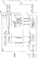
- FIG. 4 shows a first example of a configuration of the MAC part according to the best mode for carrying out the present invention. It is noted that, in FIG. 4 , only part of the MAC part is shown, and, thus, only components for describing operations concerning the best mode for carrying out the present invention are shown.
- the noise evaluating part 36a has a measuring time timer 361, a noise detecting part 362 and a determining part 363.
- the measuring time timer 361 acts as a clock of a counting down type, for measuring a predetermined measuring time.
- the noise detecting part 362 acts as a part for detecting a noise of a frequency band upon communication, recording a time (actually, counting the number of given predetermined clock pulses) during which the CCA_STATUS signal indicating a signal state of radio communication output from the PHY part is active and also the PHY_ACTIVE signal is active during the measuring time, and outputting the recording result as a CCA_VALUE signal indicating a CCA_VALUE value.
- the CCA_STATUS signal is a signal indicating that a signal level (i.e., the level of the radio medium signal) of the frequency band upon communication received by the RF part 13 of the radio communication apparatus 1 is equal to or more than the predetermined level, as mentioned above, and, assuming that the predetermined level corresponds to a level at which a signal used in the radio communication is affected, it can be determined that, when the CCA_STATUS signal is active, some radio wave is generated in such a level that it affects the radio communication in the frequency band used for the radio communication.
- the above-mentioned level at which the radio communication is affected corresponds to a level at which some trouble occurs in the radio communication, and depends on transmission/reception power and a data rate of the radio communication. That is, in a case where the radio communication is carried out with low transmission/reception power, the influence appears even from a noise of low power, while, in a case where the radio communication is carried out with high transmission/reception power, the influence may not much arise from a noise of such a low power.
- a threshold for activating the CCA_STATUS signal is determined with the use of a lookup table with respect to the transmission/reception power and the data rate currently used for the radio communication.
- the CCA_STATUS signal it is not possible to determine whether or not a radio wave appearing is one generated for the purpose of the radio communication of the WiMedia radio communication apparatus of the own station or another station, or, the radio wave appearing is one acting as a noise factor generated from a radio wave source other than these WiMedia radio communication apparatuses, against the WiMedia radio communication apparatuses.
- the above-mentioned PHY_ACTIVE signal provided according to the WiMedia standard is used.
- the PHY_ACTIVE signal is a signal provided from WiMedia-PHY (i.e., the PHY part 12 of FIG.
- WiMedia-MAC i.e., the MAC part 300a of FIG. 4 , corresponding to the MAC part 11 of FIG. 1
- WiMedia-MAC i.e., the MAC part 300a of FIG. 4 , corresponding to the MAC part 11 of FIG. 1
- the PHY_ACTIVE signal is not activated or is deactivated.
- 'deactive' means a state of being deactivated, and, the same manner is applied also hereinafter.
- the above-mentioned CCA_VALUE signal output from the nose detection part 362 as the measurement result of the CCA_STATUS signal and the PHY_ACTIVE signal is a value indicating a rate at which a signal having a level equal to or more than the predetermined level appears during the measuring time, and, is used as a measure to determine whether or not the radio frequency band upon communication is affected by a noise.
- the determining part 363 acts as a part for determining whether or not the frequency band upon communication is affected by a noise from another apparatus or such based on the CCA_VALUE signal output from the noise detecting part 362.
- control part 31a has a notifying part 311 and a communication changing part 312.
- the notifying part 311 acts as a part for notifying of a determination result of the determining means 363 of the noise evaluating means 36a, to the PC system 2.
- the communication changing part 312 acts as a part for outputting a switching instruction to the PHY part 12 by means of communication with a SERIAL_DATA signal for the PHY part 12 to change the frequency band upon communication and/or a communication radio field intensity, according to the determination result of the determining part 363 of the noise evaluating part 36a.
- the control part 31a sets a value 'start_value', as a measuring time for the CCA_STATUS signal in the measuring time timer 361.
- the measuring time may be set to adapt to an expected interference factor when a particular interference factor is expected which may affect the frequency band used for communication. For example, as the expectable particular interference factor for when communication is carried out in a server room or such, since it is expected that the server room is operated regularly, the measuring time is set such that, measurement of 10 seconds is carried out 30 times with an interval of 1 minute each therebetween. In another example, for when a microwave oven may affect communication, since the microwave oven is used continuously for several minutes ordinarily, the measuring time is set such that measurement of one minute is carried out three times with an interval of 5 minutes each therebetween.
- the measuring time is set such that continuous measurement of ten minutes is carried out once.
- past noise evaluation results are previously stored in a storage device (not shown) of the control part 31, and, an attempt is made to set such a measuring time with priority, which corresponds to a value in which noise detection occurred most frequently.
- noise measurement is made during a continuous time, for example, 1 or 2 hours.
- a noise is detected at a high detection rate such as that equal to or more than 95 % as a result of the measurement during the above-mentioned measuring time, it can be determined that a noise source exists which generates a noise constantly in the measured location.
- appropriate hardware is required, and thus, hardware cost may increase.
- a frequency band of a microwave oven is 2.4 GHz band and affects a frequency band used by wireless LAN.
- an apparatus which emits a radio wave such as a microwave oven, an electromagnetic cooking machine or such operates, intermittent uses thereof each during minutes through tens of minutes are expected from its common operation manner.
- the following noise measurement method may be used. That is, immediately after a start of radio communication of the radio communication apparatus, or when it is detected that communication quality degrades after the radio communication is carried out for a while, noise measurement of a continues long time is carried out (for example, for 10 minutes or 30 minutes).
- the noise measurement may be made discretely, i.e., the measurement of ten seconds is repeated with an interval of 1 minute each therebetween, or so. In noise evaluation for 30 minutes in which continuous measurement of ten seconds is repeated with an interval of 1 minute each therebetween as mentioned above, merely measurement resources for 300 minutes are required.
- the radio communication wave may affect communication as a noise.
- the following noise measuring method may be used. That is, noise measurement of a relatively short time (for example, ten seconds, 30 seconds or such) is repeated with an interval (for example, 1 minute) each therebetween. Then, in a case where, from the measurement of the short time each, a noise rate is not zero but not so large (for example, more than 0 % and less than 95 %, or such), it can be presumed that another radio communication apparatus operates.
- beacon frames generating communication basic information with fixed intervals are transmitted, where the frame transmission is carried out several time per second, and transmission/reception frame spans are prescribed in the specifications. There, intervals in which no radio wave transmission is allowed exist, and thus, the noise detection rate should not amount to 100 % during the measuring time.
- a noise pattern detected from the measurement is stored in the storage device in the control part 31a. Then, when noise detection is carried out subsequently, the past noise patterns thus stored in the storage device are read. At this time, the noise patterns should be read in such an order that those which have been detected more are read earlier. As a result, the noise patterns are read in such an order that noise patterns of environments a particular user more frequently use are read earlier. As a result, it is possible to effectively reduce the number of procedures required for the noise detection.
- the control part 31a sets a threshold for the CCA_VALUE value acting as a measure to determine whether or not the frequency band upon communication is affected by a noise, in the determining part 363.
- the threshold of 40 % or 60 % of the above-mentioned value 'start_value' is set. That is, in this case, when the time in which the CCA_STATUS signal is active and also the PHY_ACTIVE signal is deactive exceeds 40 % or 60 % of the measuring time (i.e., the value 'start_value') of the measuring time timer 361, which value corresponds to the CCA_VALUE value, the determining part 363 activates a Channel_Busy signal as will be described later.
- the noise evaluating part 36a After setting each value, the noise evaluating part 36a starts measurement of the CCA_STATUS signal and the PHY_ACTIVE signal output from the PHY part 122.
- the control part 31a activates a timer_start signal input to the measuring time timer 361.
- the measuring time timer 361 After the timer_start signal is activated, the measuring time timer 361 starts the time measurement.
- the measuring time timer 361 activates a signal indicating 'upon measurement' during the time measurement. This signal is input to the noise detecting part 362.
- the noise detecting part 362 counts given predetermined clock pulses during a time in which the CCA_STATUS signal output by the PHY part 12 is active and also the PHY_ACTIVE signal is deactive. That is, a time period in which the detected signal level of the frequency band upon communication of the radio medium signal received by the RF part 13 of the radio communication apparatus 1 is equal to or more than the predetermined level due to an influence of a noise from another apparatus or such is recorded.
- the measuring time timer 361 deactivates the signal indicating "upon measurement".
- the noise detecting part 362 responds thereto, to output the record result of the number of the thus-counted clock pulses during the time in which the CCA_STATUS signal is active and also the PHY_ACTIVE signal is deactive, to the determining part 363 as the CCA_VALUE value.
- the determining part 363 determines whether or not the CCA_VALUE value output from the noise detecting part 362 exceeds the threshold set before the measurement by the control part 31a.
- the determining part 363 determines that the frequency band upon communication is affected by a noise of another apparatus or such, and activates the above-mentioned Channel_Busy signal indicating an occupied situation of the frequency band.
- the measuring time timer 361 activates a timer_end signal for notifying the control part 31a of the end of the measurement.
- the control part 31a checks the state of the Channel_Busy signal.
- the control part 31a uses the notifying part 311 to notify the PC system 2 that the frequency band upon communication is affected by a noise of another apparatus or such.
- the PC system 2 thus receiving the notification from the notifying part 311 of the control part 31a carries out any one(s) of the following operations, depending circumstances of a corresponding application program:
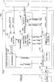
- FIG. 5 shows a second example (embodiment 2) of the configuration of the MAC part in the best mode for carrying out the present invention. It is noted that FIG. 5 shows only part of the MAC part for describing operations of the embodiment 2 according to the best mode for carrying out the present invention.
- the MAC part 300b of FIG. 5 is different from the MAC part 300a of FIG. 4 in that the noise evaluating part 36b further has an intensity determining part 364 for determining the signal level (i.e., signal intensity) upon communication of the radio medium signal received by the RF part 13 of the radio communication apparatus 1. All' the other components have the same functions as those of the MAC part 300a of FIG. 4 and carry out the same operations.
- the intensity determining part 364 has the above-mentioned signal indicating "upon measurement” from the measuring time timer 361 input thereto. During a time in which the signal indicating "upon measurement” is active, the intensity determining part 364 receives a CCA_STRENGTH signal indicating the signal level in the frequency band upon communication of the radio medium signal received by the RF part 13 of the radio communication apparatus 1, and records the same.
- the intensity determining part 364 calculates, from the thus-recorded values of'the CCA_STRENGTH signal, a maximum value CCA_STRENGTH_MAX and an average CCA_STRENGTH_AVE thereof, and outputs the same to the control part 31b. It is noted that, actually, the intensity determining part 364 may record the CCA_STRENGTH signal in predetermined clock timing as a sequence of instantaneous values corresponding to the respective ones of the clock timing during the time of "upon measurement”, sum the thus-recorded values and, therefrom, calculate the maximum value CCA_STRENGTH_MAX and the average CCA_STRENGTH_VE.
- the control part 31b can thus grasp the signal levels in the frequency band upon communication of the radio medium signal received by the RF part 13 of the radio communication apparatus 1, from the values CCA_STRENGTH_MAX and CCA_STRENGTH_AVE thus output from the intensity determining part 364.
- the control part 31b can use the notifying part 311, to notifies the PC system 2 of the information of the signal levels of the radio medium signal received by the RF part 13 of the radio communication apparatus 1 as well as that the frequency band upon communication is affected by a noise from another apparatus or such.
- the PC system 2 thus receiving the notification from the control part 31b, carries out any one(s) of the following operations, depending circumstances of a corresponding application program:
- FIG. 6 shows a third example (embodiment 3) of the configuration of the MAC part according to the best mode for carrying out the present invention. It is noted that FIG. 6 shows only part of the MAC part and thus, only components for describing operations according the embodiment 3 of the best mode for carrying out the present invention.
- the MAC part 300c of FIG. 6 is different from the MAC part 300a in the first example described above in that the noise evaluating part 36c further has an intensity threshold setting part 365 for setting the above-mentioned threshold for activating the CCA_STATUS signal.
- the intensity threshold setting part 365 receives, before a start of the noise measurement by means of the noise detecting part 362, a SET_CCA_THRESH signal indicating the above-mentioned threshold activating the CCA_STATUS signal for the PHY part 12 to activate the CCA_STATUS signal, from the control part 31c, and outputs the value thereof to the PHY part 12 as a CCA_THRESH signal.
- the PHY part 12 activates the CCA_STATUS signal only when the signal level of the radio medium signal of the frequency band upon communication received by the RF part 13 exceeds the value set by the CCA_THRESH signal, and then, outputs the same to the noise evaluating part 36a of the MAC part 300c.
- the control part 31c can recognize a magnitude of a change in the signal level of the radio medium signal received by the RF part 13 of the radio communication apparatus 1 occurring due to an influence of a noise from another apparatus or such in the frequency band upon communication. That is, the control part 31c can determine whether or not the signal level of the radio frequency band upon communication of the radio medium signal received by the RF part 13 of the radio communication apparatus 1 is larger than the threshold for activating the CCA_STATUS signal set in the PHY part 12 by means of the intensity threshold setting part 365, and, when the Channel_Busy signal is activated by the determining part 363, the control part 31c can notify the PC system 2, with the use of the notifying part 311, that the frequency band upon communication is affected by a noise of another apparatus or such, as well as information concerning the signal level of the radio medium signal received by the RF part 13 of the radio communication apparatus 1, when having determining that the signal level of the radio frequency band of the radio medium signal received by the RF part 13 of the radio communication apparatus 1 exceeds the
- the PC system 2 thus receiving the notification from the control part 31c, carries out any one(s) of the following operations, depending circumstances of a corresponding application program:
- the MAC part 300c in the embodiment 3 thus provides the same advantages as those of the MAC part 300b of FIG. 5 using the intensity determining part 364 in the embodiment 2, even with the simpler configuration.
- the control part 31c sets the single threshold for activating the CCA_STATUS signal in the PHY part 12 by means of the intensity threshold setting part 365.
- the intensity threshold setting part 365 may set a plurality of thresholds having different values in the embodiment 4.
- a MAC part 300d of FIG. 7 is different from the MAC part 300c of FIG. 6 described above as the third example, in that a control part 31d sets two different thresholds for activating the CCA_STATUS signal in the PHY part 12 by means of the intensity threshold setting part 365. All the other components have the same functions and carry out the same operations as those of the MAC part 300c of FIG. 6 .
- the intensity threshold setting part 365 receives, from the control part 31c, a SET_CCA_THRESH_ACT signal indicating a first threshold for the PHY part 12 to activate the CCA_STATUS signal and a SET_CCA_THRESH_DEACT signal indicating a second threshold for the PHY part 12 to deactivate the CCA_STATUS signal, and, outputs these values to the PHY part 12 as a CCA THRESH ACT signal and a CCA_THRESH_DEACT signal, respectively.
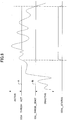
- FIG. 8 shows a diagram, as one example, for illustrating state determination for the CCA_STATUS signal by means of the CCA_THRESH_ACT signal and the CCA_THRESH_DEACT signal.
- the PHY part 12 activates the CCA_STATUS signal when the signal level of the frequency band upon communication of the radio medium signal received by the RF part 13 of the radio communication apparatus 1 exceeds the value (level A) set by the CCA_THRESH_ACT signal. Then, after the CCA_STATUS signal is thus activated, the PHY part 12 deactivates the CCA_STATUS signal when the signal level of the frequency band upon communication of the radio medium signal received by the RF part 13 of the radio communication apparatus 1 lowers from the value (level B ⁇ level A) set by the CCA_THRESH_DEACT signal.
- the state of the CCA_STATUS signal is not changed. That is, the CCA_STATUS signal after being activated is kept in the active state until the signal level of the radio medium signal received by the RF part 13 of the radio communication apparatus 1 lowers from the level B.
- the MAC part 300d in the embodiment 4 can obtain a stable evaluation result even when the signal level of the radio medium signal received by the RF part 13 of the radio communication apparatus 1 changes around the threshold, in comparison to the MAC part 300c of FIG. 6 setting the single threshold for activating the CCA_STATUS signal in the embodiment 3.
- the CCA_STATUS signal is determined whether the CCA_STATUS signal is to be activated or deactivated, by means of a level determining function thus having so-called hysteresis characteristics.
- CCA_THRESH_DEACT CCA_THRESH_ACT ⁇ CCA_THRESH_DELTA
- (CCA_THRESH_DEACT), (CCA_THRESH_ACT) and (CCA_THRESH_DELTA) represent the values indicated by the CCA_THRESH_DEACT signal, the CCA_THRESH_ACT signal and the CCA_THRESH_DELTA signal, respectively.
Landscapes
- Engineering & Computer Science (AREA)
- Computer Networks & Wireless Communication (AREA)
- Signal Processing (AREA)
- Theoretical Computer Science (AREA)
- Physics & Mathematics (AREA)
- General Engineering & Computer Science (AREA)
- General Physics & Mathematics (AREA)
- Mobile Radio Communication Systems (AREA)
- Small-Scale Networks (AREA)
- Transceivers (AREA)
Claims (5)
- Funkkommunikationsvorrichtung, die Folgendes umfasst:Rauschdetektionsmittel (362), um ein Rauschen eines Frequenzbandes bei der Kommunikation zu detektieren, die konfiguriert sind, einen Wert auszugeben, der eine Zeitdauer angibt, in der ein von der Funkkommunikationsvorrichtung empfangener Signalpegel während einer Messzeit gleich oder größer als ein vorgegebener Pegel ist;Bestimmungsmittel (363), die konfiguriert sind, zu bestimmen, ob der von den Rauschdetektionsmitteln ausgegebene Wert einen vorgegebenen Anteil der Messzeit überschreitet; undKommunikationsänderungsmittel (312), um das Frequenzband und/oder die Kommunikations-Funkfeldstärke anhand eines Bestimmungsergebnisses der Bestimmungsmittel zu ändern.
- Funkkommunikationsvorrichtung nach Anspruch 1, die ferner Folgendes umfasst:einen Messzeit-Zeitgeber, um die Messzeit für die Rauschdetektionsmittel (362) zum Detektieren des Rauschens einzustellen.
- Funkkommunikationsvorrichtung nach Anspruch 1 oder 2, die ferner Folgendes umfasst:Stärkebestimmungsmittel (364), um den Rauschpegel zu detektieren.
- Funkkommunikationsvorrichtung nach Anspruch 1 oder 2, die ferner Folgendes umfasst:Stärkeschwellenwert-Einstellmittel (365), um den vorgegebenen Pegel einzustellen.
- Funkkommunikationsvorrichtung nach Anspruch 4, wobei:der vorgegebene Pegel Hystereseeigenschaften besitzt.
Applications Claiming Priority (3)
| Application Number | Priority Date | Filing Date | Title |
|---|---|---|---|
| JP2006073400 | 2006-03-16 | ||
| JP2006299655A JP2007282180A (ja) | 2006-03-16 | 2006-11-02 | 無線通信装置 |
| PCT/JP2007/055329 WO2007105816A1 (en) | 2006-03-16 | 2007-03-12 | Radio communication apparatus |
Publications (3)
| Publication Number | Publication Date |
|---|---|
| EP2005776A1 EP2005776A1 (de) | 2008-12-24 |
| EP2005776A4 EP2005776A4 (de) | 2013-11-06 |
| EP2005776B1 true EP2005776B1 (de) | 2016-05-11 |
Family
ID=38509627
Family Applications (1)
| Application Number | Title | Priority Date | Filing Date |
|---|---|---|---|
| EP07738776.9A Ceased EP2005776B1 (de) | 2006-03-16 | 2007-03-12 | Funkkommunikationsvorrichtung |
Country Status (5)
| Country | Link |
|---|---|
| EP (1) | EP2005776B1 (de) |
| JP (1) | JP2007282180A (de) |
| KR (1) | KR101066950B1 (de) |
| CN (1) | CN101395943B (de) |
| WO (1) | WO2007105816A1 (de) |
Families Citing this family (5)
| Publication number | Priority date | Publication date | Assignee | Title |
|---|---|---|---|---|
| US9729420B2 (en) | 2012-04-26 | 2017-08-08 | Hewlett-Packard Development Company, L.P. | Decreasing USB interference to adjacent wireless device |
| JP5651673B2 (ja) * | 2012-11-30 | 2015-01-14 | 東芝テック株式会社 | 無線通信装置およびそのプログラム |
| JP2015056828A (ja) * | 2013-09-13 | 2015-03-23 | 日本電気株式会社 | 高度交通システムに用いられる車載装置、通信方法及びこれらを用いた高度交通システム |
| KR102360930B1 (ko) * | 2014-12-02 | 2022-02-08 | 에스케이플래닛 주식회사 | 데이터 송신 단말, 데이터 송수신 시스템 및 데이터 송신 방법 |
| JP6557700B2 (ja) * | 2017-04-27 | 2019-08-07 | アンリツインフィビス株式会社 | 金属検出装置 |
Family Cites Families (6)
| Publication number | Priority date | Publication date | Assignee | Title |
|---|---|---|---|---|
| DE19735527C2 (de) | 1997-08-16 | 2003-02-06 | Philips Corp Intellectual Pty | Kommunikationssystem mit mehreren Funksystemen |
| DE60107207T2 (de) * | 2001-05-08 | 2005-12-01 | Lucent Technologies Inc. | Drahtloses lokales Netz mit dynamischer Frequenzwahl |
| JP2003046515A (ja) | 2001-07-31 | 2003-02-14 | Ricoh Co Ltd | 画像形成装置管理システムにおける無線通信装置 |
| JP3896824B2 (ja) * | 2001-11-14 | 2007-03-22 | 松下電工株式会社 | 無線チャンネル設定装置及び方法、並びにプログラム、無線通信装置 |
| DE60336273D1 (de) * | 2002-09-05 | 2011-04-14 | Hitachi Ltd | HF-Leistungsverstärker für drahtloses Kommunikationsgerät |
| US7408907B2 (en) | 2002-09-11 | 2008-08-05 | Cisco Technology, Inc. | System and method for management of a shared frequency band using client-specific management techniques |
-
2006
- 2006-11-02 JP JP2006299655A patent/JP2007282180A/ja active Pending
-
2007
- 2007-03-12 EP EP07738776.9A patent/EP2005776B1/de not_active Ceased
- 2007-03-12 KR KR1020087022472A patent/KR101066950B1/ko not_active Expired - Fee Related
- 2007-03-12 CN CN2007800078714A patent/CN101395943B/zh not_active Expired - Fee Related
- 2007-03-12 WO PCT/JP2007/055329 patent/WO2007105816A1/en not_active Ceased
Also Published As
| Publication number | Publication date |
|---|---|
| CN101395943B (zh) | 2012-09-05 |
| KR20080097463A (ko) | 2008-11-05 |
| WO2007105816A1 (en) | 2007-09-20 |
| KR101066950B1 (ko) | 2011-09-23 |
| CN101395943A (zh) | 2009-03-25 |
| EP2005776A4 (de) | 2013-11-06 |
| JP2007282180A (ja) | 2007-10-25 |
| EP2005776A1 (de) | 2008-12-24 |
Similar Documents
| Publication | Publication Date | Title |
|---|---|---|
| EP3195665B1 (de) | Anpassung von blindempfangsdauer auf reichweite und überlastung | |
| US10419940B2 (en) | Systems and methods of adaptive mitigation for shared access | |
| EP1257090B1 (de) | Drahtloses lokales Netz mit dynamischer Frequenzwahl | |
| US7035275B2 (en) | Non-collaborative mechanisms for enhanced coexistence of wireless networks | |
| US9185747B2 (en) | Wireless communication device | |
| US20170086213A1 (en) | Unlicensed frequency band with licensed frequency band timing | |
| EP2207395A2 (de) | Nutzung von Dauerstörungsinformationen zur Radiosenderauswahl | |
| EP2005776B1 (de) | Funkkommunikationsvorrichtung | |
| EP2695304A2 (de) | Reduzierung des energieverbrauchs in drahtlosen vorrichtungen | |
| US10476775B2 (en) | Systems and methods for LTE-U detection | |
| US9380541B1 (en) | Managing specific absorption rate distribution to maximize transmit power of a wireless device | |
| EP3639575B1 (de) | Technik zur durchführung der kommunikation in einem drahtloskommunikationsnetzwerk | |
| CN112584467B (zh) | 节能信号的发送方法、波束信息的上报方法、设备及终端 | |
| KR20220005532A (ko) | 통신 방법 및 통신 장치 | |
| WO2017133443A1 (zh) | 一种非授权频段上行功率控制方法及相关设备 | |
| US8483629B2 (en) | Determination of coupling between radio devices | |
| WO2018202658A1 (en) | Dynamic adaptivity mode | |
| McHenry | The probe spectrum access method | |
| US20250254529A1 (en) | Coexistence of uwb and wi-fi optimizations | |
| KR101860863B1 (ko) | 기기내 공존 간섭을 고려한 측정보고의 수행장치 및 방법 | |
| US20250254528A1 (en) | Coexistence of uwb and wi-fi optimizations | |
| CN118678480A (zh) | 无线通信方法、装置、电子设备及可读存储介质 | |
| CN118368646A (zh) | 空口并发方法、通信装置及系统 |
Legal Events
| Date | Code | Title | Description |
|---|---|---|---|
| PUAI | Public reference made under article 153(3) epc to a published international application that has entered the european phase |
Free format text: ORIGINAL CODE: 0009012 |
|
| 17P | Request for examination filed |
Effective date: 20080821 |
|
| AK | Designated contracting states |
Kind code of ref document: A1 Designated state(s): DE FR GB |
|
| RBV | Designated contracting states (corrected) |
Designated state(s): DE FR GB |
|
| DAX | Request for extension of the european patent (deleted) | ||
| A4 | Supplementary search report drawn up and despatched |
Effective date: 20131004 |
|
| RIC1 | Information provided on ipc code assigned before grant |
Ipc: H04W 24/10 20090101ALN20130927BHEP Ipc: H04W 28/04 20090101AFI20130927BHEP Ipc: H04B 1/10 20060101ALI20130927BHEP Ipc: H04W 36/06 20090101ALN20130927BHEP |
|
| REG | Reference to a national code |
Ref country code: DE Ref legal event code: R079 Ref document number: 602007046265 Country of ref document: DE Free format text: PREVIOUS MAIN CLASS: H04Q0007360000 Ipc: H04W0028040000 |
|
| GRAP | Despatch of communication of intention to grant a patent |
Free format text: ORIGINAL CODE: EPIDOSNIGR1 |
|
| RIC1 | Information provided on ipc code assigned before grant |
Ipc: H04W 28/04 20090101AFI20151028BHEP Ipc: H04B 1/10 20060101ALI20151028BHEP Ipc: H04W 36/06 20090101ALN20151028BHEP Ipc: H04W 24/10 20090101ALN20151028BHEP |
|
| INTG | Intention to grant announced |
Effective date: 20151118 |
|
| RIN1 | Information on inventor provided before grant (corrected) |
Inventor name: SATOH, TETSUYA |
|
| GRAS | Grant fee paid |
Free format text: ORIGINAL CODE: EPIDOSNIGR3 |
|
| GRAA | (expected) grant |
Free format text: ORIGINAL CODE: 0009210 |
|
| AK | Designated contracting states |
Kind code of ref document: B1 Designated state(s): DE FR GB |
|
| REG | Reference to a national code |
Ref country code: GB Ref legal event code: FG4D |
|
| REG | Reference to a national code |
Ref country code: DE Ref legal event code: R096 Ref document number: 602007046265 Country of ref document: DE |
|
| REG | Reference to a national code |
Ref country code: DE Ref legal event code: R097 Ref document number: 602007046265 Country of ref document: DE |
|
| PLBE | No opposition filed within time limit |
Free format text: ORIGINAL CODE: 0009261 |
|
| STAA | Information on the status of an ep patent application or granted ep patent |
Free format text: STATUS: NO OPPOSITION FILED WITHIN TIME LIMIT |
|
| REG | Reference to a national code |
Ref country code: FR Ref legal event code: PLFP Year of fee payment: 11 |
|
| 26N | No opposition filed |
Effective date: 20170214 |
|
| REG | Reference to a national code |
Ref country code: FR Ref legal event code: PLFP Year of fee payment: 12 |
|
| PGFP | Annual fee paid to national office [announced via postgrant information from national office to epo] |
Ref country code: GB Payment date: 20180321 Year of fee payment: 12 Ref country code: DE Payment date: 20180322 Year of fee payment: 12 |
|
| PGFP | Annual fee paid to national office [announced via postgrant information from national office to epo] |
Ref country code: FR Payment date: 20180330 Year of fee payment: 12 |
|
| REG | Reference to a national code |
Ref country code: DE Ref legal event code: R119 Ref document number: 602007046265 Country of ref document: DE |
|
| GBPC | Gb: european patent ceased through non-payment of renewal fee |
Effective date: 20190312 |
|
| PG25 | Lapsed in a contracting state [announced via postgrant information from national office to epo] |
Ref country code: DE Free format text: LAPSE BECAUSE OF NON-PAYMENT OF DUE FEES Effective date: 20191001 Ref country code: GB Free format text: LAPSE BECAUSE OF NON-PAYMENT OF DUE FEES Effective date: 20190312 |
|
| PG25 | Lapsed in a contracting state [announced via postgrant information from national office to epo] |
Ref country code: FR Free format text: LAPSE BECAUSE OF NON-PAYMENT OF DUE FEES Effective date: 20190331 |