EP2005486B1 - Electrical connecting device for flat conductors - Google Patents
Electrical connecting device for flat conductors Download PDFInfo
- Publication number
- EP2005486B1 EP2005486B1 EP07727777A EP07727777A EP2005486B1 EP 2005486 B1 EP2005486 B1 EP 2005486B1 EP 07727777 A EP07727777 A EP 07727777A EP 07727777 A EP07727777 A EP 07727777A EP 2005486 B1 EP2005486 B1 EP 2005486B1
- Authority
- EP
- European Patent Office
- Prior art keywords
- connecting device
- housing
- mounting
- webs
- flat conductor
- Prior art date
- Legal status (The legal status is an assumption and is not a legal conclusion. Google has not performed a legal analysis and makes no representation as to the accuracy of the status listed.)
- Not-in-force
Links
- 239000004020 conductor Substances 0.000 title claims abstract description 63
- 238000005192 partition Methods 0.000 claims description 6
- 230000004308 accommodation Effects 0.000 claims 2
- 230000001681 protective effect Effects 0.000 abstract 1
- 238000009434 installation Methods 0.000 description 8
- 238000005516 engineering process Methods 0.000 description 4
- 239000002390 adhesive tape Substances 0.000 description 2
- 210000004907 gland Anatomy 0.000 description 2
- 229910000881 Cu alloy Inorganic materials 0.000 description 1
- 238000005452 bending Methods 0.000 description 1
- 230000008878 coupling Effects 0.000 description 1
- 238000010168 coupling process Methods 0.000 description 1
- 238000005859 coupling reaction Methods 0.000 description 1
- 230000007547 defect Effects 0.000 description 1
- 230000001419 dependent effect Effects 0.000 description 1
- 230000005611 electricity Effects 0.000 description 1
- 239000002360 explosive Substances 0.000 description 1
- 238000003780 insertion Methods 0.000 description 1
- 230000037431 insertion Effects 0.000 description 1
- 230000003993 interaction Effects 0.000 description 1
- 239000000463 material Substances 0.000 description 1
- 239000012528 membrane Substances 0.000 description 1
- 239000002184 metal Substances 0.000 description 1
- 238000000034 method Methods 0.000 description 1
- 230000002093 peripheral effect Effects 0.000 description 1
- 150000003071 polychlorinated biphenyls Chemical class 0.000 description 1
- 230000000284 resting effect Effects 0.000 description 1
- 238000000926 separation method Methods 0.000 description 1
- 230000006641 stabilisation Effects 0.000 description 1
- 238000011105 stabilization Methods 0.000 description 1
- 230000000087 stabilizing effect Effects 0.000 description 1
Images


Classifications
-
- H—ELECTRICITY
- H01—ELECTRIC ELEMENTS
- H01R—ELECTRICALLY-CONDUCTIVE CONNECTIONS; STRUCTURAL ASSOCIATIONS OF A PLURALITY OF MUTUALLY-INSULATED ELECTRICAL CONNECTING ELEMENTS; COUPLING DEVICES; CURRENT COLLECTORS
- H01R9/00—Structural associations of a plurality of mutually-insulated electrical connecting elements, e.g. terminal strips or terminal blocks; Terminals or binding posts mounted upon a base or in a case; Bases therefor
- H01R9/22—Bases, e.g. strip, block, panel
-
- H—ELECTRICITY
- H01—ELECTRIC ELEMENTS
- H01L—SEMICONDUCTOR DEVICES NOT COVERED BY CLASS H10
- H01L31/00—Semiconductor devices sensitive to infrared radiation, light, electromagnetic radiation of shorter wavelength or corpuscular radiation and specially adapted either for the conversion of the energy of such radiation into electrical energy or for the control of electrical energy by such radiation; Processes or apparatus specially adapted for the manufacture or treatment thereof or of parts thereof; Details thereof
- H01L31/02—Details
- H01L31/02002—Arrangements for conducting electric current to or from the device in operations
- H01L31/02005—Arrangements for conducting electric current to or from the device in operations for device characterised by at least one potential jump barrier or surface barrier
- H01L31/02008—Arrangements for conducting electric current to or from the device in operations for device characterised by at least one potential jump barrier or surface barrier for solar cells or solar cell modules
- H01L31/02013—Arrangements for conducting electric current to or from the device in operations for device characterised by at least one potential jump barrier or surface barrier for solar cells or solar cell modules comprising output lead wires elements
-
- H—ELECTRICITY
- H02—GENERATION; CONVERSION OR DISTRIBUTION OF ELECTRIC POWER
- H02S—GENERATION OF ELECTRIC POWER BY CONVERSION OF INFRARED RADIATION, VISIBLE LIGHT OR ULTRAVIOLET LIGHT, e.g. USING PHOTOVOLTAIC [PV] MODULES
- H02S40/00—Components or accessories in combination with PV modules, not provided for in groups H02S10/00 - H02S30/00
- H02S40/30—Electrical components
- H02S40/34—Electrical components comprising specially adapted electrical connection means to be structurally associated with the PV module, e.g. junction boxes
-
- H—ELECTRICITY
- H01—ELECTRIC ELEMENTS
- H01R—ELECTRICALLY-CONDUCTIVE CONNECTIONS; STRUCTURAL ASSOCIATIONS OF A PLURALITY OF MUTUALLY-INSULATED ELECTRICAL CONNECTING ELEMENTS; COUPLING DEVICES; CURRENT COLLECTORS
- H01R4/00—Electrically-conductive connections between two or more conductive members in direct contact, i.e. touching one another; Means for effecting or maintaining such contact; Electrically-conductive connections having two or more spaced connecting locations for conductors and using contact members penetrating insulation
- H01R4/28—Clamped connections, spring connections
- H01R4/48—Clamped connections, spring connections utilising a spring, clip, or other resilient member
- H01R4/4809—Clamped connections, spring connections utilising a spring, clip, or other resilient member using a leaf spring to bias the conductor toward the busbar
-
- Y—GENERAL TAGGING OF NEW TECHNOLOGICAL DEVELOPMENTS; GENERAL TAGGING OF CROSS-SECTIONAL TECHNOLOGIES SPANNING OVER SEVERAL SECTIONS OF THE IPC; TECHNICAL SUBJECTS COVERED BY FORMER USPC CROSS-REFERENCE ART COLLECTIONS [XRACs] AND DIGESTS
- Y02—TECHNOLOGIES OR APPLICATIONS FOR MITIGATION OR ADAPTATION AGAINST CLIMATE CHANGE
- Y02E—REDUCTION OF GREENHOUSE GAS [GHG] EMISSIONS, RELATED TO ENERGY GENERATION, TRANSMISSION OR DISTRIBUTION
- Y02E10/00—Energy generation through renewable energy sources
- Y02E10/50—Photovoltaic [PV] energy
Landscapes
- Engineering & Computer Science (AREA)
- Computer Hardware Design (AREA)
- Microelectronics & Electronic Packaging (AREA)
- Sustainable Energy (AREA)
- Physics & Mathematics (AREA)
- Condensed Matter Physics & Semiconductors (AREA)
- Electromagnetism (AREA)
- Sustainable Development (AREA)
- Life Sciences & Earth Sciences (AREA)
- General Physics & Mathematics (AREA)
- Power Engineering (AREA)
- Photovoltaic Devices (AREA)
- Multi-Conductor Connections (AREA)
- Optical Couplings Of Light Guides (AREA)
- Coupling Device And Connection With Printed Circuit (AREA)
- Compositions Of Macromolecular Compounds (AREA)
Abstract
Description
Die Erfindung betrifft eine Anschlußvorrichtung für Leiterenden, insbesondere Messerkontakte, an Photovoltaikanlagen nach dem Oberbegriff des Anspruchs 1.The invention relates to a connection device for conductor ends, in particular blade contacts, to photovoltaic systems according to the preamble of
Photovoltaikanlagen weisen in der Regel wenigstens ein Photovoltaikpaneel zur Stromerzeugung aus Sonnenlicht auf. Dabei sind in der Regel flexible Flachleiter aus den Photovoltaikpaneelen herausgeführt, die es ermöglichen, die Photovoltaikpaneele - in der Regel über ein Mehrleiterkabel - beispielsweise an eine Hausinstallation oder zunächst an elektrische Geräte wie einen Wechselrichter oder dgl. anzuschließen.Photovoltaic systems usually have at least one photovoltaic panel for generating electricity from sunlight. In this case, flexible flat conductors are usually led out of the photovoltaic panels, which make it possible to connect the photovoltaic panels-as a rule via a multi-conductor cable-for example to a domestic installation or firstly to electrical appliances such as an inverter or the like.
Dabei ist es der Stand der Technik, die einzelnen Flachleiter mittels Einzelklemmen oder dgl. von Hand zu kontaktieren. Aus diesem Grund ist der Anschluss der Geräte relativ mühsam und es ist in der Regel notwendig, zum Anschluss der Geräte besonders geschulte Fachkräfte einzusetzen.It is the prior art, the individual flat conductor by means of individual terminals or the like. To contact by hand. For this reason, the connection of the devices is relatively cumbersome and it is usually necessary to use specially trained professionals for connecting the devices.
Ergänzend besteht das Problem, dass die derart erstellten Installationen in der Regel relativ unübersichtlich sind und von daher im Störungsfall auch nur schwer instand zu setzen sind.In addition, there is the problem that the installations created in this way are usually relatively confusing and are therefore difficult to repair in the event of a fault.
Es sind auch gattungsgemäße Anschlussvorrichtungen mit einem Aufnahmegehäuse für die Flachleiterenden bekannt, mit welchen die Leiterenden kontaktiert werden (
Vor diesem Hintergrund ist es die Aufgabe der Erfindung, eine Anschlußvorrichtung bzw. eine Anschlusseinrichtung für Flachleiter zu realisieren, mit der auf einfachere Weise als nach dem Stand der Technik eine Kontaktierung der Flachleiter und deren . Anschluss an ein übergeordnetes Gerät oder System realisierbar ist.Against this background, it is the object of the invention to realize a connection device or a connection device for flat conductors, with the simpler way than in the prior art, a contacting of the leads and their. Connection to a higher-level device or system is feasible.
Die Erfindung löst diese Aufgabe durch den Gegenstand des Anspruchs 1.The invention solves this problem by the subject matter of
Vorteilhafte Ausgestaltungen sind den Unteransprüchen zu entnehmen.Advantageous embodiments can be found in the dependent claims.
Sie schafft auch den Gegenstand des Anspruchs 30.It also provides the subject matter of
Anspruch 1 beschreibt eine Anschlussvorrichtung für Leiterenden, insbesondere Flachleiterenden an einem Photovoltaikpaneel, aus dem eine Mehrzahl der Flachleiterenden vorsteht, und die ein Aufnahme- bzw. Anschlussgehäuse aufweist, gekennzeichnet durch eine auf dem Photovoltaikpaneel anbringbare, insbesondere aufklebbare Aufnahmeeinheit zur Aufnahme der Flachleiterenden, auf welche das Aufnahmegehäuse aufsetzbar ist.
Derart werden die Flachleiterenden nach Art eines ersten Montageschrittes bzw. einer Vormontage an der Aufnahmeeinheit festgelegt, die dann leichter als vormontierte Einheit kontaktierbar ist als die bekannten Lösungen nach dem Stand der Technik.Thus, the flat conductor ends are determined in the manner of a first assembly step or a pre-assembly of the receiving unit, which is then easier to contact as a preassembled unit than the known solutions according to the prior art.
Vorzugsweise ist die Aufnahmeeinheit als Aufnahmeträger ausgebildet, der wenigstens eine Aufnahme oder eine Mehrzahl von Aufnahmen, insbesondere Aufnahmestegen aufweist, über die jeweils eines der Flachleiterenden biegbar ist.Preferably, the receiving unit is designed as a recording medium, which has at least one receptacle or a plurality of receptacles, in particular receiving webs, via which in each case one of the flat conductor ends is bendable.
Dabei ist es zweckmäßig, wenn das Aufnahmegehäuse auf den Aufnahmeträger aufsteckbar, z.B. aufrastbar istIt is expedient if the receiving housing attachable to the recording medium, e.g. is latched
Vorzugsweise weist die Aufnahmeeinheit Aufnahmen, insbesondere Aufnahmestege, auf, über die oder an denen jeweils eines der Flachleiterenden biegbar festlegbar ist.The receiving unit preferably has receptacles, in particular receiving webs, over which or on each of which one of the flat conductor ends can be fixed in a bendable manner.
Besonders bevorzugt und vorteilhaft geschieht dieses Festlegen an den Aufnahmestege, so dass aus der übergeordneten Einheit aus den Flachleiterenden auf den Aufnahmestegen und dem Aufnahmeträger quasi eine Art Stecker als Teil der Anschlussvorrichtung bzw. der Anschlusseinrichtung direkt am Photovoltaikpaneel ausgebildet wird.Particularly preferred and advantageous this setting is done on the receiving webs, so that from the parent unit from the flat conductor ends on the receiving webs and the recording medium quasi a kind of plug as part of the connecting device and the connecting device is formed directly on the photovoltaic panel.
Die Aufnahmestege können aus Kunststoff oder einem anderen, ggf. auch leitenden Material bestehen, sofern zwischen den Flachleiterenden eine ggf. erforderliche galvanische Trennung realisiert ist. Im Bereich jedes Aufnahmesteges werden damit aus den Flachleiterenden über den Aufnahmestegen stabile Kontakte, die ohne weiteres auch gegen größere Kräfte z.B. in einen Federkontakt (insbesondere auch in Push-In-Technik) einschiebbar sind.The receiving webs may be made of plastic or another, possibly also conductive material, if between the flat conductor ends a possibly required galvanic Separation is realized. In the area of each receiving web are thus from the flat conductor ends on the receiving webs stable contacts that are readily insertable against larger forces, for example in a spring contact (especially in push-in technology).
Es ist vorteilhaft, über diese vormontierbare Einheit das Aufnahmegehäuse als weiteren teil der Anschlussvorrichtung zu setzen, das vorzugsweise eine abschnittsweise offene Bodenseite aufweist, so dass es über den Aufnahmeträger setzbar ist. Dieses Gehäuse bildet vorzugsweise ebenfalls einen Teil der bereits vor der Montage auf dem Dach vormontierbaren Einheit, so dass auf dem Dach nur noch das Photovoltaikpaneel mit der Box als Ganzes vorkonfektioniert und vormontiert beispielsweise an einen Wechselrichter anzuschließen ist.It is advantageous to set the receiving housing as a further part of the connecting device via this preassemblable unit, which preferably has a partially open bottom side, so that it can be placed over the receiving carrier. This housing also preferably forms part of the unit that can be preassembled on the roof prior to assembly, so that only the photovoltaic panel with the box as a whole can be prefabricated and preassembled, for example, to an inverter on the roof.
Mit der Erfindung wird der Anschluss von Photovoltaikpanelen an übergeordnete Installationssysteme deutlich vereinfacht. Der Anschluss kann schneller und nach einer besonders bevorzugten Variante sogar werkzeuglos geschehen. Der Zeitaufwand wird wie die Gefahr der Fehlinstallation deutlich verringert. Zudem wird durch die übersichtliche und quasi selbsterklärende Installation auch eine leichtere Wartung und Instandhaltung der Anlage ermöglicht.The invention considerably simplifies the connection of photovoltaic panels to higher-level installation systems. The connection can be done faster and after a particularly preferred variant even without tools. The time required is reduced significantly, as is the risk of incorrect installation. In addition, the clear and almost self-explanatory installation also makes it easier to maintain and maintain the system.
Die Aufnahmestege können miteinander fluchten oder versetzt zueinander.angeordnet sein. Es ist auch denkbar, sie sämtlichst parallel zueinander insbesondere in einer einzigen Reihe anzuordnen, da derart eine besonders schmale, aber dafür etwas längere Anschlussvorrichtung realisierbar ist.The receiving webs can be aligned with one another or offset from one another. It is also conceivable to arrange them all parallel to one another, in particular in a single row, since in this way a particularly narrow but for a somewhat longer connection device can be realized.
Die Erfindung schafft auch eine Anschlussvorrichtung für Leiterenden, insbesondere Flachleiterenden an einem Photovoltaikpaneel, aus dem eine Mehrzahl der Flachleiterenden vorsteht, und die ein Aufnahme- bzw. Anschlussgehäuse aufweist, welches auf dem Photovoltaikpaneel anbringbar ist, insbesondere Anschlussvorrichtung nach einem der vorstehenden Ansprüche, wobei das Aufnahmegehäuse eine Wanne aufweist, die bis auf Öffnungen für Kabeldurchführungen für Kabel und bis auf die zum Photovoltaikpaneel weisende Seite geschlossen ausgebildet ist.The invention also provides a connecting device for conductor ends, in particular flat conductor ends on a photovoltaic panel from which protrudes a plurality of flat conductor ends, and which has a receiving housing which can be attached to the photovoltaic panel, in particular connecting device according to one of the preceding claims, wherein the Receiving housing has a trough, which is closed except for openings for cable bushings for cables and up to the photovoltaic panel facing side.
Nachfolgend wird die Erfindung unter Bezug auf die Zeichnung anhand eines Ausführungsbeispiels näher beschrieben. Es zeigt:
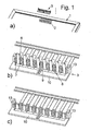
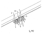
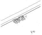
- Fig. 1 a-c
- perspektivische Ansichten eines Randbereiches eines Photovoltaikpa- neels und die Montage eines Montagerahmens an Flachleitern in drei aufeinander folgenden Schritten;
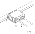
- Fig. 2a,b
- jeweils eine perspektivische Ansicht des Aufnahmegehäuses und die Montage des Aufnahme- bzw. Anschlussgehäuses an dem Montagerah- men in zwei Schritten sowie Ausschnittsvergrößerungen dieser Abbil- dungen;
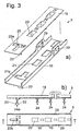
- Fig. 3a, b
- Komponenten einer Anschlussschiene; und
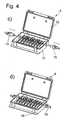
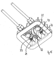
- Fig. 4a-d
- die Montage eines Anschlussgehäuses in vier Schritten;
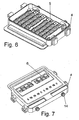
- Fig. 5 - 9
- verschiedene Ansichten eines weiteren Anschlussgehäuses;
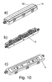
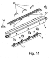
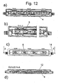
- Fig. 10 - 12
- verschiedene Ansichten eines besonders schmal bauenden weiteren An- schlussgehäuses;
- Fig. 13a - e
- die Montage einer weiteren Anschlussvorrichtung in fünf Schritten;
- Fig. 14 - 15
- verschiedene Ansichten der Anschlussvorrichtung aus
Fig. 13 ; - Fig. 16 - 17
- Schnittansichten zur Montage der Anschlussvorrichtung aus
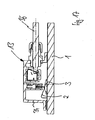
Fig. 13 ; - Fig. 18
- eine Schnittansicht einer weiteren Anschlussvorrichtung im installierten Zustand;
- Fig. 19
- eine Sprengansicht einer weiteren Anschlussvorrichtung;
- Fig. 20
- eine Sprengansichten einer weiteren Anschlussvorrichtung; und
- Fig. 21
- eine Leiterplatte für das Aufnahmegehäuse aus
Fig. 20 .
- Fig. 1 ac
- perspective views of a peripheral region of a photovoltaic panel and the mounting of a mounting frame on flat conductors in three successive steps;
- Fig. 2a, b
- in each case a perspective view of the receiving housing and the mounting of the receiving or connecting housing on the mounting frame in two steps and enlarged detail of these illustrations;
- Fig. 3a, b
- Components of a connecting rail; and
- Fig. 4a-d
- the assembly of a connection housing in four steps;
- Fig. 5-9
- different views of another connection housing;
- Fig. 10 - 12
- different views of a particularly narrow-building further connection housing;
- Fig. 13a - e
- the installation of another connection device in five steps;
- FIGS. 14-15
- different views of the connection device
Fig. 13 ; - Fig. 16 - 17
- Sectional views for mounting the connection device
Fig. 13 ; - Fig. 18
- a sectional view of another connecting device in the installed state;
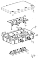
- Fig. 19
- an explosive view of another connection device;
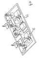
- Fig. 20
- a sprinkler views of another connection device; and
- Fig. 21
- a circuit board for the receiving housing
Fig. 20 ,
Diese Flachleiterenden 2 sind mit einer Anschlussvorrichtung zu kontaktieren. Dies geschieht an einem bzw. mittels einem Aufnahmeträger 3 für die Leiterenden 2. Dieser wird vorzugsweise einfach und schnell mittels eines Doppelklebebandes an der Rückseite des Photovoltaikpaneels befestigt.These flat conductor ends 2 are to be contacted with a connection device. This is done on or by means of a
Der Aufnahmeträger 3 weist eine Reihe von Aufnahmestegen 6 auf, die im montierten Zustand vorzugsweise senkrecht zur Oberfläche des Photovoltaikpaneels ausgerichtet sind und über die jeweils eines der Flachleiterenden 2 biegbar ist, um an den Aufnahmestegen 6 stabile Kontaktbereiche auszubilden.The
Die Aufnahmestege 6 sind hier jeweils beidseits von Trennwänden 7 begrenzt, die senkrecht zu den Aufnahmestegen 6 ausgerichtet sind, so dass die Aufnahmestege 6 für die einzelnen Flachleiterenden 2 klar voneinander getrennt sind, was es ermöglicht, Fehlbeschaltungen zu vermeiden.The receiving
Die Aufnahmestege 6 können aus Kunststoff oder einem anderen Material, ggf. auch Metall, bestehen. Sie können theoretisch nahezu beliebig relativ zueinander ausgerichtet sein, so in einer oder mehreren Reihen nebeneinander oder parallel zueinander oder beispielsweise auch derart, dass sie gemeinsam auf einem Bogen liegen.The receiving
Zunächst werden die Flachleiterenden durch einen Schlitz 8 bzw. eine lang gestreckte Ausnehmung des Aufnahmeträgers 3 gesteckt (
Der Schlitz 8 ist durch einen Stabilisierungssteg 9 in zwei Abschnitte unterteilt.The
Seitlich der jeweils äußersten Trennwände 7 sind hier größere Vorzentrierungsstege 13 ausgebildet, die eine Vorzentrierung und Führung des Aufnahmegehäuses beim Aufsetzen auf den Aufnahmeträger gewährleisten und die damit auch als Fehlsteckschutz dienen.Laterally of each
Ein optionaler Längssteg 10 gegenüber den Aufnahmestegen 6 kann zum Halten genutzt werden und erleichtert die Handhabung.An optional
Auf den Aufnahmeträger 3 ist ein Anschluss- bzw. Aufnahmegehäuse 4 mit einer Mehrzahl von Federklemmleisten 5 - hier in vorteilhafter als Stromschienen mit Anschlusskontakten in Direktstecktechnik (Push-In) ausgebildet - aufsetzbar, insbesondere aufsteckbar.On the
Das Aufnahmegehäuse 4 ist - siehe auch
Im Inneren weist das Aufnahmegehäuse 4 Aufnahmekammern 27 auf, in die welche die Federklemmleisten 5 eingesetzt sind, die als Anschlussschienen(anordnungen) 17 ausgebildet sind. An der Bodenseite 16, mit der das Aufnahmegehäuse 4 beispielsweise auf einen seitlichen Randbereich, z.B. einen Rahmen, eines Photovoltaikpaneels aufsetzbar ist (hier nicht dargestellt), weist jede Aufnahmekammer 27 wenigstens eine Aussparung 28 auf. Die Anschlussschienen(anordnungen) 17 umfassen jeweils eine im Querschnitt u-förmigen Grundschiene 18 und eine in diese eingesetzte Deckschiene 19 (siehe hierzu
Die Grundschiene 18 und die Deckschiene 19 weisen jeweils im montierten Zustand weitgehend fluchtende fensterartige Durchbrüche 20, 21 auf, aus denen Stege 22, 23 derart ausgebogen sind, dass die Stege 22, 23 der Grundschiene 18 und der Deckschiene 19 im montierten Zustand in ihrem Zusammenspiel jeweils tulpenartig geöffnete Federkontakte 24 ausbilden. An jeder Anschlussschiene 17 ist derart eine Mehrzahl der Federkontakte 24 ausgebildet.The
Vorzugsweise besteht die eine der Stromschienen und damit der eine der Steg 22 aus einem Federblech, während die weitere Stromschiene und damit der weitere Steg 23 die Stromschienenfunktion übernimmt und insbesondere aus einer Cu-Legierung besteht. Die Federkontakte 24 bilden derart ein Push-In-Element aus. Jede Anschlussschiene 24 weist noch seitliche weitere Anschlusskontakte 29 auf, die beliebig nutzbar sind, so zur Kontaktierung einer Leitung.Preferably, the one of the busbars and thus the one of the
An kleineren Haltestegen 25 hintergreift die Deckschiene 19 die Grundschiene 18 und ist an dieser gesichert.At
Im Aufnahmegehäuse ist eine Mehrzahl von als Anschlussschienen 17 ausgebildeten Federklemmleisten 5 eingesetzt, wobei die Anzahl der Anschlussschienen 17 vorzugsweise der Anzahl der zu kontaktierenden Flachleiterenden 2 entspricht. Nach
Jeweils einer der Durchbrüche 20a, 21 a ist der Kontur des Aufnahmeträgers 3 angepasst, so dass die Aufnahmestege 6 mit den aufgebogenen Flachleiterenden 2 und die Trennwände 7 jeweils in diese Durchbrüche 20a, 21a der nebeneinander angeordneten Anschlussschienen 17 einschiebbar sind, wobei jeweils einer der Federkontakte 24a eines der Flachleiterenden 2 auf den Aufnahmestegen 6 kontaktiert. Die weiteren Federkontakte 24 sind zum Anschluss von Bauelementen wie Dioden 26 nutzbar (
Dabei kann - je nach Ausgestaltung und Wunsch - auch eine mechanische Verrastung des gesamten Aufnahineträgers 3 erfolgen (hier nicht dargestellt).In this case - depending on the design and desire - also a mechanical locking of the
Mit dem erfindungsgemäßen Aufnahme- bzw. Anschlussgehäuse 4, welches im vormontierten Zustand (
Zur eigentlichen Vormontage der Anschlussbox am Photovoltaikpaneel an sich ist zunächst notwendig, die Flachleiterenden 2 auf die Aufnahmestege 6 des Aufnahmeträgers 3 zu biegen (von Hand oder z.B. mit einer Zange) und dann das ansonsten vormontierte Aufnahmegehäuse 4 aufzusetzen. Sodann kann das Anschlussgehäuse 4 mittels Steckvorrichtungen 15 mit einer übergeordneten Schaltung verbunden werden. Ein direktes Einstecken der Flachleiterenden in das Anschlussgehäuse bzw. die dort vorgesehenen Federkontakte ist aufgrund der großen Federkräfte nicht möglich und erscheint von daher nicht sinnvoll.For the actual preassembly of the connection box on the photovoltaic panel itself, it is first necessary to bend the flat conductor ends 2 onto the receiving
An der Bodenseite 16 des Anschluss- und Aufnahmegehäuses 4 kann eine Dichtung vorgesehen sein, welche den gesamten Kontaktbereich zum Photovoltaikpaneel hin abdichtet (hier nicht dargestellt). Das gesamte Anschlussgehäuse 4 kann mit dem Photovoltaikpaneel z.B. schraubend oder auch klemmend verbunden werden.On the
Die Durchführungen 14 können beliebig an den übrigen Seiten verteilt sein. Optional ist an einer Öffnung eine atmungsaktive Membran zur Ableitung von Feuchtigkeit aus dem Anschlussgehäuse bzw. der Anschlussbox realisierbar (hier nicht dargestellt).The
Nach
An den Enden der Federklemmleistenreihen können hier Anschlusskontakte 30, z.B. in Push-In-Technik vorgesehen sein, welche den Anschluss von anzuschließenden Leitern erlauben. Die Durchführungen 14 sind zur Realisierung einer besonders kompakten Bauform vorzugsweise an den Schmalseiten des lang gestreckten Anschlussgehäuses 4 angeordnet.At the ends of the spring terminal rows,
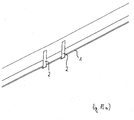
Aus dem Photovoltaikpaneel 1 steht wiederum eine Mehrzahl -also mindestens zwei - Flachleiterenden 2 vor, die parallel zueinander in einer Reihe ausgerichtet sind und deren Endabschnitte vom Photovoltaikpaneel 1 senkrecht nach oben umgebogen sind (
Diese Flachleiterenden 2 sind zu kontaktieren.These flat conductor ends 2 are to be contacted.
Zunächst wird der Aufnahmeträger 2 der Anschlussvorrichtung wiederum vorzugsweise mittels eines Doppelklebebandes an der Rückseite des Photovoltaikpaneels befestigt.First of all, the receiving
Der Aufnahmeträger 3 weist wenigstens einen Aufnahmesteg 3 oder mehrere Aufnahmestege 3 auf. Hier weist er zwei Aufnahmestege 6 auf, die im montierten Zustand vorzugsweise senkrecht zur Oberfläche des Photovoltaikpaneels ausgerichtet sind und über den/die jeweils eines der Flachleiterenden 2 biegbar ist, um an den Aufnahmestegen 6 stabile Kontaktbereiche auszubilden (
Zwischen den Aufnahmestegen 6 ist ein profilierter Zentrierdorn 31 angeordnet, der sich senkrecht vom Aufnahmeträger 3 vorsteht und zum Eingriff in eine entsprechend profilierte Aufnahme 32 am Aufnahmegehäuse ausgelegt ist (siehe auch
Die Aufnahmestege 6 sind hier wiederum beidseits von Trennwänden 7 begrenzt, die senkrecht zu den Aufnahmestegen 6 ausgerichtet sind, so dass die Aufnahmestege 6 für die einzelnen Flachleiterenden 2 klar voneinander getrennt sind, was es ermöglicht, Fehlbeschaltungen zu vermeiden.The receiving
Die Flachleiterenden 2 werden hier von der Seite her über die zugeordneten Aufnahmestege 6 gebogen (
Der Aufnahmeträger 3 bildet einen vormontierten Teil der Anschlussvorrichtung bzw. der Komponenten, welche das Aufnahmegehäuse 4 im montierten Zustand aufnimmt.The receiving
Das Aufnahmegehäuse 4 ist mit Federkontakten 24 versehen, die vorzugsweise von einem Kragen 33 eingefasst sind und die aufgrund des 3 Aufnahmeträgers der zum Einführen der umgebogenen und derart vormontierten Flachleiterenden 2 genutzt wird, derart starke Federkräfte aufweisen können, dass ein sicherer Kontakt zu den Flachleiterenden auf den Aufnahmestegen 6 des Aufnahmeträgers 3 realisiert wird. Damit ist es zwar nach wie vor notwendig, die Flachleiterenden zur Montage zunächst über den Aufnahmeträger zu biegen, dieser zusätzliche Montagevorgang wird aber in Kauf genormen, um eine sichere Kontaktierung zu ermöglichen. Da der Aufnahmeträger vormontierbar ist, wird das Umbiegen der Leiterenden aber zumindest vereinfacht.The receiving
Da der Aufnahmeträger 3 mit einer Mehrzahl von Federkontakten 24- hier in vorteilhafter in Direktstecktechnik (Push-In) ausgebildet - ausgebildet ist, kann das übrige Aufnahmegehäuse einfach auf den Aufnahmeträger 24 aufgesetzt werden.Since the
Das eigentliche Aufnahmegehäuse 4 ist hier einstückig als Wanne 34 geformt, die bis auf Öffnungen 40 für Kabeldurchführungen (insbesondere Schaubdurchführungen) 35 für Kabel 36 und bis auf die zum Solarpaneel 1, hier bis auf die zum Aufnahmeträger 3, weisende Seite geschlossen ausgebildet ist, so dass sie auf einfache Weise besonders dicht ist, so dass die inneren Bestandteile des Aufnahmegehäuses 4, zu denen auch der Aufnahmeträger 3 gehört, auf einfache Weise geschützt werden. Diese Erfindung ist auch in Anspruch 30 beschrieben. Sie eignet sich insbesondere - aber nicht nur - für Ausgestaltungen mit Aufnahmeträger 3. Bei Defekten wird sie vorzugsweise komplett getaucht und dann ggf. repariert.The actual receiving
Die Montage wird durch nunmehr unmittelbar und schnell durch das Aufsetzen und ggf. Festrasten oder Festklemmen der Wanne 34 auf den Aufnahmeträger vervollständigt (
Für den Endkunden wird die Anschlussvorrichtung vorzugsweise sogar bereits am Solarpaneel vormontiert geliefert. Er muß nur dann noch die Kabel 36 anschließen.For the end user, the connection device is preferably even delivered pre-assembled on the solar panel. He only has to connect the
Bauelemente 43, u.a. Dioden, können auf einer oder mehreren Leiterplatten 41, 42 in dem Aufnahmegehäuse, insbesondere in der einstückigen Wanne 34, angeordnet werden (
Die Leiterplatte 42 kann auch direkt die Federkontakte 24 und ggf. die Kontakte 37 aufnehmen.The printed
Das Aufnahme- bzw. Aufnahmegehäuse 4 kann schließlich auch zur Kontaktierung mehr als zwei Flachleiterenden ausgelegt sein (
Eine mehrteilige Auslegung der Wanne mit Grundteil 11 und Deckelteil 12 ist denkbar (
Bezugszeichenreference numeral
- PhotovoltaikpaneelPhotovoltaic
- 11
- FlachleiterendenFlat conductor ends
- 22
- Aufnahmeträgerreceiving carrier
- 33
- Aufnahmegehäusereceiving housing
- 44
- FederklemmleistenSpring terminal blocks
- 55
- Aufnahmestegerunner connectors
- 66
- Trennwändepartitions
- 77
- Schlitzslot
- 88th
- Stabilisierungsstegstabilization bar
- 99
- Längssteglongitudinal web
- 1010
- Grundteilbase
- 1111
- Deckelteilcover part
- 1212
- VorzentrierungsstegVorzentrierungssteg
- 1313
- Durchführungenbushings
- 1414
- Steckvorrichtungenplugs
- 1515
- Bodenseitebottom side
- 1616
- Anschlussschienenconnecting rails
- 1717
- Grundschienebase rail
- 1818
- Deckschienecover rail
- 1919
- Durchbrüchebreakthroughs
- 20, 2120, 21
- StegeStege
- 22, 2322, 23
- Federkontaktespring contacts
- 2424
- Haltestegeretaining webs
- 2525
- Diodendiodes
- 2626
- Aufnahmekammerreceiving chamber
- 2727
- Aussparungrecess
- 2828
- Anschlusskontakteterminals
- 2929
- Anschlusskontakteterminals
- 3030
- Zentrierdorncentering
- 3131
- Aufnahmeadmission
- 3232
- Kragencollar
- 3333
- Wannetub
- 3434
- KabeldurchführungenCable glands
- 3535
- Kabelelectric wire
- 3636
- Kontaktecontacts
- 3737
- CrimpkontaktmittenCrimpkontaktmitten
- 3838
- FederkontaktmittelSpring contact means
- 3939
- Öffnungenopenings
- 4040
- LeiterplattenPCBs
- 41,4241.42
- Bauelementecomponents
- 4343
Claims (34)
- Connecting device for flat conductor ends (2) on a photovoltaic panel (1) from which a plurality of flat conductor ends (2) projects, which device comprises a housing (3) with a mounting unit (4) which can be fitted to the photovoltaic panel for the accommodation of the flat conductor ends (2), on mounting unit which the housing (4) can be mounted, characterised in that the mounting unit is designed as a mounting support (3) comprising at least one mounting designed as a mounting web (6) or a plurality of mountings designed as mounting webs (6), over each of which one of the flat conductor ends (2) can be bent.
- Connecting device according to claim 1, characterised in that the housing (4) can be pushed onto the mounting support (3).
- Connecting device according to claim 2, characterised in that the housing (4) can be latched to the mounting support (3).
- Connecting device according to claim 2 or 3, characterised in that the housing (4) has a base side (16) which is open in sections, so that it can be fitted over the mounting support.
- Connecting device according to claim 3, characterised in that the housing (4) and the mounting unit (3) form a unit which is pre-assembled on the photovoltaic panel.
- Connecting device according to any of the preceding claims 1 to 5, characterised in that the mounting webs (6) are in alignment with one another and oriented at right angles to the surface of the photovoltaic panel.
- Connecting device according to any of the preceding claims 1 to 6, characterised in that the mounting webs (6) are offset relative to one another.
- Connecting device according to any of the preceding claims 1 to 7, characterised in that the mounting webs (6) are oriented parallel to one another.
- Connecting device according to any of the preceding claims 1 to 8, characterised in that the mounting webs (6) are separated from one another by partitions (7).
- Connecting device according to any of the preceding claims, characterised in that a plurality of spring contacts (24) for contacting the flat conductor ends (2) to the mounting webs (6) is provided in the housing.
- Connecting device according to any of the preceding claims, characterised in that a plurality of connecting strips for contacting the flat conductor ends (2) to the mounting webs (6) is provided in the housing.
- Connecting device according to claim 11, characterised in that the connecting strips are designed as spring terminal strips (5).
- Connecting device according to claim 12, characterised in that the spring terminal strips (5) are aligned flush in a row or parallel to one another.
- Connecting device according to any of the preceding claims, characterised in that the mounting support (3) has a slot (8) for passing the flat conductor ends (2) through onto the mounting webs (6).
- Connecting device according to any of the preceding claims, characterised in that the mounting support (3) has pre-centring webs (13) for fitting the mounting support (3) onto/into the base side (16) of the housing (4).
- Connecting device according to claim 15, characterised in that the pre-centring webs (13) are designed to latch the mounting support (3) to the base side (16) of the housing (4).
- Connecting device according to any of the preceding claims, characterised in that the mounting support has a longitudinal web (10) designed as a handle.
- Connecting device according to any of the preceding claims, characterised in that the housing (4) is a multi-part unit comprising a base part (11) and a cover part (12).
- Connecting device according to any of the preceding claims, characterised in that lateral bushings (14) for cables or for plug connectors (15) are provided on the housing (4).
- Connecting device according to claim 18 or 19, characterised in that the base part (11) and the cover part (12) are pivotably joined to each other and can preferably be latched to each other for closing.
- Connecting device according to any of the preceding claims 13 to 20, characterised in that the interior of the housing (4) is provided with mounting chambers (27) into which the spring terminal strips (5) are installed.
- Connecting device according to any of the preceding claims 13 to 21, characterised in that the spring terminal strips (5) are designed as connecting rails (17) comprising a base rail (18) and a top rail (19).
- Connecting device according to claim 22, characterised in that the base rail (18) and the top rail (19) each has a window-like opening (20, 21) from which webs (22, 23) are bent out such that the webs (22, 23) of the base rail (18) and the top rail (19) in the assembled state form together the spring contacts (24) with their tulip-shaped openings.
- Connecting device according to claim 22, characterised in that a plurality of spring contacts (24) is formed on each connecting rail (17).
- Connecting device according to claim 24, characterised in that each spring contact (24) is designed for contacting one of the flat conductor ends (2) on one of the mounting webs (6).
- Connecting device according to claim 24 or 25, characterised in that the further spring contacts (24) can be used for contacting components, in particular diodes (26).
- Connecting device according to claim 26, characterised in that the components are diodes (26).
- Connecting device according to any of the preceding claims 18 to 22, characterised in that the top rail (19) engages the base rail (18) from behind on locating webs (25) and is secured thereto.
- Connecting device according to any of claims 15 to 28, characterised by pre-centring webs (13) which are designed such that they ensure a pre-centring and guidance of the housing while it is mounted on the mounting support.
- Connecting device according to any of the preceding claims, characterised by at least one, preferably profiled, centring arbour (31) designed for engagement with a correspondingly profiled location (32) in the housing.
- Connecting device according to any of the preceding claims, characterised in that the flat conductor ends (2) can be bent over the corresponding mounting webs (6) from the side.
- Connecting device according to any of the preceding claims, characterised in that components (43) such as diodes and possibly the spring contacts are mounted on one or more printed circuit boards (41, 42) in the housing (4).
- Connecting device according to any of the preceding claims, characterised in that the housing (4) has a trough (34) which, apart from openings for bushings (35) for cables (36) and apart from the side facing the photovoltaic panel, is closed.
- Connecting device according to any of the preceding claims, characterised in that the mounting unit (3) for the accommodation of the flat conductor ends (2) can be adhesive-bonded to the photovoltaic panel.
Applications Claiming Priority (2)
| Application Number | Priority Date | Filing Date | Title |
|---|---|---|---|
| DE102006017969 | 2006-04-13 | ||
| PCT/EP2007/053306 WO2007118798A2 (en) | 2006-04-13 | 2007-04-04 | Electrical connecting device for flat conductors |
Publications (2)
| Publication Number | Publication Date |
|---|---|
| EP2005486A2 EP2005486A2 (en) | 2008-12-24 |
| EP2005486B1 true EP2005486B1 (en) | 2010-10-20 |
Family
ID=38141133
Family Applications (1)
| Application Number | Title | Priority Date | Filing Date |
|---|---|---|---|
| EP07727777A Not-in-force EP2005486B1 (en) | 2006-04-13 | 2007-04-04 | Electrical connecting device for flat conductors |
Country Status (8)
| Country | Link |
|---|---|
| US (1) | US7632109B2 (en) |
| EP (1) | EP2005486B1 (en) |
| JP (1) | JP5252316B2 (en) |
| CN (1) | CN101421853B (en) |
| AT (1) | ATE485600T1 (en) |
| DE (1) | DE502007005412D1 (en) |
| ES (1) | ES2354636T3 (en) |
| WO (1) | WO2007118798A2 (en) |
Cited By (1)
| Publication number | Priority date | Publication date | Assignee | Title |
|---|---|---|---|---|
| JP2009533851A (en) * | 2006-04-13 | 2009-09-17 | ワイドミュラー インターフェース ゲゼルシャフト ミット ベシュレンクテル ハフツング ウント コンパニー コマンディートゲゼルシャフト | Electrical connection device for flat conductors |
Families Citing this family (30)
| Publication number | Priority date | Publication date | Assignee | Title |
|---|---|---|---|---|
| JP5441716B2 (en) | 2007-02-05 | 2014-03-12 | フェニックス コンタクト ゲーエムベーハー ウント コムパニー カーゲー | Connection box for photovoltaic modules |
| US8033859B2 (en) | 2007-02-05 | 2011-10-11 | Phoenix Contact Gmbh & Co. Kg | Connection and junction box for a solar module |
| JP5210325B2 (en) | 2007-02-05 | 2013-06-12 | フェニックス コンタクト ゲーエムベーハー ウント コムパニー カーゲー | Connection box for photovoltaic modules |
| DE102007051134B4 (en) * | 2007-09-07 | 2009-07-09 | Phoenix Contact Gmbh & Co. Kg | Connection and connection box for a solar module |
| DE202007005126U1 (en) | 2007-04-04 | 2008-08-14 | Weidmüller Interface GmbH & Co. KG | Electrical connection device for contacts, in particular blade contacts |
| FR2914785B1 (en) * | 2007-04-06 | 2009-05-15 | Saint Gobain Ct Recherches | PHOTOVOLTAIC ROOF COATING |
| DE202007019048U1 (en) * | 2007-04-13 | 2010-05-12 | Huber + Suhner Ag | junction box |
| DE202007012096U1 (en) * | 2007-08-29 | 2009-01-08 | Weidmüller Interface GmbH & Co. KG | Electrical connection device for conductive contacts, in particular blade contacts |
| EP2096681A1 (en) * | 2008-02-27 | 2009-09-02 | Arcelormittal-Stainless & Nickel | Device for external electrical connection of the electrically live cells of an electrically live panel, such as the electricity generating cells of a photovoltaic panel |
| FR2928784A1 (en) * | 2008-03-14 | 2009-09-18 | Bertrand Courtaigne | Electric connection device for electric solar panel, has printed circuit board carrying electronic components such as diodes, where board is connected electrically on connection elements that are forcibly connected with conductors |
| JP2009246039A (en) * | 2008-03-28 | 2009-10-22 | Mitsubishi Electric Corp | Terminal box device for use in solar battery module |
| DE102008022908B4 (en) * | 2008-05-09 | 2014-11-27 | Yamaichi Electronics Deutschland Gmbh | Junction box, uses a junction box and procedures |
| DE202009004930U1 (en) | 2008-09-22 | 2010-03-04 | Weidmüller Interface GmbH & Co. KG | Electrical connection device for flat conductors |
| DE102008059000B4 (en) * | 2008-11-25 | 2010-10-21 | Amphenol-Tuchel Electronics Gmbh | Electrical connector system |
| DE102008062034B4 (en) * | 2008-12-12 | 2010-08-12 | Tyco Electronics Amp Gmbh | Connecting device for connection to a solar module and solar module with such a connection device |
| US7824191B1 (en) * | 2009-08-17 | 2010-11-02 | International Development LLC | Connector with conductor piercing prongs for a solar panel |
| ES2347514B1 (en) * | 2010-03-11 | 2011-08-29 | Siliken Modules, S.L.U. | ELECTRICAL CONNECTION BOX. |
| DE102010024350B4 (en) * | 2010-06-18 | 2012-05-03 | Phoenix Contact Gmbh & Co. Kg | Connection device for photovoltaic modules, methods for their assembly and photovoltaikfähigen insulating glass |
| CN201754409U (en) * | 2010-06-30 | 2011-03-02 | 比亚迪股份有限公司 | Solar battery terminal box |
| US20120033392A1 (en) * | 2010-08-09 | 2012-02-09 | Tyco Electronics Corporation | Modular Junction Box for a Photovoltaic Module |
| DE102010050235A1 (en) * | 2010-09-06 | 2012-03-08 | Schiller Automation Gmbh & Co. Kg | Device for bending connection contact of photovoltaic module from initial position to defined end position, comprises independently movable bending jaws attached to photovoltaic module |
| DE102011006934A1 (en) * | 2011-04-07 | 2012-10-11 | Robert Bosch Gmbh | Electrical plug-in device with leading contact |
| US20130048334A1 (en) * | 2011-08-29 | 2013-02-28 | Tyco Electronics Corporation | Junction box |
| JP5729648B2 (en) * | 2011-10-13 | 2015-06-03 | ホシデン株式会社 | Terminal box for solar cell module |
| JP6095454B2 (en) * | 2013-04-10 | 2017-03-15 | モレックス エルエルシー | connector |
| CN103646975A (en) * | 2013-11-06 | 2014-03-19 | 江西弘宇太阳能热水器有限公司 | Photovoltaic assembly |
| US10476429B2 (en) * | 2015-06-29 | 2019-11-12 | Te Connectivity Corporation | Solar junction box |
| DE102018113724B4 (en) * | 2018-06-08 | 2020-01-23 | Fujitsu Client Computing Limited | Interface arrangement, computer system and method for assembling an interface arrangement |
| JP6728279B2 (en) * | 2018-07-24 | 2020-07-22 | 本田技研工業株式会社 | Busbar unit |
| CN109524829A (en) * | 2018-11-22 | 2019-03-26 | 深圳市泰格莱精密电子有限公司 | Fool proof electrical connector interface system |
Family Cites Families (6)
| Publication number | Priority date | Publication date | Assignee | Title |
|---|---|---|---|---|
| US4460232A (en) * | 1982-05-24 | 1984-07-17 | Amp, Incorporated | Junction box for solar modules |
| DE60039019D1 (en) * | 1999-11-17 | 2008-07-10 | Tyco Electronics Amp Gmbh | Device for connecting conductor foils, in particular a solar module |
| DE20311183U1 (en) * | 2003-07-21 | 2004-07-08 | Tyco Electronics Amp Gmbh | Junction box for a solar panel and solar panel |
| JP3767618B2 (en) * | 2004-08-19 | 2006-04-19 | 住友電装株式会社 | Terminal box for solar cell module |
| DE202005018884U1 (en) * | 2005-12-02 | 2006-02-09 | Multi-Holding Ag | Connector box for photovoltaic solar panels comprises a housing with connector elements in the form of elongate metal strips which clamp bypass diodes and their connector wires |
| EP2005486B1 (en) * | 2006-04-13 | 2010-10-20 | Weidmüller Interface GmbH & Co. KG | Electrical connecting device for flat conductors |
-
2007
- 2007-04-04 EP EP07727777A patent/EP2005486B1/en not_active Not-in-force
- 2007-04-04 DE DE502007005412T patent/DE502007005412D1/en active Active
- 2007-04-04 WO PCT/EP2007/053306 patent/WO2007118798A2/en active Application Filing
- 2007-04-04 CN CN200780013352.9A patent/CN101421853B/en not_active Expired - Fee Related
- 2007-04-04 AT AT07727777T patent/ATE485600T1/en active
- 2007-04-04 ES ES07727777T patent/ES2354636T3/en active Active
- 2007-04-04 JP JP2009504694A patent/JP5252316B2/en not_active Expired - Fee Related
-
2008
- 2008-10-08 US US12/287,298 patent/US7632109B2/en not_active Expired - Fee Related
Cited By (1)
| Publication number | Priority date | Publication date | Assignee | Title |
|---|---|---|---|---|
| JP2009533851A (en) * | 2006-04-13 | 2009-09-17 | ワイドミュラー インターフェース ゲゼルシャフト ミット ベシュレンクテル ハフツング ウント コンパニー コマンディートゲゼルシャフト | Electrical connection device for flat conductors |
Also Published As
| Publication number | Publication date |
|---|---|
| ATE485600T1 (en) | 2010-11-15 |
| JP2009533851A (en) | 2009-09-17 |
| WO2007118798A3 (en) | 2007-12-21 |
| US20090142954A1 (en) | 2009-06-04 |
| US7632109B2 (en) | 2009-12-15 |
| CN101421853A (en) | 2009-04-29 |
| JP5252316B2 (en) | 2013-07-31 |
| ES2354636T3 (en) | 2011-03-16 |
| DE502007005412D1 (en) | 2010-12-02 |
| CN101421853B (en) | 2011-01-19 |
| WO2007118798A2 (en) | 2007-10-25 |
| EP2005486A2 (en) | 2008-12-24 |
Similar Documents
| Publication | Publication Date | Title |
|---|---|---|
| EP2005486B1 (en) | Electrical connecting device for flat conductors | |
| EP2915215B1 (en) | Series module arrangement with an energy bus system | |
| EP0882318B1 (en) | Electrical multi-pole plug-and-socket-type connector with associated socket part | |
| DE102004020958B3 (en) | Connection clip for cables, used e.g. in terminal blocks or on circuit boards, includes spring connections in differing configurations at either end of conductor strip | |
| DE19731455A1 (en) | Electrical-connector fixture arrangement e.g. for motor vehicle equipment cable-harness mounted in doors and body-work | |
| DE3322856A1 (en) | FRONT SYSTEM FOR INSERTABLE PLUG-IN ASSEMBLIES AND FRAME-ASSEMBLY ASSEMBLY FOR THEIR RECEPTION | |
| EP1914840A2 (en) | Connection system for implementing branches on continuous leads | |
| EP3276757A1 (en) | Busbar connector and set consisting of two complementary busbar connectors and metal troughs containing power conductor profile | |
| DE19511350A1 (en) | Rail channel system of a low-voltage switchgear | |
| EP2497169B1 (en) | Mounting arrangement for electrical devices | |
| DE19617114C2 (en) | Grounding module | |
| EP1475565B1 (en) | Lamp assembly | |
| DE102007032603A1 (en) | Electrical connecting contact for fixing on object i.e. printed circuit board, in photovoltaic panel, has base and longitudinal sides connected with each other over bending area in hinged manner, where contact is formed in hinged manner | |
| EP1727240B1 (en) | Electrical terminal box | |
| EP0140079B1 (en) | Installation system with intermediary plug | |
| DE102008025433A1 (en) | Terminal block for electrical connection of e.g. three-phase alternating current motor, in delta-connection, has plug-in part arranged in housing such that plug-in part is electrically connectable with contacts by connector plugs | |
| DE102013017157B4 (en) | Device for mounting at least one surge protection device designed as a plug-in module | |
| EP1787358B1 (en) | Power feed module with cage clamp terminals | |
| EP0778711A2 (en) | Patch panel, especially for data transmission networks | |
| DE102011121929B4 (en) | Junction box for photovoltaic modules | |
| LU84323A1 (en) | CONNECTOR SYSTEM | |
| DE3016856C2 (en) | Table socket | |
| DE19628132C1 (en) | Electrical component or module housing for street-door flush-mounted voice intercom | |
| EP1616371B1 (en) | Connecting strip for a terminal arrangement for a low-level distributor and/or a distribution panel of an electric low-voltage switching station | |
| DE102019120150A1 (en) | Conductor terminal |
Legal Events
| Date | Code | Title | Description |
|---|---|---|---|
| PUAI | Public reference made under article 153(3) epc to a published international application that has entered the european phase |
Free format text: ORIGINAL CODE: 0009012 |
|
| 17P | Request for examination filed |
Effective date: 20080922 |
|
| AK | Designated contracting states |
Kind code of ref document: A2 Designated state(s): AT BE BG CH CY CZ DE DK EE ES FI FR GB GR HU IE IS IT LI LT LU LV MC MT NL PL PT RO SE SI SK TR |
|
| 17Q | First examination report despatched |
Effective date: 20090127 |
|
| GRAP | Despatch of communication of intention to grant a patent |
Free format text: ORIGINAL CODE: EPIDOSNIGR1 |
|
| RTI1 | Title (correction) |
Free format text: ELECTRICAL CONNECTING DEVICE FOR FLAT CONDUCTORS |
|
| GRAS | Grant fee paid |
Free format text: ORIGINAL CODE: EPIDOSNIGR3 |
|
| GRAA | (expected) grant |
Free format text: ORIGINAL CODE: 0009210 |
|
| AK | Designated contracting states |
Kind code of ref document: B1 Designated state(s): AT BE BG CH CY CZ DE DK EE ES FI FR GB GR HU IE IS IT LI LT LU LV MC MT NL PL PT RO SE SI SK TR |
|
| REG | Reference to a national code |
Ref country code: GB Ref legal event code: FG4D Free format text: NOT ENGLISH |
|
| REG | Reference to a national code |
Ref country code: CH Ref legal event code: EP |
|
| REG | Reference to a national code |
Ref country code: IE Ref legal event code: FG4D Free format text: LANGUAGE OF EP DOCUMENT: GERMAN |
|
| REF | Corresponds to: |
Ref document number: 502007005412 Country of ref document: DE Date of ref document: 20101202 Kind code of ref document: P |
|
| REG | Reference to a national code |
Ref country code: NL Ref legal event code: VDEP Effective date: 20101020 |
|
| REG | Reference to a national code |
Ref country code: ES Ref legal event code: FG2A Effective date: 20110304 |
|
| LTIE | Lt: invalidation of european patent or patent extension |
Effective date: 20101020 |
|
| PG25 | Lapsed in a contracting state [announced via postgrant information from national office to epo] |
Ref country code: LT Free format text: LAPSE BECAUSE OF FAILURE TO SUBMIT A TRANSLATION OF THE DESCRIPTION OR TO PAY THE FEE WITHIN THE PRESCRIBED TIME-LIMIT Effective date: 20101020 |
|
| REG | Reference to a national code |
Ref country code: IE Ref legal event code: FD4D |
|
| PG25 | Lapsed in a contracting state [announced via postgrant information from national office to epo] |
Ref country code: SE Free format text: LAPSE BECAUSE OF FAILURE TO SUBMIT A TRANSLATION OF THE DESCRIPTION OR TO PAY THE FEE WITHIN THE PRESCRIBED TIME-LIMIT Effective date: 20101020 Ref country code: NL Free format text: LAPSE BECAUSE OF FAILURE TO SUBMIT A TRANSLATION OF THE DESCRIPTION OR TO PAY THE FEE WITHIN THE PRESCRIBED TIME-LIMIT Effective date: 20101020 Ref country code: BG Free format text: LAPSE BECAUSE OF FAILURE TO SUBMIT A TRANSLATION OF THE DESCRIPTION OR TO PAY THE FEE WITHIN THE PRESCRIBED TIME-LIMIT Effective date: 20110120 Ref country code: LV Free format text: LAPSE BECAUSE OF FAILURE TO SUBMIT A TRANSLATION OF THE DESCRIPTION OR TO PAY THE FEE WITHIN THE PRESCRIBED TIME-LIMIT Effective date: 20101020 Ref country code: PT Free format text: LAPSE BECAUSE OF FAILURE TO SUBMIT A TRANSLATION OF THE DESCRIPTION OR TO PAY THE FEE WITHIN THE PRESCRIBED TIME-LIMIT Effective date: 20110221 Ref country code: FI Free format text: LAPSE BECAUSE OF FAILURE TO SUBMIT A TRANSLATION OF THE DESCRIPTION OR TO PAY THE FEE WITHIN THE PRESCRIBED TIME-LIMIT Effective date: 20101020 Ref country code: IS Free format text: LAPSE BECAUSE OF FAILURE TO SUBMIT A TRANSLATION OF THE DESCRIPTION OR TO PAY THE FEE WITHIN THE PRESCRIBED TIME-LIMIT Effective date: 20110220 Ref country code: SI Free format text: LAPSE BECAUSE OF FAILURE TO SUBMIT A TRANSLATION OF THE DESCRIPTION OR TO PAY THE FEE WITHIN THE PRESCRIBED TIME-LIMIT Effective date: 20101020 |
|
| PG25 | Lapsed in a contracting state [announced via postgrant information from national office to epo] |
Ref country code: GR Free format text: LAPSE BECAUSE OF FAILURE TO SUBMIT A TRANSLATION OF THE DESCRIPTION OR TO PAY THE FEE WITHIN THE PRESCRIBED TIME-LIMIT Effective date: 20110121 |
|
| PG25 | Lapsed in a contracting state [announced via postgrant information from national office to epo] |
Ref country code: EE Free format text: LAPSE BECAUSE OF FAILURE TO SUBMIT A TRANSLATION OF THE DESCRIPTION OR TO PAY THE FEE WITHIN THE PRESCRIBED TIME-LIMIT Effective date: 20101020 Ref country code: IE Free format text: LAPSE BECAUSE OF FAILURE TO SUBMIT A TRANSLATION OF THE DESCRIPTION OR TO PAY THE FEE WITHIN THE PRESCRIBED TIME-LIMIT Effective date: 20101020 |
|
| PLBE | No opposition filed within time limit |
Free format text: ORIGINAL CODE: 0009261 |
|
| STAA | Information on the status of an ep patent application or granted ep patent |
Free format text: STATUS: NO OPPOSITION FILED WITHIN TIME LIMIT |
|
| PG25 | Lapsed in a contracting state [announced via postgrant information from national office to epo] |
Ref country code: PL Free format text: LAPSE BECAUSE OF FAILURE TO SUBMIT A TRANSLATION OF THE DESCRIPTION OR TO PAY THE FEE WITHIN THE PRESCRIBED TIME-LIMIT Effective date: 20101020 Ref country code: RO Free format text: LAPSE BECAUSE OF FAILURE TO SUBMIT A TRANSLATION OF THE DESCRIPTION OR TO PAY THE FEE WITHIN THE PRESCRIBED TIME-LIMIT Effective date: 20101020 Ref country code: SK Free format text: LAPSE BECAUSE OF FAILURE TO SUBMIT A TRANSLATION OF THE DESCRIPTION OR TO PAY THE FEE WITHIN THE PRESCRIBED TIME-LIMIT Effective date: 20101020 Ref country code: DK Free format text: LAPSE BECAUSE OF FAILURE TO SUBMIT A TRANSLATION OF THE DESCRIPTION OR TO PAY THE FEE WITHIN THE PRESCRIBED TIME-LIMIT Effective date: 20101020 |
|
| 26N | No opposition filed |
Effective date: 20110721 |
|
| BERE | Be: lapsed |
Owner name: WEIDMULLER INTERFACE G.M.B.H. & CO. KG Effective date: 20110430 |
|
| REG | Reference to a national code |
Ref country code: DE Ref legal event code: R097 Ref document number: 502007005412 Country of ref document: DE Effective date: 20110721 |
|
| PG25 | Lapsed in a contracting state [announced via postgrant information from national office to epo] |
Ref country code: MC Free format text: LAPSE BECAUSE OF NON-PAYMENT OF DUE FEES Effective date: 20110430 |
|
| REG | Reference to a national code |
Ref country code: CH Ref legal event code: PL |
|
| PG25 | Lapsed in a contracting state [announced via postgrant information from national office to epo] |
Ref country code: MT Free format text: LAPSE BECAUSE OF FAILURE TO SUBMIT A TRANSLATION OF THE DESCRIPTION OR TO PAY THE FEE WITHIN THE PRESCRIBED TIME-LIMIT Effective date: 20101020 |
|
| PG25 | Lapsed in a contracting state [announced via postgrant information from national office to epo] |
Ref country code: LI Free format text: LAPSE BECAUSE OF NON-PAYMENT OF DUE FEES Effective date: 20110430 Ref country code: BE Free format text: LAPSE BECAUSE OF NON-PAYMENT OF DUE FEES Effective date: 20110430 Ref country code: CH Free format text: LAPSE BECAUSE OF NON-PAYMENT OF DUE FEES Effective date: 20110430 |
|
| PG25 | Lapsed in a contracting state [announced via postgrant information from national office to epo] |
Ref country code: CY Free format text: LAPSE BECAUSE OF FAILURE TO SUBMIT A TRANSLATION OF THE DESCRIPTION OR TO PAY THE FEE WITHIN THE PRESCRIBED TIME-LIMIT Effective date: 20101020 Ref country code: LU Free format text: LAPSE BECAUSE OF NON-PAYMENT OF DUE FEES Effective date: 20110404 |
|
| REG | Reference to a national code |
Ref country code: AT Ref legal event code: MM01 Ref document number: 485600 Country of ref document: AT Kind code of ref document: T Effective date: 20120404 |
|
| PG25 | Lapsed in a contracting state [announced via postgrant information from national office to epo] |
Ref country code: AT Free format text: LAPSE BECAUSE OF NON-PAYMENT OF DUE FEES Effective date: 20120404 |
|
| PG25 | Lapsed in a contracting state [announced via postgrant information from national office to epo] |
Ref country code: TR Free format text: LAPSE BECAUSE OF FAILURE TO SUBMIT A TRANSLATION OF THE DESCRIPTION OR TO PAY THE FEE WITHIN THE PRESCRIBED TIME-LIMIT Effective date: 20101020 |
|
| PG25 | Lapsed in a contracting state [announced via postgrant information from national office to epo] |
Ref country code: HU Free format text: LAPSE BECAUSE OF FAILURE TO SUBMIT A TRANSLATION OF THE DESCRIPTION OR TO PAY THE FEE WITHIN THE PRESCRIBED TIME-LIMIT Effective date: 20101020 |
|
| REG | Reference to a national code |
Ref country code: FR Ref legal event code: PLFP Year of fee payment: 10 |
|
| REG | Reference to a national code |
Ref country code: FR Ref legal event code: PLFP Year of fee payment: 11 |
|
| REG | Reference to a national code |
Ref country code: FR Ref legal event code: PLFP Year of fee payment: 12 |
|
| PGFP | Annual fee paid to national office [announced via postgrant information from national office to epo] |
Ref country code: DE Payment date: 20190418 Year of fee payment: 13 Ref country code: IT Payment date: 20190429 Year of fee payment: 13 Ref country code: ES Payment date: 20190521 Year of fee payment: 13 Ref country code: CZ Payment date: 20190402 Year of fee payment: 13 |
|
| PGFP | Annual fee paid to national office [announced via postgrant information from national office to epo] |
Ref country code: FR Payment date: 20190424 Year of fee payment: 13 |
|
| PGFP | Annual fee paid to national office [announced via postgrant information from national office to epo] |
Ref country code: GB Payment date: 20190418 Year of fee payment: 13 |
|
| PG25 | Lapsed in a contracting state [announced via postgrant information from national office to epo] |
Ref country code: CZ Free format text: LAPSE BECAUSE OF NON-PAYMENT OF DUE FEES Effective date: 20200404 |
|
| REG | Reference to a national code |
Ref country code: DE Ref legal event code: R119 Ref document number: 502007005412 Country of ref document: DE |
|
| PG25 | Lapsed in a contracting state [announced via postgrant information from national office to epo] |
Ref country code: DE Free format text: LAPSE BECAUSE OF NON-PAYMENT OF DUE FEES Effective date: 20201103 Ref country code: FR Free format text: LAPSE BECAUSE OF NON-PAYMENT OF DUE FEES Effective date: 20200430 |
|
| GBPC | Gb: european patent ceased through non-payment of renewal fee |
Effective date: 20200404 |
|
| PG25 | Lapsed in a contracting state [announced via postgrant information from national office to epo] |
Ref country code: GB Free format text: LAPSE BECAUSE OF NON-PAYMENT OF DUE FEES Effective date: 20200404 |
|
| REG | Reference to a national code |
Ref country code: ES Ref legal event code: FD2A Effective date: 20210826 |
|
| PG25 | Lapsed in a contracting state [announced via postgrant information from national office to epo] |
Ref country code: IT Free format text: LAPSE BECAUSE OF NON-PAYMENT OF DUE FEES Effective date: 20200404 |
|
| PG25 | Lapsed in a contracting state [announced via postgrant information from national office to epo] |
Ref country code: ES Free format text: LAPSE BECAUSE OF NON-PAYMENT OF DUE FEES Effective date: 20200405 |